Abstract
This work studies a general distributed coded computing system based on the MapReduce-type framework, where distributed computing nodes within a half-duplex network wish to compute multiple output functions. We first introduce a definition of communication delay to characterize the time cost during the date shuffle phase, and then propose a novel coding strategy that enables parallel transmission among the computation nodes by delicately designing the data placement, message symbols encoding, data shuffling, and decoding. Compared to the coded distributed computing (CDC) scheme proposed by Li et al., the proposed scheme significantly reduces the communication delay, in particular when the computation load is relatively smaller than the number of computing nodes K. Moreover, the communication delay of CDC is a monotonically increasing function of K, while the communication delay of our scheme decreases as K increases, indicating that the proposed scheme can make better use of the computing resources.
1. Introduction
A large number of data streams give rise to increased difficulty to handle large-scale computing tasks by a single computing node. In recent years, distributed computing has become an important part of processing large-scale data and solving complex computing problems. Distributed computing refers to a group of computing nodes acting as a single through shared network and storage resources. The system assists in solving a large number of complex computing tasks. The main advantages of distributed computing are high reliability and high fault tolerance; when a node fails, other nodes can still complete the assigned tasks efficiently and reliably. Secondly, with high computing speed, complex computing tasks are split and handed over to all nodes to cooperate. This parallel computing method greatly shortens the computing time. At the same time, distributed computing has good scalability, as computing nodes in the system can be easily added. Distributed computing is important for computing nodes. The hardware requirements of the node are lower, and the cost of the node can be controlled. Based on the above advantages, distributed computing has been used in many real-life applications [1,2,3], such as various parallel computing models (cluster computing [4], grid computing [5], and cloud computing [6,7]).
Consider the MapReduce framework [8], popular distributed computing frameworks for computing tasks that use many computing nodes to process large-scale data. Due to its scalability and ability to tolerate failures [9], the MapReduce framework is widely applied in Spark [10] and Hadoop [11] for processing various applications [8], such as the analysis of web access log documents, file clustering or machine learning, deep learning algorithms development, etc. Generally speaking, the entire computing task can be divided into three stages: the mapping (Map) stage, the data shuffling (Shuffle) stage, and the reduction (Reduce) stage. In the mapping phase, the entire task is divided into multiple subtasks and assigned to the computing nodes, and the computing nodes calculate the intermediate value results through the Map function according to the assigned subtasks. In the data shuffling phase, the computing nodes exchange the intermediate values required by each other through the shared network. In the reduction phase, the computing node calculates the final result through the Reduce function, according to the intermediate value sent by other nodes and the intermediate value obtained by the local Map operation.
While distributed computing has a number of advantages, it also faces significant challenges, such as communication bottleneck. Since each node only processes a part of the data, multiple intermediate values need to be exchanged through the network in the Shuffle phase to calculate the final result, which obviously increases the communication overhead and limits the performance of distributed computing applications, such as Self-Join [10], Terasort [11], and Machine Learning [12] (for Facebook’s Hadoop cluster, the data exchange phase accounts for an average of 33% of the overall job execution time). Zhang et al. [13] pointed out that when running Self-Join and Terasort on heterogeneous Amazon EC2 clusters, the time overhead of the shuffle phase accounted for 70% and 65% of the total time.
1.1. Related Work
To alleviate the communication bottleneck, many methods have been proposed to reduce the communication overhead [14]. For example, communication-efficient shuffling strategies [15,16,17] were proposed to achieve different goals, such as minimizing job execution time, maximizing resource utilization, and accommodating interactive workloads. Ahmad et al. reduced the total delay of the task by partially overlapping Map calculation and Shuffle communication [18], but computing nodes need to consume a lot of storage space for caching. An efficient and adaptive data shuffling strategy was proposed by Nicolae et al. to trade off the accumulation of shuffled blocks and minimize memory space utilization to reduce the overall job execution time and improve the scalability of distributed computing [19]. Additionally, the virtual data shuffling strategy was also proposed in [20] to reduce the total network storage space and transmission load. In [21], the delayed scheduling algorithm was proposed to allocate tasks more optimally. However, the above non-coding methods have the limitation of minimizing the communication load in the data shuffling stage.
Recent results show that coding can not only effectively reduce system noise, but also greatly accelerate the speed of distributed systems by creating and using computational redundancy. The idea of reducing the communication load through encoding and data redundancy was first proposed by Ali and Neisen et al. [22,23], and the creation of multicast gain reduces the communication load by multicasting coded symbols that are simultaneously useful for multiple users. For the amount of data that needs to be transferred, the core idea is to make each file fragment cached by multiple users when the network demand is low, and wait until the demand peak stage, according to user needs, then multiple file fragments are compressed by XOR into a file fragment length data packet. After the data packet is broadcast to multiple nodes, it can be decoded by all target nodes using local cache fragments. This idea was extended by Li and Ali et al. [24] to distributed MapReduce systems in which a coded distributed computing (CDC) scheme was proposed. In CDC, each computing node performs a similar encoding processing on the intermediate values that each node of distributed computing needs to exchange, realizing the optimal computation–communication tradeoff in distributed computing. The increase of computation load r (representing that each file is mapped repeatedly by different nodes) can create broadcast opportunities, thereby reducing the communication load required for computing. These coding methods can greatly reduce the communication load compared to the uncoded scheme, and achieves a theoretical trade-off between the computation and communication loads. However, in the CDC scheme, each node takes turns to send encoded symbols to a subset all intended nodes, while the remaining nodes are totally silent, which may result in unnecessary waiting latency.
1.2. Our Contribution
This paper considers a -user MapReduce-type distributed computing system, where the computing nodes connect with each other via a switch in a half-duplex mode (i.e., cannot transmit and deliver signals simultaneously). We define the communication delay to characterize the time cost (in seconds) during the date shuffle phase, and propose a novel coding strategy, which enables parallel and efficient transmission among the computation nodes. In order to achieve the parallel communication while avoid redundant transmission of the same information, we delicately design the data placement, message symbols encoding, data shuffling and decoding such that as many computing nodes as possible participate in the transmission or receiving, as large of a multicast gain as possible is achieved in each transmission, and no content is repetitively transferred. It can be proved that our scheme can achieve the communication delay fraction of that achieved by the CDC scheme. Unlike the communication delay of CDC, which is a monotonically increasing function of , the communication delay of the proposed scheme tends to decrease as increases. This means that the proposed scheme can make better use of the computing resources.
2. System Model and Problem Definitions
2.1. Network Model
Consider a MapReduce system as shown in Figure 1, where K distributed computing nodes connect with each other via a switch in a half-duplex mode, i.e., each node cannot transmit and deliver signals simultaneously. Assume that each connection link between the user and switch is rate limited by C bits per seconds. Additionally, the network is assumed to be flexible in the sense that each node can flexibly select a subset of nodes to communicate through a shared but rate-limited noiseless link. This is a similar assumption in [25] and matches some high-flexibility distributed network, such as the fog network.
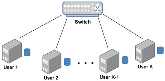
Figure 1.
The MapReduce system where multiple users connect with each other via a switch.
2.2. Mapreduce Process Description
The MapReduce-type task has Q output functions and N input files with F bits size . Similar to [24], we assume that the Q reduce functions are symmetrically assigned to K nodes and satisfy .
There are three phases in the whole process: map, data shuffling and reduce. In the mapping phase, according to the deposition set, each node stores and maps the local files to intermediate values and encodes them into packets; in the data shuffling phase, nodes broadcast the encoded packets to each other according to the broadcast set; in the reduce phase, each node decodes the received encoded packets and combines the local intermediate values to obtain the final desired information.
2.2.1. Map Phase
Given N input files , let denote the index set of files stored at node k, where , and be the map function which maps each file to Q intermediate values of size T, i.e.,
where g is of form . In the map phase, each node k maps each of its local file to Q intermediate values of size T as follows.
Similar to [24], we introduce the computation load r as average number of files placed and computed on each node, i.e., .
2.2.2. Shuffle Phase
In the shuffle phase, the nodes exchange data to obtain the desired intermediate values. Assume the shuffle phase takes place in I channel slots. At slot , the set of nodes that serve as transmitter nodes is denoted by and who serve as receivers is denoted by . Since we consider the half-duplex model where the node cannot transmit and receive signals at the same time, we have for all .
At time slot i, each node generates symbols and sends them to a set of nodes .
Definition 1
(Communication Load and Delay). Define the communication load L as the total number of bits communicated by the K nodes, normalized by , during the Shuffle phase. Define communication delay, D, as the time (in seconds) required in the shuffle phase such that all required contents are successfully sent.
2.2.3. Reduce Phase
Recall that represents the set of output functions to be reduced by node k, then the required intermediate value , where is generated locally and does not require other nodes to share. For a certain function , node k uses decoding function to decode desired intermediate values
For any , node k converts the decoded intermediate value into the desired result through the Reduce function .
Definition 2
(Execution Time). The achievable execution time of MapReduce task with parameters , denoted by , is defined as
where , D, represent the time cost in the initialization, map, shuffle and reduce steps, respectively.
According to Table 1 in [24] in actual TeraSort experiments, shuffle execution takes up most of the total time and leads to the communication bottleneck problem. Thus, in this paper, we mainly focus on reducing the overhead of shuffle, so the consideration of performance in the following paper is mainly its communication delay D.
2.3. Examples: The Uncoded Scheme and the CDC Scheme
For the uncoded scheme and the CDC scheme, since all nodes broadcast and send signals individually in sequence, and there is no situation in which signals are sent at the same time, their respective communication delays are
3. Main Results
Theorem 1.
In the case of allowing parallel communication, in the data interaction stage, the communication delay of the proposed scheme is
where Q length T intermediate values are computed from N input files, which correspond to Q output functions. For the general case of , the downward convex envelope composed of points can be reached.
Proof.
Please see the proposed scheme and analysis in Section 4. □
The first factor in is , which also appears in the formula, can be called the coding broadcast gain. This is because each encoded packet generated and broadcast by the node XORs is the information needed by r receiving nodes, so the total amount of transmitted data is reduced by r times.
The second factor of is , which can be called the parallel transmission gain. This is the core gain of this scheme, which is generated by sending information by two sending nodes in parallel in their respective broadcast groups without interfering with each other.
The third factor in is , appearing in both communication delay of the uncoded scheme and CDC scheme, which can be called the local computing gain. This is because each node has shares of N files in the file placement stage, so the intermediate value generated by this part can be directly obtained by local mapping without exchange with other nodes.
Compared with the CDC scheme, the algorithm of the proposed scheme only has one more subdivision for the encoding package, and the complexity of other parts is the same as that of the CDC scheme. The low degree of calculation does not greatly reduce the overall computational efficiency. Next, the communication delay of the uncoded scheme, the CDC scheme and the proposed scheme are compared through the numerical results. Figure 2 compares the communication delay of the uncoded, CDC and schemes as a function of the computational load r when both the given compute node K and the output function Q are 50. It can be clearly observed that when r is small, the proposed scheme can greatly reduce the communication delay, while when r is large, the communication delay of the proposed scheme is similar to that of the CDC scheme. The main reason is that the number of broadcast groups communicating in parallel in each time period equals . When r increases and decreases, when only one broadcast group is sending at a time, is equivalent to the scheme. When , , , compared to the CDC scheme, the scheme reduces the communication delay by 15 times, and the effect is very obvious. In [25], it is pointed out that with the increase in the computational load r, the complexity of the system increases, so it is recommended to use a smaller computational load in practical applications.
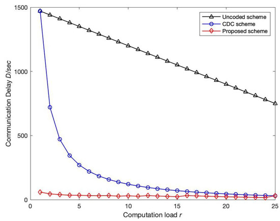
Figure 2.
Variation trend of communication delay D with computation load r: the computing node K and output function Q in a given network are 50. Number of file N and output function Q are both 50. In addition, the transmission rate C is 100 Mbps, while the length of intermediate value T is 100 Mbits. Compare the variation of communication delay with computing load for uncoded, CDC and proposed scheme.
Figure 3 compares the change trend of the communication delay of each scheme with the increase in the number of computing nodes in the network when the computing load is given. It can be seen that the proposed scheme is always better than the uncoded scheme and the CDC scheme. In addition, the communication delay of the uncoded scheme and the CDC scheme both increase with the increase in computing nodes. When , the proposed scheme cannot achieve parallel transmission of multiple broadcast groups, and there is no parallel transmission gain. The communication delay of the scheme is consistent with the CDC scheme, and the communication delay of the proposed scheme reaches the maximum when , and when multiple broadcast groups are allowed to transmit in parallel in the scheme, due to the increase of nodes, the overall communication delay of the broadcast of parallel transmission will decrease as the number of groups increases, which is very beneficial to a multi-node computing network. The communication delay as function of computation load r and the number of computing nodes are presented in Figure 4.
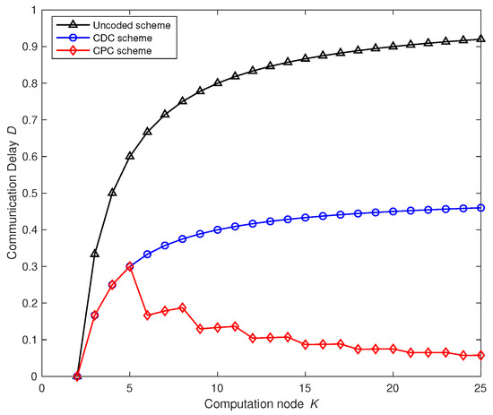
Figure 3.
Variation trend of communication delay D with the number of computing nodes K. The computation load r is 2, and the number of file N and output function are both 50. In addition, transmission rate C is 100 Mbps while the length of intermediate value T is 100 Mbits. The communication delay of uncoded computing, coded distributed computing and parallel coded computing changes with the number of computing nodes K in the network.
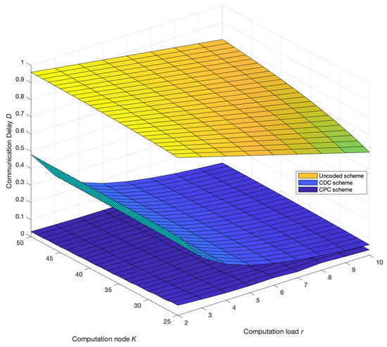
Figure 4.
Variation trend of communication delay D with the number of computing nodes K and computation load r. The number of file N and output function Q are both 50. In addition, transmission rate C is 100 Mbps while the length of the intermediate value T is 100 Mbits. The communication delay of the uncoded computing, coded distributed computing and parallel coded computing changes with the number of computing nodes K in the network.
4. The Proposed Coded Distributed Computing Scheme
Due to the advantages of centralized control, we can evenly distribute the workload of each node and the total length of the files placed. Assuming that each round of the system processes N files, Q reduce functions need to be calculated, and each node calculates different functions, then node k can be responsible for generating the operation result .
To better describe how nodes communicate in the data shuffling phase after file placement, define broadcast groups and broadcast sets as follows.
Definition 3
(Broadcast Group and Broadcast Set). A set is called a broadcast group if all nodes in can only exchange information with nodes within . Given an integer and multiple broadcast groups with , we define as the broadcast set.
Assume there exist different broadcast sets for K nodes, and each broadcast set contains broadcast groups , i.e.,
for , if , and
4.1. Map Phase
Let be the files stored by nodes in . Similarly, let be the intermediate values locally known by nodes in and related to the output functions in . Make each file equal in size and be placed r times repeatedly. In order to make the files symmetrically placed, is equal to the set of all the subsets of containing r elements, i.e, . Therefore, the number of files N is a multiple of , here for simplicity, set to . According to the definition of the computation load, we know that the computation load is r.
In the Map phase, each node k performs the Map operation to obtain the local intermediate values . The intermediate values that need to be exchanged during the data communication phase of the entire system are represented by .
4.2. Shuffle Phase
Recall that in the Map phase, each file is stored by r node nodes, and each file can be mapped to Q intermediate values. We first partition all nodes into groups and then present the data shuffle strategy.
Group Partitioning Strategy
The purpose of grouping is to make multiple broadcast groups transmit in parallel, and further reduce the communication delay. In addition, the synchronization problem must be solved in the process of parallel communication, so that broadcast groups in the same group can start and complete the communication tasks arranged in the group at the same time, and the broadcast set has completed the exchange of all coded packets in the group after communication.
Since the communication load of each broadcast group , denoted by , is the same, in order to achieve the goal of synchronously ending communication, the broadcast groups in each broadcast set must share the same communication load, and each broadcast group should repeat the same times among all broadcast sets . Let be the number of times that each broadcast group appears among .
Use index set to mark the groups where appears, . For the selection of , and , in order to reduce the additional error and communication delay in the process of splitting coded packets and synchronous communication, the values of and should be as small as possible.
Let the best cover and transfer complete.
Now we prove that there exists a group scheme , which satisfies the synchronization completion of communication and the group covers all broadcast groups in , then and .
Here, is the number of all permutations which choosing broadcast groups with size of ,
where is the number of all permutations and combinations of broadcast groups of size selected from all the remaining nodes when a broadcast set with a size of is fixed,
4.3. Data Shuffle Strategy
Given a broadcast set , and all broadcast groups parallel communicate information within their groups. In the following, we describe the data shuffle strategy in a broadcast group : , which appears times in
In a broadcast group , the intermediate values that need to be transmitted in the group are divided into equal-sized non-coincident parts:
where the superscript index i and k represent the index of broadcast set and the node k, who will later send these parts, respectively. Then, in partition , node , sends the following coded symbols to the nodes in :
After shuffling the packet communication among nodes in , each node receives coded symbols . Based on and its local intermediate values, node decodes the desired parts as follows:
Finally, the intermediate value segment corresponding to is coupled to obtain the intermediate value required by node k: .
The pseudocode for whole implementation algorithm of proposed scheme is given in Algorithm 1.
| Algorithm 1 Distributed computing process of parallel coding in lossless scenarios. |
| 1: , , if , and |
| 2: for do |
| 3: for do |
| 4: |
| 5: |
| 6: Split as |
| 7: for do |
| 8: Node k sends the to the nodes in with |
| 9: end for |
| 10: for do |
| 11: Node j decodes the desired parts as follows: |
| 12: end for |
| 13: end for |
| 14: end for |
| 15: for , do |
| 16: . |
| 17: end for |
4.4. Reduce Phase
After the decoding phase, node k obtains all and obtains the objective function calculation result through reduce function.
4.5. Analysis of Communication Delay
Since each node k broadcasts useful and decodable other r nodes in simultaneously, and no content is repeatedly sent, the multicast gain of the broadcast group is r. The communication load regarding the subset is as follows:
Since the communication content of each broadcast group is independent, the total communication load of the system is computed as follows.
In order to minimize the communication delay, the number of broadcast groups working in parallel should be the maximum, . By letting and using the strategies above, according to the Definition of communication delay in (1), it is obvious that the communication delay is
4.6. Illustrative Examples
Next, an example is used to illustrate the feasibility of the proposed scheme. Consider a MapReduce model with 6 computing nodes and 15 input files, where each file is stored by 2 nodes, needs to process 6 output functions, and distribute tasks symmetrically so that each node processes 1 output function.
Then in the data shuffling process of the proposed scheme, there is a certain moment, as shown in Figure 5, and there are two broadcast groups in the system (that is, the broadcast group 1 composed of nodes 1, 2, and 3, nodes 4, 5, and 6). The constituted broadcast group 2 transmits and exchanges information that is independently and unrelated to each other. As can be seen from the figure, node 1 stores files 1, 2, 3, 4 and 5, and the output function to be processed is an orange circle. Node 2 stores files 1, 6, 7, 8 and 9, and the output function to be processed is the blue square. Node 3 stores files 2, 6, 10, 11 and 12, and the output function that needs to be processed is the yellow corner. In the broadcast group formed by nodes 1, 2, and 3; nodes 2 and 3 both generate the intermediate value orange 6 through the local map operation, nodes 1 and 2 both generate the intermediate value yellow 1 locally, and similarly, nodes 1 and 3 both generate the intermediate value orange 6. The median value is blue 2.
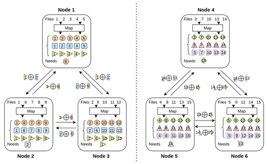
Figure 5.
Example of coding strategy for simultaneous transmission of two broadcast groups: a distributed computing network composed of nodes, including input files, and each file is stored by nodes. A total of output functions need to be processed.
Then node 1 can send yellow 1 XOR blue 2 to nodes 2 and 3, similarly node 2 sends yellow 1 XOR orange 6 to nodes 1 and 3, and node 3 sends blue 2 XOR orange 6 to nodes 1 and 2. Since each intermediate value is sent twice, in order to avoid the repeated transmission of the message, the intermediate value to be sent is divided into two disjoint intermediate value segments, and then the encoded packet is sent to the nodes in the group by XOR.
After node 1 receives the XOR encoded packets sent by the other two nodes (right yellow 1 XOR left orange 6, left blue 2 XOR right orange 6), it separates the encoding package with the local intermediate value segment (right orange 6). (Yellow 1, left blue 2) XOR, so you can obtain the middle value segment (left orange 6, right orange 6), and then combine the middle value segments to obtain the required middle value (orange 6). The same is true for the other two nodes. At the same time when this broadcast group is sent, the broadcast groups composed of three nodes, 4, 5, and 6, communicate at the same time, and adopt the same sending strategy to exchange messages within the group. So at the same time, as shown in Figure 6, two nodes are sending information to respective broadcast groups.
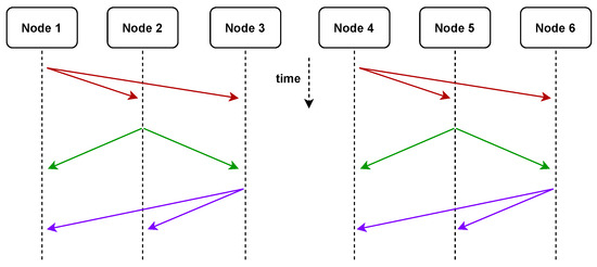
Figure 6.
An example of coding strategy for the simultaneous transmission of two broadcast groups. At the same time, both nodes can send messages without interference. Solid lines from the same point represent multicast messages.
Due to the small number of computing nodes in this example, when three nodes form a broadcast group, there is no grouping strategy that makes the same broadcast group appear multiple times. As in the above example, the broadcast group formed by nodes only appears once, so the encoded packets that need to be sent do not need to be further divided. However, when nodes are added to form a more complex network, further processing of the encoded packets is required. For example, when the network contains 9 computing nodes, 36 input files, and the computing load is 2, the broadcast group composed of nodes 1, 2, and 3 will appear in multiple broadcast groups. If there is , and other grouping situations, in all groups, the number of times the communication group appears is , then in order to avoid redundant sending, it is necessary to divide the encoded packets sent in the broadcast group into 10 sub-encoded packets evenly and disjointly in the presence of different groups of sent in.
5. Conclusions
This paper proposed a coded parallel transmission scheme for the half-duplex MapReduce-type distributed computing systems. Our scheme allows the network to have multiple computing nodes broadcast the encoded intermediate value fragments to other computing nodes at the same time during the data shuffling phase. We delicately design the data placement, message symbols encoding, data shuffling and decoding such that as many computing nodes as possible participate in the transmission or receiving, as large of a multicast gain as possible is achieved in each transmission, and no content is repetitively transferred. It can be proved that our scheme can significantly reduce the communication delay compared to the CDC scheme. Our scheme can make better use of the computing resources, as its communication delay decreases with the number of computing nodes, while the communication delay of CDC is a monotonically increasing function of the number of computing nodes.
Author Contributions
Supervision, Y.W.; Writing—original draft, Q.Z.; Writing—review & editing, K.Y. All authors have read and agreed to the published version of the manuscript.
Funding
This work was supported in part by the National Nature Science Foundation of China (NSFC) under Grant 61901267.
Data Availability Statement
All data were presented in main text.
Conflicts of Interest
The authors declare no conflict of interest.
References
- Cristea, V.; Dobre, C.; Stratan, C.; Pop, F.; Costan, A. Large-Scale Distributed Computing and Applications: Models and Trends Information Science Reference; IGI Publishing: Hershey, PA, USA, 2010. [Google Scholar]
- Nikoletseas, S.; Rolim, J.D. Theoretical Aspects of Distributed Computing in Sensor Networks; Springer: Berlin/Heidelberg, Germany, 2011. [Google Scholar]
- Corbett, J.C.; Dean, J.; Epstein, M.; Fikes, A.; Frost, C.; Furman, J.J.; Ghemawat, S.; Gubarev, A.; Heiser, C.; Hochschild, P.; et al. Spanner: Google’s globally distributed database. ACM Trans. Comput. Syst. 2013, 31, 1–22. [Google Scholar] [CrossRef]
- Valentini, G.L.; Lassonde, W.; Khan, S.U.; Min-Allah, N.; Madani, S.A.; Li, J.; Zhang, L.; Wang, L.; Ghani, N.; Kolodziej, J.; et al. An overview of energy efficiency techniques in cluster computing systems. Clust. Comput. 2013, 16, 3–15. [Google Scholar] [CrossRef]
- Sadashiv, N.; Kumar, S.D. Cluster, grid and cloud computing: A detailed comparison. In Proceedings of the 2011 6th International Conference on Computer Science Education (ICCSE), Singapore, 3–5 August 2011; pp. 477–482. [Google Scholar]
- Hussain, H.; Malik, S.U.R.; Hameed, A.; Khan, S.U.; Bickler, G.; Min-Allah, N.; Qureshi, M.B.; Zhang, L.; Yongji, W.; Ghani, N.; et al. A survey on resource allocation in high performance distributed computing systems. Parallel Comput. 2013, 39, 709–736. [Google Scholar] [CrossRef]
- Idrissi, H.K.; Kartit, A.; El Marraki, M. A taxonomy and survey of cloud computing. In Proceedings of the 2013 National Security Days (JNS3), Rabat, Morocco, 26–27 April 2013; pp. 1–5. [Google Scholar]
- Dean, J.; Ghemawat, S. Mapreduce: Simplified data processing on large clusters. Commun. ACM 2008, 51, 107–113. [Google Scholar] [CrossRef]
- Jiang, D.; Ooi, B.C.; Shi, L.; Wu, S. The performance of mapreduce: An in-depth study. Proc. VLDB Endow. 2010, 3, 472–483. [Google Scholar] [CrossRef]
- Ahmad, F.; Chakradhar, S.T.; Raghunathan, A.; Vijaykumar, T.N. Tarazu: Optimizing mapreduce on heterogeneous clusters. ACM SIGARCH Comput. Archit. News 2012, 40, 61–74. [Google Scholar] [CrossRef]
- Guo, Y.; Rao, J.; Cheng, D.; Zhou, X. ishuffle: Improving hadoop performance with shuffle-on-write. IEEE Trans. Parallel Distrib. Syst. 2016, 28, 1649–1662. [Google Scholar] [CrossRef]
- Chowdhury, M.; Zaharia, M.; Ma, J.; Jordan, M.I.; Stoica, I. Managing data transfers in computer clusters with orchestra. ACM SIGCOMM Comput. Commun. Rev. 2011, 41, 98–109. [Google Scholar] [CrossRef]
- Zhang, Z.; Cherkasova, L.; Loo, B.T. Performance modeling of mapreduce jobs in heterogeneous cloud environments. In Proceedings of the 2013 IEEE Sixth International Conference on Cloud Computing, Washington, DC, USA, 9–12 December 2013; pp. 839–846. [Google Scholar]
- Georgiou, Z.; Symeonides, M.; Trihinas, D.; Pallis, G.; Dikaiakos, M.D. Streamsight: A query-driven framework for streaming analytics in edge computing. In Proceedings of the 2018 IEEE/ACM 11th International Conference on Utility and Cloud Computing (UCC), Zurich, Switzerland, 17–20 December 2018. [Google Scholar]
- Krizhevsky, A.; Sutskever, I.; Hinton, G.E. Imagenet classification with deep convolutional neural networks. Adv. Neural Inf. Process. Syst. 2012, 25. [Google Scholar] [CrossRef]
- Attia, M.A.; Tandon, R. Combating computational heterogeneity in large-scale distributed computing via work exchange. arXiv 2017, arXiv:1711.08452. [Google Scholar]
- Wang, D.; Joshi, G.; Wornell, G. Using straggler replication to reduce latency in large-scale parallel computing. ACM Sigmetrics Perform. Eval. Rev. 2015, 43, 7–11. [Google Scholar] [CrossRef]
- Ahmad, F.; Lee, S.; Thottethodi, M.; Vijaykumar, T.N. Mapreduce with communication overlap (marco). J. Parallel Distrib. Comput. 2013, 73, 608–620. [Google Scholar] [CrossRef]
- Nicolae, B.; Costa, C.H.; Misale, C.; Katrinis, K.; Park, Y. Leveraging adaptive i/o to optimize collective data shuffling patterns for big data analytics. IEEE Trans. Parallel Distrib. Syst. 2016, 28, 1663–1674. [Google Scholar] [CrossRef][Green Version]
- Yu, W.; Wang, Y.; Que, X.; Xu, C. Virtual shuffling for efficient data movement in mapreduce. IEEE Trans. Comput. 2013, 64, 556–568. [Google Scholar] [CrossRef]
- Zaharia, M.; Borthakur, D.; Sen Sarma, J.; Elmeleegy, K.; Shenker, S.; Stoica, I. Delay scheduling: A simple technique for achieving locality and fairness in cluster scheduling. In Proceedings of the 5th European Conference on Computer Systems, Paris, France, 13–16 April 2010; pp. 265–278. [Google Scholar]
- Maddah-Ali, M.A.; Niesen, U. Fundamental limits of caching. IEEE Trans. Inf. Theory 2014, 60, 2856–2867. [Google Scholar] [CrossRef]
- Maddah-Ali, M.A.; Niesen, U. Decentralized coded caching attains order-optimal memory-rate tradeoff. IEEE/ACM Trans. Netw. 2015, 23, 1029–1040. [Google Scholar] [CrossRef]
- Li, S.; Maddah-Ali, M.A.; Yu, Q.; Avestimehr, A.S. A fundamental tradeoff between computation and communication in distributed computing. IEEE Trans. Inf. Theory 2018, 64, 109–128. [Google Scholar] [CrossRef]
- Shariatpanahi, S.P.; Motahari, S.A.; Khalaj, B.H. Multi-server coded caching. IEEE Trans. Inf. Theory 2016, 62, 7253–7271. [Google Scholar] [CrossRef]


Publisher’s Note: MDPI stays neutral with regard to jurisdictional claims in published maps and institutional affiliations. |
© 2022 by the authors. Licensee MDPI, Basel, Switzerland. This article is an open access article distributed under the terms and conditions of the Creative Commons Attribution (CC BY) license (https://creativecommons.org/licenses/by/4.0/).