Article

Coded Caching for Combination Networks with Multiaccess

1
Guangxi Key Lab of Multi-Source Information Mining and Security, Guangxi Normal University, Guilin 541004, China
2
School of Mathematics and Statistics, Guangxi Normal University, Guilin 541004, China
*
Author to whom correspondence should be addressed.
Information 2022, 13(4), 191; https://doi.org/10.3390/info13040191
Submission received: 13 March 2022 / Revised: 5 April 2022 / Accepted: 6 April 2022 / Published: 11 April 2022
(This article belongs to the Special Issue Advanced Technologies in Storage, Computing, and Communication)

Abstract

:
In a traditional ( H , r ) combination network, each user connects to a unique set of r relays. However, few research efforts have considered the ( H , r , u ) multiaccess combination network problem wherein each unique set of r relays is connected by u users. In this paper, we focus on designing coded caching schemes for a ( H , r , u ) multiaccess combination network. By directly applying the well-known coding method (proposed by Zewail and Yener) for a ( H , r ) combination network, a coded caching scheme (called ZY scheme) for ( H , r , u ) multiaccess combination network is obtained. However, its subpacketization has an exponential order with the number of users which leads to high implementation complexity. In order to reduce subpacketization, a direct construction of a coded caching scheme (called the direct scheme) for ( H , r , u ) multiaccess combination network is proposed by means of combinational design theory, where the parameter u must be a combinatorial number. For the arbitrary parameter u, the hybrid construction of a coded caching scheme (called the hybrid scheme) for the ( H , r , u ) multiaccess combination network is proposed based on the direct scheme. Theoretical and numerical analysis shows that the direct scheme and the hybrid scheme have a smaller transmission load for each relay compared with the naive scheme (which is obtained by repeatedly applying the coded caching scheme for a traditional ( H , r ) combination network by u times) and have much lower subpacketization compared with the ZY scheme.

1. Introduction

Coded caching, proposed by Maddah-Ali and Niesen (MN) in [1], not only utilizes users’ cache memories to shift some of the network traffic to off-peak hours but also to create multicast opportunities that further reduce network congestion during peak traffic hours. The first coded caching system studied was the following shared-link broadcast network with end-user-caches: there exists a single server with N files with the same length connecting to K users through a shared error-free broadcast link, wherein each user has a cache of size M files. An F-division ( K , M , N ) -coded caching scheme consists of two phases: the placement phase during the off-peak traffic times and delivery phase during peak traffic times. In the placement phase, the server divides each file into F packets (F is referred to as subpacketization) with the same length, and then places some packets of size M files in each user’s cache without knowledge of later users’ demands. If the server directly places some packets in each user’s cache, without coding, the placement is said to be uncoded. Otherwise, the placement is called coded. In the delivery phase, each user’s demand arrives at the server. According to the users’ demands, the server transmits coded packets (XOR of the required packets) in order to satisfy all users’ demands with the help of their caches. The maximum normalized transmission amount over all possible demands is defined as the transmission load R, and the coded caching gain is defined as K ( 1 M N ) R , where K ( 1 M N ) is the transmission load of the conventional uncoded caching scheme. The goal is to design a coded caching scheme with transmission load R and the subpacketization F as small as possible due to the efficiency requirements of transmission and low implementation complexity. The above coded caching model is called a ( K , M , N ) caching or MN caching system, for which Maddah-Ali and Niesen [1] proposed the first coded caching scheme (called the MN scheme) which is optimal under the constraint of uncoded placement and K N [2]. Yan et al. [3] proposed a combinatorial structure called placement delivery array (PDA) to design a coded caching scheme for the MN caching system. It is worth noting that the MN scheme can be represented by a special PDA which is called the MN PDA.

1.1. Traditional Combination Network Caching System

Compared with the MN caching system, a more practical system wherein users may communicate with the server through intermediate relays has gained attention. Since the analysis of relay networks with arbitrary topologies is challenging, many studies have focused on a symmetric version of this general problem known as combination networks with end-user-caches. The ( H , r , M , N ) combination network caching system was first proposed in [4] as follows: a server with N files connects H relays (without caches), which in turns connect K = H r users, where each user is equipped with a cache of size M files and each user is connected to a unique set of r relays. All links are assumed to be error-free and interference-free. The transmission load for each relay is defined as the maximum normalized transmission amount from the server to each relay over all relays and all possible demands. The objective is to design a coded caching scheme with the transmission load for each relay and the subpacketization as small as possible.
The first two schemes for combination networks were proposed in [4]: one based on uncoded placement and routing in the delivery phase, and the other based on the placement strategy of the MN scheme and a linear code for delivery. The authors in [5] proposed a scheme based on coded placement that effectively splits the combination network into H parallel MN caching systems, each of which serves H 1 r 1 users using the MN scheme. This scheme works for any parameters H, r and memory ratio M N and the achieved transmission load for each relay is approximately 1 r of the transmission load of MN scheme. Furthermore, it can be used to deal with any relay networks with arbitrary topologies. There are some other studies on improving the transmission load for each relay based on MN scheme; for instance, [6,7,8,9,10,11] etc. Since the subpacketization of the MN scheme exponentially increases with the number of users, all of the above known schemes have high subpacketization, which implies that these schemes not only have high implementation complexity but also cannot be used when the files in the server are not large enough.
In order to design a scheme with low subpacketization for the combination network caching system, the authors in [12] proposed the concept of combinatorial placement delivery array (CPDA) based on PDA which has been widely studied in [13,14]. When r divides H (denoted by r | H ), based on the MN scheme, they proposed a scheme with lower subpacketization while the achieved transmission load for each relay is equal to that of the scheme in [5]. However, its subpacketization still increases exponentially with the number of users. The authors in [15] showed that the strongly coloring PDA in [16] is a CPDA, which is constructed by the strong coloring in the bipartite graph [17]. Consequently, two classes of CPDAs were obtained in [15], which lead to schemes with lower subpacketization and without the limitation of r | H compared with the scheme in [12].

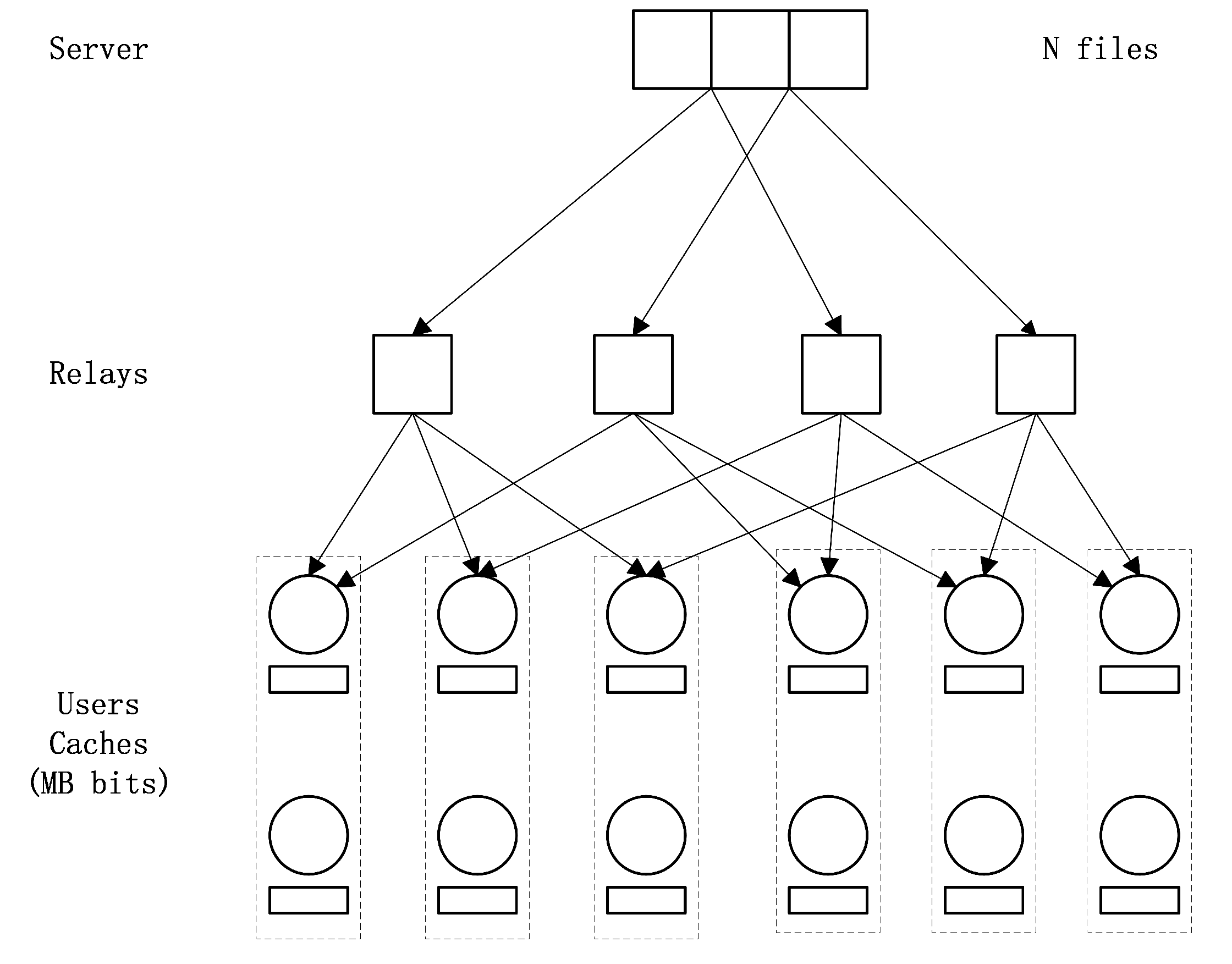
1.2. Multiaccess Combination Network Caching System

It should be noted that all of the above studies are under the assumption that each user is connected to a distinct set consisting of r relays. However, the number of users in a network system may be time-varying [18] in practice. So it always happens that multiple users are connected to the same r relays when the number of users is larger than H r . Therefore, it is meaningful to study a combination network caching system where multiple users are connected to the same r relays. Assuming that there are exactly u users connected to a unique set of r relays. Such a setting is denoted by an ( H , r , u , M , N ) multiaccess combination network caching system.
Clearly, an ( H , r , 1 , M , N ) multiaccess combination network caching system is an ( H , r , M , N ) combination network caching system, as proposed in [4]. We can therefore generate an ( H , r , u , M , N ) multiaccess combination network caching scheme by the repeated application of an ( H , r , M , N ) combination network caching scheme u times. However, in this naive strategy, not only will the coded caching gain among the users who are connected to the same r relays be omitted, but the coded caching gain among the users who are connected to different relay subsets containing at least one common relay will not be fully considered. In order to make the transmission load for each relay as small as possible, we prefer to design a scheme with the coded caching gain as large as possible. This motivates us to study the multiaccess combination network caching problem, wherein the basic idea is to generate coded caching gain among all the users as large as possible instead of generating coded caching gain only among H r users who are connected to distinct sets of r relays. Specifically, the following main results are obtained in this paper.
  • By using the idea proposed in [5], a scheme (called the ZY scheme) for the multiaccess combination network is obtained, which works for any parameters H, r, u and any memory ratio M N , and the achieved transmission load for each relay is approximately 1 r of the transmission load of MN scheme since the coded caching gain among the users who are connected to the same relay is fully considered. However, its subpacketization exponentially increases with the number of users.
  • In order to reduce subpacketization, we omit the coded caching gain among the users who are connected to the same r relays and consider the coded caching gain among the users who are connected to different relay subsets containing at least one common relay as much as possible, and directly construct a CPDA P from the view point of combinatorial design theory, which leads to a new scheme (called the direct scheme) for the multiaccess combination network with lower subpacketization. Since some special combinatorial structure is used in this scheme, the parameter u has to be a combinatorial number.
  • For arbitrary parameter u, based on the proposed direct scheme and the MN PDA, a hybrid construction of CPDA is proposed which leads to a new scheme (called the hybrid scheme) for the multiaccess combination network. It is worth noting that the hybrid scheme not only has the same coded caching gain among the users who are connected to different relay subsets containing at least one common relay as the direct scheme, but also fully considers the coded caching gain among the users who are connected to the same r relays by increasing some subpacketization.
The rest of this paper is organized as follows. In Section 2, the traditional combination network caching system is extended to the multiaccess combination network caching system, and the concepts of PDA and CPDA are briefly reviewed. In Section 3, three schemes for the multiaccess combination network are proposed. In Section 4, performance analysis is provided. Finally, a conclusion is given in Section 5 while some proofs are provided in the Appendix A and Appendix B.

2. Preliminaries

In this section, the multiaccess combination network caching system and the concepts of PDA and CPDA are introduced. First, the following notations are useful in this paper.
  • [ a : b ] : = { a , a + 1 , , b } , [ a ] : = { 1 , 2 , , a } .
  • m o d ( a , q ) denotes the least non-negative residue of a modulo q. < a > q : = m o d ( a , q ) if m o d ( a , q ) 0 , otherwise < a > q : = q .
  • For any set H and for any positive integer r with r < | H | , H r : = { A | A H , | A | = r } , i.e., H r is the collection of r-sized subsets of H , where | · | denotes the cardinality of a set.
  • Given an array P = ( p j , k ) j [ F ] , k [ K ] with alphabet [ S ] { } , we define P + a = ( p j , k + a ) j [ F ] , k [ K ] and P × a = ( p j , k × a ) j [ F ] , k [ K ] for any integer a, where a + = , a × = .
  • For any two vectors x and y with the same length, d ( x , y ) is the number of coordinates in which x and y differ, w t ( x ) is the weight of x , i.e., the number of nonzero coordinates of x . For example, if x = ( 0 , 1 , 2 , 1 ) and y = ( 0 , 1 , 3 , 4 ) , then d ( x , y ) = 2 and w t ( x ) = 3 .
  • For any vector f with length H and for any nonempty subset T [ H ] , f | T is a vector with length | T | obtained by taking only the coordinates with subscript j T . For example, if f = ( 0 , 2 , 3 , 1 ) and T = { 1 , 3 } , then f | T = ( 0 , 3 ) .

2.1. Placement Delivery Array

Yan et al. [3] proposed a combinatorial structure, called placement delivery array (PDA) to characterize the placement phase and delivery phase of a scheme for the MN caching system simultaneously.
Definition 1.
(PDA, [3]) For positive integers K, F, Z and S, an F × K array P = ( p j , k ) , j [ F ] , k [ K ] , composed of a specific symbol “∗” called star and S integers in [ S ] , is called a ( K , F , Z , S ) placement delivery array (PDA) if it satisfies the following conditions:
C1.
Each column has exactly Z stars.
C2.
Each integer in [ S ] occurs at least once.
C3.
For any two distinct entries p j 1 , k 1 and p j 2 , k 2 , p j 1 , k 1 = p j 2 , k 2 = s is an integer only if
  • a.  j 1 j 2 , k 1 k 2 , i.e., they lie in distinct rows and distinct columns; and
  • b.  p j 1 , k 2 = p j 2 , k 1 = , i.e., the corresponding 2 × 2 subarray formed by rows j 1 , j 2 and columns k 1 , k 2 must be of the following form
    s s o r s s .
Example 1.
It is easy to verify that the following array is a ( 6 , 4 , 2 , 4 ) PDA,
P = 1 2 3 1 2 4 1 3 4 2 3 4 .
The first PDA was proposed by Maddah-Ali and Niesen in [1,3].
Lemma 1.
(MN PDA, MN scheme [1,3]) For any positive integers K, M and N with M < N , if K M / N is an integer, there exists a ( K , K K M / N , K 1 K M / N 1 , K K M / N + 1 ) PDA, which leads to a ( K , M , N ) coded caching scheme (MN scheme) with subpacketization F = K K M / N and transmission load R = K ( 1 M / N ) K M / N + 1 for the MN caching system.

2.2. Multiaccess Combination Network Caching System

We consider an ( H , r , u , M , N ) multiaccess combination network caching system (see Figure 1) in which a server S e r containing N files W = { W 1 , W 2 , , W N } , each of which is uniformly distributed in { 0 , 1 } B for some positive integer B, connects H relays through H error-free and interference-free links. Each set of r relays connects u users, so that the total number of users is K = u H r . Each user has a storage capacity of size M files where 0 < M < N and all relays have no cache memory. Each relay h could broadcast the intermediate signals from the server to the users who are connected to it. The users are denoted by K = { k = ( A , i ) | A [ H ] r , i [ u ] } and user ( A , i ) is connected to relay h if and only if h A . The set of relays which connect user k K is denoted by A k .
An F-division ( H , r , u , M , N ) multiaccess combination network caching scheme contains the two following phases.
  • Placement phase: Each file is divided into F packets of equal size. Then, each user k K directly accesses the file library W and stores some packets or linear combinations of some packets of the N files in its cache. The set of cached packets by user k is denoted by Z k whose size is at most M files. That is, for each user k K , there exists a function ϕ k : { 0 , 1 } N B { 0 , 1 } M B to generate the cache contents Z k = ϕ k ( ( W n ) n [ N ] ) . Let Z = { Z k | k K } .
  • Delivery phase: Assume that each user k = ( A , i ) K randomly requests one file from the file library W . The demand vector is represented by d = ( d k ) k K , which implies that the user k requests the d k th file W d k where d k [ N ] . Given ( Z , d ) , the server sends a message X S e r h of size L S e r h bits to relay h [ H ] . Then, relay h [ H ] forwards X S e r h to its connecting users. User k can recover its desired file W d k by { X S e r h | h A } with the help of Z k . This phase can be represented by the following encoding functions and decoding functions.
    -
    The H encoding functions: For each relay h [ H ] ,
    ψ S e r h : { 0 , 1 } N B × { 0 , 1 } K M B × [ N ] K { 0 , 1 } L S e r h
    generates the transmitted message X S e r h ψ S e r h ( W , Z , d ) from the server to the relay h. It is a function of the library W , the cached contents of all users Z and the demand vector d .
    -
    The K decoding functions: For each user k = ( A , i ) K ,
    μ k : { 0 , 1 } h A L S e r h × { 0 , 1 } M B × [ N ] K { 0 , 1 } B
    decodes the requested file of user k from all messages received by user k and its own cache, i.e.,
    W d k = μ k X S e r h | h A , Z k , d .
The transmission load for each relay is defined as
R = max d [ N ] K , h [ H ] L S e r h B .

2.3. Combinatorial Placement Delivery Array

Definition 2.
(CPDA, [12]) For any positive integers H, r and u with r < H , a ( K = u H r , F , Z , S ) PDA P is called a ( K , F , Z , S ) combinatorial placement delivery array (CPDA) if it satisfies the following condition.
C4.
All the columns can be labeled by K = { ( A , i ) | A [ H ] r , i [ u ] } such that for any s [ S ] , the intersection of the first coordinate A of all column labels ( A , i ) satisfying that s appears in column ( A , i ) , denoted by I s , is not empty.
The definition of CPDA is proposed based on the definition of PDA. Thus, a CPDA must be a PDA. However, the converse does not necessarily hold since CPDA has another requirement, i.e., the condition C4. The detailed discussion of the relationship between PDA and CPDA could be found in [15]. Based on a CPDA, a scheme for the multiaccess combination network can be obtained by using Algorithm 1.
Algorithm 1 Caching scheme based on ( K , F 1 , Z , S ) CPDA in [15]
      procedure Placement( P , W )
  2:     Split each file W n W into F 1 packets, i.e., W n = { W n , j | j [ F 1 ] } .
          for  k K  do
  4:           Z k { W n , j | p j , k = , j [ F 1 ] , n [ N ] }
          end for
  6: end procedure
      procedure Delivery( P , W , d )
  8:     for  s [ S ]  do
                X s = p j , k = s , j [ F 1 ] , k K W d k , j ;
10:           I s = p j , k = s , j [ F 1 ] , k K A k = { h s , 1 , h s , 2 , , h s , μ s } , 1 μ s r ;
               Divide X s into μ s sub-packets, i.e., X s = { X s , 1 , X s , 2 , , X s , μ s } ;
12:          for  l [ μ s ]  do
                    Server sends X s , l to relay h s , l ;
14:               Relay h s , l broadcasts X s , l to its connecting users;
               end for
16:     end for
      end procedure
From Algorithm 1, a ( K , F 1 , Z , S ) CPDA P can be intuitively explained as follows.
  • Each row j [ F 1 ] represents the index of the jth packet of all files and each column k K represents user k . If p j , k = , then user k has cached the jth packet of all files. The condition C1 of Definition 1 therefore implies that each user caches M = Z F 1 N files.
  • If p j , k = s is an integer, it means that the jth packet of all files is not stored by user k . Then, the XOR of the requested packets indicated by s is generated by the server at time slot s, denoted by X s . If the set I s defined in the condition C4 of Definition 2 is { h s , 1 , h s , 2 , , h s , μ s } where 1 μ s r , then X s is divided into μ s sub-packets, i.e., X s = { X s , 1 , X s , 2 , , X s , μ s } . Finally, for any l [ μ s ] , the server sends X s , l to relay h s , l and relay h s , l forwards X s , l to its connecting users. The subpacketization is therefore at most r F 1 . The condition C4 of Definition 2 guarantees that user k can receive the whole message X s since user k is connected to each relay in I s . The condition C3 of Definition 1 guarantees that user k can recover its requested packet indicated by s from X s since it has cached all the other packets in message X s except its requested one. The occurrence number of integer s in P denoted by g s is the coded caching gain at time slot s since message X s is useful for g s users.
  • The condition C2 of Definition 1 implies that the number of messages X s sent by the server is exactly S. If the size of I s is a constant for each s [ S ] , assume that | I s | = μ , and if the number of I s containing h is a constant for each relay h [ H ] , assume that | { I s | h I s , s [ S ] } | = ν ; then, we have ν H = μ S . The transmission load for each relay is therefore R = ν 1 μ F 1 = S H F 1 .
Lemma 2.
([15]) Given a ( K = u H r , F 1 , Z , S ) CPDA for any positive integers H, r and u with r < H , we have an ( H , r , u , M , N ) multiaccess combination network caching scheme with memory ratio M N = Z F 1 and subpacketization F r F 1 . Moreover, if the size of I s , which is defined in Definition 2, is a constant for each s [ S ] and if the number of I s containing h is a constant for each relay h [ H ] , the transmission load for each relay is R = S H F 1 .
In a PDA, a star not contained in any subarray shown as (1) in C3-b of Definition 1 is called useless. The authors in [19] pointed out that useless stars not only make no contribution to reducing the transmission load but also result in high subpacketization. If each column of a ( K , F , Z , S ) PDA has Z useless stars, the authors in [19] improved the scheme in [16] by deleting all the useless stars and using an [ F , F Z ] q maximum distance separable (MDS) code [20] for some prime power q, and came up with a new coded caching scheme with a smaller transmission load and subpacketization than the original scheme in [16] for the same number of users and memory ratio. In fact, this idea also works for the multiaccess combination network caching system.
Lemma 3.
Given a ( K = u H r , F 1 , Z , S ) CPDA P for any positive integers H, r and u with r < H , assume that there exist Z useless stars in each column of P . Then, we have an ( H , r , u , M , N ) multiaccess combination network caching scheme with memory ratio M N = Z Z F 1 Z and subpacketization F r ( F 1 Z ) . If the size of I s , which is defined in Definition 2, is a constant for each integer s [ S ] and if the number of I s containing h is a constant for each relay h [ H ] , the transmission load for each relay is R = S H F 1 Z .
Proof. 
Assume that P is a ( K = u H r , F 1 , Z , S ) CPDA wherein each column has Z useless stars, delete the Z useless stars in each column and we obtain a new array P = ( p j , k | j [ F 1 ] , k K ) . Clearly each column of P has Z blanks, Z Z stars and F 1 Z integers. Based on P , we modify the placement strategy in Algorithm 1 as follows: the server divides each file into F 1 Z equal-sized packets and then encodes them using an [ F 1 , F 1 Z ] q MDS code for some prime power q. The resulting encoded packets are denoted by W n , 1 , W n , 2 , , W n , F 1 for each file W n where n [ N ] . Using the caching strategy in Lines 3–5 in Algorithm 1, each user k caches Z k = { W n , j | p j , k = , j [ F 1 ] , n [ N ] } . Clearly, the memory ratio of each user is M N = Z Z F 1 Z . Now, let us consider its subpacketization and transmission load for each relay. For any request vector d in the delivery phase, we use the same delivery strategy as in Algorithm 1. Then, each user can obtain exactly F 1 Z required coded packets. From the property of an [ F 1 , F 1 Z ] q MDS code, each user can recover its requested file. Since the size of I s is a constant for each integer s [ S ] and the number of I s containing h is a constant for each relay h [ H ] , the transmission load for each relay is R = S H F 1 Z . □
Remark 1.
Given a ( K , F 1 , Z , S ) CPDA P , if each column of P has Z useless stars, then the scheme in Lemma 3 has a smaller memory ratio and subpacketization than the scheme in Lemma 2 since Z F 1 > Z Z F 1 Z and F 1 > F 1 Z always hold for any positive integer Z < Z . It is worth noting that for the scheme in Lemma 3, the operation field must be O ( r F 1 ) ; hence, the size of each packet must be approximately log 2 ( r F 1 ) bits in length. This implies that the size of each file in the server must be more than log 2 ( r F 1 ) ( r ( F 1 Z ) ) bits.

3. The Schemes for the Multiaccess Combination Network

In this section, we will propose three coded caching schemes for the multiaccess combination network caching system. The first one is directly obtained from the idea in [5]. The second one is from a direct construction of CPDA via combinatorial design theory and the third one is from a hybrid construction of CPDA based on the CPDA directly constructed before and the MN PDA.

3.1. ZY Scheme

Since the scheme in [5] can be used to deal with any relay networks with arbitrary topologies, it also works for the multiaccess combination network caching setting. Specifically, from the idea in [5], we can obtain an ( H , r , u , M , N ) multiaccess combination network caching scheme as follows. Firstly, the server divides each file into r packets and then encodes them into H coded packets by an [ H , r ] q MDS code for some prime power q. Denote the hth coded packet of all files by W ( h ) = { W n ( h ) | n [ N ] } . It is worth noting that the size of each coded packet is B r bits. Secondly, for each relay h, by taking the hth coded packet of all files W ( h ) as the file library and using the ( K ˜ = u H 1 r 1 , M , N ) MN scheme, the server sends all required coded signals to relay h, and relay h forwards them to its connecting users. Let t = K ˜ M N , and then each user caches exactly r K ˜ 1 t 1 r K ˜ t N B = M B bits since each user is just connected to r relays. Thus, the transmission load for each relay is R = K ˜ ( 1 M / N ) r ( K ˜ M / N + 1 ) . That is the following result.
Lemma 4.
(ZY scheme) For any positive integers H, r, u, M and N with r < H and M < N , let K ˜ = u H 1 r 1 , if t = K ˜ M N is an integer, we have an ( H , r , u , M , N ) multiaccess combination network caching scheme with subpacketization F = r K ˜ t and transmission load for each relay R = K ˜ ( 1 M N ) r ( t + 1 ) .
It is easy to verify that the transmission load for each relay of the ZY scheme is approximately 1 r of the transmission load of the MN scheme. However, the subpacketization of the ZY scheme is exponential in order with K ˜ = u H 1 r 1 , which may lead to high implementation complexity and infeasibility in reality. Therefore, reducing the subpacketization while slightly increasing the transmission load for each relay as the tradeoff is very meaningful.

3.2. The Direct Scheme

In this section, we propose a direct construction of CPDA by means of combinatorial design theory, which leads to a multiaccess combination network caching scheme with much lower subpacketization than the ZY scheme in Lemma 4.
Construction 1.
For any positive integers H, r, a, ω and λ with max { ω , λ } r < H and a < H , let the row index set F and the column index set K be
F = f = ( f 1 , f 2 , , f H ) { 0 , 1 } H | w t ( f ) = a , K = k = ( T , b ) T [ H ] r , b { 0 , 1 } r , w t ( b ) = r ω ,
respectively. An H a × r ω H r array P = ( p f , k ) f F , k K with T = { δ 1 , δ 2 , , δ r } [ H ] , δ 1 < δ 2 < < δ r and b = ( b 1 , b 2 , , b r ) is defined as
p f , k = ( e , C ) i f d ( f | T , b ) = r λ , Otherwise ,
where e = ( e 1 , e 2 , , e H ) { 0 , 1 } H is defined as
e i = b v i f i = δ v , v [ r ] , f i Otherwise
and
C = { δ v | f δ v = b v , v [ r ] } { δ 1 , δ 2 , , δ r } .
Clearly, we have | C | = λ from (3).
Example 2.
When H = 4 , a = 2 , r = 2 , ω = 1 and λ = 1 , the array generated by Construction 1 is shown in Table 1.
For instance, when f = ( 0 , 0 , 1 , 1 ) and ( T , b ) = ( { 1 , 2 } , ( 1 , 0 ) ) , since d ( f | { 1 , 2 } , ( 1 , 0 ) ) = d ( ( 0 , 0 ) , ( 1 , 0 ) ) = 1 = r λ , we have C = { 2 } from (5), then from (3) and (4), we have p f , ( T , b ) = ( ( 1 , 0 , 1 , 1 ) , { 2 } ) , abbreviated as 1011 , 2 . It is easy to verify that the array in Table 1 is a ( 12 , 6 , 4 , 8 ) CPDA which leads to an ( H , r , u , M , N ) multiaccess combination network caching scheme with u = r ω = 2 , memory ratio M N = 2 3 , subpacketization F = 6 , and transmission load for each relay R = 8 6 · 1 4 = 1 3 . In this case, the subpacketization and transmission load for each relay of the ZY scheme in Lemma 4 are F Z Y = 30 and R Z Y = 1 5 , respectively.
In general, the array generated by Construction 1 is a CPDA, wherein each column has the same number of useless stars. Hence, from Lemma 3, we have the following result, whose proof could be found in Appendix A.
Theorem 1.
(The direct scheme) For any positive integers H, r, a, ω and λ with max { ω , λ } r < H and a < H , there exists a ( r ω H r , H a , Z , S ) CPDA with Z = H a λ 1 [ x : y ] ω λ 1 r ω λ λ 1 H r a ω + 2 λ 1 λ and S = λ 1 [ x : y ] H a + r 2 ω + 2 λ 1 λ H ( a + r 2 ω + 2 λ 1 λ ) λ 1 a + r 2 ω + 2 λ 1 λ λ λ 1 , where x = max { 0 , λ r + ω } , y = min { ω , λ } . This can lead to an ( H , r , u = r ω , M , N ) multiaccess combination network caching scheme whose memory ratio, subpacketization and transmission load for each relay are
M N = 1 λ 1 [ x : y ] ω λ 1 r ω λ λ 1 H r a ω + 2 λ 1 λ H a λ [ 0 : λ 1 ] λ 1 [ x : y ] ω λ 1 × r ω λ λ 1 × H r a ω + 2 λ 1 λ ,
F = λ H a λ [ 0 : λ 1 ] λ 1 [ x : y ] ω λ 1 × r ω λ λ 1 × H r a ω + 2 λ 1 λ ,
R = λ 1 [ x : y ] H a + r 2 ω + 2 λ 1 λ H ( a + r 2 ω + 2 λ 1 λ ) λ 1 a + r 2 ω + 2 λ 1 λ λ λ 1 H H a λ [ 0 : λ 1 ] λ 1 [ x : y ] ω λ 1 × r ω λ λ 1 × H r a ω + 2 λ 1 λ
respectively, where x = max { 0 , λ r + ω } and y = min { ω , λ } .
Remark 2.
  • When ω = 0 , from Theorem 1, we can obtain an ( H r , H a , H a r λ H r a λ , H a + r λ a + r λ λ ) CPDA which is exactly the strongly coloring PDA in [16] by the fact H a + r λ a + r λ λ = H a + r 2 λ H ( a + r 2 λ ) λ .
  • The row index set F in (2) is determined by the value of a. In fact, F can be chosen more flexibly. For example, let F = { ( f 1 , f 2 , , f H ) | f 1 , f 2 , , f H 1 [ 0 : q 1 ] , f H = m o d ( i = 1 H 1 f i , q ) } and K = [ H ] r × [ 0 : q 1 ] r for any positive integer q 2 , when H = 4 , r = 2 and λ = 1 , according to (3)–(5), a ( 24 , 8 , 4 , 32 ) CPDA can be obtained, which is shown in Table 2.
  • From the proof of Theorem 1 in Appendix A, the scheme from the CPDA generated by Construction 1 omits the coded caching gain among the users who are connected to the same r relays.

3.3. The Hybrid Scheme

From Theorem 1, an ( H , r , u = r ω , M , N ) multiaccess combination network caching scheme can be obtained. However, it has a limitation of the parameter u, i.e., u = r ω . In this subsection, we will propose a hybrid construction of CPDA for any parameter u based on a PDA and a CPDA. Let us use an example to illustrate the main idea of the construction.
Example 3.
Given the ( 3 , 3 , 1 , 3 ) CPDA P with H = 3 , r = 2 , u = 1 , and the ( 2 , 2 , 1 , 1 ) PDA A as follows,
P = { 1 , 2 } { 1 , 3 } { 2 , 3 } ( 1 2 1 3 2 3 ) 1 2 3 A = 1 2 ( 1 1 ) 1 2
by replacing each entry in P , i.e., p j 1 , k 1 where j 1 [ 3 ] , k 1 [ 3 ] 2 , with an array A + p j 1 , k 1 = ( a j 2 , k 2 + p j 1 , k 1 ) j 2 [ 2 ] , k 2 [ 2 ] , where x + = for any integer x, we can obtain the following ( 6 , 6 , 3 , 3 ) CPDA L with H = 3 , r = 2 and u = 2 .
L = ( { 1 , 2 } , 1 ) ( { 1 , 2 } , 2 ) ( { 1 , 3 } , 1 ) ( { 1 , 3 } , 2 ) ( { 2 , 3 } , 1 ) ( { 2 , 3 } , 2 ) ( 1 2 1 2 1 3 1 3 2 3 2 3 ) ( 1 , 1 ) ( 1 , 2 ) ( 2 , 1 ) ( 2 , 2 ) ( 3 , 1 ) ( 3 , 2 )
It is easy to verify that the scheme from L creates broadcast opportunities among the users who are connected to the same r relays, since l ( 2 , 2 ) , ( { 1 , 2 } , 1 ) = l ( 2 , 1 ) , ( { 1 , 2 } , 2 ) = 1 .
Mathematically, the construction is given as follows.
Construction 2.
Suppose that there exists a ( K 1 = u H r , F 1 , Z 1 , S 1 ) CPDA P = ( p j 1 , k 1 ) , j 1 [ F 1 ] , k 1 [ H ] r × [ u ] and a ( K 2 , F 2 , Z 2 , S 2 ) PDA A = ( a j 2 , k 2 ) , j 2 [ F 2 ] , k 2 [ K 2 ] , the array L = ( l ( j 1 , j 2 ) , ( k 1 , k 2 ) ) , ( j 1 , j 2 ) [ F 1 ] × [ F 2 ] , ( k 1 , k 2 ) ( [ H ] r × [ u ] ) × [ K 2 ] , is defined as
l ( j 1 , j 2 ) , ( k 1 , k 2 ) = a j 2 , k 2 + ( p j 1 , k 1 1 ) S 2 if p j 1 , k 1 , a j 2 , k 2 , otherwise .
Let us return to Example 3, where j 1 = 1 , k 1 = { 1 , 2 } , j 2 = 1 , k 2 = 1 , since p j 1 , k 1 = p 1 , { 1 , 2 } = , we have l ( j 1 , j 2 ) , ( k 1 , k 2 ) = from (10); when j 1 = 2 , k 1 = { 1 , 2 } , j 2 = 2 , k 2 = 1 , since p j 1 , k 1 = p 2 , { 1 , 2 } = 1 and a j 2 , k 2 = a 2 , 1 = 1 , we have l ( j 1 , j 2 ) , ( k 1 , k 2 ) = a j 2 , k 2 + ( p j 1 , k 1 1 ) S 2 = 1 from (10).
By Construction 2, we have the following result, whose proof could be found in Appendix B.
Theorem 2.
Given a ( K 1 = u H r , F 1 , Z 1 , S 1 ) CPDA P = p j 1 , k 1 j 1 [ F 1 ] , k 1 [ H ] r × [ u ] and a ( K 2 , F 2 , Z 2 , S 2 ) PDA A , there always exists a ( u K 2 H r , F 1 F 2 , Z 1 F 2 + ( F 1 Z 1 ) Z 2 , S 1 S 2 ) CPDA L . If each set I s 1 for P (denoted by I s 1 ( P ) ) where s 1 [ S 1 ] has the same size μ and the number of I s 1 ( P ) containing h is a constant for each h [ H ] , and if there are Z 1 useless stars in each column of P , then L leads to an ( H , r , u K 2 , M , N ) multiaccess combination network caching scheme with memory ratio M N = Z 1 Z 1 F 1 Z 1 + 1 Z 1 Z 1 F 1 Z 1 Z 2 F 2 , subpacketization F = μ ( F 1 Z 1 ) F 2 and transmission load for each relay R = S 1 S 2 H ( F 1 Z 1 ) F 2 .
From Theorem 2, the following result can be obtained based on the CPDA in Theorem 1 and the K 2 , K 2 t 2 , K 2 1 t 2 1 , K 2 t 2 + 1 MN PDA for any K 2 , t 2 Z + with t 2 < K 2 .
Theorem 3.
(The hybrid scheme) For any positive integers H, r, a, ω, λ, t 2 and K 2 with max { ω , λ } r < H , a < H and t 2 < K 2 , there exists an ( H , r , u = K 2 r ω , M , N ) multiaccess combination network caching scheme, whose memory ratio, subpacketization and transmission load for each relay are
M N = 1 K 2 t 2 K 2 · λ 1 [ x : y ] ω λ 1 r ω λ λ 1 H r a ω + 2 λ 1 λ H a λ [ 0 : λ 1 ] λ 1 [ x : y ] ω λ 1 × r ω λ λ 1 × H r a ω + 2 λ 1 λ ,
F = λ K 2 t 2 H a λ [ 0 : λ 1 ] λ 1 [ x : y ] ω λ 1 × r ω λ λ 1 × H r a ω + 2 λ 1 λ ,
R = K 2 t 2 t 2 + 1 · λ 1 [ x : y ] H a + r 2 ω + 2 λ 1 λ H ( a + r 2 ω + 2 λ 1 λ ) λ 1 a + r 2 ω + 2 λ 1 λ λ λ 1 H H a λ [ 0 : λ 1 ] λ 1 [ x : y ] ω λ 1 × r ω λ λ 1 × H r a ω + 2 λ 1 λ ,
respectively, where x = max { 0 , λ r + ω } , y = min { ω , λ } , x = max { 0 , λ r + ω } and y = min { ω , λ } .

4. Performance Analysis

In this section, we compare the direct scheme in Theorem 1 and the hybrid scheme in Theorem 3 with the ZY scheme in Lemma 4 and the naive scheme of repeatedly using the scheme in [19] (referred to as the naive scheme).

4.1. Analytic Comparison of the Direct Scheme and the Hybrid Scheme with ZY Scheme

Since it is difficult to give an analytic comparison of the direct scheme and the hybrid scheme with the ZY scheme for general parameters λ and ω , we focus on the case of λ = 1 , ω = 1 . In this case, the memory ratio, subpacketization and transmission load for each relay of the direct scheme are
M N = 1 H r a + r 1 H r a 2 H a H r a 1 , F T h 1 = H a H r a 1 , R T h 1 = ( 1 M N ) H · H a + r 1 H a r + 1 + H a + r 3 a + r 3 H r a + r 1 H r a 2
respectively, from (6)–(8); and from (11)–(13). The hybrid scheme has a memory ratio, subpacketization and transmission load for each relay as follows,
M N = 1 K 2 t 2 K 2 · H r a + r 1 H r a 2 H a H r a 1 , F T h 3 = K 2 t 2 H a H r a 1 , R T h 3 = K 2 ( 1 M N ) H ( t 2 + 1 ) · H a + r 1 H a r + 1 + H a + r 3 a + r 3 H r a + r 1 H r a 2 .
While the ZY scheme has a subpacketization and transmission load for each relay as follows,
F Z Y = r u H 1 r 1 u H 1 r 1 M N , R Z Y = u H 1 r 1 ( 1 M N ) r u H 1 r 1 M N + 1 .
Therefore, we have
R T h 1 R Z Y = r M H N + 1 K H a + r 1 H ( a + r 1 ) + H a + r 3 a + r 3 H r a + r 1 H r a 2 = r M H N + 1 K H H 1 H r + 1 H a r + 3 H a r + 2 H a r + 1 a + r 1 ! + 1 a + r 4 ! H a r + 3 H a r + 2 H a r + 1 a ! + r 1 H r a + 3 a 2 ! < r M H N + 1 K H H 1 H r + 1 a + r 1 a + 1
and
R T h 3 R Z Y < K 2 t 2 + 1 r M H N + 1 K H H 1 H r + 1 a + r 1 a + 1
when H is large enough. Furthermore, we have
F T h 1 F Z Y = H a H r a 1 r u H 1 r 1 u H 1 r 1 M N < H a H r a 1 N M r H 1 r 1 M N and F T h 3 F Z Y < K 2 t 2 H a H r a N M K 2 r H 1 r 1 M N .
Clearly, for the direct scheme and the hybrid scheme, the transmission load for each relay is just multiplied while the subpacketization is exponentially reduced compared to the ZY scheme. Moreover, it is easy to verify that r M H N + 1 K H H 1 H r + 1 a + r 1 a + 1 r H 1 r 1 M N and K 2 t 2 + 1 r M H N + 1 K H H 1 H r + 1 a + r 1 a + 1 K 2 r H 1 r 1 M N , i.e., the growth of multiple transmission loads for each relay is much less than the reduction exponent of the subpacketization in the direct scheme and hybrid scheme.

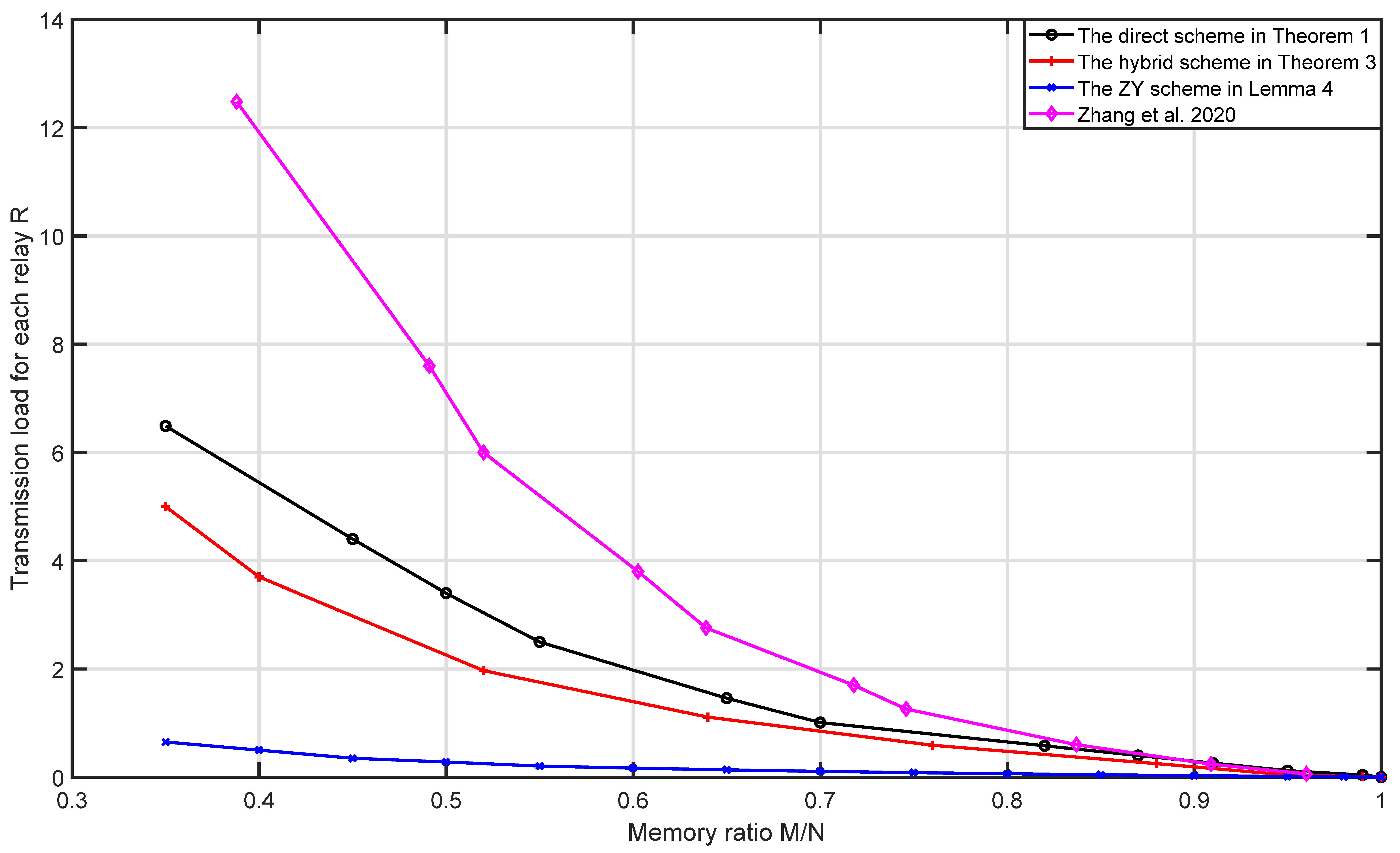
4.2. Numerical Comparison

The numerical comparison of the direct scheme and the hybrid scheme with the ZY scheme is given in Table 3. It is easy to see from Table 3 that R T h 1 R Z Y ln F Z Y F T h 1 and R T h 3 R Z Y ln F Z Y F T h 3 , which coincides with the analytic comparison.
Finally, when H = 14 , r = 4 , u = 6 and K = u H r = 6006 , the memory–load and memory–subpacketization tradeoffs are given in Figure 2. From Figure 2, we can see that for the same number of users and memory ratio, the schemes with transmission load for each relay from small to large are the ZY scheme, the hybrid scheme, the direct scheme and the naive scheme. This is because ZY scheme fully utilizes the multicast opportunities among the users who are connected to the same relay, then its coded caching gain is the largest, so it has the minimum transmission load for each relay; the direct scheme and the naive scheme only utilize the multicast opportunities among the users who are connected to different sets of r relays, while omitting the multicast opportunities among the users who are connected to the same r relays; however, the direct scheme more efficiently utilizes the multicast opportunities among the users who are connected to different sets of r relays than the naive scheme, so the transmission load for each relay of the direct scheme is lower than that of the naive scheme; the hybrid scheme not only utilizes the multicast opportunities among the users who are connected to different sets of r relays as the direct scheme, but also utilizes the multicast opportunities among the users who are connected to the same r relays, so its transmission load for each relay is lower than that of the direct scheme. From Figure 2, we can see that for the same number of users and memory ratio, the schemes with subpacketization from small to large are the direct scheme, the naive scheme, the hybrid scheme and the ZY scheme. Therefore, the direct scheme and the hybrid scheme have significant advantages in subpacketization compared with the ZY scheme and have significant advantages in transmission load for each relay compared with the naive scheme. Moreover, the subpacketization of the direct scheme is lower than that of the naive scheme.

5. Conclusions

In this paper, we extended a traditional ( H , r ) combination network to an ( H , r , u ) multiaccess combination network, where each r relay connects u users jointly, and proposed three schemes for such a network, i.e., the ZY scheme, the direct scheme and the hybrid scheme. The transmission load for each relay of ZY scheme obtained from the idea in [5] is approximately 1 r of the transmission load of MN scheme, but its subpacketization exponentially increases with the number of users. The direct scheme obtained by a direct construction of CPDA has significant advantages in subpacketization compared with the ZY scheme, whereas the parameter u must be a combinational number. The hybrid scheme obtained by a hybrid construction of CPDA works for the arbitrary parameter u as well as has significant advantages in subpacketization compared with the ZY scheme. In addition, the direct scheme and the hybrid scheme have significant advantages in transmission load for each relay compared with the naive scheme, which is obtained by repeatedly using the scheme in [19] u times. Moreover, the subpacketization of the direct scheme is lower than that of the naive scheme.
It is worth noting that the hybrid construction is based on a given CPDA and PDA and the memory ratio of the resulting CPDA is greater than that of the original CPDA. It is of great significance to look for a direct construction of CPDA which works for the arbitrary parameter u.

Author Contributions

Conceptualization, L.H., J.W., M.C., Q.D. and B.Z.; methodology, L.H. and M.C.; validation, L.H. and M.C.; formal analysis, L.H. and J.W.; investigation, L.H. and J.W.; data curation, L.H.; writing—original draft preparation, L.H. and M.C.; writing—review and editing, L.H., M.C. and J.W.; supervision, M.C., J.W., Q.D. and B.Z. All authors have read and agreed to the published version of the manuscript.

Funding

This work was supported in part by the Natural Science Foundation of China under Grant (No.62061004, No.62076214), the Guangxi Natural Science Foundation (No.2021JJD170057, No.2021JJB110029, No.2021JJD170045), and in part by the Guangxi Bagui Scholar Teams for Innovation and Research Project, and the Guangxi Talent Highland Project of Big Data Intelligence and Application.

Institutional Review Board Statement

Not applicable.

Informed Consent Statement

Not applicable.

Data Availability Statement

Not applicable.

Conflicts of Interest

The authors declare no conflict of interest.

Abbreviations

The following abbreviations are used in this manuscript:
MNMaddah-Ali and Niesen
ZYZewail and Yener scheme
PDAPlacement Delivery Array
CPDACombinatorial Placement Delivery Array

Appendix A. Proof of Theorem 1

Proof. 
Let the array generated by Construction 1 be P = ( p f , k ) where f F and k K . For any nonstar entry ( e , C ) occurring in P , there exists some f F and k = ( T , b ) K such that p f , ( T , b ) = ( e , C ) . Let C = C 1 C 2 where C 1 is the subset of C such that f i = 0 for each i C 1 and C 2 is the subset of C such that f i = 1 for each i C 2 . Let | C 1 | = λ 1 , then | C 2 | = λ λ 1 since C 1 C 2 = . In addition, 0 λ 1 ω and 0 λ λ 1 r ω . This implies that max { 0 , λ r + ω } λ 1 min { λ , ω } . Let x = max { 0 , λ r + ω } and y = min { λ , ω } , then λ 1 [ x : y ] .
We will then prove that the array P satisfies the conditions of Definition 2. Let us consider C1 of Definition 1 first. For any column label k = ( T , b ) , without loss of generality, assume that b = ( b 1 , b 2 , , b r ) satisfying b 1 = b 2 = = b ω = 0 and b ω + 1 = = b r = 1 . Let T = { δ 1 , δ 2 , , δ r } with δ 1 < δ 2 < < δ r . From (3), there are
Z ¯ = λ 1 [ x : y ] ω λ 1 X 1 × r ω λ λ 1 X 2 × H r a ω + 2 λ 1 λ X 3
vectors f = ( f 1 , f 2 , , f H ) F satisfying d ( f | T , b ) = r λ , where X 1 is the number of subvectors f | { δ 1 , , δ ω } satisfying d ( f | { δ 1 , , δ ω } , b | [ 1 : ω ] ) = ω λ 1 ; X 2 is the number of subvectors f | { δ ω + 1 , , δ r } satisfying d ( f | { δ ω + 1 , , δ r } , b | [ ω + 1 : r ] ) = r ω ( λ λ 1 ) ; and X 3 is the number of subvectors f | [ H ] \ T satisfying wt ( f | [ H ] \ T ) = a ( ω λ 1 ) ( λ λ 1 ) = a ω + 2 λ 1 λ . Thus, there are Z = H a Z ¯ stars in each column. Therefore, the condition C1 holds.
For any two distinct entries, say p f , ( T , b ) and p f , ( T , b ) , assume that p f , ( T , b ) = p f , ( T , b ) = ( e , C ) . Denote
f = ( f 1 , f 2 , , f H ) , T = { δ 1 , δ 2 , , δ r } , b = ( b 1 , b 2 , , b r ) , f = ( f 1 , f 2 , , f H ) , T = { δ 1 , δ 2 , , δ r } , b = ( b 1 , b 2 , , b r ) .
If T = T , we have e | T = b = b from (3). Then, we have f = f since
e | [ H ] \ T = f | [ H ] \ T = f | [ H ] \ T , e | C = f | C = f | C , f | T \ C e | T \ C , f | T \ C e | T \ C .
This contradicts our hypothesis: it implies that for any r-relay set T [ H ] r , each non-star entry ( e , C ) in P occurs at most once in the columns k = ( T , b ) of P where b { 0 , 1 } r and wt ( b ) = r ω . Thus, the multicast opportunities among the users who are connected to the same r relays are not utilized. We therefore have T T , and then there must exist two distinct integers, say i, i [ H ] , satisfying i T \ C , i T and i T \ C , i T . Without loss of generality, assume that i = δ 1 and i = δ 1 . From Construction 1, we have f δ 1 b 1 = e δ 1 = f δ 1 and f δ 1 b 1 = e δ 1 = f δ 1 . From (3)–(5), we have C T T and f | C = b | C = e | C = f | C = b | C . Then, d ( f | T , b ) < r λ and d ( f | T , b ) < r λ hold since | C | = λ . We therefore have p f , ( T , b ) = p f , ( T , b ) = from (3). Clearly, f f holds. Thus, the condition C3 of Definition 1 holds.
Furthermore, this implies that each useful star p f , ( T , b ) = satisfies d ( f | T , b ) < r λ . In other words, each star p f , ( T , b ) = satisfying d ( f | T , b ) > r λ is useless. Similarly to (A1), there are exactly Z = λ [ 0 : λ 1 ] λ 1 [ x : y ] ω λ 1 × r ω λ λ 1 × H r a ω + 2 λ 1 λ vectors f F satisfying d ( f | T , b ) > r λ , where x = max { 0 , λ r + ω } and y = min { λ , ω } . Deleting the useless stars, there are exactly Z Z stars in each column.
For any non-star entry ( e , C ) occurring in P , assume that p f , ( T , b ) = ( e , C ) ; from Construction 1, we have C T , | C | = λ , e i = f i for each i C ( [ H ] \ T ) and e i f i for each i T \ C . Since C = C 1 C 2 where C 1 is the subset of C such that f i = 0 for each i C 1 , | C 1 | = λ 1 [ x : y ] and C 2 is the subset of C , such that f i = 1 for each i C 2 , we have w t ( f | C ) = λ λ 1 . Then, w t ( f | T \ C ) = ω λ 1 since w t ( b ) = r ω and d ( f | T , b ) = r λ . Thus, w t ( f | T ) = λ λ 1 + ω λ 1 and w t ( f | [ H ] \ T ) = a ( λ + ω 2 λ 1 ) since w t ( f ) = a . Since w t ( e | T ) = w t ( b ) = r ω and w t ( e | [ H ] \ T ) = w t ( f | [ H ] \ T ) = a ( λ + ω 2 λ 1 ) , we have w t ( e ) = r ω + a ( λ + ω 2 λ 1 ) = a + r 2 ω + 2 λ 1 λ .
For any λ 1 [ x : y ] and for each vector e with wt ( e ) = a + r 2 ω + 2 λ 1 λ , let us consider any possible coordinate sets C 1 and C 2 such that (1) each coordinate of e | C 1 is zero; (2) each coordinate of e | C 2 is one; and (3) | C 1 | = λ 1 and | C 2 | = λ λ 1 . Let C = C 1 C 2 . We will then prove that ( e , C ) occurs in P . Without loss of generality, assume that C 1 = [ 1 : λ 1 ] , C 2 = [ λ 1 + 1 : λ ] and e 1 = e 2 = = e λ 1 = 0 , e λ 1 + 1 = e λ 1 + 2 = = e λ = = e a + r 2 ω + 3 λ 1 λ = 1 and e a + r 2 ω + 3 λ 1 λ + 1 = e a + r 2 ω + 3 λ 1 λ + 2 = = e H = 0 . That is,
e = ( 0 , , 0 λ 1 , 1 , , 1 λ λ 1 , 1 , , 1 , a + r 2 ω + 3 λ 1 2 λ 0 , , 0 ) H ( a + r 2 ω + 3 λ 1 λ ) .
Define
T C = C T 1 T 2 | T 1 [ a + r 2 ω + 3 λ 1 λ + 1 : H ] ω λ 1 , T 2 [ λ + 1 : a + r 2 ω + 3 λ 1 λ ] r ω ( λ λ 1 ) .
It is easy to check that for any T = C T 1 T 2 T C , we have | T | = r , w t ( e | T ) = r ω and there is an H-dimensional vector f defined as
f i = 1 if i T 1 , 0 if i T 2 , e i otherwise
satisfying wt ( f ) = a , then f F , ( T , e | T ) K and d ( f | T , e | T ) = r λ . Consequently, we have p f , ( T , e | T ) = ( e , C ) by Construction 1.
Furthermore, ( e , C ) appears H ( a + r 2 ω + 3 λ 1 λ ) ω λ 1 a + r 2 ω + 3 λ 1 2 λ r ω ( λ λ 1 ) times in P . Since the intersection of any element of [ a + r 2 ω + 3 λ 1 λ + 1 : H ] ω λ 1 and any element of [ λ + 1 : a + r 2 ω + 3 λ 1 λ ] r ω ( λ λ 1 ) is empty, we have T T C T = C . This implies that the set I ( e , C ) = C . Recall that I ( e , C ) is the intersection of the first coordinate T of all column labels ( T , b ) satisfying that ( e , C ) appears in column ( T , b ) , i.e., I ( e , C ) = p f , ( T , b ) = ( e , C ) , f F , ( T , b ) K A ( T , b ) , where A ( T , b ) is the set of relays which connect user ( T , b ) . The condition C4 of Definition 2 holds.
From the above analysis, there are
S = λ 1 [ x : y ] H a + r 2 ω + 2 λ 1 λ H ( a + r 2 ω + 2 λ 1 λ ) λ 1 a + r 2 ω + 2 λ 1 λ λ λ 1
different non-star entries in P . The condition C2 of Definition 1 holds.
Hence, P is a CPDA with the parameters in Theorem 1. For each non-star entry ( e , C ) in P , since I ( e , C ) = C , we have | I ( e , C ) | = λ , which is a constant. We will then prove that for each relay h [ H ] , the number of I ( e , C ) containing h is also a constant. In fact, the number of I ( e , C ) containing relay h is exactly
λ 1 [ x : y ] H 1 a + r 2 ω + 2 λ 1 λ H ( a + r 2 ω + 2 λ 1 λ ) 1 λ 1 1 a + r 2 ω + 2 λ 1 λ λ λ 1 + λ 1 [ x : y ] H 1 a + r 2 ω + 2 λ 1 λ 1 H ( a + r 2 ω + 2 λ 1 λ ) λ 1 a + r 2 ω + 2 λ 1 λ 1 λ λ 1 1 = λ H λ 1 [ x : y ] H a + r 2 ω + 2 λ 1 λ H ( a + r 2 ω + 2 λ 1 λ ) λ 1 a + r 2 ω + 2 λ 1 λ λ λ 1 ,
which is also a constant. From Lemma 3, Theorem 1 is proved. □

Appendix B. Proof of Theorem 2

Proof. 
Firstly, we will prove that the array L generated by Construction 2 is a ( u K 2 H r , F 1 F 2 , Z 1 F 2 + ( F 1 Z 1 ) Z 2 , S 1 S 2 ) CPDA. Clearly, L is a u K 2 H r × F 1 F 2 array. Furthermore, each column of L has Z 1 F 2 + ( F 1 Z 1 ) Z 2 stars since each column of P has Z 1 stars and each column of A has Z 2 stars. There are S = S 1 S 2 integers in L since there are S 1 integers in P and there are S 2 integers in A . Conditions C1 and C2 of Definition 1 hold.
For any two distinct entries l ( j 1 , j 2 ) , ( k 1 , k 2 ) and l ( j 1 , j 2 ) , ( k 1 , k 2 ) , if l ( j 1 , j 2 ) , ( k 1 , k 2 ) = l ( j 1 , j 2 ) , ( k 1 , k 2 ) = s [ S ] , then all entries a j 2 , k 2 , a j 2 , k 2 , p j 1 , k 1 , p j 1 , k 1 are integers and s = a j 2 , k 2 + ( p j 1 , k 1 1 ) S 2 = a j 2 , k 2 + ( p j 1 , k 1 1 ) S 2 from (10). Since a j 2 , k 2 S 2 and a j 2 , k 2 S 2 , we have a j 2 , k 2 = a j 2 , k 2 [ S 2 ] and p j 1 , k 1 = p j 1 , k 1 [ S 1 ] . Then, from the definition of PDA and CPDA, we have that (1) either j 2 = j 2 , k 2 = k 2 or a j 2 , k 2 = a j 2 , k 2 = holds; (2) either j 1 = j 1 , k 1 = k 1 or p j 1 , k 1 = p j 1 , k 1 = holds. Since l ( j 1 , j 2 ) , ( k 1 , k 2 ) and l ( j 1 , j 2 ) , ( k 1 , k 2 ) are two distinct entries, j 2 = j 2 , k 2 = k 2 and j 1 = j 1 , k 1 = k 1 cannot hold simultaneously, which implies that either a j 2 , k 2 = a j 2 , k 2 = or p j 1 , k 1 = p j 1 , k 1 = holds. Consequently, we have l ( j 1 , j 2 ) , ( k 1 , k 2 ) = l ( j 1 , j 2 ) , ( k 1 , k 2 ) = from (10). The condition C3 of Definition 1 holds.
For any s [ S ] , assume that s appears g s times in L , say
l ( j 1 ( 1 ) , j 2 ( 1 ) ) , ( k 1 ( 1 ) , k 2 ( 1 ) ) = l ( j 1 ( 2 ) , j 2 ( 2 ) ) , ( k 1 ( 2 ) , k 2 ( 2 ) ) = = l ( j 1 ( g s ) , j 2 ( g s ) ) , ( k 1 ( g s ) , k 2 ( g s ) ) = s ,
then
p j 1 ( 1 ) , k 1 ( 1 ) = p j 1 ( 2 ) , k 1 ( 2 ) = = p j 1 ( g s ) , k 1 ( g s ) = s < s > S 2 S 2 + 1 s 1
from (10). Assume that k 1 ( μ ) = ( T μ , i μ ) for each μ [ g s ] , we have I s ( L ) = I s 1 ( P ) = μ [ g s ] T μ . Since P is a CPDA, from condition C4 of Definition 2, the set I s 1 ( P ) is not empty. Then, I s ( L ) is not empty and the condition C4 of Definition 2 holds. Hence, the array L is a ( K , F , Z , S ) = ( u K 2 H r , F 1 F 2 , Z 1 F 2 + ( F 1 Z 1 ) Z 2 , S 1 S 2 ) CPDA.
Secondly, if | I s 1 ( P ) | = μ is a constant for each s 1 [ S 1 ] and the number of I s 1 ( P ) containing h is a constant for each h [ H ] , say | { I s 1 ( P ) | h I s 1 ( P ) , s 1 [ S 1 ] } | = ν for each h [ H ] , then we have | I s ( L ) | = | I s 1 ( P ) | = μ for each s [ S 1 S 2 ] where s 1 = s < s > S 2 S 2 + 1 and | { I s ( L ) | h I s ( L ) , s [ S 1 S 2 ] } | = ν S 2 for each h [ H ] . If there are Z 1 useless stars in each column of P , there are Z 1 F 2 useless stars in each column of L . From Lemma 3, L leads to an ( H , r , u K 2 , M , N ) multiaccess combination network caching scheme with memory ratio M N = Z 1 F 2 + ( F 1 Z 1 ) Z 2 Z 1 F 2 F 1 F 2 Z 1 F 2 = Z 1 Z 1 F 1 Z 1 + 1 Z 1 Z 1 F 1 Z 1 Z 2 F 2 , subpacketization F = μ ( F 1 Z 1 ) F 2 and transmission load for each relay R = S 1 S 2 H ( F 1 Z 1 ) F 2 .□

References

  1. Maddah-Ali, M.A.; Niesen, U. Fundamental Limits of Caching. IEEE Trans. Informat. Theory 2014, 60, 2856–2867. [Google Scholar] [CrossRef] [Green Version]
  2. Wan, K.; Tuninetti, D.; Piantanida, P. An index coding approach to caching with uncoded cache placement. IEEE Trans. Informat. Theory 2020, 66, 1318–1332. [Google Scholar] [CrossRef]
  3. Yan, Q.; Cheng, M.; Tang, X.; Chen, Q. On the placement delivery array design for centralized coded caching scheme. IEEE Trans. Informat. Theory 2017, 63, 5821–5833. [Google Scholar] [CrossRef] [Green Version]
  4. Ji, M.; Wong, M.F.; Tulino, A.M.; Llorca, J.; Caire, G.; Effros, M.; Langberg, M. On the fundamental limits of caching in combination networks. In Proceedings of the 2015 IEEE 16th International Workshop on Signal Processing Advances in Wireless Communications (SPAWC), Stockholm, Sweden, 28 June–1 July 2015; pp. 695–699. [Google Scholar] [CrossRef]
  5. Zewail, A.A.; Yener, A. Coded caching for combination networks with cache-aided relays. In Proceedings of the 2017 IEEE ISIT, Aachen, Germany, 25–30 June 2017; pp. 2433–2437. [Google Scholar] [CrossRef]
  6. Wan, K.; Ji, M.; Piantanida, P.; Tuninetti, D. On the Benefits of Asymmetric Coded Cache Placement in Combination Networks with End-User Caches. In Proceedings of the 2018 IEEE ISIT, Vail, CO, USA, 17–22 June 2018; pp. 1550–1554. [Google Scholar] [CrossRef] [Green Version]
  7. Wan, K.; Ji, M.; Piantanida, P.; Tuninetti, D. Caching in Combination Networks: Novel Multicast Message Generation and Delivery by Leveraging the Network Topology. In Proceedings of the 2018 IEEE International Conference on Communications (ICC), Kansas City, MO, USA, 20–24 May 2018; pp. 1–6. [Google Scholar] [CrossRef] [Green Version]
  8. Wan, K.; Ji, M.; Piantanida, P.; Tuninetti, D. Combination Networks with Caches: Novel Inner and Outer Bounds with Uncoded Cache Placement. arXiv:1701.06884v1 [cs.IT] 24 Jan 2017. Available online: https://arxiv.org/abs/1701.06884v1 (accessed on 11 March 2022).
  9. Wan, K.; Tuninetti, D.; Piantanida, P.; Ji, M. On Combination Networks with Cache-aided Relays and Users. In Proceedings of the WSA 2018: 22nd International ITG Workshop on Smart Antennas, Bochum, Germany, 14–16 March 2018; pp. 1–7. [Google Scholar]
  10. Wan, K.; Tuninetti, D.; Ji, M.; Piantanida, P. A Novel Asymmetric Coded Placement in Combination Networks with End-User Caches. In Proceedings of the 2018 Information Theory and Applications Workshop (ITA), San Diego, CA, USA, 11–16 February 2018; pp. 1–5. [Google Scholar] [CrossRef] [Green Version]
  11. Elkordy, A.R.; Motahari, A.S.; Nafie, M.; G¨¹nd¨¹z, D. Cache-Aided Combination Networks With Interference. IEEE Trans. Wirel. Commun. 2020, 19, 148–161. [Google Scholar] [CrossRef]
  12. Yan, Q.; Wigger, M.; Yang, S. Placement Delivery Array Design for Combination Networks with Edge Caching. In Proceedings of the 2018 IEEE ISIT, Vail, CO, USA, 17–22 June 2018; pp. 1555–1559. [Google Scholar] [CrossRef] [Green Version]
  13. Cheng, M.; Li, J.; Tang, X.; Wei, R. Linear Coded Caching Scheme for Centralized Networks. IEEE Trans. Informat. Theory 2021, 67, 1732–1742. [Google Scholar] [CrossRef]
  14. Cheng, M.; Wang, J.; Zhong, X.; Wang, Q. A Framework of Constructing Placement Delivery Arrays for Centralized Coded Caching. IEEE Trans. Informat. Theory 2021, 67, 7121–7131. [Google Scholar] [CrossRef]
  15. Cheng, M.; Li, Y.; Zhong, X.; Wei, R. Improved Constructions of Coded Caching Schemes for Combination Networks. IEEE Trans. Commun. 2020, 68, 5965–5975. [Google Scholar] [CrossRef]
  16. Yan, Q.; Tang, X.; Chen, Q.; Cheng, M. Placement delivery array design through strong edge coloring of bipartite graphs. IEEE Commun. Lett. 2018, 22, 236–239. [Google Scholar] [CrossRef] [Green Version]
  17. Quinn, J.J.; Benjamin, A.T. Strong chromatic index of subset graphs. J. Graph Theory 1997, 24, 267–273. [Google Scholar] [CrossRef]
  18. Zhang, Q.; Zheng, L.; Cheng, M.; Chen, Q. On the Dynamic Centralized Coded Caching Design. IEEE Trans. Commun. 2020, 68, 2118–2128. [Google Scholar] [CrossRef] [Green Version]
  19. Zhang, M.; Cheng, M.; Wang, J.; Zhong, X.; Chen, Y. Improving Placement Delivery Array Coded Caching Schemes With Coded Placement. IEEE Access 2020, 8, 217456–217462. [Google Scholar] [CrossRef]
  20. van Lint, J.H. Introduction to Coding Theory; Springer: Berlin/Helderburg, Germany, 1999. [Google Scholar]
Figure 1. A multiaccess combination network with H = 4 , r = 2 , u = 2 .
Information 13 00191 g001
Figure 2. Comparison of the direct scheme and the hybrid scheme with the ZY scheme and the naive scheme when H = 14 , r = 4 , u = 6 .
Information 13 00191 g002aInformation 13 00191 g002b
Table 1. The ( 12 , 6 , 4 , 8 ) CPDA with H = 4 , a = r = 2 , ω = 1 and λ = 1 .
( T , b ) {1,2}{1,3}{1,4}{2,3}{2,4}{3,4}
f (0,1)(1,0)(0,1)(1,0)(0,1)(1,0)(0,1)(1,0)(0,1)(1,0)(0,1)(1,0)
(0,0,1,1)0111,11011,2********0001,40010,3
(0,1,0,1)**0111,11101,3****0001,40100,2**
(0,1,1,0)****0111,11110,40010,30100,2****
(1,0,0,1)****0001,41000,11011,21101,3****
(1,0,1,0)**0010,31000,1****1011,21110,4**
(1,1,0,0)0100,21000,1********1101,31110,4
Table 2. The ( 24 , 8 , 4 , 32 ) CPDA.
( T , b ) {1,2}{1,3}{1,4}{2,3}{2,4}{3,4}
f (0,0)(0,1)(1,0)(1,1)(0,0)(0,1)(1,0)(1,1)(0,0)(0,1)(1,0)(1,1)(0,0)(0,1)(1,0)(1,1)(0,0)(0,1)(1,0)(1,1)(0,0)(0,1)(1,0)(1,1)
(0,0,0,0)*0100,11000,2**0010,11000,3**0001,11000,4**0010,20100,3**0001,20100,4**0001,30010,4*
(0,0,1,1)*0111,11011,2*0001,1**1011,30010,1**1011,40001,2**0111,30010,2**0111,4*0001,40010,3*
(0,1,0,1)0001,1**1101,2*0111,11101,3*0100,1**1101,40001,3**0111,2*0001,40100,2*0100,3**0111,4
(0,1,1,0)0010,1**1110,20100,1**1110,3*0111,11110,4**0010,30100,2*0010,4**0111,20100,4**0111,3
(1,0,0,1)0001,2**1101,10001,3**1011,1*0001,41000,1**1011,21101,3*1000,2**1101,41000,3**1011,4
(1,0,1,0)0010,2**1110,1*0010,31000,1*0010,4**1011,11000,2**1110,3*1011,21110,4*1000,4**1011,3
(1,1,0,0)*0100,21000,1*0100,3**1110,10100,4**1101,11000,3**1110,21000,4**1101,2*1101,31110,4*
(1,1,1,1)*0111,21011,1**0111,31101,1**0111,41110,1**1011,31101,2**1011,41110,2**1101,41110,3*
Table 3. Numerical comparison of the direct scheme and the hybrid scheme when ω = 1 , λ = 1 with the ZY scheme.
( H , r , a ) K M N R T h 1 R Z Y ln F Z Y F T h 1
15,2,42100.271.5911.75
16,3,416800.438.19297.35
18,3,624480.505.98391.00
20,3,1234200.564.03487.29
( H , r , a , K 2 , t 2 ) K M N R T h 3 R Z Y ln F Z Y F T h 3
20,3,3,8,127,3600.3853.68474.64
20,3,3,6,120,5200.4143.39484.46
20,3,3,5,117,1000.4338.24490.37
20,3,3,3,110,2600.5327.95497.17
Publisher’s Note: MDPI stays neutral with regard to jurisdictional claims in published maps and institutional affiliations.

