Article

Analysis of SAP Log Data Based on Network Community Decomposition

1
Consulting 4U, 779 00 Olomouc, Czech Republic
2
Department of Computer Science, VSB—Technical University of Ostrava, 708 00 Ostrava-Poruba, Czech Republic
*
Author to whom correspondence should be addressed.
Information 2019, 10(3), 92; https://doi.org/10.3390/info10030092
Submission received: 27 January 2019 / Revised: 18 February 2019 / Accepted: 25 February 2019 / Published: 1 March 2019
(This article belongs to the Special Issue Computational Social Science)

Abstract

:
Information systems support and ensure the practical running of the most critical business processes. There exists (or can be reconstructed) a record (log) of the process running in the information system. Computer methods of data mining can be used for analysis of process data utilizing support techniques of machine learning and a complex network analysis. The analysis is usually provided based on quantitative parameters of the running process of the information system. It is not so usual to analyze behavior of the participants of the running process from the process log. Here, we show how data and process mining methods can be used for analyzing the running process and how participants behavior can be analyzed from the process log using network (community or cluster) analyses in the constructed complex network from the SAP business process log. This approach constructs a complex network from the process log in a given context and then finds communities or patterns in this network. Found communities or patterns are analyzed using knowledge of the business process and the environment in which the process operates. The results demonstrate the possibility to cover up not only the quantitative but also the qualitative relations (e.g., hidden behavior of participants) using the process log and specific knowledge of the business case.

1. Introduction

Information system SAP is a world leader in the field of the enterprise resource planning (ERP) software and related enterprise applications. This ERP system enables customers to run their business processes, including accounting, purchase, sales, production, human resources, and finance, in an integrated environment. The running information system registers and manages simple tasks interconnected to complex business processes, users, and their activities, which are integral parts of such processes. The system provides a digital footprint of its run as it logs on more levels. When companies use such complex information systems, this software must also support their managers to have enough information for their decisions. What they can obtain from the actual information systems is usually information of quantitative types, e.g., “how many”, “how long”, “who”, “what”. Data from SAP ERP system is usually analyzed using data warehouse info cubes (OLAP technology—Online Analytical Processing). Data mining procedures also exist in SAP NetWeaver (Business warehouse, SAP Predictive Analytics), which work with such quantitative parameters. However, participants (users, vendors, customers, etc.) are connected by formal and informal relationships, and sharing their knowledge, their processes, and their behaviors can show certain common features that are not seen in hard numbers (behavior patterns). We are interested in analyzing such features, and our strategy is to analyze models using qualitative analysis with necessary domain knowledge; a similar approach can be used for the classification of unseen/new data instances.
Data received from logs contain technical parameters provided by the business process and a running information system. The goal of our work is to prepare data for management’s decision support in an intelligible format with no requirements to users for in-depth knowledge of data analysis but with the use of manager’s in-depth domain knowledge. A proper method to do this is visualization. However, visualization of a large network may suffer by the fact that such a network contains too much data and users may be misled. Subsequently, the aim is to decompose the whole into smaller, consistent parts so that they are more comprehensible and eventually (if it makes sense) repeat the decomposition. By comprehensibility, it is meant that the smaller unit more precisely describes the data it contains and its properties.
The idea to analyze process data was used already in earlier works. Authors in [1,2,3] construct a social network from the process log and utilize the fact that the process logs generally contain information about users executing the process steps. Our approach is more general, as we analyze patterns in a network constructed from complex attributes.
The conversion of object-attribute representation to the network (graph) and subsequent analysis of this network is used in various recent approaches. In particular, a network is a tool that provides an understandable visualization that helps to understand the internal structure of data and to formulate hypotheses associated with further analysis, such as data clustering or classification. Bothorel et al. provide in [4] a literature survey on attributed graphs, presenting recent research results in a uniform way, characterizing the main existing clustering methods and highlighting their conceptual differences. All the aspects mentioned in this article highlight different levels of increasing complexity that must be taken into account when various sets and number of attributes are considered due to network construction. Liu et al. in [5] present a system called Ploceus that offers a general approach for performing multidimensional and multilevel network-based visual analysis on multivariate tabular data. The presented system supports flexible construction and transformation of networks through a direct manipulation interface and integrates dynamic network manipulation with visual exploration. In [6], van den Elzen and Jarke J. van Wijk focus on exploration and analysis of the network topology based on the multivariate data. This approach tightly couples structural and multivariate analysis. In general, the basic problem of using attributes due network construction from tabular data is finding a way to retain the essential properties of transformed data. There are some simple methods often based on ε-radius and k-nearest neighbors. One of the known and well working approaches based on the nearest neighbor analysis was published by Huttenhower et al. in [7]. In this approach, in addition to the graph construction, the main objective is to find strongly interconnected clusters in the data. However, the method assumes that the user must specify the number of nearest neighbors with which the algorithm works. Methods using the principle based on the use of k-nearest neighbors are referred to as the k-NN networks and assume the k parameter to be a previously known value.
In our approach, we use the LRNet algorithm published by Ochodkova et al. [8]. This method is also based on the nearest neighbor analysis; however, it uses a different number of neighbors for different nodes. The number of neighbors is based on analysis of representativeness as described by Zehnalova et al. in [9]. In comparison with other network construction methods, the LRNet method does not use any parameter for the construction except a similarity measure. Moreover, networks resulting from the application of the LRNet method have properties observed in real-world networks, e.g., small-world and scale-freeness.
This work formulates and develops a methodology that covers selecting a proper log from the SAP application, data integration, pre-processing and transformation, data and network mining with the following interpretation and decision support. Real data and network analysis from the experiment is presented in Appendix A.

2. Materials and Methods

The first group of methods covers the transformation of logs from the real SAP business process run into the Object–Attribute table/vector. This group of methods contains a selection of proper logs and their integration, pre-processing, and transformation.
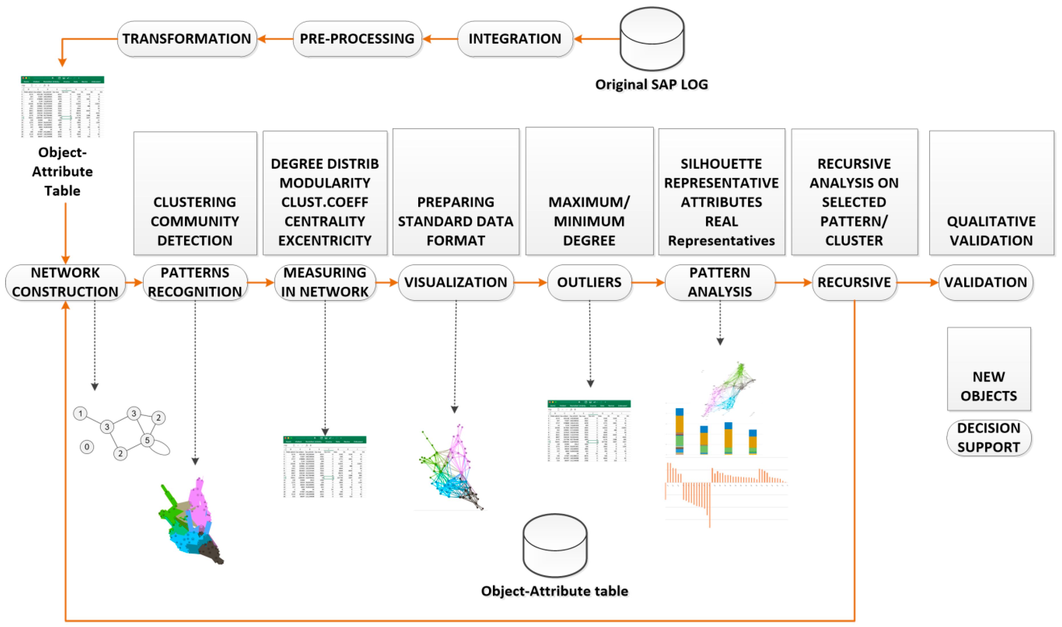
Integration. The proper logs and methods of change documents are selected—there are several in log sources in SAP systems, usually more of them are used as a data source for the original SAP LOG shown in Figure 1. A list of the most often used data LOG sources is presented in Appendix A.
Pre-processing uses several procedures described in Section 3.1 (cleaning, extension, anonymization).
Transformation generates final Object–Attribute table as is described in Section 3.1.
Core data of logging is based on the Case–Event principle. The case represents one complete pass of the process, and the event represents one step/activity related to the specific case. The requested object for the following analysis is selected (objects user, vendor, invoice participating in the process of vendor invoice verification). Attributes of the analyzed objects are selected from the source log, and new attributes are defined (and calculated) that can help to describe the objects’ behavior. The final anonymized and normalized Object–Attribute table for the next data mining analysis is prepared.
The transformation of the Object–Attribute table into a network and community detection is done following used methods. As mentioned above, we use the LRNet [8] algorithm by utilizing local representativeness for the vector–network transformation and the Louvain method of community detection [10]. The network and the detected communities are measured and analyzed. Visualization provides a fast user-accepting tool for recognition of specific situations and relations in the network. We utilize several network measures that we use for analyzing network parameters and communities—silhouette (the quality of clustering), modularity (a potential for division into communities), and centralities (eccentricity distribution). We identify two types of outliers, network outliers and attribute outliers.
Communities are identified as we showed above. Common characteristics of the nodes of specific communities are considered as patterns. Every pattern provides information containing a combination of value mix of profile attributes. We apply methods of statistical analysis to these patterns’ attributes. This mix of values for all the patterns provides a model. A representative participant can be found for each pattern (vector of attributes calculated as the average of relevant attributes of all cluster participants). The analysis is performed for the participants similarly with a representative on one side and typically non-conforming participants of the cluster on the other side. The participants can be distributed by their conformity with the model attributes.
The found communities are assessed, and communities with suitable parameters are used for decomposition. A recursive analysis is run on all identified clusters when average silhouette and modularity of detected clusters are high. In a case where the average silhouette of clusters is near zero or negative, we do not continue with the recursive analysis. The process, starting with network construction and ending with decomposition, is schematically described in Figure 1.
We use a qualitative validation and an interpretation based on domain knowledge. Evaluation of patterns, communities, and outliers in the real organization environment provides a validation of the found results. As we dispose of all information about source objects and relations with knowledge about the original environment, we prepare an interpretation of the received model and its patterns.
We work with a method of manual qualitative validation for decision support, and results from data mining are compared with the real environment of running business processes. This qualitative assessment serves as verification of results from data mining. It uses identified patterns from the original dataset. When a new object appears, we can compare this object with all identified patterns and find the most fitting pattern for the new object. Then, a comparison of attributes can be performed, and it can be analyzed if the behavior of a new object also fits the behavior of the found pattern. Another kind of qualitative validation is performed for finding the original records for the pattern for an extended/reduced original dataset.
The pre-processed log is prepared in the Object–Attribute format, where attributes are prepared into a numerical format. We use the Euclidean distance for a similarity function to measure the similarity more easily. The issue is that data in a vector format in high dimension cannot be effectively visualized. As much as we would like to visualize the data and results for managers, we decide to transform the initial Object–Attribute table into a network.

2.1. Construction of Network and Clusters Identification

The method used for a network construction is presented in [8]. As was mentioned, we use the Louvain method of community detection [10]. The network construction is based on a method [7] for the nearest neighbor analysis where the nearest neighbors must be specified and known. The used method uses the nearest neighbors in another way. Representativeness of source objects (and potential graph vertices) is used, and we expect that the objects have different representativeness. The representativeness is a local property based on the number of objects (e.g., the nearest neighbors of a selected node).
Edges between all pairs of the nearest neighbors are created first, then additional edges between the individual data objects in the number proportional to the representativeness of these objects are created. The representativeness of nodes in the constructed graph then corresponds approximately to the representativeness of the objects in the data. This forms a natural graph representation of the original data, which preserves their local properties.
The used algorithm implemented by [8] runs in the following steps:
  • Create the similarity matrix S of the dataset D.
  • Calculate the representativeness of all objects Oi.
  • Create the set V of nodes of the graph G so that node vi of the graph G represents object Oi of the dataset D.
  • Create the set of edges E of the graph G so that E contains the edge eij between the nodes vi and vj ( i j ) if Oj is the nearest neighbor of Oi or Oj is the representative neighbor of Oi.
  • The time complexity of the algorithm is O(|D|2).

2.2. Representative of Cluster—Patterns

Patterns are identified by the cluster analysis. A following statistical analysis is done on vectors that are members of identified clusters. Normalized average values of coordinates of every cluster member define a representation (representative vector) of the given cluster.
Let X = {x1, x2, …, xn}, xk = {xk1, xk2, …, xkm} Rm be an original dataset, where n is the number of records, and m is the number of inspected attributes for every record.
Let every cluster Pj contain n j original objects, Pj = {y1, …, ynj}, where i { 1 , , n j } ; y i X , yi = {yi1, yi2, …, yim}.
  • The vector of maximal values in every attribute is calculated: xmax = {max1, max2, …, maxm}.
  • Table Tj of normalized average values (Table 1) is calculated for every cluster j, where Tj = {tjA, tjB, tj1, cj1, tj2, cj2 …, tjm, cjm}
  • For cluster = 1 to j repeat steps 4–7
  • tjA is set as ID of pattern (= j)
  • tjB is set as number of members in pattern Pj = n j
  • representative vector (tj1 tjm) for cluster j is calculated: w { 1 , , m } ; t j w = 1 n j m a x w i = 1 n j y i w
  • confidence interval CI95 of every attribute i in cluster j is calculated: cji
Values t j w are normalized by each column (attribute) separately against the maximal value of a given attribute in the whole dataset, thus they can be visualized in one picture. Following Table 1, we show the cluster representatives and their confidential intervals CI95 of the experiment run for the dataset D1. Types of attributes are described in Table 2 and the attributes descriptions can be found in Table 3. Only the first four attributes and their confidence intervals are shown in Table 1. The complete table is shown in Appendix A in Table A1.
These representative vectors of the patterns and the confidence intervals shown in Table 1 provide a tabular and a visual view of the patterns model. The description model of patterns serves analytics who understand how patterns are constructed (it shows parameters of pattern representatives).

2.3. Detection of the Attribute Outliers

The interquartile range (IQR) is a measure of the spread of a distribution. The IQR is the difference between the 75th and the 25th percentile [11] or between the upper and the lower quartile [12]. In statistics, quantiles are limits splitting the range of a probability distribution into unbroken intervals with equal probabilities or dividing the observations in a sample in the same way. It means we have n − 1 quantiles dividing the distribution into n intervals. A quartile is a type of quantile—quartiles are the three limits that divide our dataset into four equally sized groups.
The first quartile (Q1) is defined as the middle number between the smallest number and the median of the dataset. The second quartile (Q2) is the median of the dataset. The third quartile (Q3) is the middle value between the median and the highest value of the dataset. IQR is calculated as IQR = Q3 − Q1. The interquartile range is often used to find outliers in data. The outliers that we work with are defined as observations whose values may be below Q1 − 1.5 × IQR or above Q3 + 1.5 × IQR.

2.4. Pattern Analysis

Pattern analysis is done by a statistical analysis of found patterns. Every pattern provides information containing a combination of value mix of profile parameters (attributes). This mix of values from all patterns provides a model. The model describes found clusters by attributes’ values. A representative participant can be found for every pattern. This pattern is afterwards defined by this representative vector of attributes. The analysis is done for participants very similarly to a representative on the one site, and typically non-conforming participants of the cluster is done on the other site. The participants can be distributed by the conformance with the model attributes. We are also interested in the outliers, as they represent a unique behavior (they can excel or simply differentiate and can represent risk or chance). We use two methods of outliers’ detection—network outliers (they are detected as isolated nodes with no edges to other nodes) and attribute outliers (they are detected by outliers of distribution given by a selected attribute, for example, by a quantile method).
A detailed analysis of an interesting cluster is also used. We repeat the clustering for the only participant of the selected cluster (with the same attributes). It eliminates the influence of the participants from other clusters.

2.5. Visualization

As mentioned before, visualization is an essential possibility in networks. We utilize several visualization concepts, as the target of using this approach is to support decision-making for managers (visualization is a valuable supporting tool):
visualization of clusters and relations in a network using Gephi software tool [13],
visualization of the pattern model,
distribution of participants inside clusters.
An interpretation also provides an important confirmation of analyzed results based on a comparison with the real environment. We always come back to the original business process and compare analytics results from an analysis with reality (confirm, find if analyzed result reflects some reasonable situation, constellation).

2.6. Model for Back Analysis of Objects from Patterns

As we have shown, we can identify the set of patterns P1, P2,…, Pd from the original dataset X = {x1, x2, …, xn}, xk = {xk1, xk2, …, xkm} ∈ Rm. In the carried experiment, there is X = D1. We can identify what representation of the pattern is in the real environment of the business process. The dataset X is defined as an Object–Attribute table (vector of attributes), where attributes are calculated from the context of a business process and from the log of the business process that provided the data for the initial log.
Every pattern Pj is defined by the representative vector Tj = {tjA, tjB, tj1 …, tjm}. This representative vector defines the meaning of parameters of the pattern members. It is important to perceive the pattern in both its features—first, as a set of the real representatives (in a given context) and second, as a set of descriptive rules (in our case, it is the representative vector). If we find the pattern in behavior of the business process (assumed to be in the range from time C1 to C2), it could be interesting to see such a pattern in a reduced or extended date/time range of the same business process in the same context.

2.6.1. Finding Original Records for Pattern from Original Dataset

First, we show how we can obtain the original record(s) from the same dataset D1 from the pattern Pr. We transform the original dataset X into the normalized dataset X′ = {x′1, x′2, …, x′n}, where:
x k j = x k j m a x j   ;   k { 1 , , n } ; j { 1 , , m }
(maxj is defined in Section 2.2).
We define the distance of the member xk of the dataset X′ from the pattern Pr as follows, where trj is representative of vector coordinates, and they are calculated as described in Section 2.2.
d ( x k , P r ) = j = 1 m ( x k j t r j ) 2 = j = 1 m ( x k j m a x j t r j ) 2
The most appropriate real object that represents the pattern Pr (or its representative vector) is found as xk, where d ( x k , P r ) is minimal. If the pattern Pr has i members, we can find i smallest d ( x k , P r ) .
We confirmed a good result of the concept presented in Section 2.6.1 when we tried to identify members of the patterns 1–11 by the presented concept. In the case of the patterns with one member, the correct user vector was identified in all cases. In the case of the patterns with more members, we found correct members (by minimal function).

Decision Support: Finding Pattern for New Object in Dataset

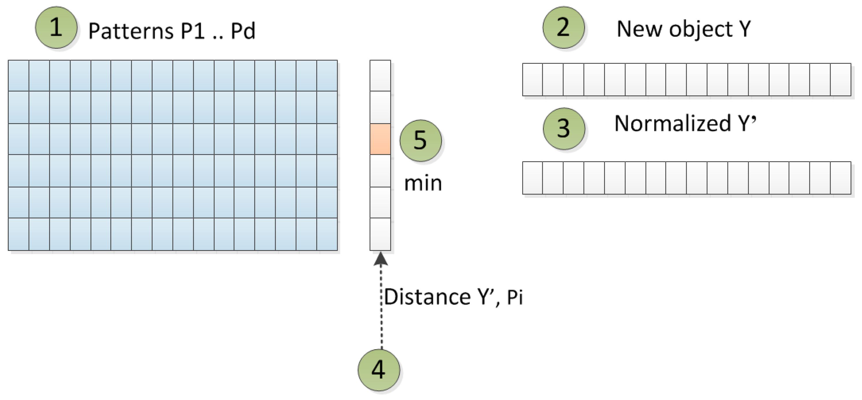
When the patterns P1, P2,…, Pd are identified from the original dataset, sometimes we need to analyze a new object yk = {yk1, yk2, …, ykm} ∈ Rm to know what pattern it fits the best and if the representative behavior also fits the pattern. The principle of the procedure is shown in Figure 2.
As in Section 2.2, we transform the original dataset X into the normalized dataset X′ = {x′1, x′2, …, x′n} (formula 1) and calculate maxi for all attributes. Then, we calculate the distance of the new object y′k normalized by the original dataset from every pattern P1, … Pd and find a pattern Pk with minimal distance d ( y k , P i ) ; i { 1 d } .
The distance d ( y k , P i ) is calculated by the same method as (2):
d ( y k , P i ) = j = 1 m ( y k j m a x j t i j ) 2
We confirmed a good result of the following concept of finding the original records for pattern from extended original dataset when we selected an existing user from the original dataset, and it fit the correct pattern (as we expected). Then, we collected data from the previous year for the user and we analyzed the distances of this new object to the patterns. The object fit the best with pattern 1. The representative parameters of pattern 1 were compared with representative values of this new object and consistency was found.

Finding Original Records for Pattern from Extended/Reduced Original Dataset

Next, we show how we can obtain the original record(s) from the dataset X1 from the pattern Pr, where X1 is a time-extended or a time-reduced dataset to the dataset X. A time-extended dataset means a dataset from the same business process but scanned (logged) during a wider time frame. A time-reduced dataset means a dataset from the same business process but scanned (logged) during a shorter time frame. The most appropriate real object(s) that represent(s) the pattern Pr is(are) found by the principle shown in Figure 3.
We expect that the pattern represents a given behavior, and this behavior can also be found in a reduced or an extended dataset. However, we must keep in mind that the pattern is defined by a set of attributes. An attribute can be representative (it describes property that represents a cluster, which is calculated as, for example, the mean of total process time of one case, mean of maximal or minimal time, or the number of used order types) or cumulative (it describes a value that is cumulative and directly depends on the number of records in a cluster—as an absolute number of activities or a number of used orders). We call some attributes marginal (if they represent a value of some margin or an extreme, for example, maximal/minimal value)—these attributes tend to be representative, but in large datasets, they can be easily changed by an extreme or an error record.
As the extended/reduced dataset covers another base of inspected activities (and objects as well), we can only consider attributes from patterns that we call representative, i.e., they are not dependent on the number of logged activities (if the process does not change). Also, representative attributes are presented in a normalized form, which means that in some case, they can be valid for the reduced or extended dataset.
We show used types of the attributes in the following Table 2 (R—representative, C—cumulative, M—marginal).

3. Experiments and Results

We performed experiments from fully anonymized real datasets. We present results from a behavior analysis of participating objects (users—dataset D1) in the process of an invoice verification. The analyzed sample contained 37,684 invoices (cases) in 171,831 steps (activities) running in the SAP workflow process of an invoice verification with 240 participating users and 3320 vendors. The analysis detected 11 patterns in the highest level; they were subsequently analyzed by decomposition. Outliers were found and analyzed (both network and attribute outliers). Outputs from the analysis were visualized and described.

3.1. Getting the SAP Log And Its Transformation

Data preparation was carried out based on the following processing steps:
  • The selection process selects log records meeting requested parameters
    IDOBJ type (object identification, e.g., vendor invoice number),
    task/activity type (e.g., set of workflow tasks representing steps in the observed process),
    time period (e.g., 2017/2018 year),
    organization structure (selected region if requested).
  • The cleaning process selects and updates records with the aim to have only the completed cases logged (delete any cases without start or end). It solves faulty values in some relevant columns, which are typically responsible person (blocked users without representation) and error status of work item.
  • The extension process typically finds more context data for observed object, data, or process and enriches the dataset by requested parameters (we used an extension for purchase order type, plant ID, etc.)
  • The anonymization process converts sensitive data in the dataset into numbers from a generated interval, thus no sensitive data exists in the processing. We used a tool for anonymization of the following data from datasets: username, organization structure, and vendor ID.
  • The binary evaluation of categorical attributes for some methods is run (by request) during the anonymization process. Attribute A is anonymized in the first step. Let the set of values of attribute A be f(A, k) = {A1, …, An}, let f(A, k) be the value of attribute A for log record k, let the set of anonymized values of attribute A be {VA1, …, VAn}. Then, n new columns (attributes) A1, …, An are created. We define the f(Ai, k) as the value of attribute Ai for the specific log record k: f ( A i ,   k ) = { 1   f ( A ,   k ) =   A i 0   e l s e .
  • The transformation to the Object–Attributes table generates a final table for specific analysis. For an analysis of users’ behavior, use Table 3.

3.2. Data Mining

The User–Attribute table is used as a source vector’s set for a transformation to a network. The main reason for using a network is the possibility of visualization of data structures and sub-structures based on a similarity relation (similarity of vectors from the data source). Transformation of an original data source into a network and a cluster construction was carried out using the algorithm described in Section 2.1. Attributes of the vector were constructed from the behavior of users during an invoice verification, and the whole vector represented a set of evaluated behavioral attributes.
An automatic clustering for a network enables one to find the most important clusters (groups) in the network. The quality of found clusters is checked by the silhouette of the clusters. Silhouette shows visually how stable the cluster members are in connection to its cluster.
Measuring network parameters helps to understand network behavior in some cases. An analysis of cluster parameters provides patterns of the specific clusters. Analysis of outliers identifies clusters with one member on the first level, and the outliers in specific clusters are identified.

3.2.1. Network and Patterns of D1

Here, we show the analysis and visualization done on dataset D1. A network was constructed, and several basic network parameters were measured as it is summarized in Table 4.
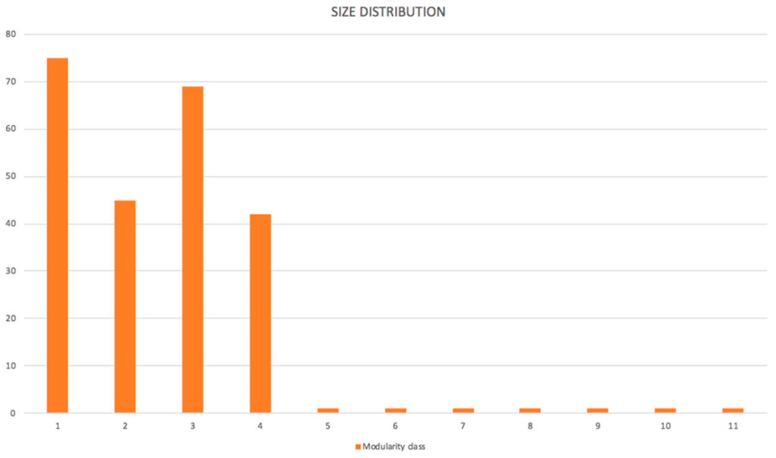
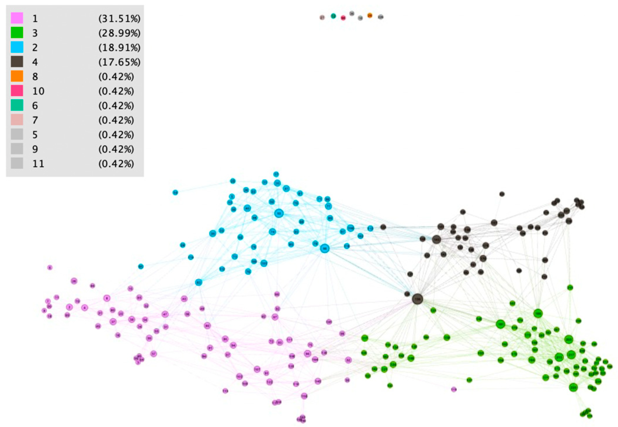
Eleven patterns were identified in a source dataset. Patterns with average values of all utilized attributes of their members are listed in Table A1 below. The vector of parameters in a specific row (patterns) defines representatives of each pattern. As can be seen from the pattern profiles table, four patterns contain more members (pattern 1–4), while other ones represent outliers (only one member in patterns).
We visualized the network using the Gephi visualization tool. Typically, the following visualization tools are used for output (shown in Figure 4):
Force Atlas method,
partitioning based on found patterns,
tanking by the degree,
extension of the result for visibility of requested detail.
We analyzed network outliers in constructed networks (users with degree = 0) and then patterns representing identified detected communities in more detail.
The result about outliers is summarized in the following Table 5 (results with > should be analyzed in detail in a real situation):
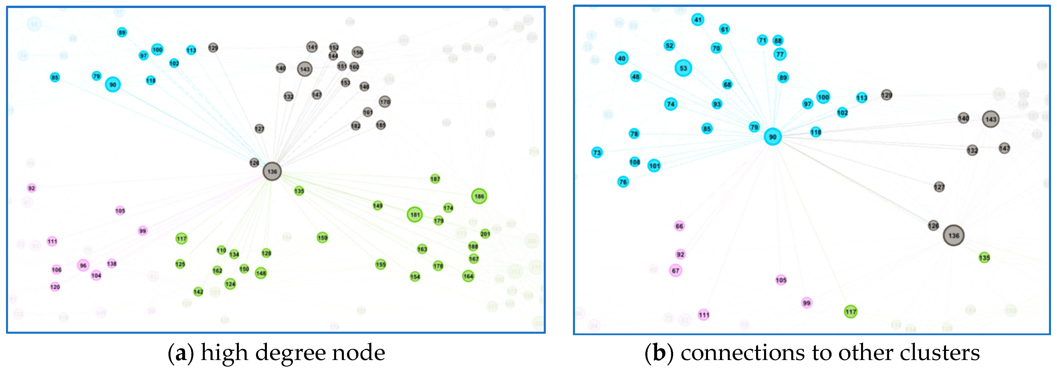
Note about the highest degree: typical users with the highest degree are also interconnected with neighbor clusters, and they are not typical clusters representatives (see Figure 5). Users from Supply chain, Invoice clerk, IT, and Customer service were found in the highest degree level.
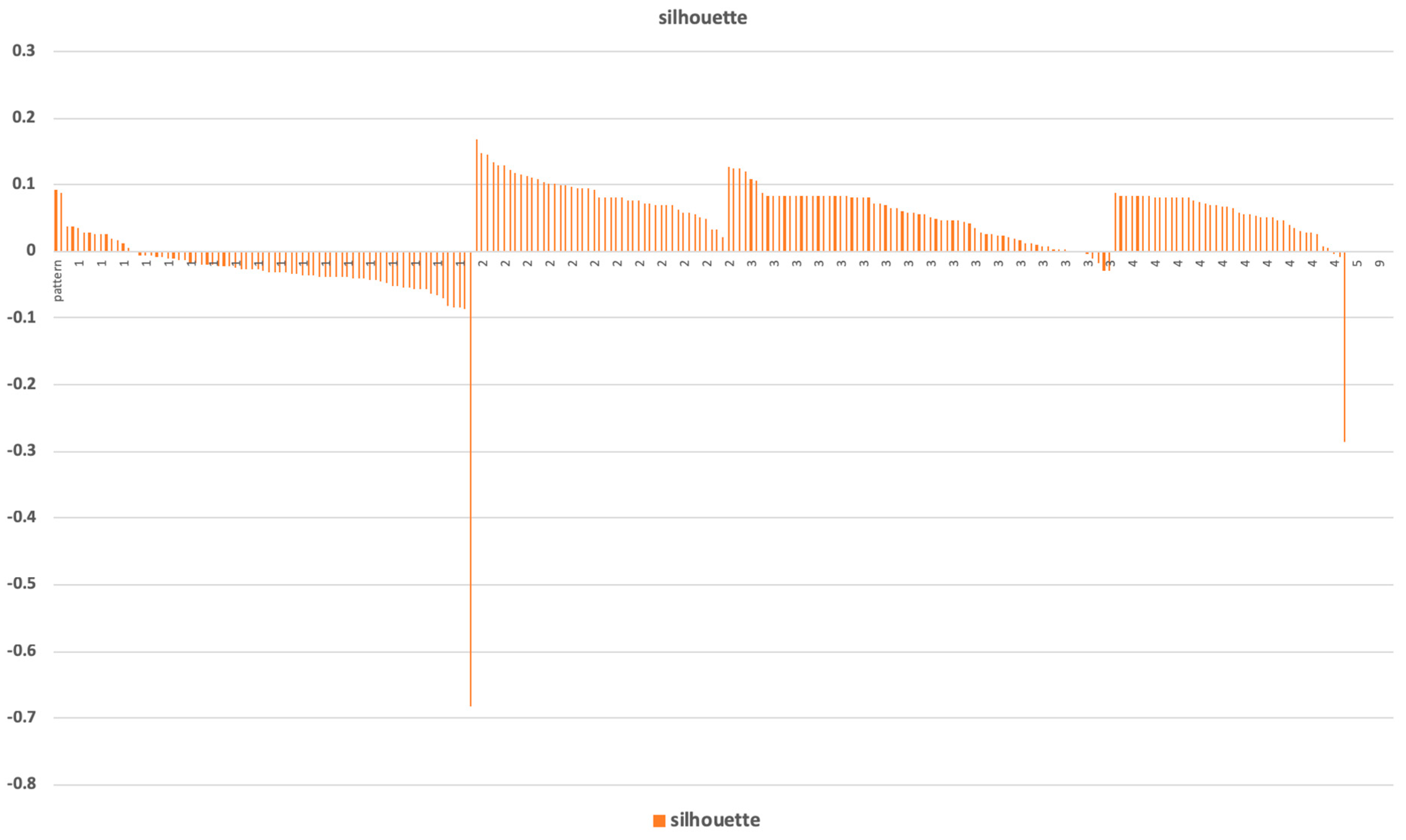
Pattern analysis was done for patterns 1–4 (patterns with more than one member). Silhouette of inspected clusters is visualized in Figure A1. Patterns were found by the cluster analysis, then the statistical analysis was done on vectors of the members of the clusters. Normalized average values of coordinates of every cluster member define representation (representative vector) of a given cluster—the background is explained in Section 2.2. Visualization of patterns representatives (Figure 6) provides a basic overview of the values of vector coordinates of a typical member in the pattern.
It is important now to describe the pattern representative behavior in the language of the source business situation (see Table 6) and to analyze a typical behavior of the pattern members, show the distribution of their behavior, and find details.

3.2.2. Understanding of Business Parameters of Patterns of D1

Here, we show (for explanation) how the analysis of Pattern 1 was done in detail. This part of the analysis could be done with domain knowledge. Pattern 1 is characterized by a high number of documents (orders, invoices), the call-off orders prevail, a very low average minimal time, and a high average maximal time but a low average time. A typical representative is a user processing the invoice of a regular vendor with many regular orders. Most of them are processed very fast on average, but some of them (possibly the first ones) are processed much longer. We identified and named the pattern by the language of the business environment. It is important when a user operates with such a pattern. We used the following approach for the detailed analysis inside the pattern (shown in pattern 1).

Distribution of Inspected Profile Attribute Value Inside Patterns

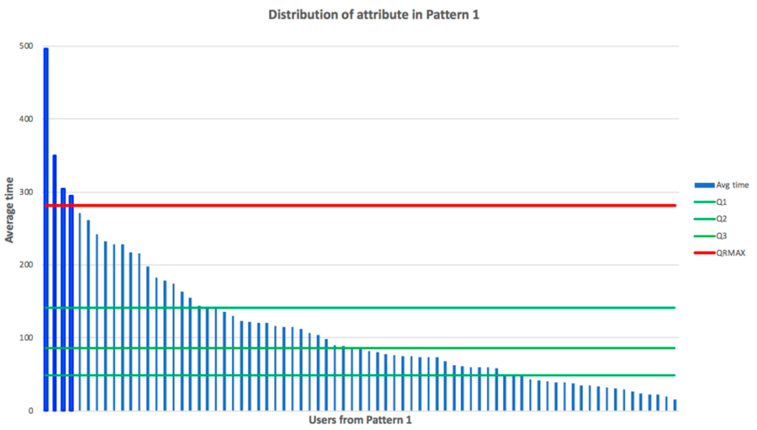
Let the average time be the inspected profile attribute. We see that the average time differs in specific patterns. We calculate now the distribution of the inspected value of average time and try to find attribute outliers using IQR. The result is shown in Figure 7.
In the next step, outliers are identified in this distribution using quartiles method. We calculate quartiles Q1, Q2, Q3 for the pattern 1 dataset, here Q1 = 48.8; Q2 = 86.7; Q3 = 141.8; IQR = Q3 − Q1 = 93; QRMIN = Q1 − 1.5 × IQR = −90.8; QRMAX = Q3 + 1.5 × IQR = 281.5. Records with an inspected value greater then QRMAX or less then QRMIN are identified as outliers.
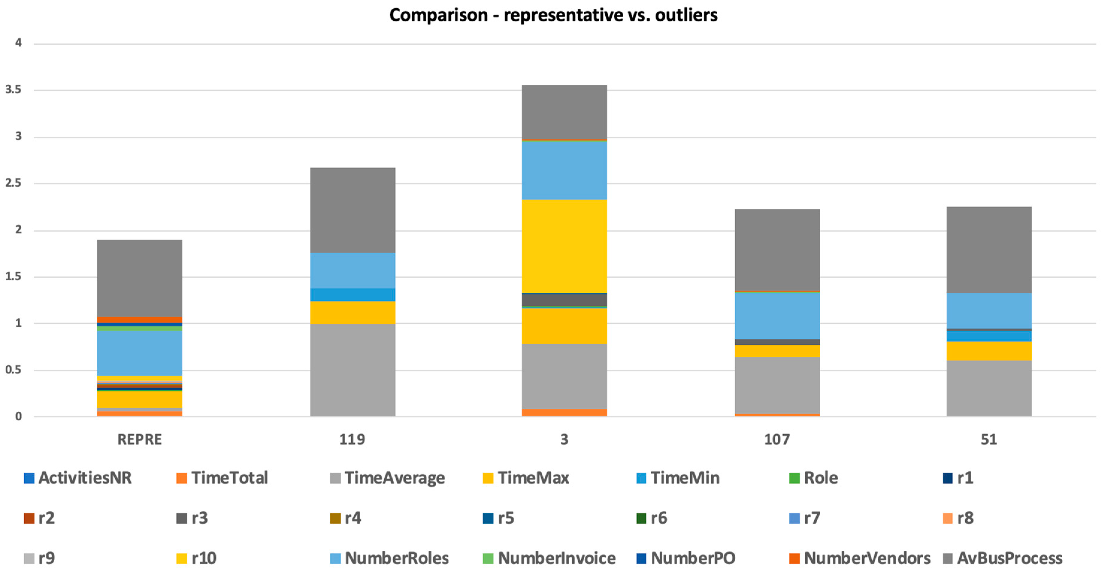
We found four outliers in this dataset—users 119, 3, 107, and 51—and all of them had average times greater then QRMAX. We analyzed these outliers, as they showed a different behavior than the rest of the participants in the observed pattern.

Analysis of Representative and Outliers of This Distribution

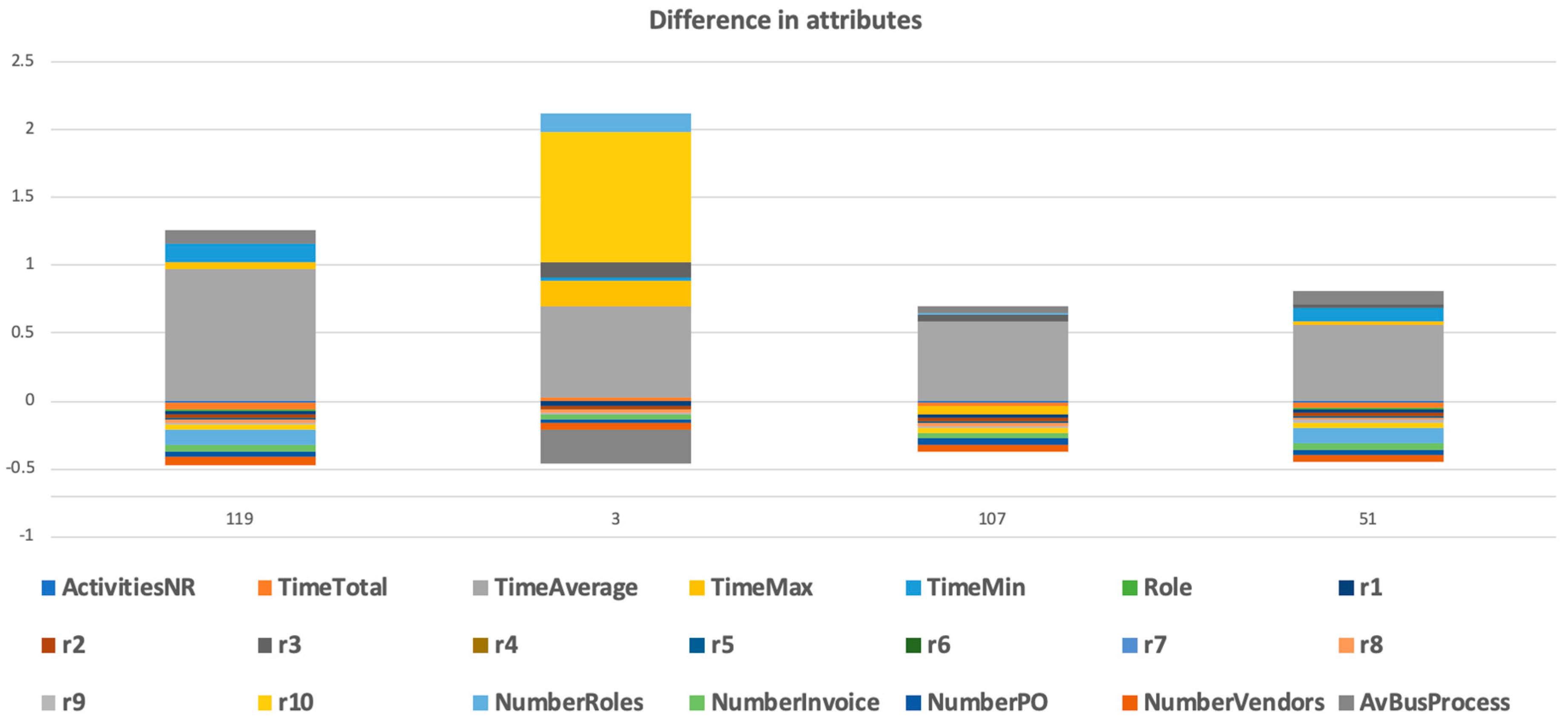
The outliers in the observed cluster can also be potentially interesting for a detailed inspection. We prepared a statistical analysis of the profile representative and all four outliers, as shown in Figure 8. Another support view can be seen in Figure 9, which shows the differences in outliers’ attributes in comparison to the representative of the given cluster.
The analysis of outliers from the given pattern using the difference of attributes provides a support tool for identification objects that are characterized by some non-conformity.
The same visual (graph) comparison we provide also shows table-based differences where we can analyze numeric values. One obvious difference there is the average time (the attribute on which outliers were identified) in cluster 1. More interesting is that we can see a special different behavior of the analyzed outlier named an attribute in Figure 9 (user 119 differs in attributes NumberRoles, TimeMin, AvBusProcess), (user 3 differs in attributes AvBusProcess, r10, TimeMax, NumberRoles), (107: TimeMax), (51: NumberRoles, TimeMin, AvBusProcess). This detailed analysis could be done for more attributes.

3.2.3. “Recursive” Analysis of Input Data from Specific Cluster of D1 (Dataset D2)

A recursive analysis is run on all the identified clusters while the average silhouette and modularity of identified clusters are high, which means that the cluster will potentially contain more sub-clusters. In a case where the average silhouette of clusters is near zero or negative, we do not continue with the recursive analysis.
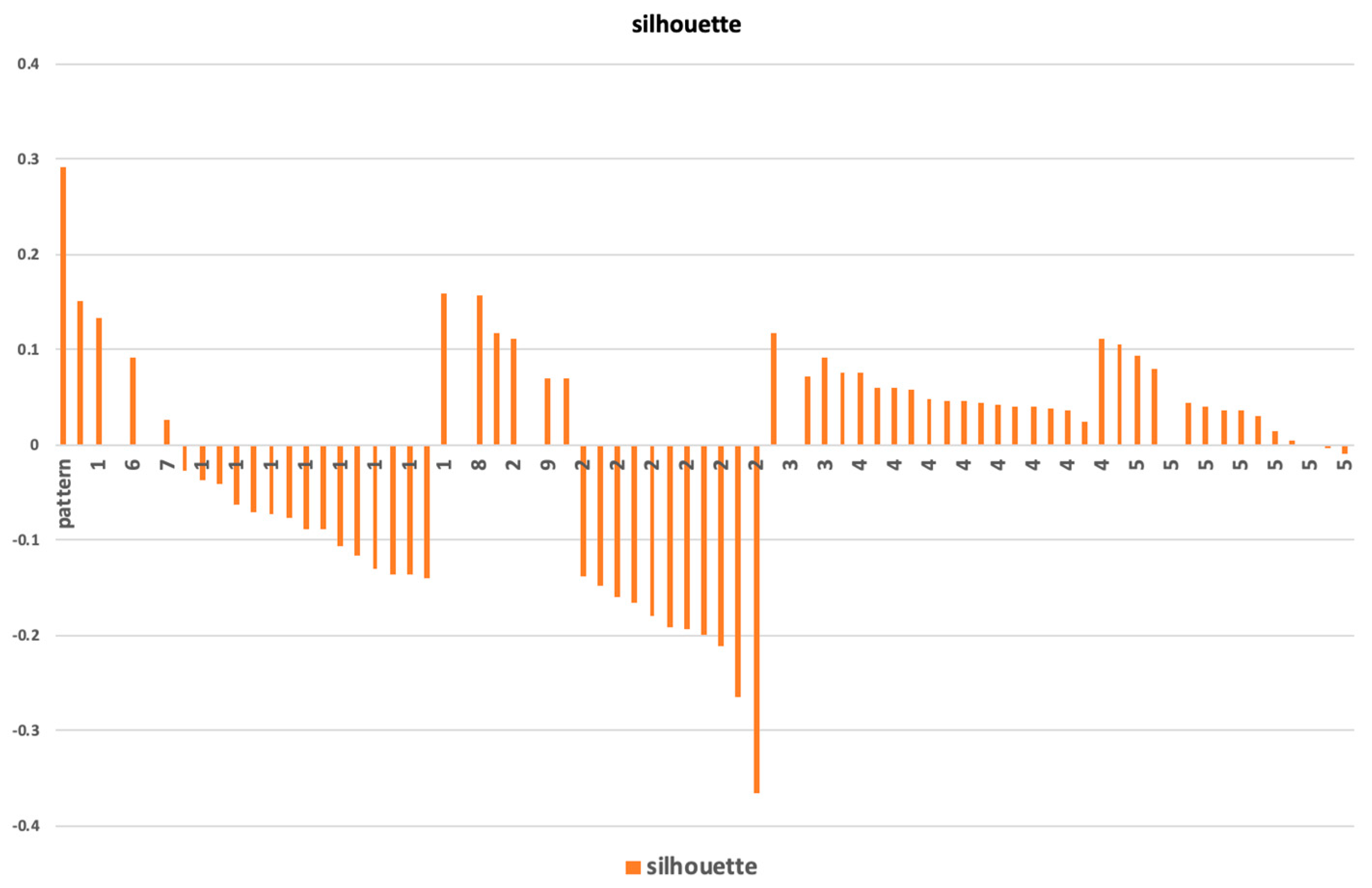
Here, we focus on cluster 1, which is not stable (seen from silhouette in Figure A1). A silhouette analysis shows that 80% of objects from pattern 1 have a silhouette with a negative value. It means that these objects are not connected to their own pattern 1 any more firmly than they are to neighboring clusters.
Returning to the initial dataset, we selected records identified in pattern 1 and started the data mining analysis on this dataset D2 in the same way as we did with D1. We do not show all the details from the recursive analysis results; only the result of the outliers’ analysis is presented here. Silhouette of the analysed network constructed from the dataset D1 is shown in Figure 10.
We analyzed the outliers in a network of the dataset D2 (users with degree = 0), users with the maximal degree, and other patterns in more detail; outliers are analysed in Table 7.
The patterns were found by the cluster analysis, then the statistical analysis was done on vectors of members of the clusters. Normalized average values of coordinates of every cluster member define representation (representative vector) of a given cluster. Visualization of patterns representatives (Figure 6) provides a basic overview of the values of vector coordinates of a typical member in the pattern.
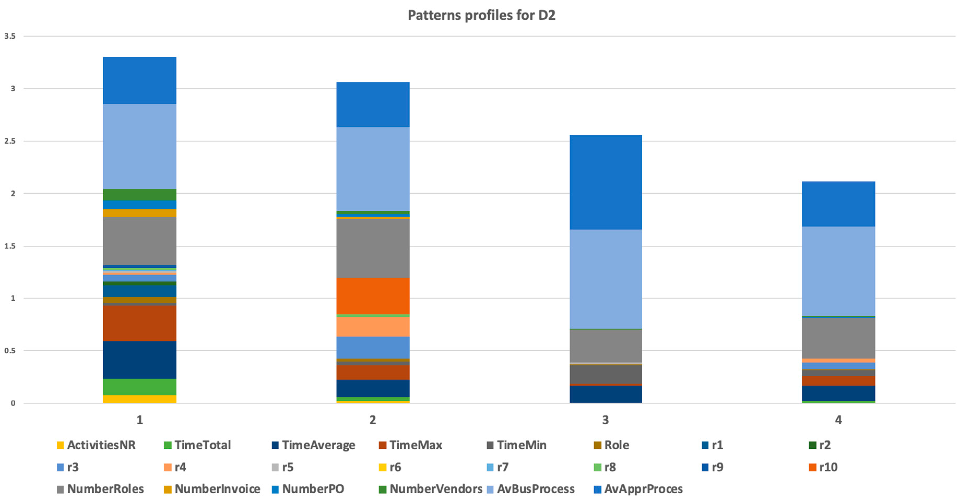
It is seen that representatives of the specific patterns of the dataset D2 (previously the cluster 1 of the dataset D1) is based on a set of parameters—the set and weight of parameters are visualized in the graphical representation in Figure 11 or in Table 8. We now describe the pattern representative behavior in a language of the source business situation and analyze a typical behavior of the pattern members, showing the distribution of their behavior and finding details. For comparison, we also show representatives.
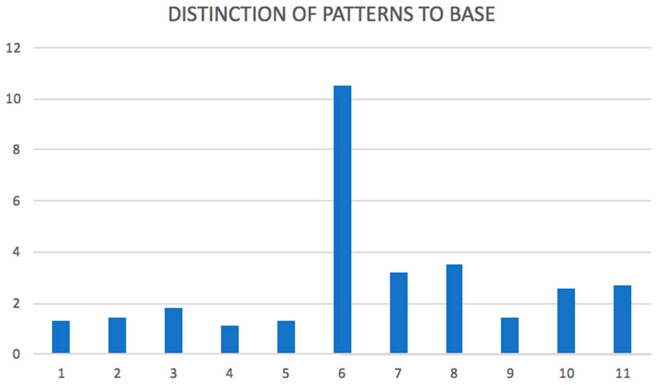
When the original pattern 1 from dataset D1 is a base, we analyze the distinction of specific sub-patterns in comparison to the base pattern. This distinction can be calculated as a difference between the representative vector and the representative vector of the original dataset. The simple sum of the distinction vector attributes provides us with the size of the distinction, as shown in the graph in Figure 12. As is seen, the most significant distinction is found for pattern 6. As was found above by another method, it is a typical outlier and verified in the real environment. Similarly, we could analyze the distinction of a specific attribute value between a specific sub-cluster and source cluster D1.

3.3. Finding Pattern for New Object in Dataset

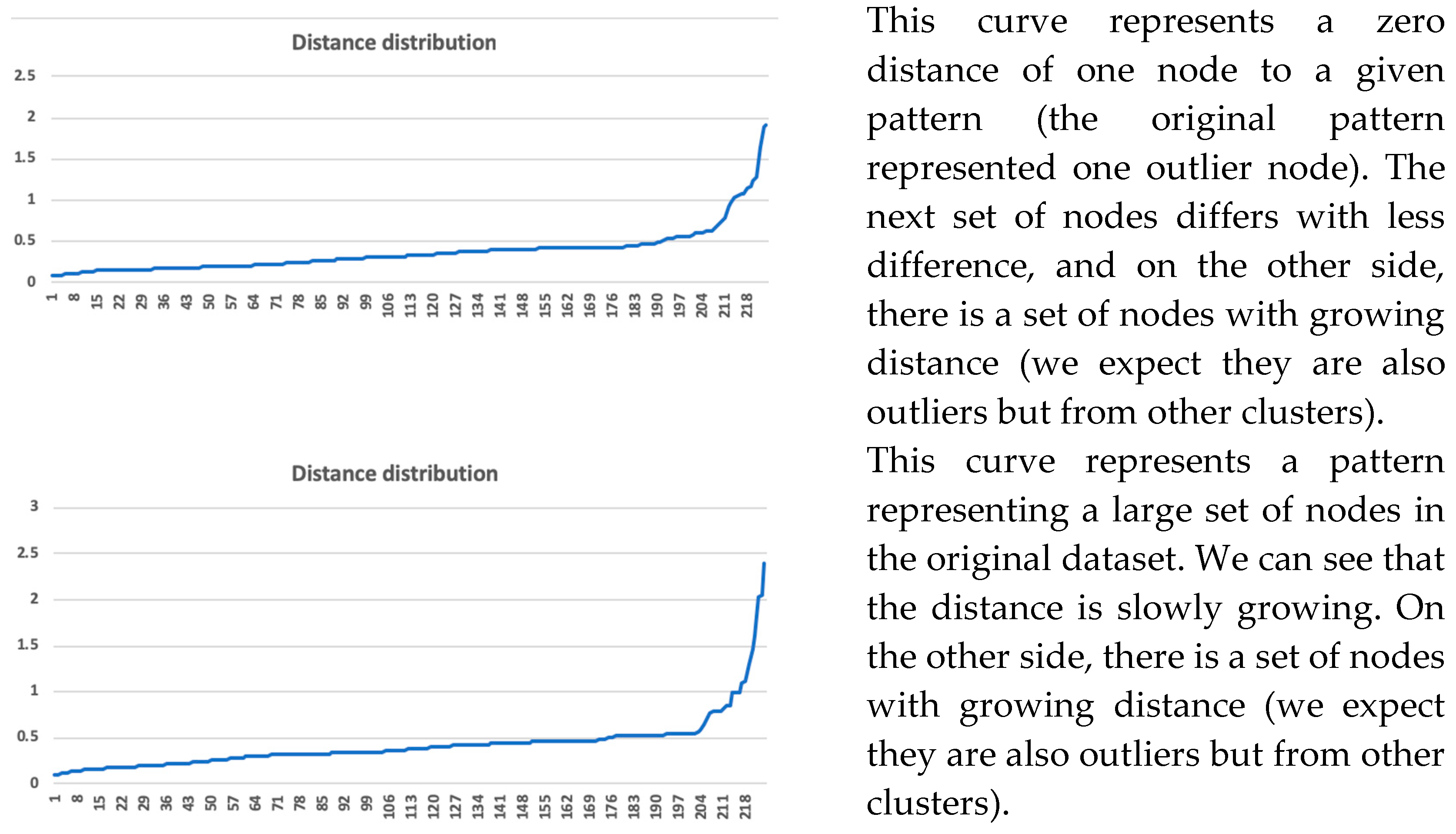
We experimentally used the dataset X1 that we constructed from the dataset D1 utilizing a filter for invoices only created in the 2017 year. The dataset X1 has 144,966 activities. We used the same procedure for finding the original record as explained in Section 2.6 for the dataset X1. All attributes of the used patterns were applied to this experiment. The analysis was done for all 11 patterns.
It did not matter if the pattern had one member or many members as long as the range of the distance where users were found was in the interval <0; 0.3>. Using the visual curve of the graph of distance distribution summarized in Section 2.6, we can meet two typical curves of the graph described in Figure 13.

4. Discussion

We presented the methodology of knowledge discovery from data that we used for data mining of logs generated from the SAP systems. Using this approach, we analyzed a specific business process (invoice verification) from the specific real environment, as was described in Section 3. We showed how the network was constructed, how patterns were found, and how they can be visualized and analyzed recursively.
The used method of network construction with following community detection has some known limitations in complexity; used algorithms have quadratic complexity O(n2) for the network construction, which is done by the representativeness computing. From this perspective, the method can be used for samples with limited size. On the other hand, for business processes with several hundred thousands of activities, the method works in an order of seconds and is still usable.
Another discussion was about visualization. We selected two dimensional visualization of the network to focus users with several factors—a local characteristic (node degree) was represented by the size of the node, and a network characteristic (community structure) was represented by the density of vertices in between the community. As managers prefer to accept a more straightforward message, improving the visualization method is still open for future work.
We also analyzed users with the high (or highest) degree. It turned out that such users were also interconnected with neighbor clusters and they were not typical clusters representatives. We identified types of such users, but no specific common behavior was found for high-degree users.
We can say that this method of network analysis identified a set of communities and a set of network outliers from a given data set. It was important to identify both kinds of sets. In our article, the network outliers were analyzed in Table 5 and Table 7, the pattern of found communities were described in Figure 6, Table 6 displays data source D1, and Figure 11 and Table 8 show data source D2. The finding should be taken back to the real implementation environment and manager or consultant with domain knowledge should identify what the significance or character of the outlier/pattern is. Specifically, we identified seven network outliers for data source D1, where five of them (11, 10, 8, 6, and 7) were special users, and we understood that they were outliers for this reason; two of them (5 and 9) should be analyzed in detail, because they had different behaviors than other users from their department. Our method revealed specific users that had different behaviors that were typical in a set of users with a similar organizational assignment. The other discussion could be about network patterns. We identified four communities (described by patterns) for data set D1. As was described in Section 3.2.2, domain knowledge could be used for the specification of attribute values mix. For example, pattern 1 represented users processing invoices of regular vendors with many regular orders. What could have been significant was if in the extended dataset, some regular vendor had its invoice verification process in other cluster/pattern. It could certainly be done by outbalancing another attribute, but this should be analyzed.
Every cluster pattern was calculated using a vector of attributes. We could focus on some attribute and see the distribution of the cluster participants based on such attribute, as we showed in Figure 7. We could see the outliers of this cluster (with a focus on selected attribute). We could visualize how these outliers differed in selected attributes and in a mix of attributes (Figure 8 and Figure 9).
The methodology contains steps for analyzing patterns in the real environment and running a recursive analysis of interesting patterns (e.g., unstable patterns or patterns with apparent exceptional participants, which could be a participant “far” from the representativeness of the pattern). The border of recursive processing of specific patterns could also be discussed. Our approach was to run recursive analysis while average silhouette and modularity of detected clusters were high. In a case where the average silhouette of clusters was near zero or negative, we did not continue with the recursive analysis.
We proved that the approach uncovered some patterns by found representativeness parameters that are typically present on this business process (number of roles, average time, etc.).
Another contribution is the finding that the pattern (as a combination of representativeness) can be used as a model for:
decision support for an assignment of a new object to an existing pattern with a possible comparison of representative attributes and the real behavior in an organization;
searching back to the original dataset or to a reduced/extended dataset (in this case, we suggest using only representative attributes) for showing the pattern representatives more quickly and for detailed inspection, which was proven back on the real datasets.
5. Conclusions

The suggested methodology shows the importance of visualization of the network and the community detection capability for decision support. Based on the presentation of the real results, it can be stated that the methodology can be projected into a real system for underpinning managerial decision-making over SAP data.
We presented how analysis of business process logs is run using network construction, community detection, and pattern identification for a detected community, as well as how network outliers are identified and how domain analyses on these patterns and outliers are done. We found the specific relevant outliers and communities from the data source that we identified by parameters from the environment that were not part of inspected attributes (hidden attributes). This meant that we identified the behavior of a given group of participants (members of the detected community) calculated from the mix of attributes.
The recursive procedure of analyzing the communities brought the possibility of uncovering not only different behaviors of the network outliers in the original network but also different behaviors of the attribute outliers in specific clusters, which could be also interesting for managers.
The analysis of outliers provided interesting results in the detection of the objects that were different from the usual behavior in the detected community (pattern). Additionally, the relevance of the approach is supported by the fact that the network partitioning to communities confirms expectations (for example, large contractors have clustered together even if their “size” is not present among the attributes used in the analysis, meaning they have some common behavior represented by a given combination of values of attributes).
We were then able to compare whether or not another new contractor of the same “size” was included in the same cluster (and if not, we could analyze why).
We also identified some interesting areas for future work—for example, method of visualization. There is another area for the future research, and it is universality. As the SAP system is universal, and used methods from this work are also universal, there is a potential for a compatible solution for any standard SAP solution.

Author Contributions

Individual authors cooperated on this article as follows: conceptualization was prepared by M.K. (Martin Kopka) and M.K. (Miloš Kudělka); the methodology was developed by M.K. (Martin Kopka); software on SAP framework was prepared by M.K. (Martin Kopka), network implementation was prepared by M.K. (Miloš Kudělka); validation with knowledge of process domain and investigation of the process was done by KO; writing—original draft preparation was done by M.K. (Martin Kopka); writing—review and editing was done by M.K. (Martin Kopka), M.K. (Miloš Kudělka).; visualization was solved by M.K. (Martin Kopka).

Funding

This research received no external funding.

Conflicts of Interest

The authors declare no conflict of interest.

Appendix A

Patterns and confidence intervals of result from experiment D1.
Table A1. Patterns—table of profile parameters and confidence intervals in experiment D1.
PATTERNCOUNTActivitiesNRCI95TimeTotalCI95Time AverageCI95Time MaxCI95Time MinCI95
1750.01310.05570.051990.58980.029820.015290.183081.063540.002120.00415
2450.00220.000990.005610.098970.021180.138260.056980.622440.008090.01462
3690.000290.069090.001510.572750.041690.010010.046390.886880.028810.05647
4420.000180.000760.00110.005640.053010.04390.048870.015340.054220.10381
510.104740.398020.183181.034760.007740.004870.551690.6349900.00369
6111.9471211.794210.004420.103070.002670.4945800.00246
710.032010.028610.087740.037180.012130.029390.28620.1419300.00123
810.001090.214270.005411.457510.021790.016120.075641.456680.003140.00616
910.000060.205170.014770.3300711.944820.896050.674950.076720.15038
1010.000010.081250.001230.237410.417190.792090.177130.0218311.96
1110.000311.959380.012161.936150.171550.327570.172230.332340.016350.03205
PATTERNCOUNTroleCI95r1CI95r2CI95r3CI95r4CI95
1750.009070.008530.029210.676870.022830.04350.003160.006190.003190.00626
2450.002210.000930.000050.000090.001870.003130.001360.00480.002710.00512
3690.000310.022220.000080.625210.000130.001170.000250.000450.000050.0001
4420.000180.000790.000010.000020.000010.000320.000230.00060.000110.00105
510.120610.197690.000230.000920.207031.554210.000040.0000700
6111.955740.598411.059470.070010.1359711.9611.96
710.038440.035410.000470.000690.001590.000440.014110.009080.082590.08451
810.002120.065501.9600.0005300.0000300
910.000070.2362500.000460.000040.405690.00004000
1010.000010.034400.6014300.044280.000020.0000300
1110.000341.9593201.172880.000180.136860.000361.9592901.96
PATTERNCOUNTr5CI95r6CI95r7CI95r8CI95r9CI95
1750.010480.019750.000150.000310.004180.00820.018970.037180.015710.0308
2450.001710.0030300000.011110.0217700
3690.001840.003560.004310.008450.000280.000550.002220.0043700
4420.000010.0000300000000
5110.981990011.394480010.602
610000000000
710.008140.008780.035710.070011.5076900
810011.96000000
910.000811.95840001.960001.96
10100.034320000.006810000.56
1110000000000
PATTERNCOUNTr10CI95NrRolesCI95Nr InvoiceCI95Nr OrdersCI95Nr VendorsCI95
1750.040.07840.491660.228660.042310.173780.043220.165720.0580.41228
24500.980.327770.582550.007690.001310.009320.001510.018480.02147
369000.215570.557460.001020.235590.000880.214030.004290.49319
442000.181540.379160.000610.001930.000730.002320.002230.00816
51000.750.2450.342161.289360.275881.419260.736920.51563
61000.50.490.367790.677110.459170.852610.410230.65874
710.50.9810.490.120750.130550.131330.134130.261570.33121
81000.1250.490.00420.570990.002410.549370.010910.77898
91000.3750.7350.000210.670210.000140.540450.000751.44289
101000.1250.980.000050.208360.000070.212560.000370.49645
11111.960.3750.2450.001170.718570.000280.899410.00150.80111
Figure A1. Silhouette of patterns in D1.
Information 10 00092 g0a1
Figure A2. Degree distribution in D1.
Information 10 00092 g0a2
Figure A3. Modularity distribution in D1.
Information 10 00092 g0a3
Figure A4. Betweenness centrality distribution in D1.
Information 10 00092 g0a4
Figure A5. Closeness centrality distribution in D1.
Information 10 00092 g0a5
Figure A6. Eccentricity distribution in D1.
Information 10 00092 g0a6

Appendix B

Data log from workflow processes are saved from transaction SWIA in SAP information system. Alternatively (when more detailed information from the workflow containers should be known), an export tool is prepared from system tables listed in Table A2 (workflow system uses more then 60 system tables).
Table A2. System tables used for SAP workflow log.
TableDescription
SWWWIHEADHeaders of all workitems
SWWORGTASKActual ORG OBJ processing the workitem
SWWCONTContainer values of running workitems
SWWCNTP0New XML container (BAPI function SWW_WI_CONTAINER_READ) is used for acquiring container values
SWWWIHEADHeaders of all workitems
Data log from process that is not run as SAP workflow should be saved based on an analysis of what relevant triggers represent observed processes. Basically, there are standard triggers used for this purpose:
change management,
business object event,
status change,
standard application protocol,
iDOC export.
or special trigger can be created (programmed) if standard ones are not enough.
Change management. Business document in SAP can be activated with change management; it causes generating “change document” on every defined change (CRUD—Create, Read, Update, Delete) on document. System tables used for change management procedures are shown in Table A3.
Table A3. System tables used for SAP change management trigger.
TableDescription
CDHDRChange description header
CDPOSChange description position
Business object event. Business object event is triggered automatically by the system based on customizing. It can be triggered based on change document, status change, or by user program. Business object event can be found in standard SAP table SWFRETLOG. Most common use of the business object events is for triggering workflow—in this case, the log is saved from workflow log (see above), but in some cases, workflow is not defined, and this event can serve as a standard milestone.
Status change. Statuses represent very standard tools for modulation of business documents in specific states. Basically, systems use “system (Exxxx)” and “user (Ixxxx)” statuses. I prefer to use the system statuses because they are provided by standard in any SAP system. The OBJNR (ID of the object/document) is used as basic reference for used status tables listed in Table A4.
Table A4. System tables used for SAP status log.
TableDescription
JCDSSystem and User status—all changes log values
JESTSystem and User status—actual values
JSTOStatus profile data
TJ30, TJ30TUser status + description
Standard application log. System SAP provides a standard logging subsystem, which can be used by customer code for logging running programs and transactions. There is an application screen for work with this log (transaction SLG1). Application log has BAPI (Business Application Programming Interface) that can be used by customer programs. Logging is saved in the following sets of tables as is shown in Table A5.
Table A5. System tables used for SAP application log.
TableDescription
BALHDRApplication log: log header
BALOBJApplication log: objects
BALMPApplication log: message parameter
BALHDRPApplication log: log parameter
iDOC export. In some cases, the export of iDOC structure of business documents can serve as a trigger; system tables listed in Table A6 can be used for this triggering. It is a very standard process for EDI (Electronic Data Interchange) and provides much important information.
Table A6. System tables used for SAP EDI log.
TableDescription
EDIDCControl information of iDOC
EDID4Data records of iDOC
EDIDSStatus records of iDOC
Special trigger. In case of non-standard implementation, it is possible to use non-standard trigger (it would be defined by the implementation). It is possible, but not recommended.

References

  1. Kopka, M.; Kudelka, M.; Stolfa, J.; Kobersky, O.; Snasel, V. Extraction and analysis social networks from process data. In Proceedings of the IEEE 5th International Conference on Computational Aspects of Social Networks (CASoN), Fargo, ND, USA, 12–14 August 2013. [Google Scholar]
  2. Van Der Aalst, W.M.; Reijers, H.A.; Song, M. Discovering social networks from event logs. Comput. Support. Coop. Work (CSCW) 2005, 14, 549–593. [Google Scholar] [CrossRef]
  3. Van Der Aalst, W.M.; Song, M. Mining social networks: Uncovering interaction patterns in business processes. In International Conference on Business Process Management; Desel, J., Pernici, B., Weske, M., Eds.; Springer: Berlin/Heidelberg, 2004; pp. 244–260. [Google Scholar]
  4. Bothorel, C.; Cruz, J.D.; Magnani, M.; Micenkova, B. Clustering attributed graphs: Models, measures and methods. Netw. Sci. 2015, 3, 408–444. [Google Scholar] [CrossRef]
  5. Liu, Z.; Navathe, S.B.; Stasko, J.T. Ploceus: Modeling, visualizing, and analyzing tabular data as networks. Inf. Vis. 2014, 13, 59–89. [Google Scholar] [CrossRef]
  6. Van Den Elzen, S.; Van Wijk, J.J. Multivariate network exploration and presentation: From detail to overview via selections and aggregations. IEEE Trans. Vis. Comput. Gr. 2014, 20, 2310–2319. [Google Scholar] [CrossRef] [PubMed]
  7. Huttenhower, C.; Flamholz, A.I.; Landis, J.N.; Sahi, S.; Myers, C.L.; Olszevski, K.L.; Hibbs, M.A.; Siemers, N.O.; Troyanskaya, O.G.; Coller, H.A. Nearest neighbor networks: Clustering expression data based on gene neighborhoods. BMC Bioinform. 2007, 8, 250. [Google Scholar] [CrossRef] [PubMed]
  8. Ochodkova, E.; Zehnalova, S.; Kudelka, M. Graph construction based on local representativeness. In Proceedings of the 23rd International Conference, COCOON 2017, International Computing and Combinatorics Conference, Hong Kong, China, 3–5 August 2017; pp. 654–665. [Google Scholar]
  9. Zehnalova, S.; Kudelka, M.; Platos, J.; Horak, Z. Local representatives in weighted networks. In Proceedings of the 2014 IEEE/ACM International Conference on Advances in Social Networks Analysis and Mining, Beijing, China, 17–20 August 2014; pp. 870–875. [Google Scholar]
  10. Blondel, V.D.; Guillaume, J.-L.; Lambiotte, R.; Lefebvre, E. Fast unfolding of communities in large networks. J. Stat. Mech. Theory Exp. 2008, 10, P1000. [Google Scholar] [CrossRef]
  11. Downey, A.B. Think Stats; Green Tea Press: Needham, MA, USA, 2014. [Google Scholar]
  12. Graham, U.; Ian, C. Understanding Statistics; Oxford University Press: Oxford, UK, 1996. [Google Scholar]
  13. Bastian, M.; Heymann, S.; Jacomy, M. Gephi: An Open Source Software for Exploring and Manipulating Networks Visualization and Exploration of Large Graphs. In Proceedings of the Third International AAAI Conference on Weblogs and Social Media, San Jose, CA, USA, 17–20 May 2017. [Google Scholar]
  14. Latapy, M. Main–memory triangle computations for very large (sparse (power–law)) graphs. Theor. Comput. Sci. (TCS) 2008, 407, 458–473. [Google Scholar] [CrossRef]
Figure 1. Methods used for analysis (overview).
Information 10 00092 g001
Figure 2. Principle of finding pattern for the new object.
Information 10 00092 g002
Figure 3. Principle of identifying nearest objects for pattern Pr.
Information 10 00092 g003
Figure 4. Visualization of clusters in D1.
Information 10 00092 g004
Figure 5. Connections of high-degree users in D1.
Information 10 00092 g005
Figure 6. Representatives of patterns in D1.
Information 10 00092 g006
Figure 7. Distribution of avg time in D1 pattern 1.
Information 10 00092 g007
Figure 8. Comparison of representative and outliers in D1 cluster 1.
Information 10 00092 g008
Figure 9. Difference in attributes (compare outliers with representative) in D1 Cluster 1.
Information 10 00092 g009
Figure 10. Silhouette of patterns of D2.
Information 10 00092 g010
Figure 11. Representatives of Patterns in D2.
Information 10 00092 g011
Figure 12. Distinction of patterns to base in D2.
Information 10 00092 g012
Figure 13. Typical curves for distance distribution of distances to pattern.
Information 10 00092 g013
Table 1. Normalized average values of pattern (model).
PAT jCOUNTActivities NRCI95Time TotalCI95Time AverageCI95Time MaxCI95
1750.01310.05570.051990.58980.029820.015290.183081.06354
2450.00220.000990.005610.098970.021180.138260.056980.62244
3690.000290.069090.001510.572750.041690.010010.046390.88688
4420.000180.000760.00110.005640.053010.04390.048870.01534
510.104740.398020.183181.034760.007740.004870.551690.63499
6111.9471211.794210.004420.103070.002670.49458
710.032010.028610.087740.037180.012130.029390.28620.14193
810.001090.214270.005411.457510.021790.016120.075641.45668
910.000060.205170.014770.3300711.944820.896050.67495
1010.000010.081250.001230.237410.417190.792090.177130.02183
1110.000311.959380.012161.936150.171550.327570.172230.33234
Table 2. Patterns—types of attributes (R/C/M).
ActivitiesNRTimeTotalTimeAverageTimeMaxTimeMinRoler1r2r3r4r5
CCRMMCRRRRR
r6r7r8r9r10NrRoles RolesNrInvoiceNrOrders PONrVendors VendorsAvBus ProcessAvAppr Proces
RRRRRRCCCRR
Table 3. User–Attribute data table for network analysis.
User–AttributeExplanation
UserUser ID for which values below refer
ActivitiesNRNumber of activities of the user
TimeTotalTotal time processed by the user
TimeAverageAverage time processed by the user on one activity
TimeMaxMaximal time processed by the user on one activity
TimeMinMinimal time processed by the user on one activity
RoleSum of RoleIDs of all activities of the user
R1, R2,…, R10Number of occurrences of the user in role R1, R2,…, R10
NumberRolesNumber of different roles of the user
NumberInvoiceNumber of invoices processed by the user
NumberPONumber of purchase orders for invoices processed by the user
NumberVendorsNumber of vendors for invoices processed by the user
AvBusProcessAverage of bus. process for invoices processed by the user
AvApprProcesAverage of bus. process for invoices processed by the user
UserUser ID for which values below refer
ActivitiesNRNumber of activities of the user
TimeTotalTotal time processed by the user
TimeAverageAverage time processed by the user on one activity
TimeMaxMaximal time processed by the user on one activity
TimeMinMinimal time processed by the user on one activity
RoleSum of RoleIDs of all activities of the user
R1, R2,…, R10Number of occurrences of the user in R1, R2,…, R10
NumberRolesNumber of different roles of the user
NumberInvoiceNumber of invoices processed by the user
NumberPONumber of purchase orders for invoices processed by the user
NumberVendorsNumber of vendors for invoices processed by the user
AvBusProcessAverage of bus. process for invoices processed by the user
AvApprProcesAverage of approval type for invoices processed by the user
Table 4. Network of D1 parameters.
ResultDescription/Link
Constructed network238 nodes, 1141 edges
Identified patterns11 patterns listed in Appendix A
Outliers analysis7 outliers were detected on the first level (numbers 5–11)
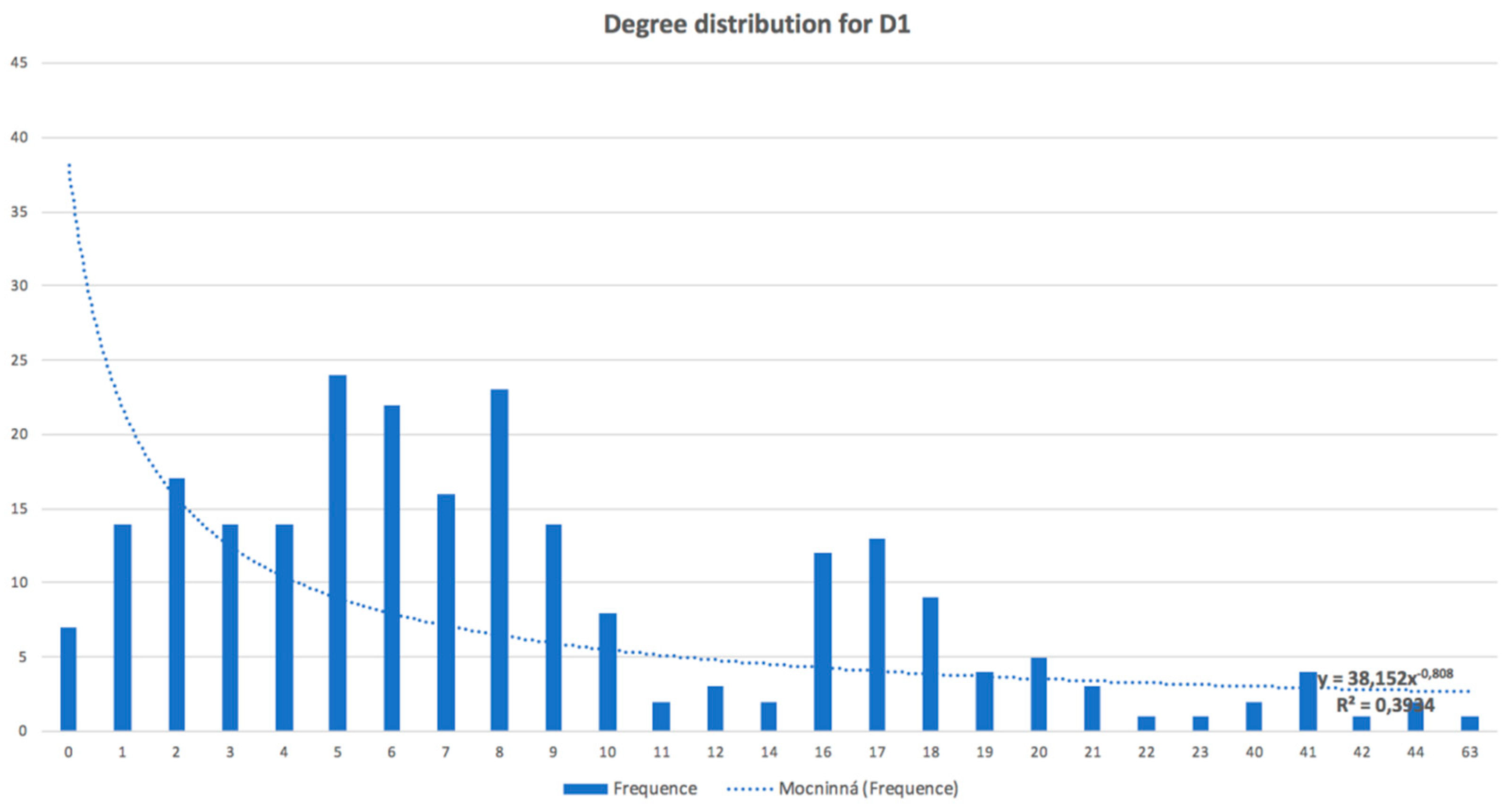
SilhouetteSilhouette of clusters is shown in Figure A1; pattern 1 is unstable, patterns 2, 3, and 4 are stable
Degree distributionDegree distribution is shown in Figure A2. The distribution does not show the power law.
Network diameter8
Network density0.04
Modularity0.604
11 communities found (algorithm [10]), modularity distribution visualized in Figure A3
Network diameter8
Clustering coefficient distributionAverage clustering coefficient (the mean value of individual clustering coefficients) of the network (algorithm [14] is used) is 0.582
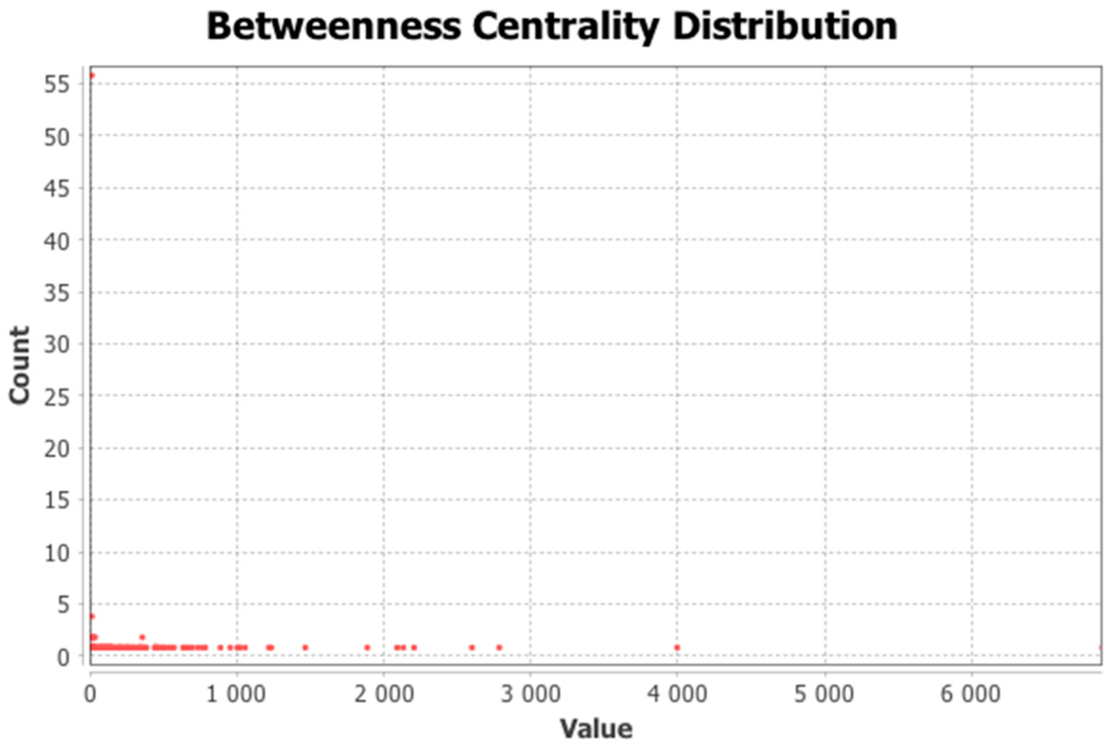
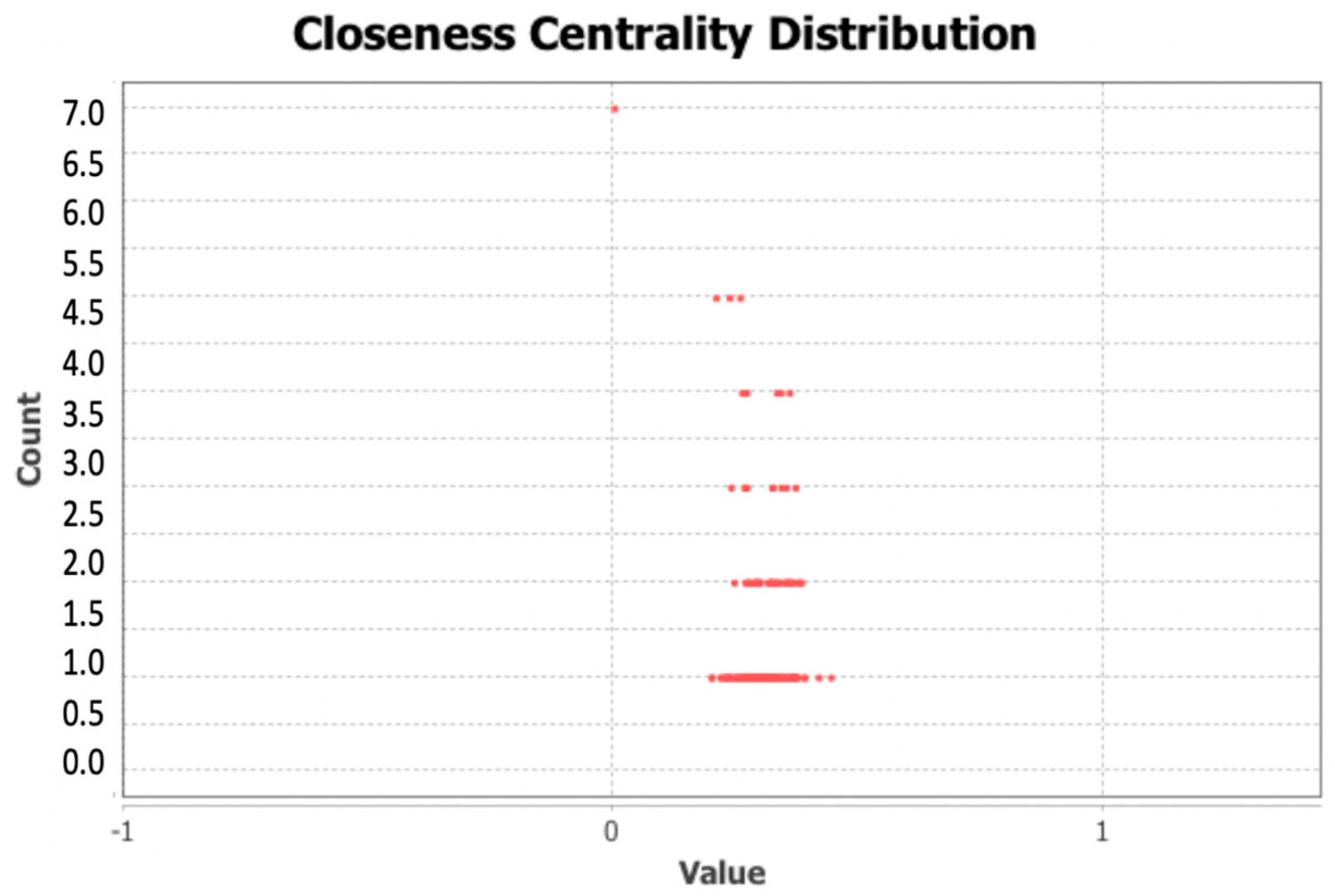
Distance centralitiesAverage path length: 3.38; Betweenness, Closeness, and Eccentricity distribution is shown in Figure A4, Figure A5 and Figure A6
Table 5. Outliers in metwork of D1.
PatternIdentified UserDescription/FoundingResult
5Central back-office userWe have 10 active users from central back-office, only one of them (user 10) is identified as an outlier—it could lead to detailed analysis.>
6SAP system userIt is found that this specific user participates in more roles, whereas all the other users from the given office participate in one role-specific only (could be inspected). The other users from this office are found within patterns 1, 2, and 3.OK
7Reporting, accountingTechnical user (12) runs automatic processing of invoices in specific states (e.g., after manual processing and batch processing from invoice management).OK
8IT deptVery special user (user 27) is an invoice creator. The user participates in many (2447) activities, mostly in role creator; the user is not a member of the central back-office. The user participates in eight roles, the most roles cumulated at one user. Only two users have eight roles; the second one (user 44) is identified in cluster 1—this user has only 297 activities. The number of roles could be inspected.OK
9Customer ServiceUser (29) from special Masterdata department participates in only one role (vendor maintenance). There is another user (180) from the same department participating in this role but processing fewer activities; this user (180) is identified in pattern 3.>
10Plant managerUser (36) from the customer service department participated in five activities on four invoices but with extremely long average time (3800). This should be checked.OK
11Customer ServicePlant manager (user 98) participates in only one invoice based on representation. It is not a case for the following inspection.OK
Table 6. Pattern representatives in D1.
FeaturePattern 1Pattern 2Pattern 3Pattern 4
Members75456942
Prevailed Order typeCall-offOrderCall-offOrder
Avg Count of orders60813112.410.2
Avg Count of roles3.92.61.71.4
Avg Max time1643511416438
Max time8976245722912667
Avg Min time3.312.845.886.2
Avg time11380.7158.9202.0
Table 7. Outliers in network of D2.
PatternIdentified UserDescription/FoundingResult
3Central back-office userUsers 82 and 38 are in this cluster.
User 83 is a user from back-office and is deactivated during the inspected time. The record cannot be compared.
User 38 is from the planning department, and as the only one from this department, is identified as an outlier. This should be analyzed, as the user could be inspected.
OK→1
6Central back-office userUser 6 is from central back-office and processed the highest number of activities (23,530) and invoices (18,766), twice more than the second highest number. Most of them are processed in one role.
This user is a regular outlier based on its behavior.
OK
7Warehouse keeperWarehouse keeper for two logistics warehouses is user 8. The user participates in six roles infrequently (only six users participate in six roles and one user in eight roles). This user differs from the other multi-roles by higher total time. Finally, the user is deactivated after the inspected period. All parameters lead to the suggestion that this user could be inspected.
8ReportingUser (44) from the reporting department participates in eight roles. There is only one other user (27 in the original dataset D1) participating in eight roles—it is identified and analyzed as an outlier. User 44 has a low average time.
The number of roles could be inspected.
9LogisticsUser (49) from logistics departments has low average time and all invoices are processed in the 2017 year (this limit is the difference—the reason is that user 49 is deactivated at the end of 2017).OK
10TechnicianTechnician user (75) has a high average time, only six activities processed for four invoices in 2017 year. Actually, the user is blocked. The user could be inspected.
11Customer ServiceUser (119) processed only nine activities for four invoices in the 2017 year. The user has a high average time and max time. The user could be inspected.
1 The sign → means that this user could be inspected.
Table 8. Pattern representatives in D2 (compared to source D1).
FeaturePattern 1 (D1)Pattern 1 (D2)Pattern 2 (D2)Pattern 3 (D2)Pattern 4 (D2)Pattern 5 (D2)
Members752017161475
Prevailed Order typeCall-offCall-offCall-offCall-offCall-offCall-off
Avg Count of orders60810873288193608
Avg Count of roles3.93.64.534.73.9
Avg Max time16433072121378113031643
Max time897689763362198940628976
Avg Min time3.31.52.23.12.83.3
Avg time1131807976,487,0113