Article

An Improved Blind Recognition Algorithm of Frame Parameters Based on Self-Correlation

College of Artificial Intelligence, National University of Defense Technology, Changsha 410073, China
*
Author to whom correspondence should be addressed.
Information 2019, 10(2), 64; https://doi.org/10.3390/info10020064
Submission received: 6 January 2019 / Revised: 14 February 2019 / Accepted: 14 February 2019 / Published: 16 February 2019
(This article belongs to the Section Information and Communications Technology)

Abstract

:
The blind recognition of the frame parameter plays a crucial role in frame synchronization in the background of a non-cooperation communication system. This paper proposes an algorithm based on self-correlation on the foundation of existed cumulative filtering algorithm. To overcome high BER, the peak-to-average ratio (PAR) is calculated to improve the algorithm. The simulation results proved that the performance of the algorithm has been improved.

1. Introduction

In digital communication systems, frame synchronization is a prerequisite for subsequent signal processing such as error correction and information extraction [1,2,3,4]. Frame synchronization words can mark the place for mapping receiving binary stream and eliminating redundant information. However, the manner of frame synchronization is different under different communication conditions. This paper focuses on the frame synchronization methods in the background of the non-cooperative communication. The frame parameters of the received binary signals must be blindly recognized in the context of non-cooperative communication. The cumulative filtering algorithm is the most commonly used blind identification method, the core of which is to use the randomness and synchronization features of asynchronous codes to identify the fame parameters by traversing frame lengths [5]. However, there are some disadvantages of this method, including weak resistance against bit errors, low correctness rate, too many memory matrix lines and also more consumption of the calculation resources. Based on the existed cumulative filtering algorithm, this paper proposes an improved frame parameter blind identification method based on self-correlation, and its performance is greatly improved.
The rest of the paper is arranged as follows: in Section 2, the cumulative filtering algorithm is briefly described. In Section 3, algorithm based on self-correlation is demonstrated detailly. In Section 4, the improved algorithm based on self-correlation is explored. Section 5 demonstrates the simulation results and Section 6 concludes the whole paper.

2. The Cumulative Filtering Algorithm

The signals are usually transmitted in the form of frames in the channel, through the location of which, it can achieve the synchronization between the receiver and the transmitter. The typical frame format can be seen in Figure 1. S represents the frame synchronization word, the length of which is M. D represents the data payload, the length of which is N. The length of a whole frame L = M + N. The transmitter packages the frame synchronization words and data payloads into the channel. At the receiver, the frame synchronization word S is repeated in cycles, while the data payload is random. The start of each frame can be found by detecting the location of the frame synchronization word S, and then subsequent operations can be performed.
In the background of non-cooperating communication, three key parameters: S, M, N are unknown parameters, which have to be recognized blindly [6].
Blind recognition of frame parameters can be achieved by using the periodicity of the frame synchronization sequence. Y is the received bit stream while X is a receiving matrix in the size of u × l, which are as shown in the Equation (1).
Y   =   [ y 1 y 2 y 3 ] [ y 1 y 2 y l y l + 1 y l + 2 y 2 l y ( u 1 ) l + 1 y ( u 1 ) l + 2 y u l ] = [ x 1 , 1 x 1 , 2 x 1 , l x 2 , 1 x 2 , 2 x 2 , l x u , 1 x u , 2 x u , l ] = X
When the number of matrix columns l is equal to the frame length, all elements of certain columns are either 0 or 1, while elements of other columns are randomly occurring as 0 or 1. The former ones are defined as synchronization columns, while others are defined as non-synchronization ones. The sum of each column is calculated, based on the results of which it can be recognized as a synchronization column when the result of a column is closed to 0 or u. Therefore, reasonable thresholds have to be elaborately designed [7,8].
δ u p and δ d o w n are the upper and lower threshold respectively. Equations (2) and (3) can be acquired according to reference [9] and 3 δ -criterion [10].
{ δ u p = ( u 2 + 6 × u 4 ) = 1 2 ( u + 6 u ) δ d o w n = ( u 2 6 × u 4 ) = 1 2 ( u 6 u )
u   >   36 θ 2
θ is a constant between 0 and 1. When θ equals 0.5, then:
u   >   144

3. Frame Parameters Recognition Algorithm Based on Self-Correlation

The frame synchronization code sequence has a local self-correlation function with sharp unimodal characteristics. Therefore, the frame synchronization parameters can be recognized by analyzing the self-correlation property. First, the mathematical model is analyzed and derived.
The signal transmitted s ( t ) can be calculated through the following equation:
s ( t )   = i = 0 N 1 c i g T ( t i T )
In Equation (5), g T represents signal generation filter while T represents symbol interval. The received signal r ( t ) can be calculated as:
r ( t ) = a   exp [ j θ ] s ( t τ ) + w ( t )
In Equation (6), a represents channel attenuation factor, θ represents the phase shift during transmission, τ represents the channel group delay, w ( t ) represents complex Gaussian white noise.
At the receiving end, the signal is determined by the ADC sampling to become a discrete time signal. The sampling interval is T s , and then T = T s N s ( N s is an integer). The sampling signal at the receiving end can be expressed as:
r ( n T s ) = a   e x p [ j θ ] i = 0 N 1 c i g ( n T s i T τ ) + w ( n )
Under cooperative communication conditions, maximum likelihood estimation is a common algorithm for the implementation of frame synchronization. The method uses a sliding time window to sample the signal and calculate a likelihood function between the sampled data and a known sequence of frame synchronization codes. The frame synchronization parameter is identified by searching for the maximum likelihood function value.
When the sliding window obtains the optimal delay estimate, its corresponding likelihood function takes the maximum value, which can be expressed as:
τ ^ = arg arg τ 0 Λ ( τ 0 , c )
Likelihood function can be expressed as:
Λ ( τ 0 , c ) = exp ( T 0 | r ( t ) a   exp [ j θ ] s ( t τ 0 ) | 2 d t N 0 )
In Equation (9), T 0 is the observation interval of the sliding time window. Equation (9) can be simplified as Equation (10) according to the reference [11].
Λ ( τ 0 , c ) = i = 0 N 1 exp ( 2 Re { ( a   exp ( j θ ) ) * y τ 0 i * c i * } N 0 )
After obtaining the logarithm of Equation (10), it can generate:
Λ ( τ 0 , c ) = i = 0 N 1 Re { ( a   exp ( j θ ) ) * y τ 0 i * c i * }
In Equations (10) and (11),   y τ 0 i represents discrete data sampled by the ADC. Using the known frame synchronization word sequence to perform cross-correlation calculation with the sampled data in the sliding window, Equation (11) can be equivalently simplified to:
Λ op ( τ m , c ) = 1 M | i = 0 M 1 y τ m i p i * | 2
In Equation (12), M represents the length of synchronization code sequence, p i represents the i th data in the sync code sequence while τ m indicates the starting moment of the sliding window.
In the context of non-cooperative communication, since the bits of synchronization word sequence are unknown, the cross-correlation calculation in Equation (12) cannot be directly used to recognize the frame synchronization word sequence. Therefore, the cross-correlation calculation in Equation (12) should be changed to the self-correlation calculation, which is shown in Equation (13).
Λ op ( τ m , τ n , c ) = 1 M | i = 0 M 1 y τ m i ( y τ n i ) * | 2
In Equation (13), y τ m i and y τ n i are the sampling data of different times in the sliding windows while the interval of the two sliding time windows are integer multiples of M.
In order to realize the synchronization word recognition in the non-cooperative communication background, the sampling data storage matrix Y is defined, and the multiplication results of the sampling data at corresponding positions of different moments in the sliding window are sequentially put into the storage matrix, as shown in Equation (14).
Y = [ y τ m 1 y τ n 1 y τ m 2 y τ n 2 y τ m n y τ n n ]
In Equation (14), n is the number of sampled signals in the sliding window
When n equals to the frame length or an integer multiple of the frame length, assuming that the received bit stream error rate is 0, the columns corresponding to the frame synchronization word should be all 0 or all 1. The data in other columns should be distributed randomly. When n is not the frame length or an integer multiple of the frame length, elements of each column in the storage matrix should be randomly distributed. Meanwhile, there is almost no case of all “0”s or all “1”s.
Considering the case of a data payload sequence, the probability that each element in the storage vector is 0 and 1 is:
{ P ( y i = 0 ) = 3 4 P ( y i = 1 ) = 1 4   ,   ( 1     i     n )
According to the knowledge of mathematical statistics [12], y i obeys the binomial distribution, and its mathematical expectation and variance are:
{ E ( y i ) = P ( y i = 1 ) = 1 4 D ( y i ) = P ( y i = 0 ) × P ( y i = 1 ) = 3 16
In the synchronization word sequence and the data payload sequence, the probability distributions of 0 or 1 are different. Therefore, in the case where the starting time and the length of sliding time window are constant, the presence of synchronization word sequence can be detected by calculating the distributions of 0 and 1 corresponding to each position in the sliding time window. After multiple iterations of the search, the final conclusion is reached. The sampling matrix Y * is defined as:
Y = [ y τ m 1 y τ n 1 y τ m 2 y τ n 2 y τ m n y τ n n y ( τ m + n ) 1 y ( τ n + n ) 1 y ( τ m + n ) 2 y ( τ n + n ) 2 y ( τ m + n ) n y ( τ n + n ) n y ( τ m + N n n ) 1 y ( τ n + N n n ) 1 y ( τ m + N n n ) 2 y ( τ n + N n n ) 2 y ( τ m + N n n ) n y ( τ n + N n n ) n ]
In Equation (17), N is the number of matrix rows. By summing the data in each column of Y * :
Y s u m = [ i = 0 N 1 y ( τ m + n i ) 1 y ( τ n + n i ) 1 i = 0 N 1 y ( τ m + n i ) 2 y ( τ n + n i ) 2 i = 0 N 1 y ( τ m + n i ) n y ( τ n + n i ) n ] = [ y 1 y 2 y n ]
In Equation (18), y i * obeys the binomial distribution with the parameter ( N ,   p ) , where p = 0.5.
Supposing that the random variable X n obeys the binomial distribution with the parameter ( n ,   p )   ( 0   <   p   <   1 ,   n     1 ) , when n is large enough, the binomial distribution has a normal distribution as its law of limit distribution according to the DeMoivre-Laplace central limit theorem. Thus, when the column y i * corresponds to the data payload sequence, taking a sufficient number of sliding window sample data, the probability distribution of y i * can be equivalent to that generated by obeying N ( N p ,   N p ( 1 p ) ) . When the column y i * corresponds synchronization word sequence, the probability distribution of y i * does not conform to the normal distribution characteristics, and y i * should be closed to N or 0 instead. The up and down decision threshold are δ u p and δ d o w n , Equation (19) can be achieved according to the 3 δ -criterion:
{ δ u p = u + 3 σ δ d o w n = u 3 σ
If y i * ( u 3 δ ,   u + 3 δ ) , the column represented by y i * is determined to correspond to the data payload sequence, otherwise it is determined to correspond to the synchronization word sequence.

4. Improved Frame Parameters Recognizing Algorithm Based on Self-Correlation

The algorithm described in the previous section uses the 3 δ criterion to determine the threshold during the decision phase. Actually, if the number of rows of the sampling matrix Y * is too low or the bit error rate (BER) is high, this decision method might lead to low accuracy. In this section, the peak-to-average ratio (PAR) and 3 δ -criterion are combined to search for the length of the frame. Afterwards, the frame length value obtained by the search is substituted into the self-correlation algorithm described in the previous section to obtain the synchronization word sequence. The definition of the PAR is as shown in Equation (20). Suppose array X contains n elements, then:
R = X max 1 n i = 0 n 1 X i
where R is PAR, X i ( 0     i     n ) is any element in array X . X max is the maximum value in the array.
While searching for the frame length value, it needs to first apply the upper limit value δ u p   =   u + 3 σ for coarse filtering and record the estimated frame length values and corresponding Y s u m * arrays. Afterwards, for the filtered Y s u m * arrays, it needs to calculate the peak-to-average ratio R of each array and determine the frame length corresponding to the array Y s u m * with the largest R value as a reasonable frame length estimate. It can be shown from the simulation results that the correctness of frame length recognition and error-resistance performance can be greatly improved by applying this kind of judgment method.
After obtaining the credible frame length estimation value, it is substituted into the algorithm in the previous section. When determining the 0 and 1, the up and down threshold are in the form of u ± α σ , where α is a constant slightly less than 3. Because the peak value is not as high as the ideal case when the bit error rate is high, if α takes 3, it will cause the problem of missing the “1”. However, the impact on the “0” decision is not obvious. The recommended value of α is 2.7.
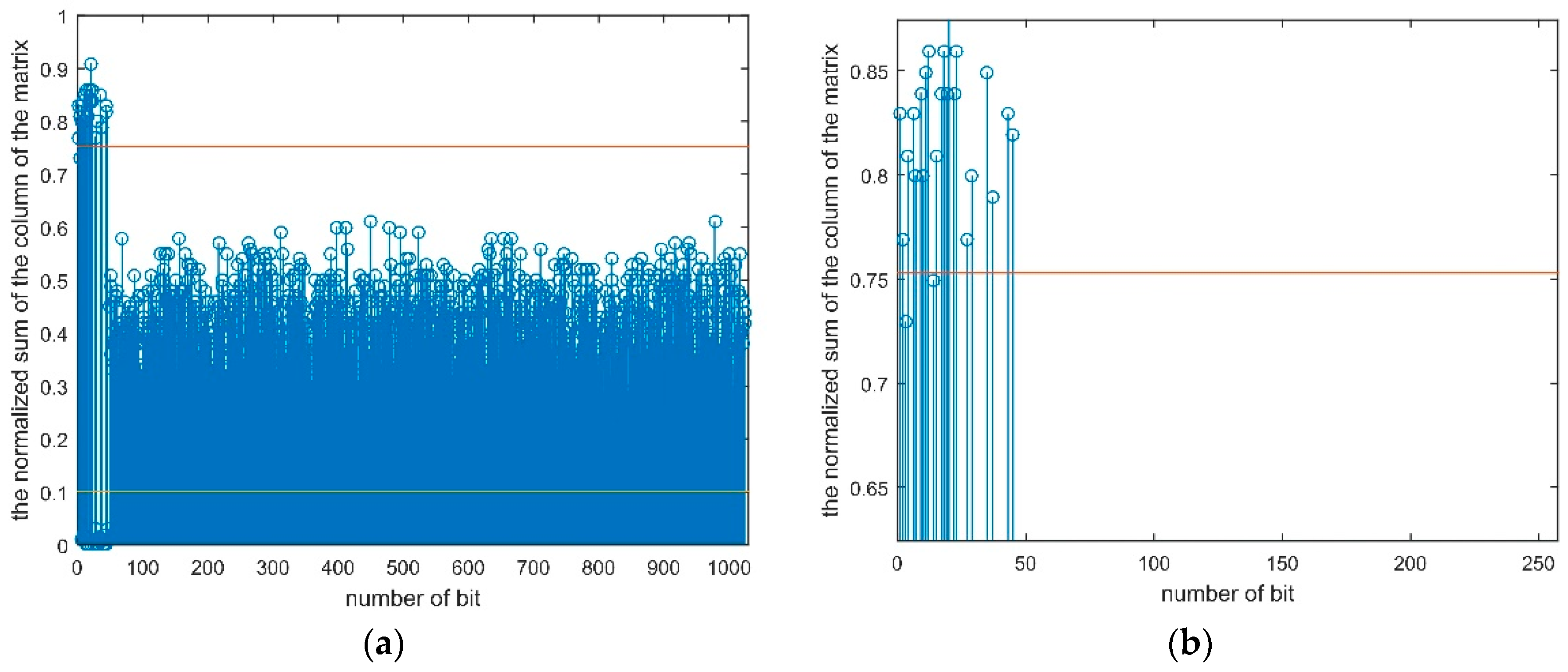
As is shown in Figure 2, the α of up and down thresholds are all 3. Figure 2a shows the result of Y s u m * when the frame length is correctly detected at bit error rate (BER) = 0.08. Figure 2b is the partial enlargement of Figure 2a at the frame header. There are two “1”s below the up threshold, which leads to the missing judgement. In Figure 3, α is 2.7, no missing judgement occurs when the receiving bit stream is unchanged, indicating that the fault tolerance is enhanced. It needs to be noticed that for Figure 2, Figure 3 and Figure 4, all the coordinates on y-axis have been normalized while x-axis represents bit numbers.

5. Simulation

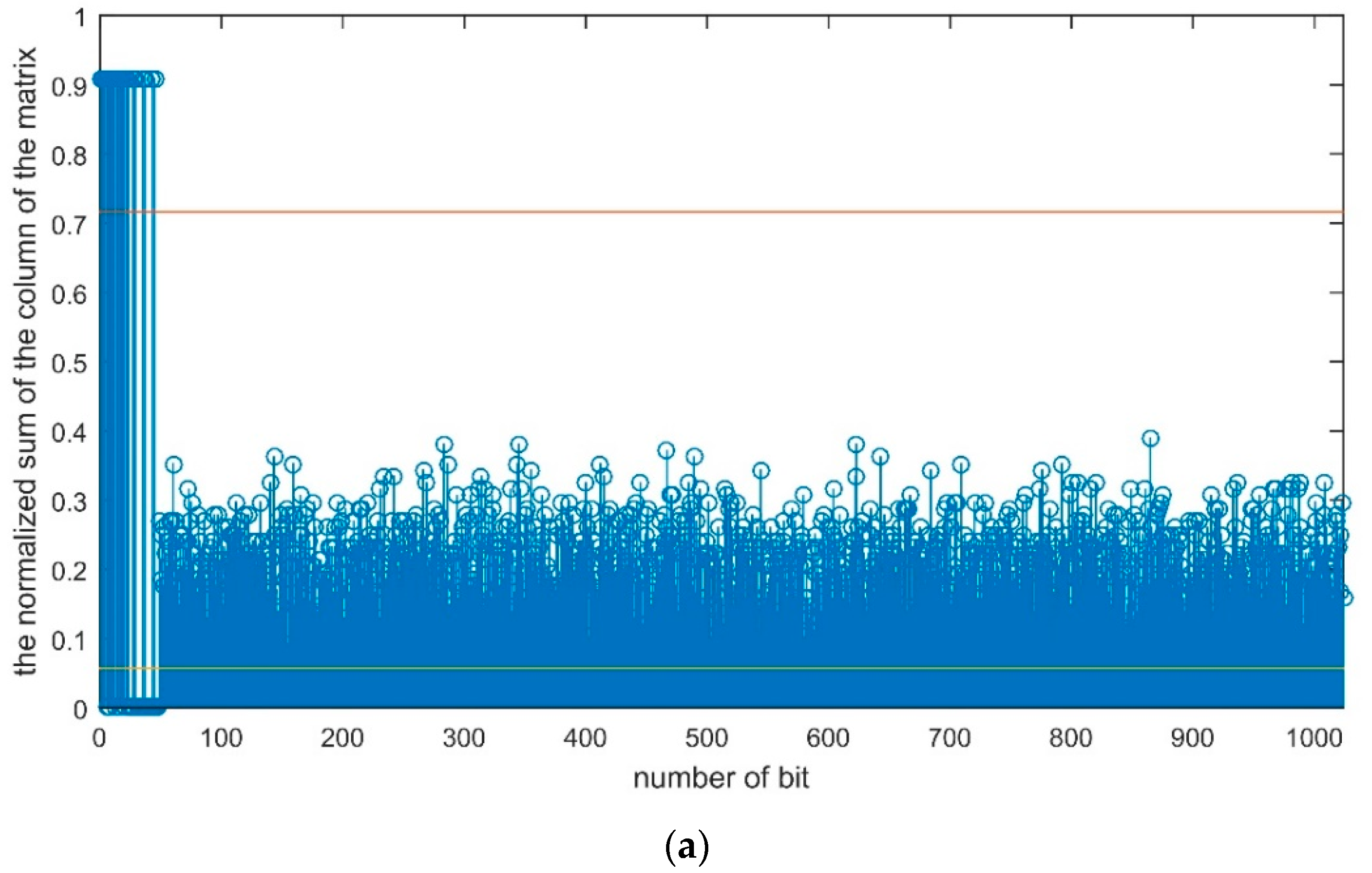
In the algorithm simulation experiments, the frame length is 1024 bits while the frame synchronization word sequence is 0xf628. The length of sliding window and frame initial values are 0 and 500 respectively. When the BER is 0, the result of the frame parameters recognition algorithm based on the self-correlation is shown in Figure 4. When the frame estimation is right, apparent self-correlation peaks appear at the head of the frame (Figure 4a). When the frame estimation has a fault, the sum of each column of the storage matrix Y s u m * is distributed randomly and there is no apparent peak (Figure 4b).
The two straight lines paralleling to the X-axis are the upper and lower threshold. From Figure 4a, the frame synchronization word can be recognized, which is 0xf628.
Assume that the bit stream is transmitted by QPSK system with BER [13]. The recognition accuracy rate is defined as the ratio of the times of recognizing correctly to the total times. 100 simulations are performed at each BER level. After 1000 algorithm simulations, the recognition accuracy rates of algorithms in Section 3 and Section 4 are demonstrated in Figure 5.
As the result shows, when the BER is over 0.03, the recognition accuracy rate of the unimproved algorithm is lower than 0.8, while that of the improved algorithm is 1. When the BER increases to 0.1, the unimproved algorithm can hardly recognize the frame parameters. However, the improved algorithm in Section 4 still works at the recognition accuracy rate of 0.43.

6. Conclusions

Based on the cumulative filtering algorithm, this paper proposes a frame parameters recognition algorithm based on self-correlation. In order to optimize the performance in the case of high BER, an improved frame parameters recognition algorithm based on self-correlation is proposed. The peak-to-average ratio (PAR) is introduced to estimate the reasonable frame length. Simulation results show that the performance of the algorithm is significantly improved, and this algorithm is of vital significance in practical engineering due to its reliability at high BER.

Author Contributions

Conceptualization, Y.X. and Y.Z.; software, Y.X.; supervision, Z.H.; validation, Y.Z.; writing (original draft), Y.X.; writing, review and editing, Y.X. and Y.Z.

Funding

This paper is supported by the Project supported by the National Nature Science Foundation of China (General Program), Grant No. 51575517.

Conflicts of Interest

The authors declare no conflict of interest.

References

  1. Cassaro, T.M.; Georghiades, C.N. Frame synchronization for systems over AWGN channels. IEEE Trans. Commun. 2004, 52, 484–489. [Google Scholar] [CrossRef]
  2. Lui, G.L.; Tan, H.H. Frame synchronization for Gaussian channels. IEEE Trans. Commun. 1987, 35, 818–829. [Google Scholar]
  3. Mostofa, M.; Howlader, K. Frame synchronization of convolutionally coded systems for packet transmission. IEEE Commun. Lett. 2001, 5, 307–309. [Google Scholar]
  4. Massey, J.L. Optimum Frame Synchronization. IEEE Trans. Commun. 1972, 20, 115–119. [Google Scholar] [CrossRef] [Green Version]
  5. Guo, K.F.; Meng, W. Research on Detection of Frame Head on Fixed Frame Length. J. Signal Inf. Process. 2014, 44, 33–36. [Google Scholar]
  6. Cluzeau, M.; Finiasz, M. Recovering a Code’s Length and Synchronization from a Noisy Intercepted Bitstream. In Proceedings of the IEEE International Symposium on Information Theory, Seoul, Korea, 28 June–3 July 2009. [Google Scholar]
  7. Imad, R.; Houcke, S. Theoretical Analysis of a MAP Based Blind Frame Synchronizer. IEEE Trans. Wireless Commun. 2009, 8, 5472–5476. [Google Scholar] [CrossRef]
  8. Qi, Y.; Wang, B.; Rong, M.; Liu, T. Comments on “Theoretical Analysis of a MAP Based Blind Frame Synchronizer”. IEEE Trans. Wireless Commun. 2011, 10, 3127–3132. [Google Scholar]
  9. Qin, J.Y.; Huang, Z.P. Novel Blind Recognition Algorithm of Frame Synchronization Words Based on Soft-Decision in Digital Communication Systems. PLoS ONE 2015, 10, e0132114. [Google Scholar] [CrossRef] [PubMed]
  10. Zhou, K. Early chatter detection in end milling based on multi-feature fusion and 3σ criterion. Int. J. Adv. Manuf. Technol 2017, 92, 4387–4397. [Google Scholar]
  11. You, X.Y.; Yang, P.; Peng, J.W. Frame synchronization and symbol timing synchronization based on soft decision feedback in burst communication. Comput. Eng. Appl. 2018, 54, 96–100. [Google Scholar]
  12. Sheldon, M.R. A First Course in Probability, 8th ed.; China Machine Press: Beijing, China, 2014; pp. 127–134. [Google Scholar]
  13. Hamaguchi, K.; Shoji, Y.; Ogawa, H. BER performance of coherent-QPSK transmissions affected by phase noise from frequency converters. In Proceedings of the 54th IEEE Vehicular Technology Conference, Atlantic, NJ, USA, 7–11 October 2001. [Google Scholar]
Figure 1. Frame sequence structure diagram.
Information 10 00064 g001
Figure 2. (a) This is the figure of Y s u m * with BER = 0.08, α = 3. (b) This is the partial enlargement of Figure 2a at the frame header. There are two “1”s below the up threshold, causing the missing judgement.
Information 10 00064 g002
Figure 3. (a) This is the figure of Y s u m * with BER = 0.08, α = 2.7. (b) This is the partial enlargement of Figure 3a at the frame header. There are no “1”s below the up threshold, indicating that all ”1”s are determined correctly.
Information 10 00064 g003
Figure 4. This is the result of Y s u m * when BER is 0. (a) The peak appears when the frame estimation is right. (b) No peak appears when the frame estimation is fault.
Information 10 00064 g004aInformation 10 00064 g004b
Figure 5. Comparation of the improved and unimproved algorithm. Obviously, the improved algorithm performs better under high BER circumstances.
Information 10 00064 g005