Article

Design and Comparative Study of Advanced Adaptive Control Schemes for Position Control of Electronic Throttle Valve

by
Amjad J. Humaidi
1,* and
Akram H. Hameed
2
1
Department of Control and System Engineering, University of Technology, Baghdad 10066, Iraq
2
Baghdad State Company of Electricity Distribution, Al-Sader Branch, Ministry of Electricity, Baghdad 10059, Iraq
*
Author to whom correspondence should be addressed.
Information 2019, 10(2), 65; https://doi.org/10.3390/info10020065
Submission received: 20 January 2019 / Revised: 12 February 2019 / Accepted: 13 February 2019 / Published: 16 February 2019

Abstract

:
This paper investigates the performance of two different adaptive control schemes for controlling the angular position of an electronic throttle (ET) plate. The adaptive backstepping controller and adaptive sliding mode backstepping controller are the controllers under consideration. The control design based on these adaptive controllers is firstly addressed and the stability analysis of each controller has been presented and the convergence of both position and estimation errors for both controllers have been proved. A comparison study of the performance of both controllers has been conducted in terms of system transient characteristics and the behavior of their associated adaptive gain. The simulation has been implemented within the environment of the MATLAB package.

1. Introduction

Internal combustion engines require the regulation of airflow to control engine output speed, output torque, spark timing and the air-fuel ratio. Until the end 1980s, the driver was in direct control of engine speed and power. The throttle valve was controlled by a wire connected directly to the accelerator pedal. The cruise control systems have also the technology of controlling the speed of the engine by connecting the throttle body by a wire, which is controlled with vacuum or electronic motor. The electronic throttle control (ECT) system driven by wire technology has appeared in 1998. The series-7 of BMW-manufactured cars was the first series, which involved with the technology of electronic throttle body (ETB). However, recent advances in control and technology have enabled the throttle valve to be operated by electric actuators and control systems. Vehicle production companies are interested in developing electronic control systems for the throttle body. Replacing the cable with an electronic system would increase the response time and improve the overall performance of the throttle [1,2].
The electronic throttle control (ETC) system is one beneficial technology that replaces drive-by-wire technology and it has emerged in the automotive industry due to the increased regulations in terms of emission control, fuel consumption, drivability and safety [1,2]. The system consists of a throttle plate attached with a preloaded spring and driven by an electronic-controlled dc motor such as to regulate the intake airflow. For minimizing emissions and maximizing fuel economy in modern vehicles, an optimal air-fuel mixture in the combustion chambers is achieved using the engine control unit, which maps and computes the angle of the throttle plate to many entries such as engine speed, accelerator pedal position, cruise control command, and so forth. The ETC system has to respond to the prescribed reference from the engine control unit with fast transient and precise control to regulate the angular position of the throttle plate [3,4].
As shown in Figure 1, the electronic throttle valve consists of a DC motor, driven by a driver, a motor pinion gear, an intermediate gear, a sector gear, a valve plate, a nonlinear spring and position sensor.
A backstepping control algorithm is a powerful procedural control strategy. It is established according to iterative steps which end when the control action reaches the channel of desired state. Throughout the design procedure of the backstepping control algorithm, virtual controllers are assigned to intermediate state variables [5]. However, the design of this procedural algorithm requires a prior knowledge of both systems’ uncertainty and parameters. As such, the concept of convergence in the presence of uncertainty, like an exertion of disturbance, will be different from that in the case of no uncertainty. Adaptive backstepping control (ABSC) is an extended version of a backstepping control strategy. The certainty equivalence adaptive control is one of several recent adaptive strategies based on adaptive law, which works to estimate the unknown parameters to represent the real value of the unknown ones. The combination of adaptive law based on Lyapunov stability analysis with backstepping control strategy yields almost the same performance characteristics as that resulting from a non-adaptive backstepping controller with robustness capability [6].
Sliding mode control (SMC) is a discontinuous control strategy, which is designed based on variable structure synthesis. The milestone in designing SMC is the existence of sliding surface. Whenever the trajectory of error state is enforced to reach this sliding surface, it asymptotically slides to an equilibrium point. The SMC has good robust characteristics against uncertainty in its system parameters and also resists external disturbance with its bounded matched property [7]. However, the necessity of knowing the upper bound of uncertainty and the nominal values for the uncertain parameters has imposed restrictions to the robustness against uncertainty in parameters.The robustness capabilities may be altered when dealing with a totally unknown disturbance level. The integration of SMC strategy with adaptive control theories lead to the emergence of what is called “Adaptive Sliding Mode Control (ASMC)”. This combination provides the SMC with the powerful features given by both methodologies, i.e., the robustness characteristics gained by SMC together with the adaptive capability acquired by adaptive control theory to cope with totally unknown parameters [8,9]. Furthermore, combining the features of adaptive sliding mode control with backstepping control acquires the benefits of performance characteristics and robustness of the three strategies and yields so called Adaptive sliding mode backstepping control (ASMBC).
In the present work, the performance of two adaptive controllers named the adaptive backstepping controller and Adaptive sliding mode backstepping controller are investigated for plate angular position control of electronic throttle valve system.
The work of the paper has been motivated by the recent researches in nonlinear and robust adaptive control theories presented by (Humaidi and Hameed 2017–2018) [9,10,11].
In what follows, some recent relevant control methodologies for throttle valve are briefly discussed. Chen et al. (2012) proposed an adaptive fuzzy logic based sliding mode controller to enhance the control strategy robustness with respect to parameter variations and external disturbances for electronic throttle [12]. Caruntu et al. (2012) has adopted Smith-predictor control, which is used to control the electronic throttle body. There have been experiments conducted to implement the control strategy of throttle valve over a delayed-driven network [13]. Xinghua et al. (2017) presented a stabilizing controller based on stochastic dynamic systems. The stability concept is analyzed in terms of probability and the proof of stability is established by a control design based on sliding mode technique. The proposed control design is applied to automotive throttle valve and it is verified using experimental data [14]. Kurihara and Yamaguchi (2017) designed a back-stepping control to improve the dynamic response and resolution of electronic control throttle valve system in the presence of nonlinearities such as static friction and backlash of gear train. The stability of backstepping controlled systems has been proved and the simulated results of two steps backstepping algorithm showed that this advanced control strategy outperforms a conventional PID controller in terms of resolution and transient characteristics [15]. Jiao et al. (2018) designed and implemented an adaptive finite time servo control strategy for real electronic throttle valve systems. This work has presented an integrated framework of the adaptive backstepping algorithm based on the stability theory of finite convergence time to guarantee the trajectory tracking of throttle valve opening [16]. Rui et al. (2018) presented a nonlinear backstepping tracking control strategy, taking into account the unknown external disturbances and input saturation. Throughout the control design, an auxiliary design system is included to overcome the input saturation and sliding mode control is used to compensate for the unknown external disturbance. The desired tracking performance based on nonlinear controller is verified based on simulated results [17]. Nia and Nagamune (2018) suggested a switching gain-scheduled PID control strategy. The design of controller consists of multiple gain scheduled PID controllers, which are instantaneously switched to appropriate regions defined for battery voltage and varying velocity of throttle valve. The experimental results showed that this control strategy has better reference tracking performance than classical controllers for different scenarios [18]. Yang et al. (2018) proposed a new novel nonlinear controller for electronic throttle valve systems with an unknown state and disturbance level. The controller is based on using a Leunberger-sliding mode observer to estimate the throttle vale opening change and utilized fuzzy logic control to approximate the total uncertainty. The stability and convergence of a controlled system has been proved based on Lyapunov method and the effectiveness of proposed nonlinear controller is verified, via numerical simulation, in terms of transient characteristics, precision and robustness [19]. Eski and Yildirim (2017) made a performance comparison among four controllers such as PID controller, model-based neural network controller, adaptive neural network-based fuzzy inference controller and robust adaptive neural-based fuzzy inference controller in terms of transient characteristics of position-controlled electronic throttle valve system. The simulated results showed that robust adaptive neural-based fuzzy inference controller outperforms the other suggested controllers [20]. Wang et al. (2016) proposed a robust adaptive scheme for position control of electronic throttle (ET) valve. Design of robust adaptive sliding mode (RASM) control scheme has been developed to adapt, estimate and compensate nonlinearities due to gear backlash, return-spring limp frictions and parameter uncertainties. A satisfactory dynamic performance has been presented by RASM controller for position control of ET system [21]. In reference [22], Xiao-Jian Li and Guang-Hong Yang focused on the adaptive decentralized control problem for a class of interconnected nonlinear systems, where the interconnections are assumed to be unknown and completely nonlinear. The adaptive law is established by introducing a smooth switching function. The stability of closed-loop system based on adaptive decentralized controller is analyzed using graph theory and Lyapunov method. The work proved that all states of closed-loop system are globally bounded and the tracking errors converges to a compact set.
One of the problems in adaptive control schemes is the bound availability of disturbance. This problem has been addressed in the present work. In an adaptive backstepping algorithm, the bound of disturbance is a prerequisite for the adaptive controller to work properly and estimate the disturbance. On the other hand, the adaptive backstepping sliding mode controller works to estimate this bound and therefore the problem of disturbance bound has been solved or avoided with this controller.
In the present work, the main contribution is to design two adaptive nonlinear controllers for angular position control of the throttle plate to satisfy the following objectives:
  • To robustly control the position of the throttle plate of the throttle valve using adaptive backstepping control and adaptive sliding mode backstepping control.
  • To robustly control the position of the throttle plate of the throttle valve.
  • To cope the unknown (upper bounded) exerted disturbance based on adaptive backstepping control, where disturbance upper bound is needed.
  • To cope the unknown upper bound of exerted disturbance using adaptive sliding mode backstepping control, where disturbance upper bound is estimated.
Moreover, throughout the application of both controllers, the constrained control effort represented by the supplied battery has been considered, which is a limitation avoided by almost all the aforementioned researchers.
The whole paper comes with five sections: Section 2 presents the dynamic modeling of the throttle valve, Section 3 focuses on the controller design and proof of error convergence based on Lyapunov stability analysis, Section 4 discusses the computer simulation results and finally Section 5 highlights the main concluded points due to applications of two adaptive control strategies.

2. Mathematical Model

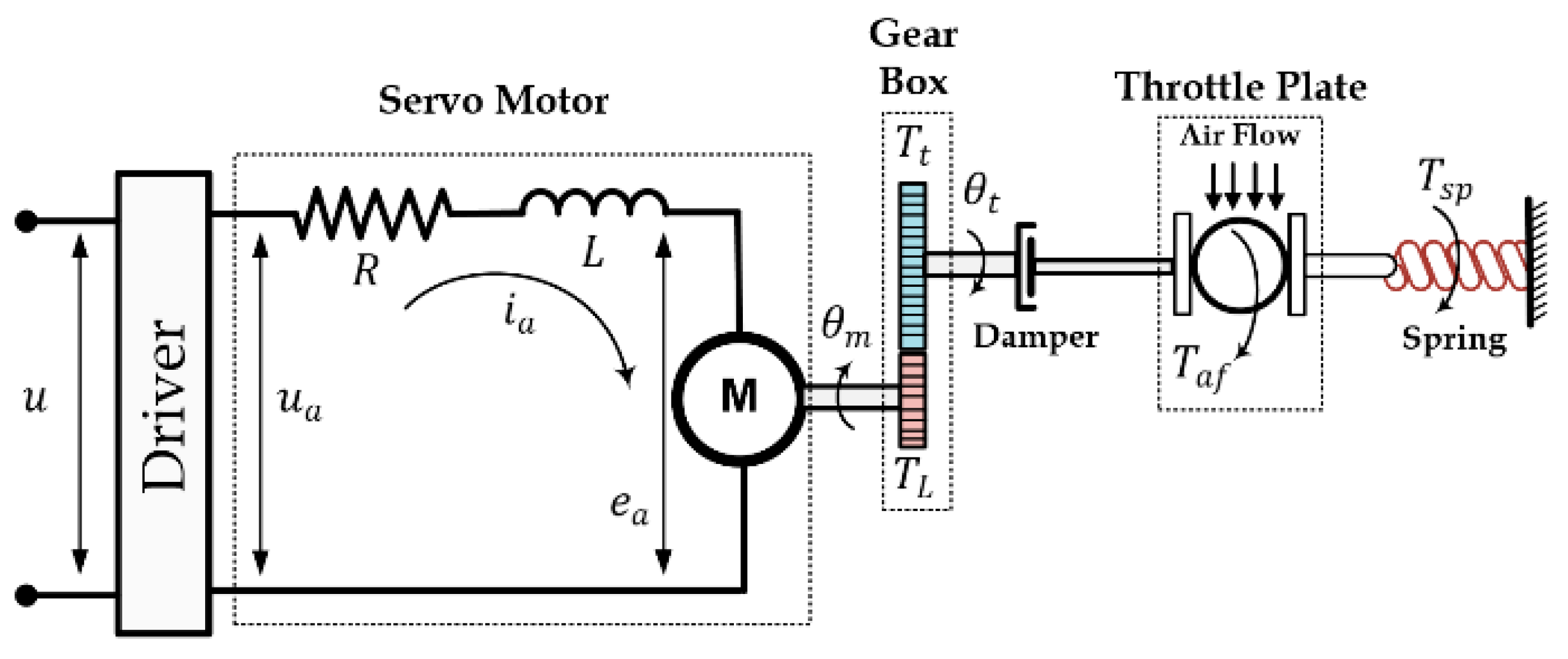
The detailed schematic diagram of throttle valve system is illustrated in Figure 2.
Applying Kirchhoff’s voltage law around armature circuit, one can get the equation
u a = K d   u = R   i a + L   d i a / d t + e a
where, R is the armature resistance, L is armature inductance, K d is the drive gain, u a is applied voltage, i a is the current passing through the motor winding, e a is the back e.m.f voltage which is expressed by
e a = K b   d θ m / d t
where, K b is the back e.m.f constant and θ m is the shaft angular position of motor. Using Equation (1), one can have
K d   u = R   i a + L   d i a / d t + K b   d θ m / d t
It has been shown that the coil inductance L has no effect on the dynamic response and it can be neglected [1,12]. As such Equation (3) can be written as;
i a = ( K d / R )   u ( K b / R )   d θ m / d t
The developed torque of DC motor is given as
T m = K t   i a
where, K t is motor torque constant. The generated torque is used to compensate the motor shaft motion, the load torque T L , viscosity and friction damping:
T m = J m d 2   θ m / d t 2 + B m d θ m / d t + B m o + T L
where, B m and B m o denotes the viscosity damping and static friction coefficients of motor shaft, respectively, J m is the motor shaft inertia.
On the other part of gear, the transmitted toque T t tries to overcome the throttle plate motion, spring torque, viscosity damping and static friction of throttle valve;
T t = J t d 2 θ t / d t 2 + B t d θ t / d t + B t o + T s p + T a f
where, B t and B t o represents the viscosity damping and static friction coefficients of the throttle, respectively, T a f is the torque due to airflow, J t is the throttle inertia and T s p is the return spring torque defined by [23]
T s p = K s p   ( θ t + θ t o )
where, K s p is the elastic coefficient of the spring, θ t o is throttle angle of throttle plate.
Using the gear ratio N = θ m / θ t = T t / T L , Equations (3)–(7) can be combined to give
d 2 θ t / d t 2 = a 1 θ a 2   d θ / d t + b 1 u f 1 f 2 f 3
The airflow torque T a f which has no significant effect on the behavior of electronic throttle and hence it can be treated as unknown external disturbance.
If one set x 1 = θ , x 2 = θ ˙ and y = x 1 , then the state variable representation can be written as
x ˙ 1 = x 2 x ˙ 2 = a 1 x 1 a 2 x 2 + b 1   u + w
where,
a 1 = K s p / ( J m   N 2 + J t ) ,   b 1 = N K t   K d / ( R   ( J m   N 2 + J t ) ) , a 2 = [ ( N 2   K b   K t + R   ( B m   N 2 + B t ) ) / ( R   ( J m   N 2 + J t ) ) ] ,   w = f 1 f 2 f 3 , f 3 = ( N B m o + B t o )   / ( J m   N 2 + J t )   ,   f 2 = T a f   / ( J m   N 2 + J t ) ,   f 1 = K s p   θ 0 / ( J m   N 2 + J t )
In matrix form Equation (9) becomes
[ x ˙ 1 x ˙ 2 ] = [ 0 1 a 1 a 2 ] [ x 1 x 2 ] + [ 0 b 1 ] u + [ 0 w ] y = [ 1 0 ] [ x 1 x 2 ]

3. Controller Design and Stability Analysis

3.1. Backstepping Control

If it is assumed that the uncertainty w is known, the following analysis is followed. Let z 1 represents the error between the actual state x 1 and the desired trajectory x d described by [5]:
z 1 = x 1 x d
The time derivative of above equation gives
z ˙ 1 = x ˙ 1 x ˙ d or , z ˙ 1 = x 2 x ˙ d
Defining the error z 2 as follows;
z 2 = x 2 α
Equations (12) and (13) gives
z ˙ 1 = α + z 2 x ˙ d
Using,
α = c 1 z 1 + x ˙ d
Equation (4) becomes
z ˙ 1 = c 1 z 1 + z 2
Taking the time derivative of Equation (13) gives
z ˙ 2 = x ˙ 2 α ˙ or , z ˙ 2 = a 1 x 1 a 2 x 2 + b   u + w α ˙
The control action can be chosen as
u = 1 b   ( a 1 x 1 + a 2 x 2 w + α ˙ c 2 z 2 z 1 )
Substituting Equation (18) into Equation (17) to obtain
z ˙ 2 = c 2 z 2 z 1
Using Equation (15), one can obtain the expression for α ˙ ,
α ˙ = c 1 x 2 + c 1   x ˙ d + x ¨ d
and substituting it into Equation (18), the control law becomes
u = 1 b ( ( a 1 c 1 c 2 1 )   x 1 ( a 2 + c 1 + c 2 )   x 2 + ( c 1 c 2 + 1 )   x d + ( c 1 + c 2 )   x ˙ d + x ¨ d w )
To investigate the stability, the following Lyapunov candidate is chosen
V ( z 1 , z 2 ) = z 1 2 / 2 + z 2 2 / 2
The derivative of Lyapunov function gives
V ˙ ( z 1 , z 2 ) = z 1 z ˙ 1 + z 2 z ˙ 2 or , V ˙ ( z 1 , z 2 ) = z 1 2 z 2 2 0
Therefore, one can conclude that the control law described by Equation (21) leads to an asymptotically stable system.

3.2. Adaptive Backstepping Control

If the uncertainty w is assumed to be bounded and unknown, then by employing the certainty equivalence principle the actual value of uncertainty w is replaced by its estimate w ^ and the difference between them is defined as the estimation error w ˜ = w w ^ . Therefore, the control law is based on uncertainty estimate rather than the actual value [6], i.e.,
u = 1 b   ( a 1 x 1 a 2 x 2 w ^ + α ˙ c 2 z 2 + z 1 )
Then, Equation (19) becomes
z ˙ 2 = c 2   z 2 z 1 + w ˜
To develop the adaptive law, the following Lyapunov function is selected;
V ( z 1 , z 2 , w ˜ ) = z 1 2 / 2 + z 2 2 / 2 + w ˜ 2 / 2 β
The time derivative of candidate Lyapunov function can be given as
V ˙ ( z 1 , z 2 , w ˜ ) = z 1 2 z 2 2 + w ˜   z 2 w ˜ w ^ ˙ / β or , V ˙ ( z 1 , z 2 , w ˜ ) = = z 1 2 z 2 2 + w ˜   ( z 2 w ^ ˙ / β )
To enforce the above equation to be negative definite, then the following adaptive law is deduced
w ^ ˙ = β z 2 or , w ^ ˙ = β   ( x 2 + c 1 x 1 c 1   x d x ˙ d )
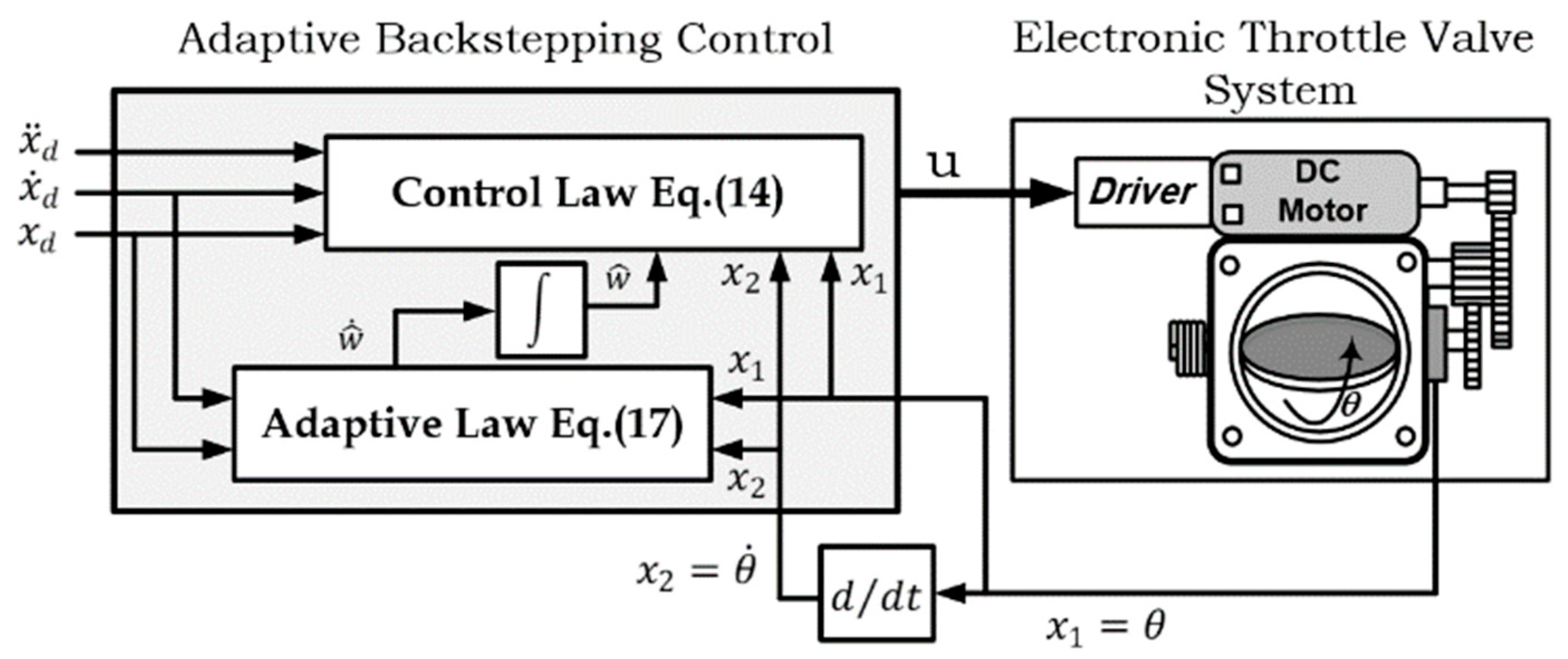
The adaptive backstepping control scheme for electronic throttle valve system is sketched in Figure 3.

3.3. Adaptive Sliding Mode Backstepping Control

Considering the error equations of Equations (11)–(17) the sliding surface can be written as [24]:
s = c   z 1 + z 2
where c > 0 is a constant. Equation (28) can be rewritten as:
z 2 = s c   z 1
Taking the derivative of Equation (28), one can have
s ˙ = c   z ˙ 1 + z ˙ 2 or s ˙ = c ( c 1 z 1 + z 2 ) a 1 x 1 a 2 x 2 + b   u + w α ˙
The disturbance term is revisited here as | w | λ > 0 which means the disturbance is bounded and to make the scenario more conflictive, the disturbance bound is assumed to be unknown. Hence the adaptive sliding mode backstepping is presented also based on certainty equivalence where an estimate of the disturbance bound is used λ ^ .
The candidate Lyapunov function is constructed as:
V ( z 1 , s , λ ^ ) = z 1 2 / 2 + s 2 / 2 + λ ˜ 2 / 2 γ
where, λ ˜ = λ λ ^ and λ ˜ ˙ = λ ^ ˙ . The time derivative of the Lyapunov candidate is:
V ˙ ( z 1 , s ,   λ ^ ) = z 1 z ˙ 1 + s s ˙ λ ˜ λ ^ ˙ /   γ
Equation (31) can be written as,
V ˙ ( z 1 , s , λ ^ ) = z 1 ( c 1 z 1 + z 2 ) + s ( c ( c 1 z 1 + z 2 )   a 1 x 1 a 2 x 2 + b   u + w α ˙ ) λ ˜ λ ^ ˙ /   γ
Based on sliding mode theory, the control action is selected to be composed of two parts as follows:
u = u n + u a s m
where u n is the performance part which is given by;
u n = ( c ( c 1 z 1 + z 2 ) + a 1 x 1 + a 2 x 2 + α ˙ z 1 h s ) / b
where h > 0 is a design parameter, and the robustness part which is given by
u a s m = λ ^ s g n ( s ) / b
Substituting the control parts u n and u a s m into Equation (33) leads to the following expression:
V ˙ ( z 1 , s , λ ^ ) = z 1 ( c 1 z 1 + z 2 )   + c ( c ( c 1 z 1 + z 2 ) a 1 x 1 a 2 x 2 c ( c 1 z 1 + z 2 ) + a 1 x 1 + a 2 x 2   + α . x 1 h s + w α . λ ^ s g n ( s ) )
Equation (36) can be rewritten as
V ˙ ( z 1 , s , λ ^ ) = c 1 z 1 2 + z 1 z 2 z 1 s h s 2 + w   s λ ^ s s g n ( s ) λ ˜ λ ^ ˙ /   γ
From the fundamentals of linear algebra, the fact of | w . s | | w | . | s | λ | s | and s . s g n ( s ) = | s | can be utilized such that Equation (37) becomes
V ˙ ( z 1 , s , λ ^ ) c 1 z 1 2 + z 1 ( s c z 1 ) z 1 s h s 2 + λ | s | λ ^ | s | λ ˜ λ ^ ˙ /   γ or , V ˙ ( z 1 , s , λ ^ ) c 1 z 1 2 c z 1 2 h s 2 + λ ˜ ( λ | s | λ ^ ˙ /   γ )
The time derivative of Lyapunov function can be forced to be negative definite by choosing the following adaptive law;
λ ^ ˙ = γ | s |
Equation (38) becomes,
V ˙ ( z 1 , s , λ ^ ) c 1 z 1 2 c z 1 2 h s 2 0
This makes z 1 converges asymptotically to zero, which means that the state x 1 asymptotically tracks the desired trajectory   x d .
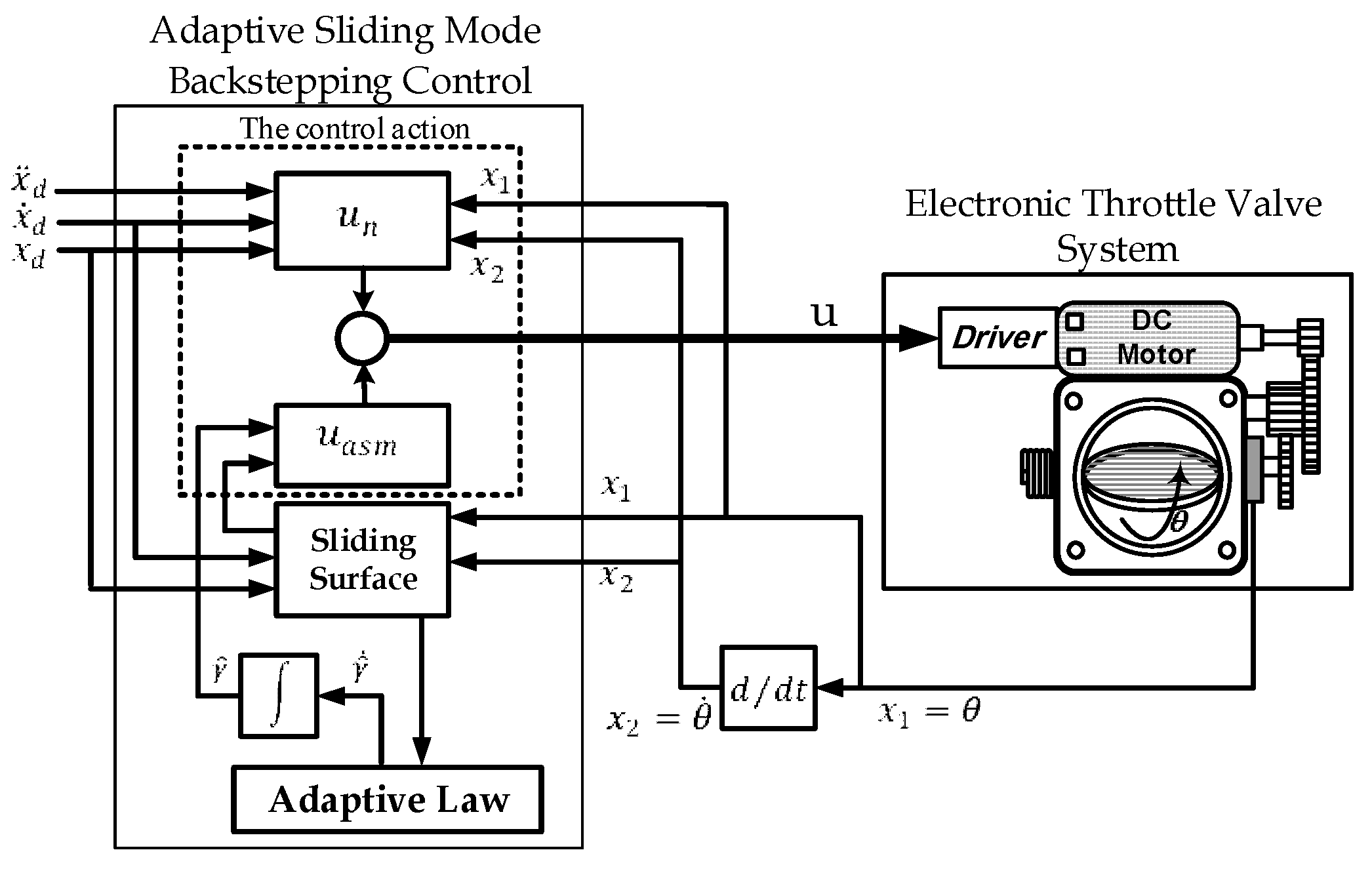
The schematic diagram of adaptive sliding mode backstepping controlled throttle valve system is illustrated in Figure 4.

4. Computer Simulation

The Throttle valve model has been implemented for simulation using MATLAB/SIMULINK. The throttle valve parameters are listed in Table 1 [12].
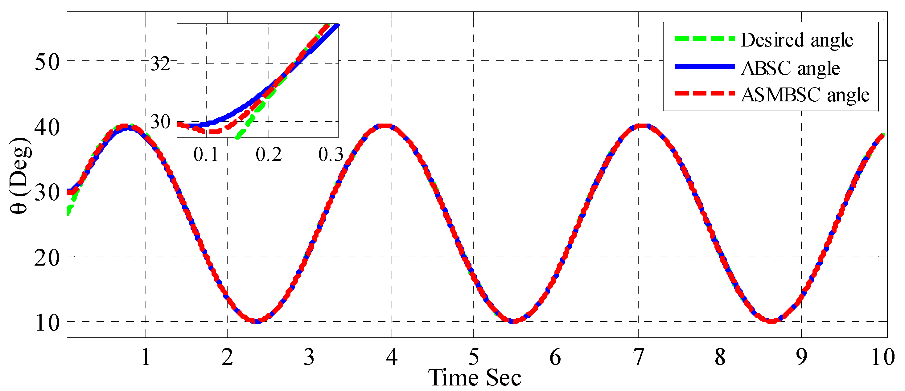
Simulation is based on sinusoidal desired trajectory represents an acceleration demand above the engine idle. The sinusoidal desired trajectory oscillates at frequency of 0.5 rad/s and swings within the angular limit (10°–40°). Also, the sinusoidal desired trajectory starts with an initial condition of 25°, while the actual throttle plate angle is initiated with angle 30°. The design parameters for the adaptive backstepping and adaptive backstepping sliding mode control were tuned based on try-and-error procedure. The selection of design parameter set is made according to the best performance and convergence rate. Therefore, the following design parameters have been obtained: c 1 = 200 , c 2 = 20 , β = 15 , c = 3 , h = 20 , γ = 0.7 .
The disturbance T a f is simulated by a sinusoidal air flow with height of 0.2 N and frequency of 4 rad/s. The DC motor is energized by 24 Volt battery such that the maximum allowable control action ranges between (0–24) which a limitation avoided by most of the researchers.
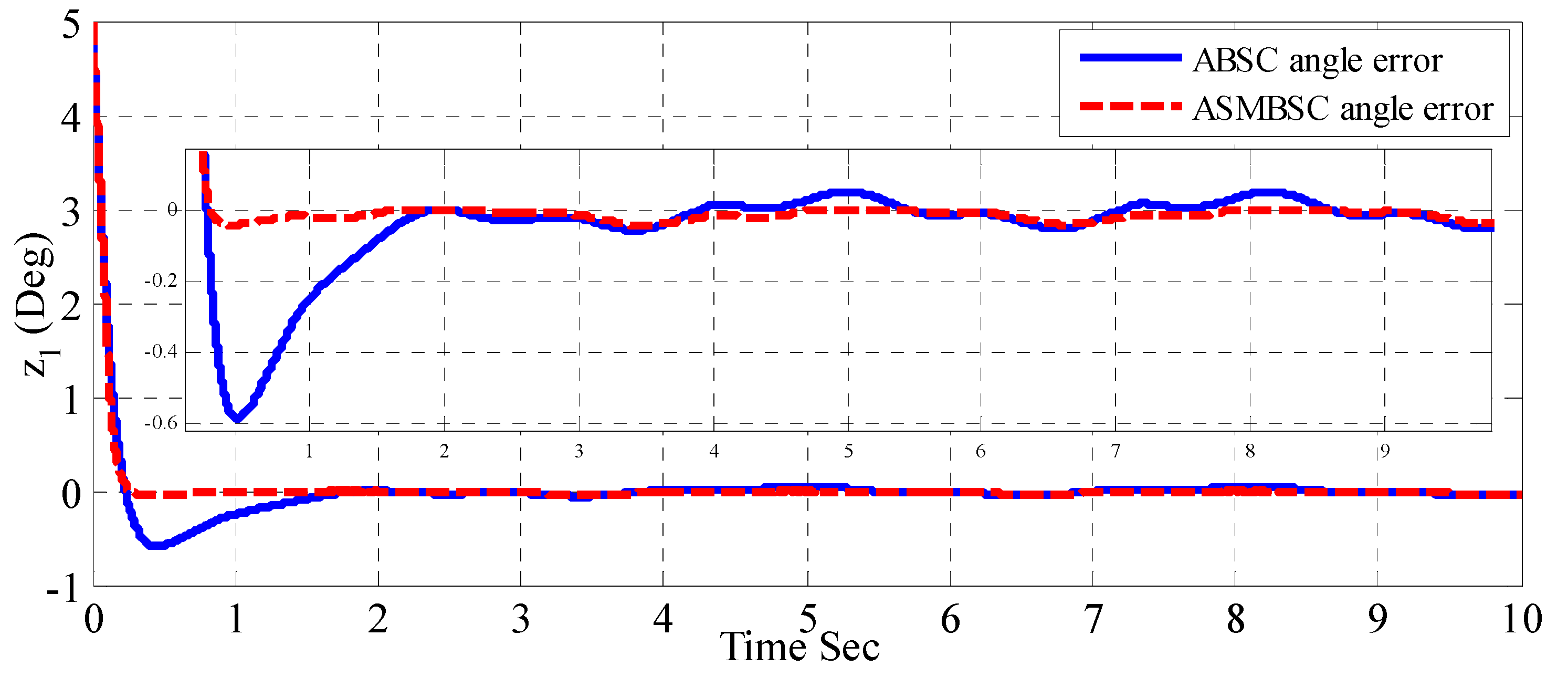
Figure 5 shows the throttle plate angle responses for both adaptive backstepping and adaptive sliding mode backstepping controller. The figure shows that the adaptive sliding mode control gives better transient response and robust characteristics as compared to an adaptive backstepping controller. Figure 6 shows the error response resulting from both adaptive control schemes. The performance of controller in terms of error is evaluated by measuring root mean square of error (RMSE) over entire simulation run. The best controller is the one which gives less RMSE. Based on the simulation shown in Figure 6, it can be seen that the adaptive sliding mode backstepping controller gives less RMSE compared to an adaptive backstepping controller, as indicated in Table 2.
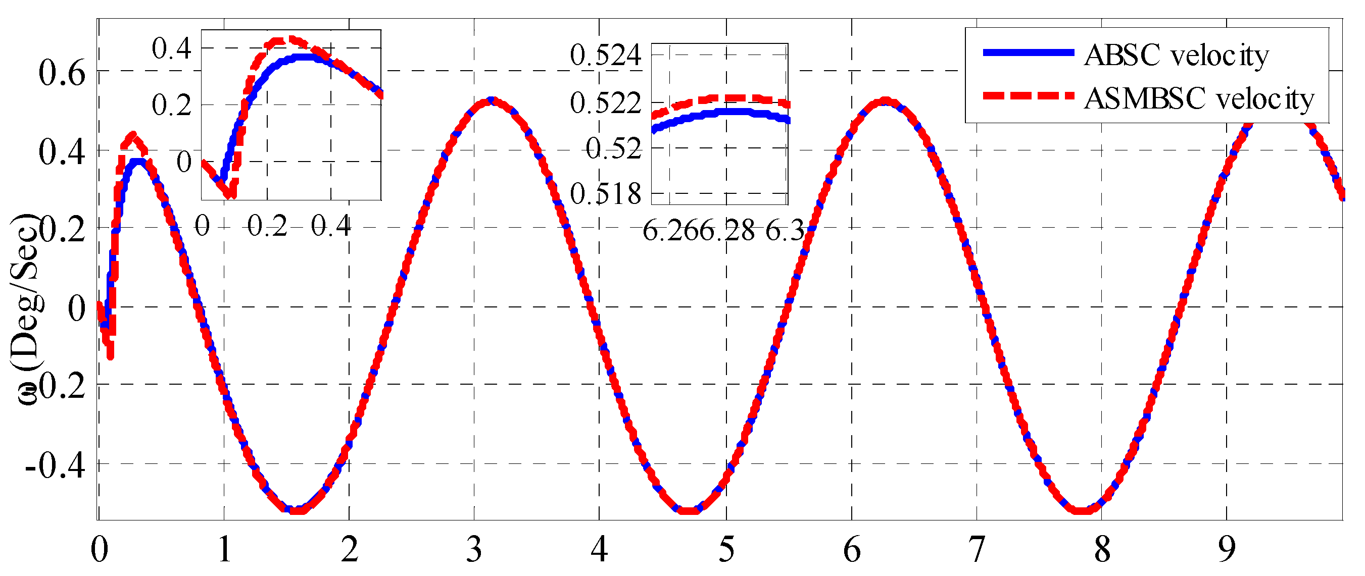
Figure 7 depicts the angular speed response for the throttle plate, where a faster response is shown with the adaptive sliding mode backstepping than that based on an adaptive backstepping controller.
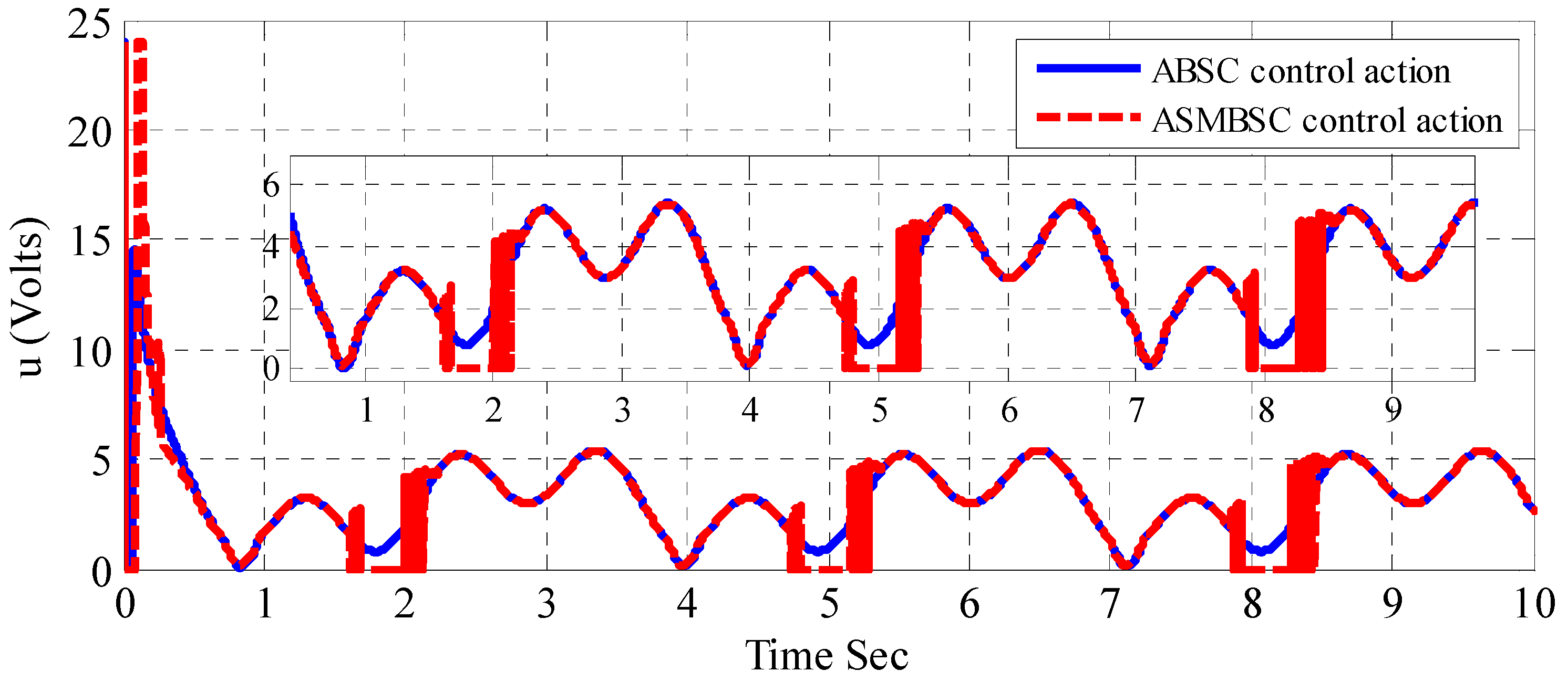
Figure 8 shows the behavior of control efforts given by both controllers, where the adaptive backstepping controller requires less control effort at transient than that needed by the adaptive sliding mode one. However, it is interesting to measure the root mean square of control effort over the entire simulation time. It has shown that the RMS of voltage signal required by adaptive sliding mode controller is less than required by adaptive backstepping controller as reported in Table 2. The main problem that has been observed with an adaptive sliding mode controller is the chattering behavior seen in its control effort envelope. However, Table 2 reports the performance numerical evaluation of both controllers.
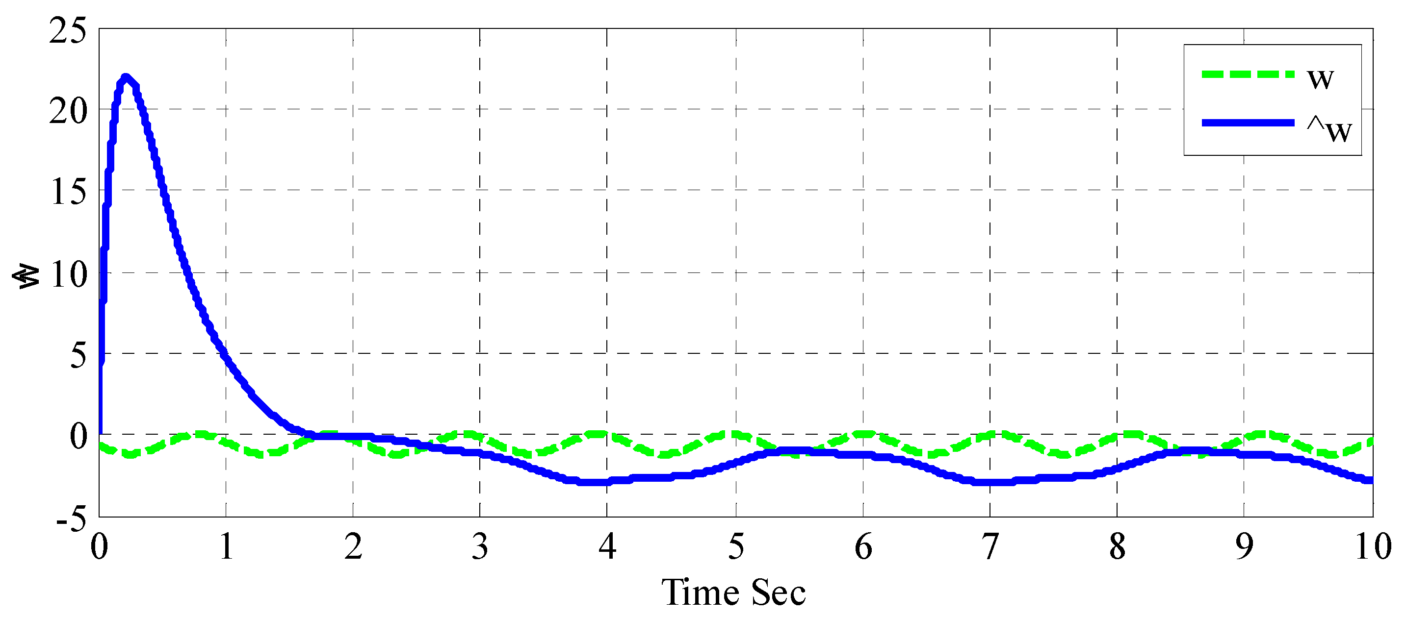
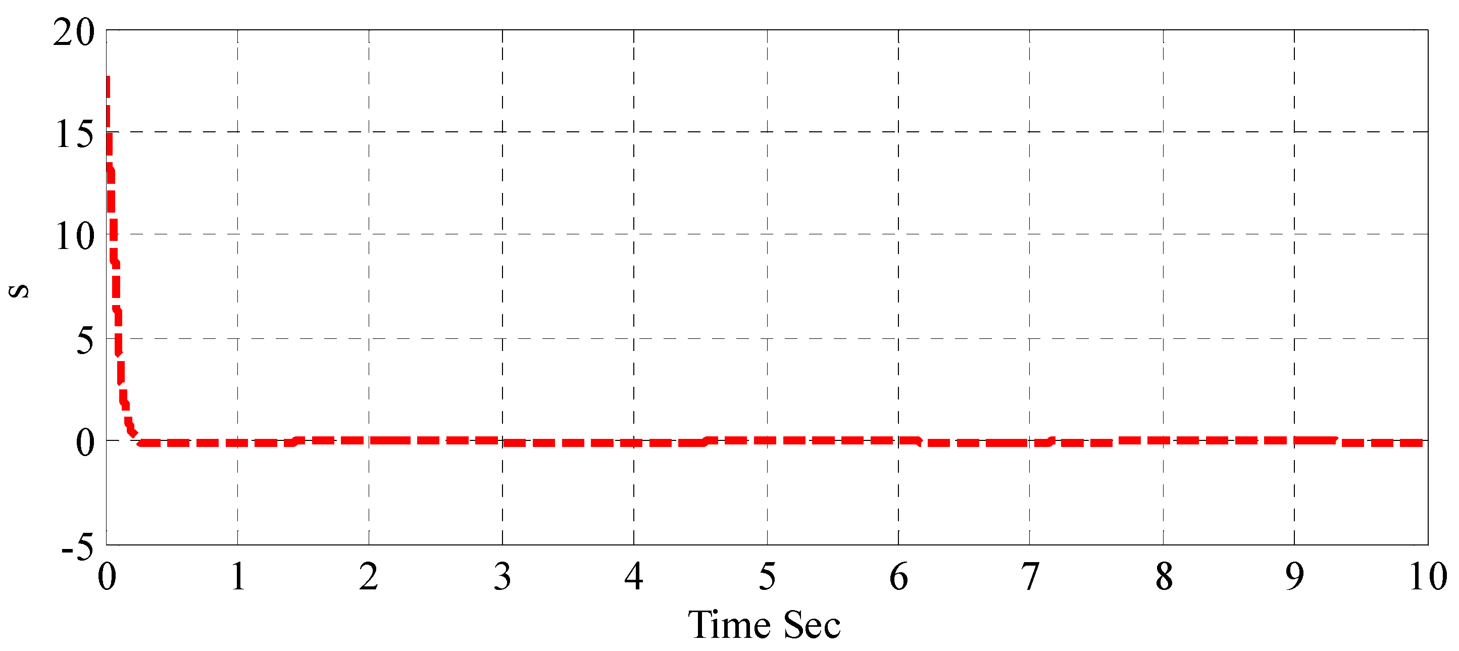
Figure 9 shows disturbance estimator response resulting from adaptive backstepping controller due to exerted disturbance. It is clear from the figure that the estimated disturbances represented by the adaptive gain tries to converge to the exerted disturbance. The sliding surface response is illustrated in Figure 10 shows, in which the sliding surface reaches zero dynamic error in a satisfactory and robust manner.
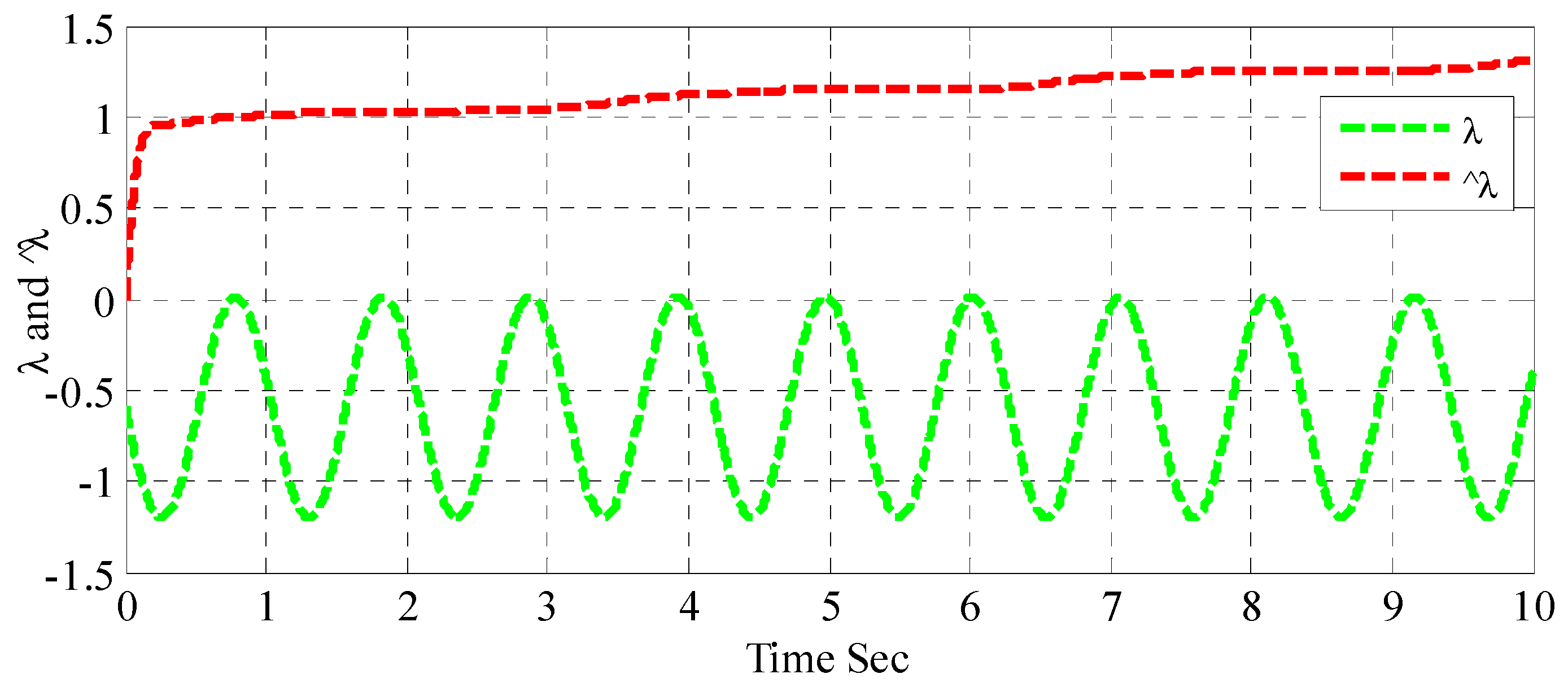
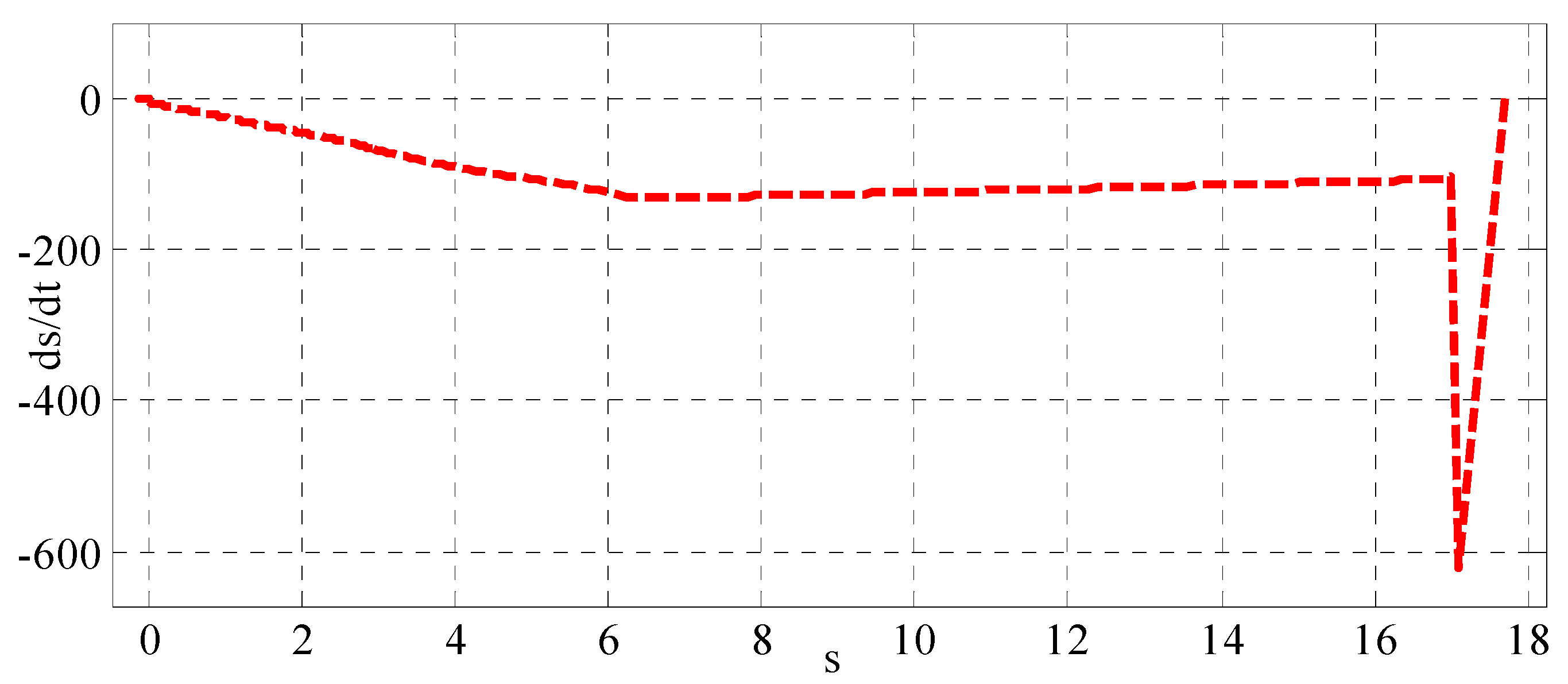
In response to applied disturbance, Figure 11 shows the response of disturbance estimator resulting from adaptive sliding mode backstepping controller. The figure indicates that in spite of the bounded adaptive gain obtained with this controller, the adaptive gain does not track the exerted disturbance as the performance given by adaptive backstepping controller. The reason behind this can be attributed to the task prescribed and designed for an adaptive sliding mode backstepping controller, where the bound of adaptive gain has been dominated rather than the tracking error. Figure 12 shows the adaptive sliding mode backstepping controller sliding surface versus its time derivative, which shows the big rate of change in the sliding surface as it approaches zero.

5. Conclusions

Three contributions has been highlighted by the present work. The main contribution is to develop two adaptive control algorithms based on the design of adaptive backstepping control strategy and the design of adaptive backstepping-based sliding mode control scheme, for angular position control of electronic throttle valve plate. The second contribution is to prove the stability of the electronic throttle valve system based on these two adaptive control schemes using Lyapunov theory. The third contribution is to present a comparison study between adaptive backstepping control and adaptive sliding mode backstepping control strategies.
The effectiveness of an adaptive backstepping controller and adaptive backstepping-based sliding mode controller have been examined using computer simulation based on MATLAB software. The performance comparison between the two adaptive controllers has been made and the simulated results showed that the adaptive sliding mode backstepping controller results in better performance in terms of both the transient and steady-state characteristics. However, the adaptive gain due to an adaptive backstepping controller showed closer convergence to real values, while an adaptive sliding mode backstepping controller could successfully estimate the upper bound of adaptive gain rather than tracking its real value. In an adaptive backstepping algorithm, the bound of disturbance is a prerequisite for the adaptive controller to work properly and estimate the disturbance. On the other hand, the adaptive backstepping sliding mode controller works to estimate this bound and therefore the problem of the need of the disturbance bound has been solved or avoided based on this controller.

Author Contributions

A.J.H. has supervised and examined the dynamic modeling, control design and stability analysis presented by A.H.H. Also, the evaluation of results, drawing of conclusions and text preparation and editing of the paper has been shared by both authors.

Funding

This research received no external funding.

Conflicts of Interest

The authors declare no conflict of interest.

References

  1. Loh, R.N.K.; Thanom, W.; Pyko, J.S.; Lee, A. Electronic Throttle Control System: Modeling, Identification and Model-Based Control Designs. Engineering 2013, 5, 587–600. [Google Scholar] [CrossRef]
  2. Schwartz, J.S. Design of an Automobile Accelerator/Brake Pedal Robot for Advanced Driver Assistance Systems. Ph.D. Thesis, Purdue University, West Lafayette, IN, USA, June 2017. [Google Scholar]
  3. Yadav, A.K.; Gaur, P.; Tripathi, S. Design and Control of an Intelligent Electronic Throttle Control System. In Proceedings of the IEEE International Conference on Energy Economics and Environment (ICEEE), Noida, India, 27–28 March 2015. [Google Scholar]
  4. Jiang, S.; Smith, M.H.; Kitchen, J. Optimization of PID Control for Engine Electronic Throttle System Using Iterative Feedback Tuning. SAE Technical Paper 2009. [Google Scholar] [CrossRef]
  5. Khalil, H.K. Nonlinear Systems; Prentice Hall: Upper Saddle River, NJ, USA, 2002. [Google Scholar]
  6. Krstic, M.; Kanellakopoulos, I.; Kokotovic, P.V. Nonlinear and Adaptive Control Design; Wiley: New York, NY, USA, 1995; Volume 222. [Google Scholar]
  7. Utkin, V.; Guldner, J.; Shi, J. Sliding Mode Control in Electro-Mechanical Systems; CRC Press: Boca Raton, FL, USA, 2009. [Google Scholar]
  8. Liu, J.; Wang, X. Advanced Sliding Mode Control for Mechanical Systems: Design, Analysis and MATLAB Simulation; Springer Science & Business Media: Berlin, Germany, 2012. [Google Scholar]
  9. Humaidi, A.J.; Hameed, A.H. PMLSM position control based on continuous projection adaptive sliding mode controller. Syst. Sci. Control Eng. 2018, 6, 242–252. [Google Scholar] [CrossRef]
  10. Humaidi, A.J.; Hameed, A.H. Robust MRAC for a Wing Rock Phenomenon in Delta Wing Aircrafts. Amirkabir Int. J. Model. Identif. Simul. Control 2017, 49, 113–122. [Google Scholar]
  11. Humaidi, A.J.; Hameed, A.H.; Hameed, M. Robust Adaptive Speed Control for DC Motor using Novel Weighted e-modified MRAC. In Proceedings of the IEEE International Conference on Power, Control, Signals and Instrumentation Engineering (ICPCSI-2017), Chennai, India, 21–22 September 2017. [Google Scholar]
  12. Chen, R.; Mi, L.; Tan, W. Adaptive fuzzy logic based sliding mode control of electronic throttle. J. Comput. Inf. Syst. 2012, 8, 3253–3260. [Google Scholar]
  13. Caruntu, C.; Vargas, A.; Acho Zuppa, L.; Pujol Vázquez, G. Adaptive-smith predictor for controlling an automotive electronic throttle over network. Int. J. Comput. Commun. Control 2018, 13, 151–161. [Google Scholar]
  14. Liu, X.; Vargas, A.N.; Yu, X.; Xu, L. Stabilizing two-dimensional stochastic systems through sliding mode control. J. Frankl. Inst. 2017, 354, 5813–5824. [Google Scholar] [CrossRef]
  15. Kurihara, N.; Yamaguchi, H. Adaptive Back-Stepping Control of Automotive Electronic Control Throttle. J. Softw. Eng. Appl. 2017, 10, 41. [Google Scholar] [CrossRef]
  16. Jiao, X.; Li, G.; Wang, H. Adaptive finite time servo control for automotive electronic throttle with experimental analysis. Mechatronics 2018, 53, 192–201. [Google Scholar] [CrossRef]
  17. Rui, B.; Yang, Y.; Wei, W. Nonlinear Backstepping Tracking Control for a Vehicular Electronic Throttle With Input Saturation and External Disturbance. IEEE Access 2018, 6, 10878–10885. [Google Scholar] [CrossRef]
  18. Nia, A.Z.; Nagamune, R. Switching Gain-Scheduled Proportional–Integral–Derivative Electronic Throttle Control for Automotive Engines. J. Dyn. Sys. Meas. Control 2018, 140, 071015. [Google Scholar]
  19. Yang, B.; Liu, M.; Kim, H.; Cui, X. Luenberger-sliding mode observer based fuzzy double loop integral sliding mode controller for electronic throttle valve. J. Process Control 2018, 61, 36–46. [Google Scholar] [CrossRef]
  20. Eski, İ.; Yıldırım, Ş. Neural network-based fuzzy inference system for speed control of heavy duty vehicles with electronic throttle control system. Neural Comput. Appl. 2017, 28, 907–916. [Google Scholar] [CrossRef]
  21. Wang, H.; Liu, L.; He, P.; Yu, M.; Do, M.T.; Kong, H.; Man, Z. Robust adaptive position control of automotive electronic throttle valve using PID-type sliding mode technique. Nonlinear Dyn. 2016, 85, 1331–1344. [Google Scholar] [CrossRef]
  22. Li, X.-J.; Yang, G.-H. Adaptive decentralized control for a class of interconnected nonlinear systems via backstepping approach and graph theory. Automatica 2017, 76, 87–95. [Google Scholar] [CrossRef]
  23. Togun, N.; Baysec, S. Nonlinear identification of a spark ignition engine torque based on ANFIS with NARX method. Expert Syst. 2016, 33, 559–568. [Google Scholar] [CrossRef]
  24. Lin, F.-J.; Chang, C.-K.; Huang, P.-K. FPGA-based adaptive backstepping sliding-mode control for linear induction motor drive. IEEE Trans. Power Electron. 2007, 22, 1222–1231. [Google Scholar] [CrossRef]
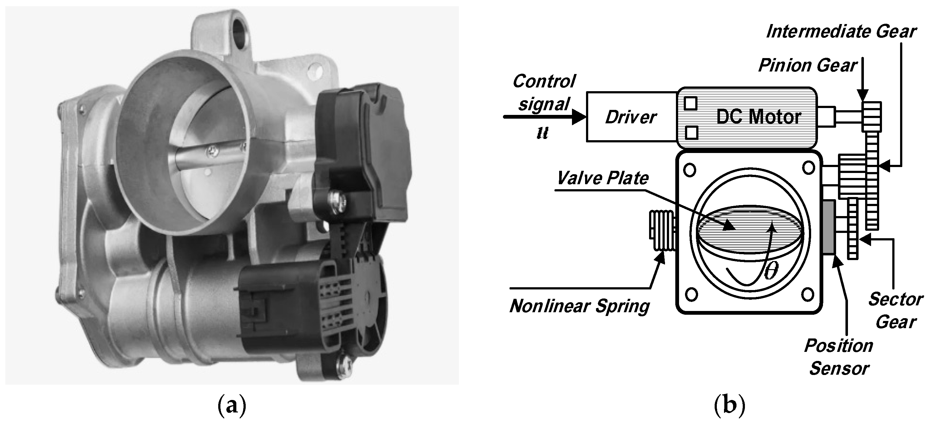
Figure 1. Electronic throttle valve (a) Actual Throttle Valve (b) Schematic Throttle valve.
Information 10 00065 g001
Figure 2. The schematic diagram of throttle valve.
Information 10 00065 g002
Figure 3. The schematic diagram of ETV system controlled by adaptive backstepping controller.
Information 10 00065 g003
Figure 4. The schematic diagram of ETV system controlled by adaptive sliding mode backstepping controller.
Information 10 00065 g004
Figure 5. The dynamic response of throttle valve angular position based adaptive backstepping and adaptive sliding mode backstepping controllers.
Information 10 00065 g005
Figure 6. Error response of plate angular position based on adaptive backstepping and adaptive sliding mode backstepping controllers.
Information 10 00065 g006
Figure 7. Plate angular speed response based on adaptive backstepping and adaptive sliding mode backstepping controllers.
Information 10 00065 g007
Figure 8. Control action response based on adaptive backstepping and adaptive sliding mode backstepping controllers.
Information 10 00065 g008
Figure 9. Adaptive backstepping disturbance estimator response with exerted disturbance.
Information 10 00065 g009
Figure 10. Sliding surface response based on adaptive sliding mode backstepping controller.
Information 10 00065 g010
Figure 11. Disturbance upper bound estimation response with exerted disturbance based on adaptive sliding mode backstepping controller
Information 10 00065 g011
Figure 12. Sliding surface derivative s ˙ (y-axis) versus sliding surface variable s (x-axis) based on adaptive sliding mode backstepping controller
Information 10 00065 g012
Table 1. Lists the numeric values of ETV parameters.
ParametersValueParametersValue
R2.1 K s p 0.32
L0.0017 N 4
K d 0.075 K t 0.072
B m 0.03 B t 0.007
B m o 6 × 10 3 B t o 4 × 10 3
J m 0.02 J t 0.01
Table 2. The performance report of controllers.
Tracking ErrorTimeVariance
0.535810
ABSC−0.6−0.020.050.040.270.2562
ASMBSC−0.0400.00100.10.1316
Control ActionTimeVariance
0.125810
ABSC14.51.11.20.13.710.3
ASMBSC24000.13.711.7