Value Engineering and Function Analysis: Frameworks for Innovation in Antenna Systems


Abstract
:1. Introduction
2. VE and FA Applications
3. Antenna Systems and FA Diagrams
4. Innovative Ideas for Antenna Systems
5. Conclusions
Author Contributions
Acknowledgments
Conflicts of Interest
References
- Miles, L.D. Techniques of value analysis and engineering. In Miles Value Foundation, 3rd ed.; CRC Press: Boca Raton, FL, USA, 2015; Available online: https://www.amazon.com/Techniques-Value-Analysis-Engineering-3rd-ebook/dp/B00UIDZRR0 (accessed on 16 April 2018).
- Webb, A. Value engineering. I. IET Eng. Manag. J. 1993, 3, 171. [Google Scholar] [CrossRef]
- Younker, D. Value Engineering: Analysis and Methodology; CRC Press: Boca Raton, FL, USA, 2003; Volume 30, Available online: https://www.amazon.com/Value-Engineering-Analysis-Methodology-Cost/dp/082470696X (accessed on 16 April 2018).
- Park, R. Value Engineering: A Plan for Invention; CRC Press: Boca Raton, FL, USA, 1998; Available online: https://www.amazon.com/Value-Engineering-Invention-Richard-Park/dp/157444235X (accessed on 16 April 2018).
- Altshuller, G.S. Creativity as an Exact Science. Gordon and Breach, 1984. Available online: https://www.amazon.com/Creativity-Science-Pocket-Mathematical-Library/dp/0677212305 (accessed on 16 April 2018).
- Mann, D. An Introduction to TRIZ: The Theory of Inventive Problem Solving. Creat. Innov. Manag. 2001, 10, 123–125. [Google Scholar] [CrossRef]
- Ilevbare, I.M.; Probert, D.; Phaal, R. A review of TRIZ, and its benefits and challenges in practice. Technovation 2013, 33, 30–37. [Google Scholar] [CrossRef]
- Huang, C.-Y.; Lin, Y.-H.; Tsai, P.-F. Developing a Rework Process for Underfilled Electronics Components via Integration of TRIZ and Cluster Analysis. IEEE Trans. Compon. Packag. Manuf. Technol. 2015, 5, 422–438. [Google Scholar] [CrossRef]
- Fartookzadeh, H.R.; Mokhtarianpour, M. Value engineering enriched by six sigma capabilities. Int. J. Curr. Life Sci. 2014, 4, 107. [Google Scholar]
- Balanis, C.A. Antenna Theory Analysis and Design; John Wiley & Sons: New York, NY, USA, 2005; Available online: https://www.amazon.com/Antenna-Theory-Analysis-Design-3rd/dp/047166782X (accessed on 16 April 2018).
- Wong, H.; Lin, Q.W.; Lai, H.W.; Zhang, X.Y. Substrate Integrated Meandering Probe-Fed Patch Antennas for Wideband Wireless Devices. IEEE Trans. Compon. Packag. Manuf. Technol. 2015, 5, 381–388. [Google Scholar] [CrossRef]
- Wheeler, H.A. A Helical Antenna for Circular Polarization. Proc. IRE 1947, 35, 1484–1488. [Google Scholar] [CrossRef]
- Fartookzadeh, M.; Armaki, S.H.M. Multi-band conical and inverted conical printed quadrifilar helical antennas with compact feed networks. AEU Int. J. Electron. Commun. 2016, 70, 33–39. [Google Scholar] [CrossRef]
- Saeid, G.M.; Khajepour, S.; Moradi, G. Quadrifilar Helix Antenna Using Compact Low-Cost Planar Feeding Circuit in Array Configuration. Prog. Electromagn. Res. 2016, 70, 91–98. [Google Scholar] [CrossRef]
- Fartookzadeh, M.; Armaki, S.H.M. Wide-beam spiral antenna with three folded arms fed by compact three-way Wilkinson power divider. Electron. Lett. 2016, 52, 587–588. [Google Scholar] [CrossRef]
- Fartookzadeh, M.; Armaki, S.H.M. Wide-beam spiral antennas with multi-folded arms and compact feed networks for satellite application. In Proceedings of the 2016 24th Iranian Conference on Electrical Engineering (ICEE), Shiraz, Iran, 10–12 May 2016. [Google Scholar] [CrossRef]
- Liao, S.; Xue, Q.; Bu, B.-L. Miniaturized UHF three-element sequential rotation array antenna. In Proceedings of the 2017 IEEE International Symposium on Antennas and Propagation & USNC/URSI National Radio Science Meeting, San Diego, CA, USA, 9–15 July 2017; pp. 2005–2006. [Google Scholar] [CrossRef]
- Targonski, S.D.; Pozar, D.M. Design of wideband circularly polarized aperture-coupled microstrip antennas. IEEE Trans. Antennas Propag. 1993, 41, 214–220. [Google Scholar] [CrossRef]
- Huang, J.C.P. Microstrip array with wide axial ratio bandwidth and single feed L.P. elements. In Proceedings of the Antennas and Propagation Society International Symposium, Vancouver, BC, Canada, 17–21 June 1985. [Google Scholar] [CrossRef]
- Evans, H.; Gale, P.; Aljibouri, B.; Lim, E.G.; Korolkeiwicz, E.; Sambell, A. Application of simulated annealing to design of serial feed sequentially rotated 2 × 2 antenna array. Electron. Lett. 2000, 36, 1987. [Google Scholar] [CrossRef]
- Fartookzadeh, M.; Armaki, S.H.M. Dual-Band Circularly-Polarized Monopulse Antenna System with Single Layer Patches and Separated Feed Networks. Prog. Electromagn. Res. C 2014, 55, 43–52. [Google Scholar] [CrossRef]
- Fartookzadeh, M.; Armaki, S.H.M. Serial-feed for a circular patch antenna with circular polarization suitable for arrays. Int. J. RF Microw. Comput. Aided Eng. 2014, 24, 529–535. [Google Scholar] [CrossRef]
- Kaschke, J.; Wegener, M. Gold triple-helix mid-infrared metamaterial by STED-inspired laser lithography. Opt. Lett. 2015, 40, 3986. [Google Scholar] [CrossRef] [PubMed]
- Fartookzadeh, M. Design of metamirrors for linear to circular polarization conversion with super-octave bandwidth. J. Mod. Opt. 2017, 64, 1854–1861. [Google Scholar] [CrossRef]
- Fartookzadeh, M. Multi-band metamirrors for linear to circular polarization conversion with wideband and wide-angle performances. Appl. Phys. B 2017, 123, 115. [Google Scholar] [CrossRef]
- Mailloux, R.J. Phased Array Antenna Handbook; Artech House: Boston, MA, USA, 2005; Volume 2, Available online: https://www.amazon.com/Antenna-Handbook-Antennas-Propagation-Library/dp/1580536891 (accessed on 16 April 2018).
- Pfeiffer, C.; Tomasic, B. Linear-to-Circular Polarizers for Multi-Octave Bandwidths and Wide Scan Angles at MM-Wave Frequencies Using Rotated Anisotropic Layers. Prog. Electromagn. Res. 2017, 79, 49–64. [Google Scholar] [CrossRef]
- Gerardo, P.; Page, J.E.; Arrebola, M.; Encinar, J.A. A Design Technique based on Equivalent Circuit and Coupler Theory for Broadband Linear to Circular Polarization Converters in Reflection or Transmission Mode. IEEE Trans. Antennas Propag. 2018. [Google Scholar] [CrossRef]
- Hidayath, M.; Soh, P.J.; Jamlos, M.F.; Hossain, T.M.; Ramli, M.N.; Al-Hadi, A.A.; Sheikh, R.A.; Hassan, E.S.; Yan, S. A crossed dodecagonal deployable polarizer on textile and polydimethylsiloxane (PDMS) substrates. Appl. Phys. A 2018, 124, 178. [Google Scholar] [CrossRef]
- Ruiz-Cruz, J.A.; Montejo-Garai, J.R.; Rebollar, J.M.; Montero, J.M. C-band orthomode transducer for compact and broadband antenna feeders. Electron. Lett. 2009, 45, 813. [Google Scholar] [CrossRef]
- Yoneda, N.; Miyazaki, M.; Matsumura, H.; Yamato, M. A design of novel grooved circular waveguide polarizers. In Proceedings of the IEEE MTT-S International Microwave Symposium Digest (Cat. No.00CH37017), Boston, MA, USA, 11–16 June 2000. [Google Scholar] [CrossRef]
- Zhang, L.; Donaldson, C.R.; He, W. Design and measurement of a polarization convertor based on a truncated circular waveguide. J. Phys. D Appl. Phys. 2012, 45, 345103. [Google Scholar] [CrossRef]
- Behe, R.; Brachat, P. Compact duplexer-polarizer with semicircular waveguide (antenna feed). IEEE Trans. Antennas Propag. 1991, 39, 1222–1224. [Google Scholar] [CrossRef]
- Wang, H.S.; Che, Z.H.; Wang, M.J. A three-phase integrated model for product configuration change problems. Expert Syst. Appl. 2009, 36, 5491–5509. [Google Scholar] [CrossRef]
- Ibusuki, U.; Kaminski, P.C. Product development process with focus on value engineering and target-costing: A case study in an automotive company. Int. J. Prod. Econ. 2007, 105, 459–474. [Google Scholar] [CrossRef]
- Tang, P.; Bittner, R.B. Use of Value Engineering to Develop Creative Design Solutions for Marine Construction Projects. Pract. Period. Struct. Des. Constr. 2014, 19, 129–136. [Google Scholar] [CrossRef]
- Mousakhani, E.; Yavarkhani, M.; Sohrabi, S. Selecting an appropriate alternative for a major infrastructure project with regard to value engineering approach. J. Eng. Des. Technol. 2017, 15, 395–416. [Google Scholar] [CrossRef]
- Mahdi, F.; Ghaffarian, M.S.; Zamani, A.; Fatemi, R. Rectangular Horn Antennas with Limiting Plates for Symmetrical Pattern and Beam Efficiency Improvement. Prog. Electromagn. Res. C 2016, 69, 63–71. [Google Scholar] [CrossRef]
- Gibson, H.J.; Thomas, B.; Rolo, L.; Wiedner, M.C.; Maestrini, A.E.; de Maagt, P. A Novel Spline-Profile Diagonal Horn Suitable for Integration into THz Split-Block Components. IEEE Trans. Terahertz Sci. Technol. 2017. [Google Scholar] [CrossRef]
- Barton, D.K. The 1993 Moscow Air Show. Microw. J. 1994, 37, 24–40. [Google Scholar]
- Grossman, E.N.; Luukanen, A.; Miller, A.J. Terahertz active direct detection imagers. Terahertz Mil. Secur. Appl. II 2004. [Google Scholar] [CrossRef]
- Doumanis, E.; Goussetis, G.; Gomez-Tornero, J.L.; Cahill, R.; Fusco, V. Anisotropic Impedance Surfaces for Linear to Circular Polarization Conversion. IEEE Trans. Antennas Propag. 2012, 60, 212–219. [Google Scholar] [CrossRef]
- Kildal, P.-S. Factorization of the feed efficiency of paraboloids and Cassegrain antennas. IEEE Trans. Antennas Propag. 1985, 33, 903–908. [Google Scholar] [CrossRef]
- Fartookzadeh, M.; Armaki, S.H.M. Dual-Band Reflection-Type Circular Polarizers Based on Anisotropic Impedance Surfaces. IEEE Trans. Antennas Propag. 2016, 64, 826–830. [Google Scholar] [CrossRef]
- Allan, D.; Kingdon, D.; Murrin, K.; Rudkin, D. What If: How to Start a Creative Revolution at Work; Wiley Capstone: New York, NY, USA, 1999; Available online: https://www.amazon.com/What-If-Start-Creative-Revolution/dp/1841120685 (accessed on 16 April 2018).
- Zhang, Y.-X.; Liu, Q.; Hong, R.; Pan, P.; Deng, Z. A novel monopulse angle estimation method for wideband LFM radars. Sensors 2016, 16, 817. [Google Scholar] [CrossRef] [PubMed]
- Pozar, D.M.; Targonski, S.D.; Pokuls, R. A shaped-beam microstrip patch reflectarray. IEEE Trans. Antennas Propag. 1999, 47, 1167–1173. [Google Scholar] [CrossRef]
- Han, C.; Huang, J.; Chang, K. Cassegrain offset subreflector-fed X/Ka dual-band reflectarray with thin membranes. IEEE Trans. Antennas Propag. 2006, 54, 2838–2844. [Google Scholar] [CrossRef]
- Fartookzadeh, M.; Armaki, S.H.M. Enhancement of Dual-Band Reflection-Mode Circular Polarizers Using Dual-Layer Rectangular Frequency Selective Surfaces. IEEE Trans. Antennas Propag. 2016, 64, 4570–4574. [Google Scholar] [CrossRef]
- Orr, R.; Goussetis, G.; Fusco, V.; Cahill, R.; Zelenchuk, D.; Pal, A.; Saenz, E.; Simeoni, M.; Drioli, L.S. Circular polarization frequency selective surface operating in Ku and Ka band. In Proceedings of the 8th European Conference on Antennas and Propagation (EuCAP 2014), Hague, The Netherlands, 6–11 April 2014. [Google Scholar] [CrossRef]
- Tamayama, Y.; Yasui, K.; Nakanishi, T.; Kitano, M. A linear-to-circular polarization converter with half transmission and half reflection using a single-layered metamaterial. Appl. Phys. Lett. 2014, 105, 021110. [Google Scholar] [CrossRef]
- Wang, J.; Du, B.; Wu, Y.; He, Y. A Wideband Waveguide Diplexer for the Extend C-Band Antenna Systems. Prog. Electromagn. Res. 2016, 69, 73–82. [Google Scholar] [CrossRef]
- Leal-Sevillano, C.A.; Cooper, K.B.; Ruiz-Cruz, J.A.; Montejo-Garai, J.R.; Rebollar, J.M. A 225 GHz Circular Polarization Waveguide Duplexer Based on a Septum Orthomode Transducer Polarizer. IEEE Trans. Terahertz Sci. Technol. 2013, 3, 574–583. [Google Scholar] [CrossRef]
- Dahmus, J.B.; Gonzalez-Zugasti, J.P.; Otto, K.N. Modular product architecture. Des. Stud. 2001, 22, 409–424. [Google Scholar] [CrossRef]
- Martin, M.V.; Ishii, K. Design for variety: Developing standardized and modularized product platform architectures. Res. Eng. Des. 2002, 13, 213–235. [Google Scholar] [CrossRef]


| Functionality Available from Components | Component | Advantages | Limitations | |
|---|---|---|---|---|
| 1 | Propagating electromagnetic waves | Antennas with LP | Easy to design, high performance (bandwidth, gain, efficiency, etc.) | Cannot be used as the transmitter and receiver simultaneously, only receives incoming waves with similar polarizations |
| Circularly polarized antennas | Receives incoming waves with all direction of linear polarizations | Cannot be used as the transmitter and receiver simultaneously, complicated design, limited performance (bandwidth, gain, efficiency, etc.) | ||
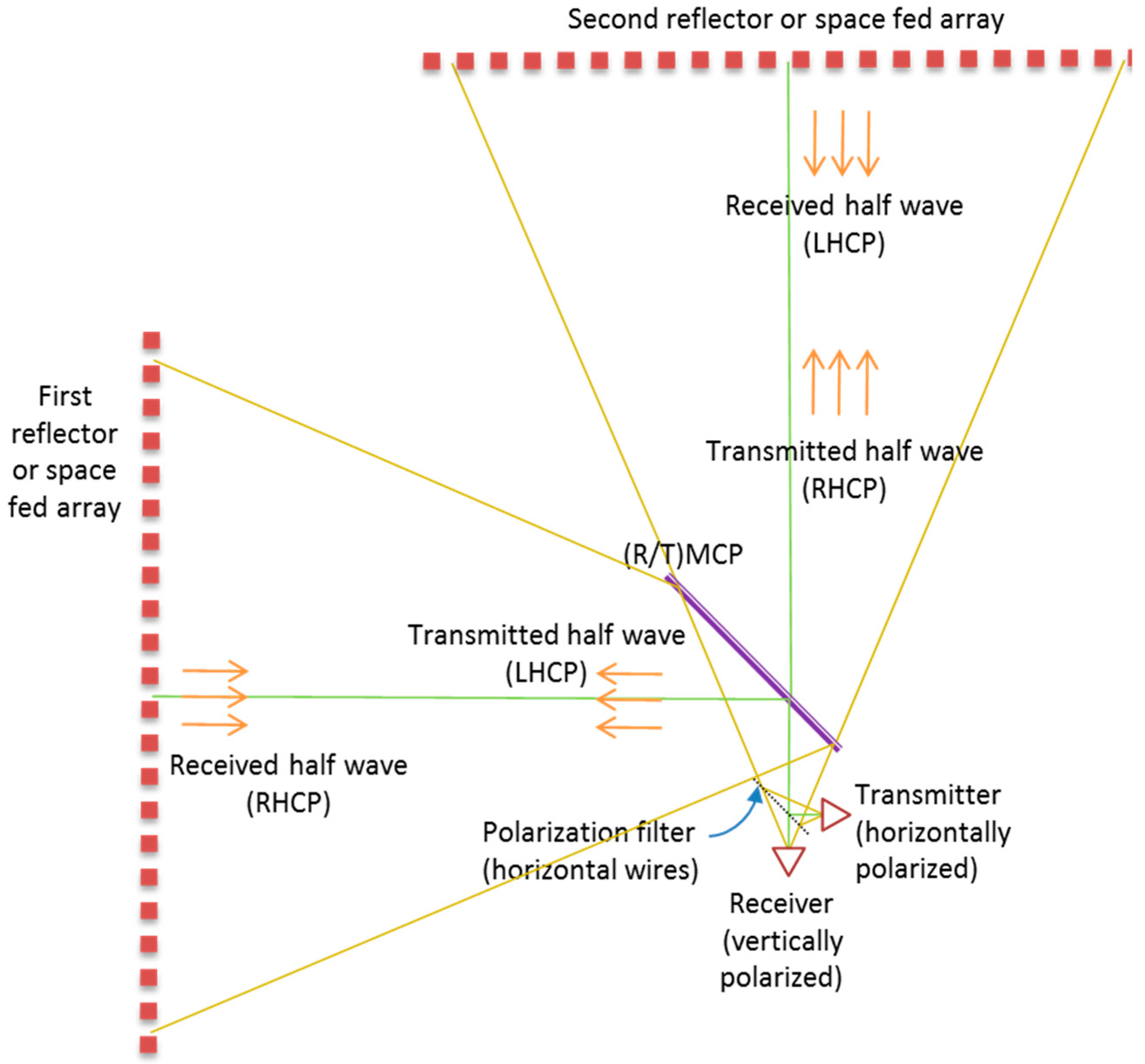
| 2 | Converting linearly polarized waves to CP and vice versa (converting, for example, vertically polarized waves to RHCP and horizontally polarized waves to LHCP) | Metamaterial-based TMCPs | Situated at right angle to the propagation angle of the incident wave, additional functionalities can be obtained | Limited performance (bandwidth, transmission loss, etc.), increased reflections for the antennas, bulky, requires standings |
| Metamaterial-based RMCPs | High performance (bandwidth, transmission loss, etc.), reduced reflections in the direction of incoming waves, additional functionalities can be obtained | Tilting required, bulky, requires standings | ||
| Waveguide linear to circular polarizers | Reduced dimensions, can be integrated with the antenna | High sensitivity, limited bandwidth, difficult for additional functionalities of the feed such as trackers, etc. | ||
| 3 | Separating the cross-polarity of the waves with LP | LP filters | Simple structure, wideband, low cost | Bulky, requires standings |
| OMTs | Reduced dimensions, can be integrated with the antenna | Encountered difficulties for additional functionalities of the feed such as trackers, etc. | ||
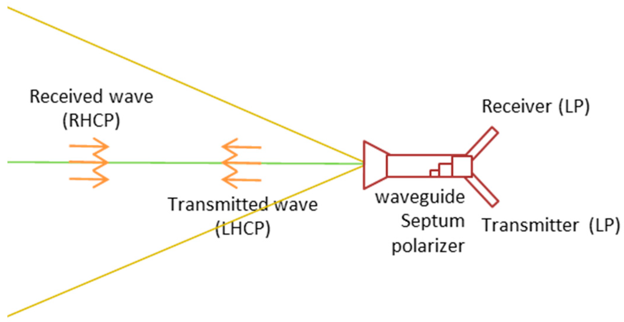
| 4 | 2 and 3 (converting first input to RHCP wave and the second one to LHCP and vice versa, directly) | Septum circular polarizers | Very reduced dimensions, can be integrated with the antenna | High sensitivity, limited bandwidth, difficult for additional functionalities of the feed such as trackers, etc. |
| 5 | Increasing gain and reducing the beamwidth | Reflectors with physical shapes | Reduced costs (usually), easily understandable structure | Required physical movement for changing the beam direction, difficult for additional functionalities |
| Lens with physical shapes | Easily understandable structure, no blockage loss | Weighty, costly, requires physical movement for changing the beam direction, difficult for additional functionalities | ||
| Reflect arrays | Weight can be reduced, can be used for electrically controlling the wave (without physical movements) | Advanced expertise is required for design, usually used for passive arrays | ||
| Lens arrays | Weight can be reduced, can be used for electrically controlling the wave (without physical movements), no blockage loss | Advanced expertise is required for design |
© 2018 by the authors. Licensee MDPI, Basel, Switzerland. This article is an open access article distributed under the terms and conditions of the Creative Commons Attribution (CC BY) license (http://creativecommons.org/licenses/by/4.0/).
Share and Cite
Fartookzadeh, H.R.; Fartookzadeh, M. Value Engineering and Function Analysis: Frameworks for Innovation in Antenna Systems. Challenges 2018, 9, 20. https://doi.org/10.3390/challe9010020
Fartookzadeh HR, Fartookzadeh M. Value Engineering and Function Analysis: Frameworks for Innovation in Antenna Systems. Challenges. 2018; 9(1):20. https://doi.org/10.3390/challe9010020
Chicago/Turabian StyleFartookzadeh, Hamid Reza, and Mahdi Fartookzadeh. 2018. "Value Engineering and Function Analysis: Frameworks for Innovation in Antenna Systems" Challenges 9, no. 1: 20. https://doi.org/10.3390/challe9010020
APA StyleFartookzadeh, H. R., & Fartookzadeh, M. (2018). Value Engineering and Function Analysis: Frameworks for Innovation in Antenna Systems. Challenges, 9(1), 20. https://doi.org/10.3390/challe9010020