Article

Hydrodynamic Sensitivity of Moored and Articulated Multibody Offshore Structures in Waves

Institute of Ship Technology, Ocean Engineering and Transport Systems, University of Duisburg-Essen, 47057 Duisburg, Germany
*
Author to whom correspondence should be addressed.
J. Mar. Sci. Eng. 2021, 9(9), 1028; https://doi.org/10.3390/jmse9091028
Submission received: 3 August 2021 / Revised: 13 September 2021 / Accepted: 16 September 2021 / Published: 18 September 2021
(This article belongs to the Special Issue Mooring of Floating Offshore Structures)

Abstract

:
Within the framework of Space@Sea project, an articulated modular floating structure was developed to serve as building blocks for artificial islands. The modularity was one of the key elements, intended to provide the desired flexibility of additional deck space at sea. Consequently, the layout of a modular floating concept may change, depending on its functionality and environmental condition. Employing a potential-flow-based numerical model (i.e., weakly nonlinear Green function solver AQWA), this paper studied the hydrodynamic sensitivity of such multibody structures to the number of modules, to the arrangement of these modules, and to the incident wave angle. Results showed that for most wave frequencies, their hydrodynamic characteristics were similar although the floating platforms consisted of a different number of modules. Only translational horizontal motions, i.e., surge and sway, were sensitive to the incident wave angle. The most critical phenomenon occurred at head seas, where waves traveled perpendicularly to the rotation axes of hinged joints, and the hinge forces were largest. Hydrodynamic characteristics of modules attached behind the forth module hardly changed. The highest mooring line tensions arose at low wave frequencies, and they were caused by second-order mean drift forces. First-order forces acting on the mooring lines were relatively small. Apart from the motion responses and mooring tensions, forces acting on the hinge joints governed the system’s design. The associated results contribute to design of optimal configurations of moored and articulated multibody floating islands.

1. Introduction

The majority of the world’s population lives in coastal areas where space has always been at a premium because available land space is limited [1]. In the near future, waterfronts may reclaim or change the utilization of large parts of existing land spaces as sea levels rise with global warming. With an increasing need for affordable deck space at sea, the concept of a very large offshore floating structure (VLFS) came into being. This structure embodies an effective platform for the development of marine resources. Large oil and gas storage facilities [2], floating airports [3], offshore tourist resorts [4], fish farming factories [5], and marine renewable energy platforms [6] are typical examples. Lamas-Pardo et al. [7] documented a review of VLFS concepts for coastal and offshore uses. Due to its large dimensions, the main technical challenge associated with a hydrodynamic analysis of a VLFS is the adherent hydroelastic effect [8]. Although a number of VLFS projects have been proposed for various purposes worldwide, actual implementation of a VLFS is limited due to its manufacturing complexity and transportation constraints, together with policy issues and regulations [9].
A standard floating modular concept, which can be employed for various functions in single or multipurpose islands, was developed within the framework of the European research project Space@Sea. By following the analogy of standardization to enlarge a floating structure using a multitude of smaller modules, this project intended to significantly reduce building and installation costs and to provide the desired flexibility of additional deck space at sea [1]. Unlike a traditional VLFS, which must endure significant bending moments and considerable shear force due to its large size, a modular floating structure (MFS) is able to cope with large internal forces. Additional benefits are lower transportation, fabrication, and installation costs and the potential expansion of practical VLFS systems [10]. Nevertheless, size, shape, and joint design to connect the basic modular units should be carefully investigated to meet a mix of specific requirements [11]. Riggs and Ertekin [12] used two-dimensional and three-dimensional approximate hydroelasticity theories to predict the dynamic responses of a MFS consisting of different number of modules in regular waves, where a linearized stiffness matrix represented the connecting system. The effect of fluid interaction between modules on the dynamic response of the MFS was shown to be weak, and their results obtained by ignoring module-fluid-module interaction agreed well with those that included this interaction. Gao et al. [13] considered the hydroelastic response of a pontoon-type MFS with a flexible line connection. Depending on wavelength, hinge and semi-rigid line connections were found to be effective in reducing hydroelastic response and the associated stresses. Results of Fu et al. [14] showed that, compared to the responses of rigid connectors, flexible hinge-type or semi-rigid connectors can effectively reduce the hydroelastic responses of an MFS system. To investigate the optimum configurations of an MFS, Michailides et al. [15] studied three different module layouts, with the connectors modeled as linearized springs. Their results indicated that the grid layout directly affects the internal loads in the connectors as well as the responses of the modules. Effects of connector stiffness on the hydroelasitc responses and internal loads of an MFS were addressed also by Wang et al. [16].
Most previous studies treated the connectors either as independent linear springs in all degrees-of-freedom, or they discretized the stiffness matrix using the finite element method, thereby ignoring coupling effects between module motions and nonlinear restoring characteristics [17,18]. These investigations focused on the effects of the connectors’ features, such as stiffness and damping, on hydrodynamic or hydroelastic responses of an MFS. The analysis of a complex multibody interconnected system must consider not only its multibody hydrodynamics, but also the restrictions imposed by the connectors. Various articulation techniques, such as hinge, prismatic, cylindrical, and screw joints [19] are possible. Newman [20], for example, treated wave effects on an array of five hinged rigid modules; Ghesmi et al. [21], on articulated ships; Rogne [22], on hinged wave energy converters; Diamantoulaki and Angelides [23], on hinged floating breakwaters; and Zhu et al. [24], on a floating offshore wind turbine with hinged structures. Reviewing research on MFSs showed that the hydrodynamic sensitivity of articulated multibody offshore structures has hardly been scrutinized, whereas hydrodynamics of multibody interactions and restrictions from mechanically modeled connectors has been considered. For a MFS consisting of multiple bodies, the incoming waves, after being scattered by one of the bodies, become the incident waves for the other bodies, thereby generating multiple scatting effects between bodies. Apart from multibody interactions, constraints of articulated hinges between neighboring bodies cause additional complexities that must be accounted for in the analysis.
To design reasonable configurations of such floating islands, we investigated the hydrodynamic sensitivity of hinged multibody structures, specifically, the number of modules, the modules’ arrangement, and the incident wave angle, using a weakly nonlinear potential-flow approach. The adopted numerical model accounted for hydrodynamic interactions between neighboring modules and nonlinear restrictions imposed by articulated connections. The review of research on MFS shows that attempts undertaken to comprehensively investigate the hydrodynamic sensitivity of moored and articulated MFS are still missing, which is filled by this paper. The present study begins with the validation of the adopted numerical model for predicting the motion responses of one floating module in waves, using previous computational fluid dynamics (CFD) simulations, and experimental measurements. Then the sensitivity study was conducted for five test cases in head waves, where articulated floating structures with a different number of modules were investigated. The considered configurations were connected via hinge joints, and positioned by four symmetrical mooring lines. The considered configurations were simulated for multiple wave frequencies, and the associated results were discussed in terms of motion responses and forces acting on the mooring lines, as well as the hinge joints. In the matter of the hydrodynamic sensitivity to the module’s arrangement, we considered two configurations, namely, the chain configuration and the parallel configuration, consisting of four and eight modules, respectively. This was followed by the study of hydrodynamic sensitivity to incident wave angles, where three corner configurations consisting of three, five, and seven modules were addressed. Finally, the main findings and limitations of present study are summarized and discussed, which should be carefully taken into consideration for the optimum arrangement of a moored and articulated MFS.

2. Numerical Approach

We employed the commercial software package AQWA [25], a weakly nonlinear potential-flow solver, for our computations. Specifically, we used two packages from its kernel, namely, the hydrodynamic diffraction module and the hydrodynamic response module, which enabled idealizing coupled articulated connections between bodies. The diffraction package computed the primary hydrodynamic variables required for complex motion and response analyses by solving the Green function for irrotational flow based on a boundary element panel method [26] in the frequency domain. The response package performed the dynamic analysis in the time domain by deriving the impulsive response from the diffraction module and solving the equation of motion by means of the state-space method, where nonlinear Froude-Krylov and hydrostatic forces were estimated under instantaneous incident wave surface. Second-order wave loads are included, based on the full set of quadratic transfer functions (QTFs). A heuristic approach [27] accounts for wave drift damping and effects of current on second-order wave drift loads. The articulated hinge between two floating bodies was modeled by adding kinematic constraints to the equations of motion, using a library of predefined coupling types. The forces and moments in these articulated connectors were determined by computing sectional loads at the articulation section. Recall that the hinged joints were used in present study, where articulated structures were allowed to rotate around the axis of the hinged joint.
In the case of articulation between floating bodies, denoting x g j , x g k as the locations of the centers of gravity of the j-th and k-th bodies, respectively, and x p as the connecting point in the globe coordinate system, the vectors between the joint point and the j-th and k-th structures are written as follows:
r j = x p x g j = x j , y j , z j
r k = x p x g k = x k , y k , z k
Further denoting the translational and rotational movements of these two linked structures as ( u j , Θ j ) and ( u k , Θ k ) , the unit vectors of the local articulation axes with respect to the global axes are given as:
e 1 = ( e 11 , e 21 , e 31 )
e 2 = ( e 12 , e 22 , e 32 )
For the locked constraint case, the constraint boundary conditions in the local articulation frame are expressed as follows:
( u j + Θ j × r j ) · e m = ( u k + Θ k × r k ) · e m
Θ j · e m = Θ k · e m ( m = 1 , 3 )
Introducing the matrix form, the above equations can be expressed as follows:
E T E T R j 0 E T U j E T E T R k 0 E T U k = 0
with
E = e 11 e 12 e 13 e 21 e 22 e 23 e 31 e 32 e 33 , R j = 0 z j y j z j 0 x j y j x j 0 , R k = 0 z k y k z k 0 x k y k x k 0
U j = ( u j , Θ j ) , U k = ( u k , Θ k )
For the hinged constraint case, in which the rotation about the local articulation y-axis is free, the boundary conditions are similarly given by:
E T E T R j 0 G T U j E T E T R k 0 G T U k = 0
with
G = e 11 0 e 13 e 21 0 e 23 e 31 0 e 33
Equation (5) for the locked constraint case can be converted into the same form of Equation (7) by simply defining G=E. From the above discussion, the boundary conditions of all constraint types can be defined by Equation (7), differing only in the form of the G matrix. Furthermore, by denoting:
H j = E T E T R j 0 G T
Equation (7) is rewritten as follows:
H j U j H k U k = 0
Denoting the constraint reaction force/moment matrix acting on the j-th structure at the articulation point in the local articulation axes as R c , the motion, including the reaction forces and moments of the two linked structures, can be determined from:
K j j K j k H j T K k j K k k H k T H j H k 0 U j U k R c = F j F k 0
where K j j K j k K k j K k k is the total stiffness matrix of these two structures, and F j and F k are the forces and moments acting on the j-th and k-th structures, respectively.

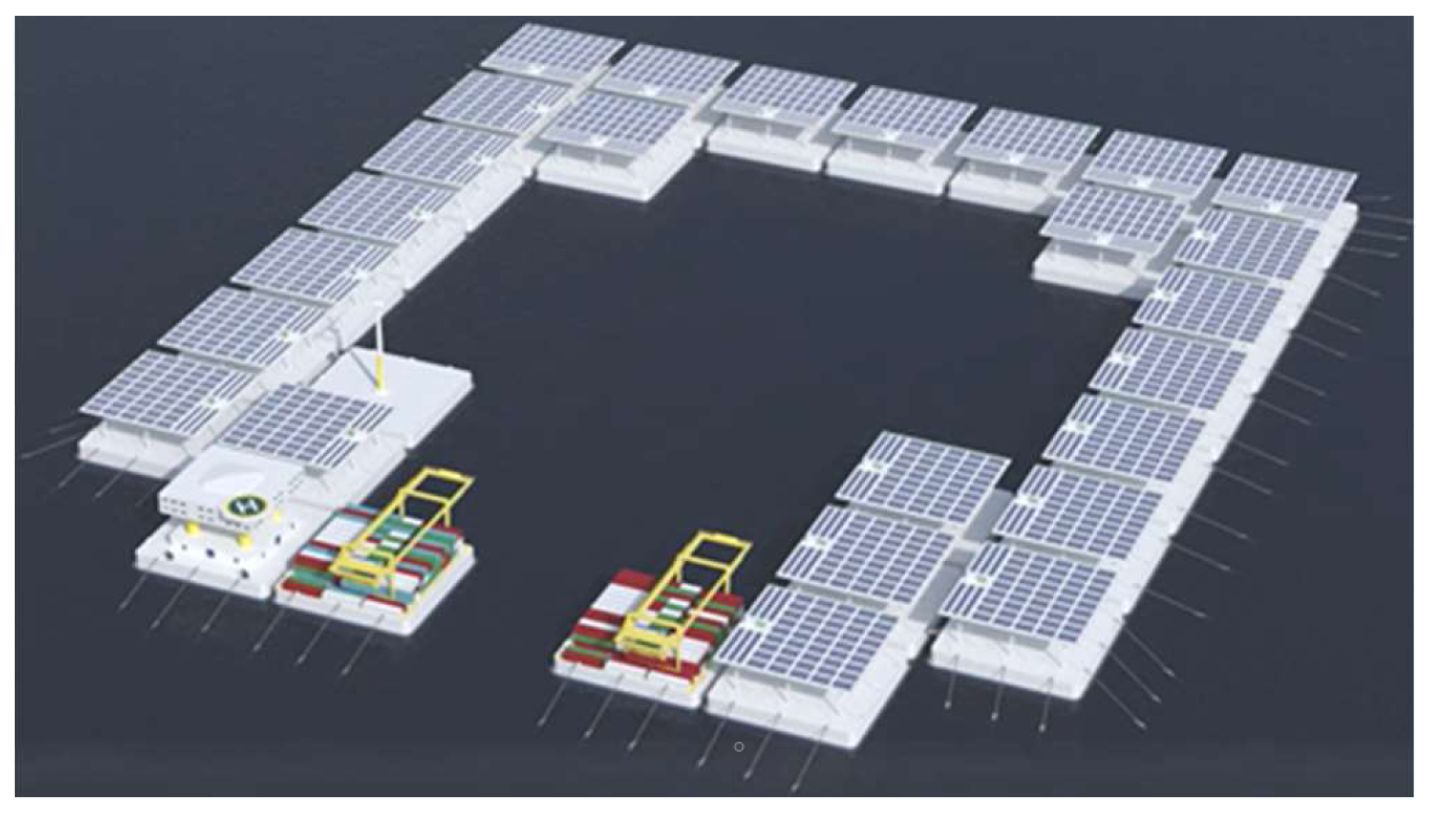
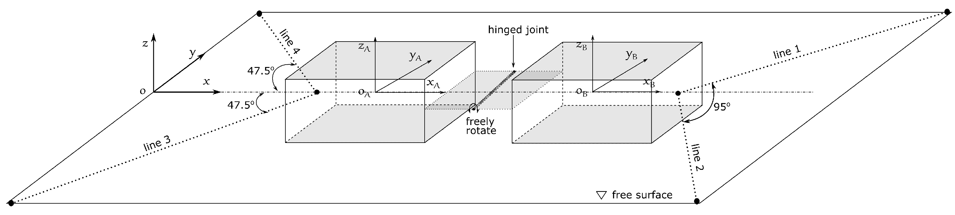
3. Test Case Description

To design reasonable configurations of such a floating island and to provide benchmark data for the validation of numerical codes, model tests under relevant environment conditions were experimentally investigated in the towing tank of Delft University [28]. These tests comprised three body shapes and different coupled configurations. It was concluded that the cuboid module shape scored best, and its dimension was defined based on the inherent advantages regarding modularity, building ease and transport and installation effort [11]. Table 1 lists properties of such a floating module at its basic design stage. An application of such floating modules for the Energyhub@Sea is shown in Figure 1, which was intended to support the maintenance of nearby floating wind farms.
As illustrated in Figure 2, hinge joints connected the modules at the calm waterline, and these modules were situated a distance of 5.0 m apart from each other. The hinges allowed only rotational motions between modules and the axes of the hinged joints are parallel to y-axis. The water depth was set to 35.0 m, and second-order Stokes wave theory generated the waves. The mooring setup, similar to the one used for model tests [28], was represented by a linear spring model. At each end side, two symmetric mooring lines at an angle of 95 connected the central and rear modules to vertical piles. Mooring anchor points were located on these piles. Pretensions were applied to the mooring lines and the main particulars of a mooring line is listed in Table 2. There particulars were adapted from the model test [28] into the equivalent values at the full scale. It is worth mentioning that all hinged joints and mooring lines were placed at the free surface (i.e., the horizontal plane o- x y ). To optimize the configurations of floating island concepts, we tested three different configurations, here named the chain configuration (C-type), the parallel configuration (P-type), and the corner configuration (L-type). Figure 3 presents a schematic top view of these configurations, including the global x-y-z coordinate system, the numbering of the modules, parts of the attached mooring lines, and the arrow pointing in the direction of waves propagating at a heading angle of 180 .

4. Results

This section starts with the validation of the adopted numerical model using experimentally measured results from Thill [28] and computational fluid dynamics (CFD) simulations from Seithe and el Moctar [30]. Then the hydrodynamic sensitivity of moored and hinged multibody structures in waves, specifically, the number of modules, the modules’ arrangement, and the incident wave angle were investigated using the validated numerical model.

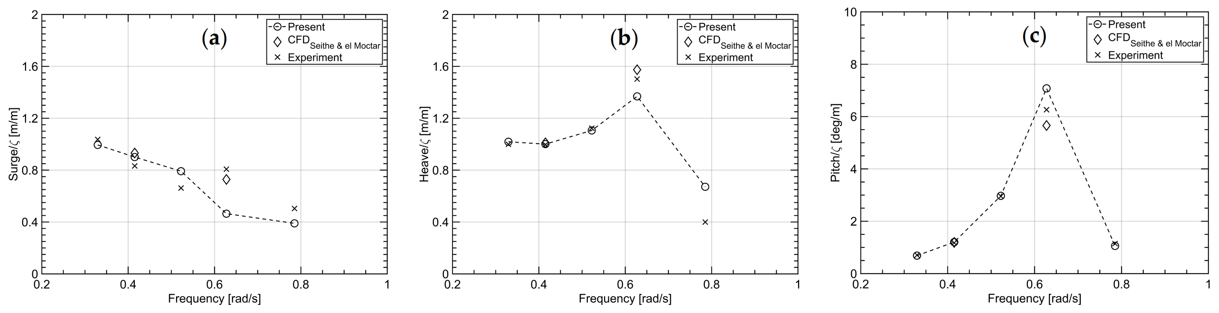
4.1. Validation of the Numerical Model

The validation of the adopted numerical model was conducted for one floating module subject to regular waves of different frequencies, positioned symmetrically by four mooring lines, i.e., identical to the chain-type in Figure 3. The incident waves propagated at an encounter angle of 180 of the x-axis, representing the head wave conditions. Figure 4 plots the computed and measured motion responses in surge, heave and pitch under regular head waves over frequencies, where ζ denotes wave amplitude. Symbol ∘ denote our results obtained from present weakly nonlinear time-domain simulations; symbol , results from CFD simulations of a previous study [30]; symbol ×, experimental measurements. As seen, our results obtained from present simulations generally agreed well with the results obtained from the CFD simulations and experimental measurements at frequencies away from the resonance region. However, at wave frequencies close to the module’s natural frequencies of 0.628 rad/s, the CFD results and the experimental measurements deviate slightly from our predictions. Specifically, the present potential-flow solver underpredicted the translational motions (surge and heave), but overpredicted the rotational motion (pitch). As expected, due to the relatively small wave amplitude, viscous effects were unimportant as diffraction effects dominated the flow. Overall, our numerical predictions compared reasonably well to the experimental measurements, except for the responses near the module’s natural frequencies. Although the inaccurate predictions of the floating modules in resonance conditions are the drawbacks of present numerical model, the overall good agreements between present simulations to CFD simulations and experimental measurements give confidence for subsequent sensitivity studies.

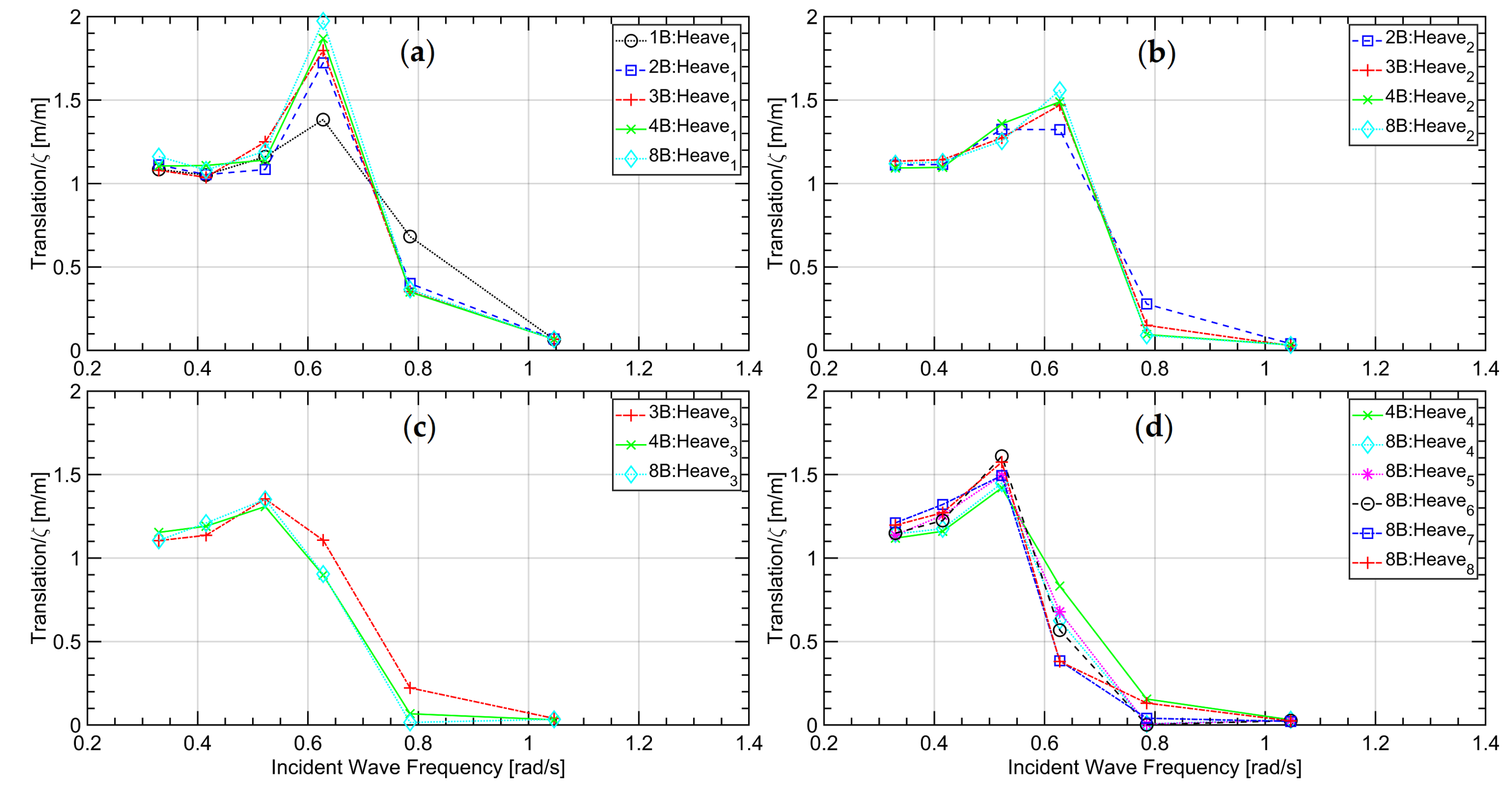
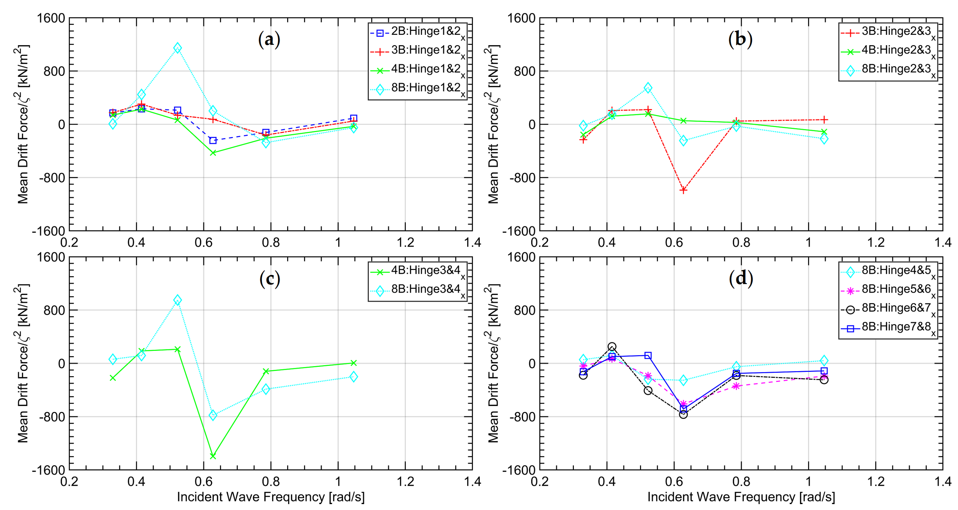
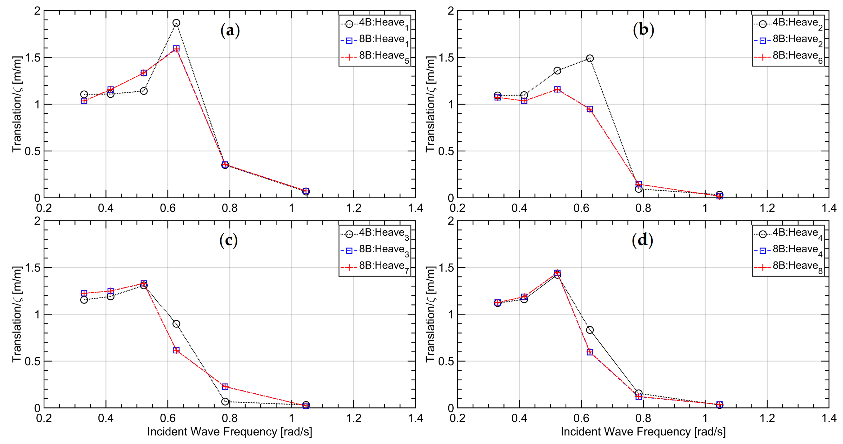
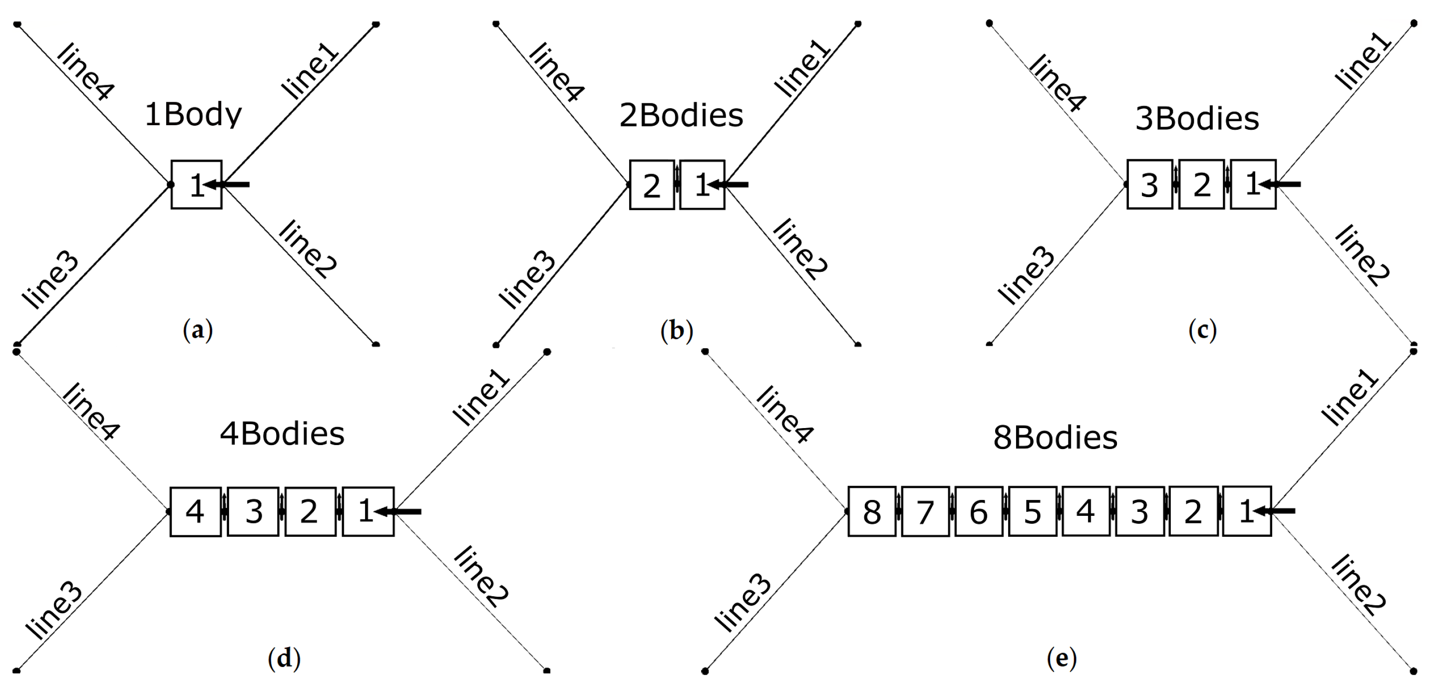
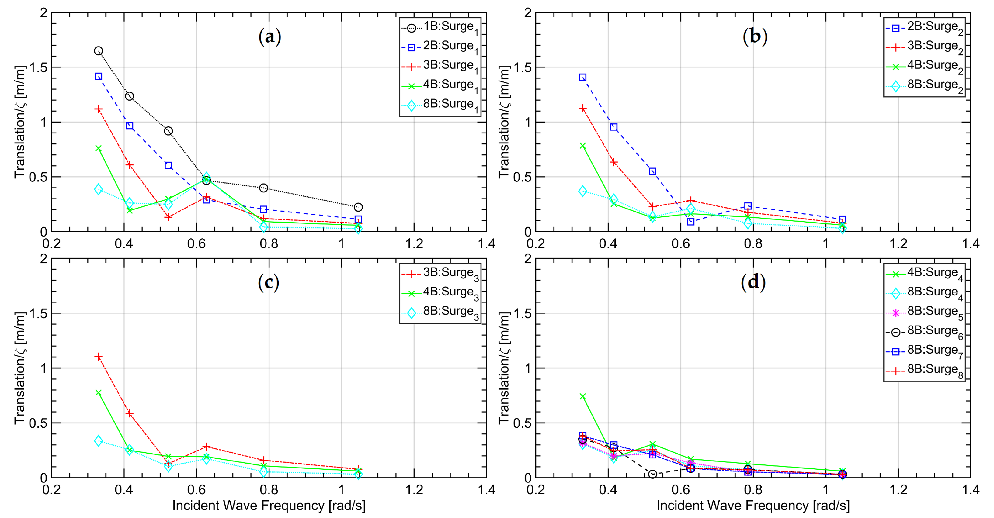
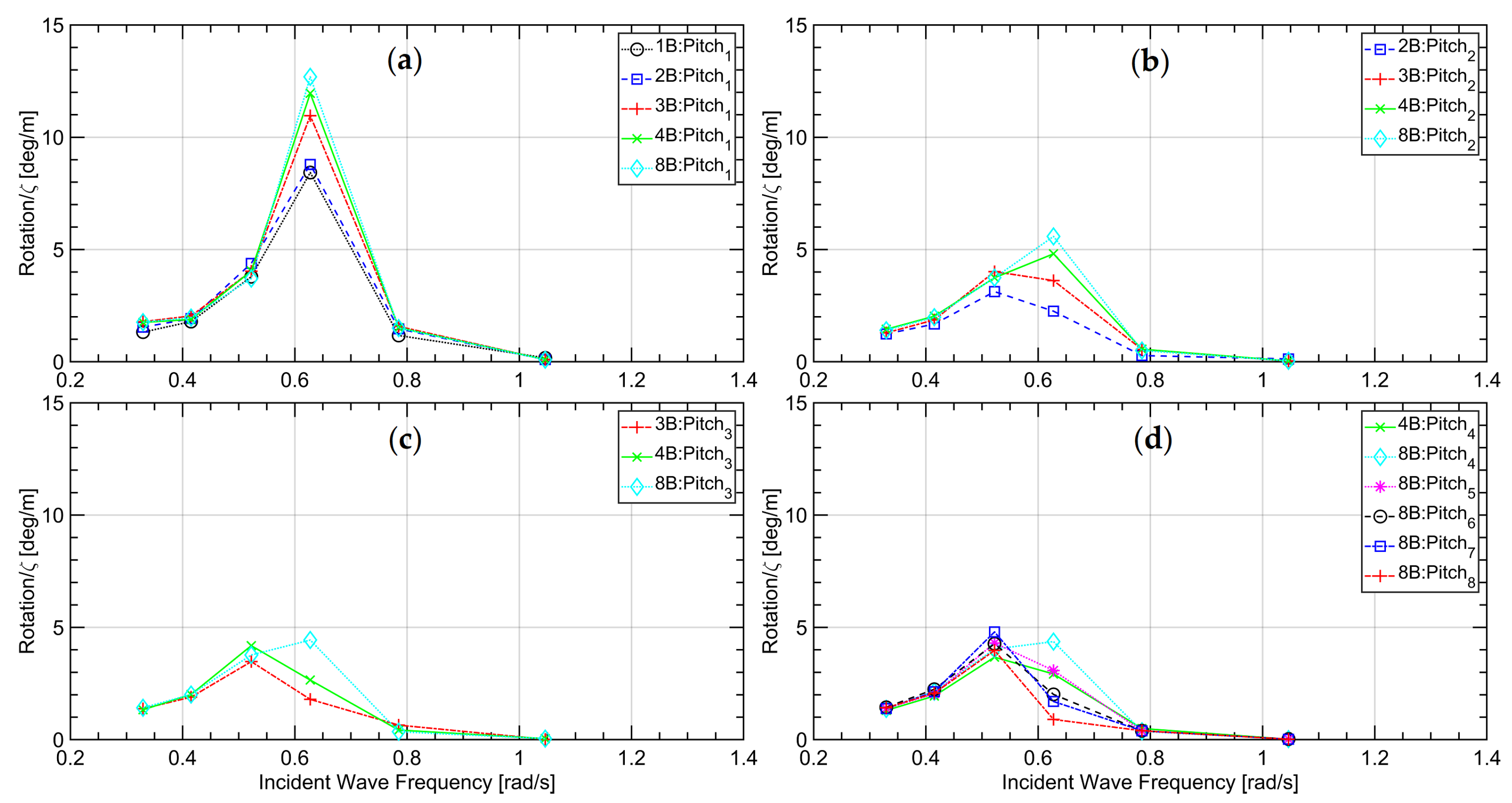
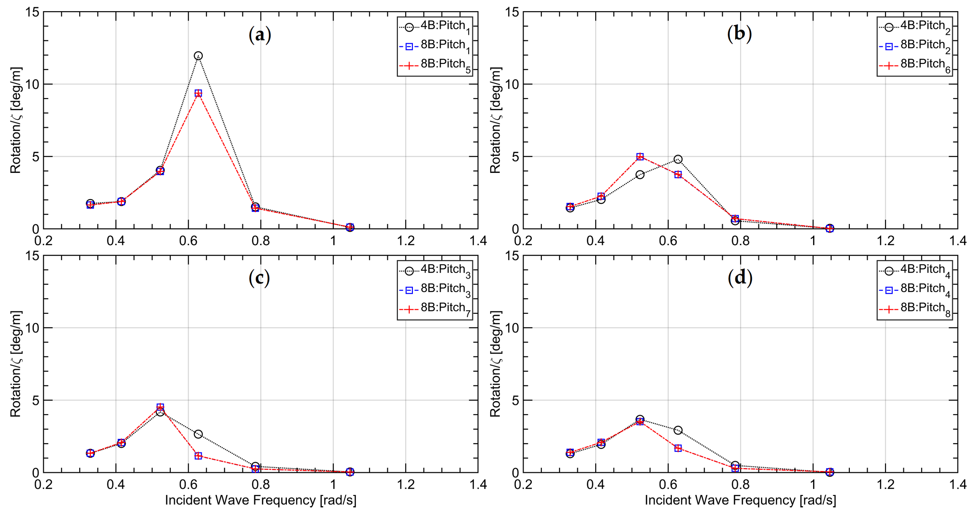
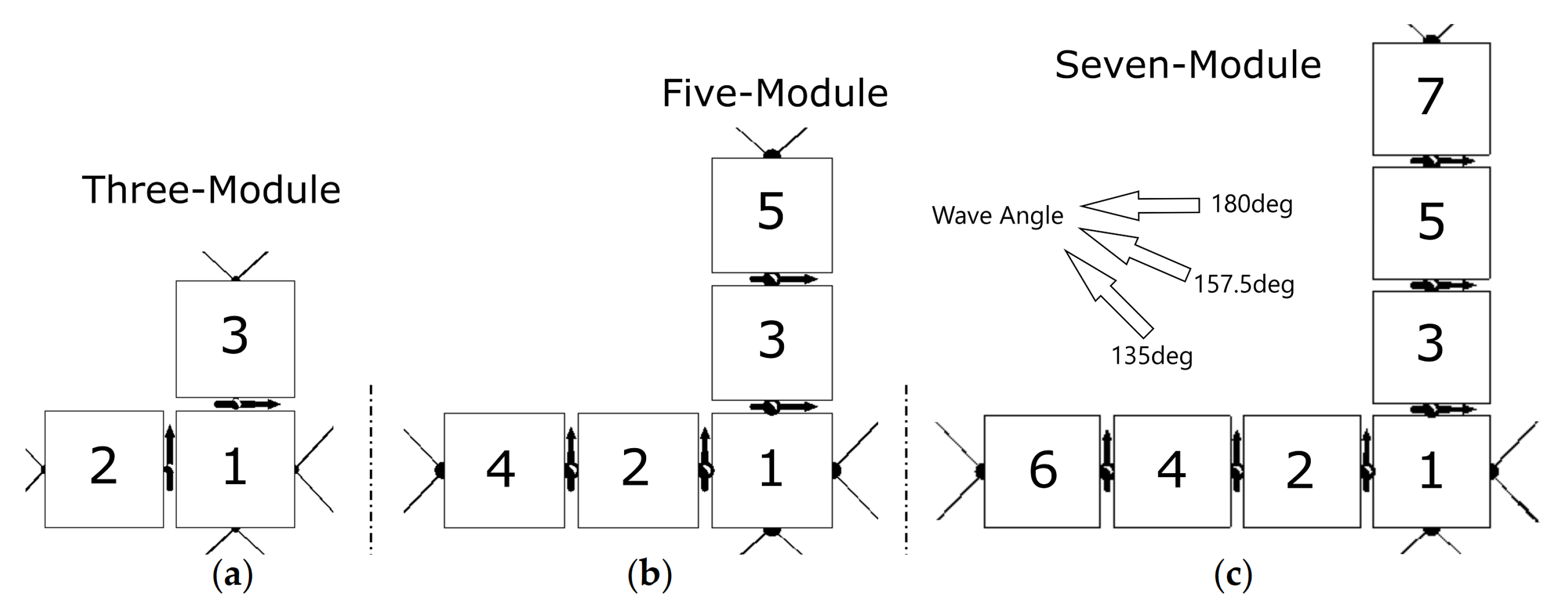
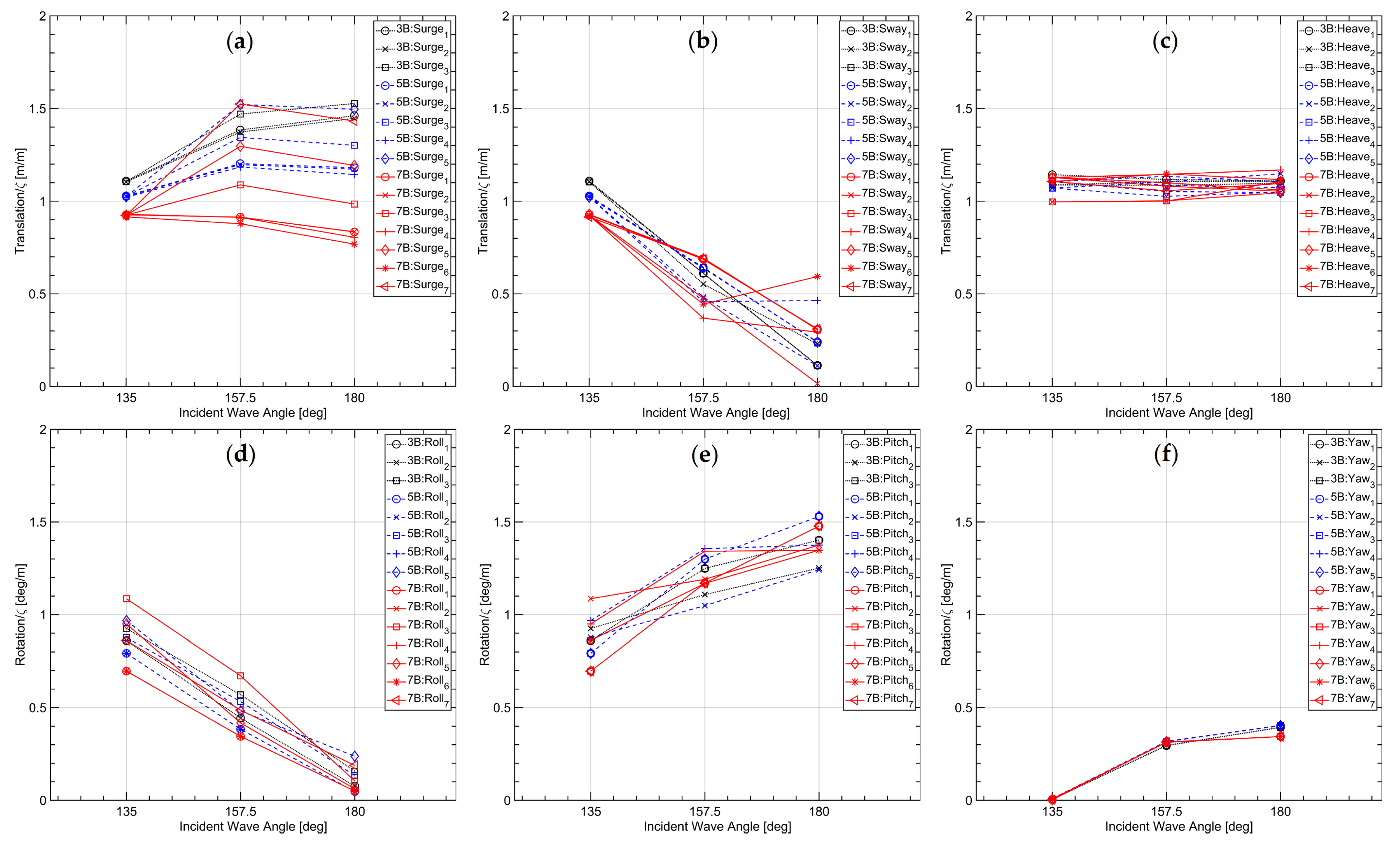
4.2. Sensitivity to the Number of Modules

We considered the chain configuration to study the sensitivity of the number of modules of a hinged multibody offshore platform. We tested five cases under head sea conditions, that is, in waves of 180 heading angle. Case 1 consisted of only one module; case 2, of two modules; case 3, of three modules; case 4, of four modules; and case 5, of eight modules. Figure 5 depicts their layouts. Four symmetrically arranged mooring lines positioned the configurations. Mooring lines 1 and 2 were attached to the first module and mooring lines 3 and 4 to the last module. The axis of the hinge joints proceeded parallel to the y-axis, so that only rotational motion in pitch was possible.
Figure 6, Figure 7 and Figure 8 plot response amplitude operators (RAOs) of surge, heave, and pitch motions, respectively, of the modules for each of these cases, where head waves in six wave frequencies of 0.330, 0.415, 0.552, 0.628, 0.785 and 1.046 rad/s were considered. As seen, differently colored straight lines connect the computed amplitudes, here given as values normalized against wave amplitude, ζ . The legend in the upper right corner of each graph in these figures marks the respective motion responses. For example, symbol 3B:Heave 2 identifies the second module’s heave amplitude of the three-module configuration.
We see that at most wave frequencies, although the floating configurations consisted of a different number of modules, their hydrodynamic characteristics were similar. For surge motions, their amplitudes decreased with increasing wave frequencies except in resonance conditions. With an increase of the number of modules, the associated motion responses in surge were suppressed. For heave and pitch motions, the deviations between cases consisting of a different number of modules occurred near their natural frequency of 0.6 rad/s. Contrary to surge motions, with an increase of the number of modules, the associated heave and pitch motions were activated. In general, the hydrodynamic response of the first module that encounters the incident waves was largest; the hydrodynamic response of the second module was somewhat less than that of the first module, and so on. The associated relative motions between the first two modules were largest. Hydrodynamic characteristics of the modules attached behind the fourth module hardly changed.
Regarding tensions in mooring lines and horizontal loads in hinge joints, we see that second-order horizontal wave-induced drift motions governed these forces. Figure 9 presents an exemplary time series of mooring line tension, where t is time and T is wave period. As seen, the resulting smaller wave-induced oscillating first-order tensile force is superimposed on the lager second-order mean drift tensile force.
Figure 10 presents the results of first-order tension amplitude of mooring line versus wave frequency; Figure 11, the associated results of second-order mean mooring tension; Figure 12, the first-order hinge force amplitude in horizontal direction; Figure 13, the first-order hinge force amplitude in vertical direction; Figure 14, the associated second-order mean hinge forces in horizontal direction; Figure 15, the associated second-order mean hinge forces in vertical direction. All first-order line tensions and hinge forces in Figure 10, Figure 12 and Figure 13 are plotted as values normalized against wave amplitude, ζ ; the second-order line tensions and hinge forces in Figure 11, Figure 14 and Figure 15, as values normalized against wave amplitude squared, ζ 2 . The legend in the upper right corner of each graph identifies the respective responses. For example, symbol 2B:Line3 identifies the tensile force in mooring line 3 of the two-module configuration, or symbol 4B:Hinge2&3 identifies the force acting at the hinge connecting modules 2 and 3 of the four-module configuration.
As seen in Figure 10, maxima of first-order mooring line tension occurred at the lowest wave frequency for nearly all the chain configurations. An exception were the tension in lines 1 and 2 (see Figure 5) for the configuration consisting of three, four and eight modules. For the configuration consisting of more than two floating modules, strong nonlinearities affected the tensile forces in mooring lines 1 and 2 as these frequencies were near the configurations’ natural frequencies, evidenced by higher first-order tensile forces. There strong nonlinearitites were dominated by the nonlinear responses in surge motions, as plotted in Figure 6, where local peak values were also observed for the configurations consisting of more than two floating modules. These first-order tensions were about an order of magnitude smaller than the corresponding second-order mean tensile forces plotted in Figure 11, even at resonance frequencies, indicating that second-order mean forces had a dominant influence on mooring tensions, which meant that the associated low-frequency horizontal wave-induced drift motions governed mooring system designs. With an increase of the number of floating modules for the chain configuration, second-order mean tensions became larger and more dominant, whereas first-order tensions decreased.
From Figure 12 and Figure 13, we see that maximum first-order horizontal and vertical forces acting on the articulated hinge joints occurred around the configurations’ natural frequencies. Horizontal hinge forces were largest between modules 1 and 2, and vertical hinge forces were largest between modules 2 and 3. In general, the horizontal hinge forces maxima exceeded the vertical hinge force maxima by an order of magnitude, and the functional relationships of horizontal hinge forces were more complicated than those of vertical hinge forces. Indeed, the vertical hinge forces were nearly ignorable at most wave frequencies. For the chain configuration consisting of eight modules, except for the first two hinge joints, the maxima of the first-order horizontal hinge forces occurred at lower wave frequencies.
Recall that Figure 14 and Figure 15 present the associated second-order mean hinge forces as values normalized against wave amplitude squared. The results indicated that, especially for cases of higher waves at frequencies near the floating module’s natural frequencies, second-order mean hinge forces may attain high magnitudes that need to be considered when designing such offshore multibody systems.

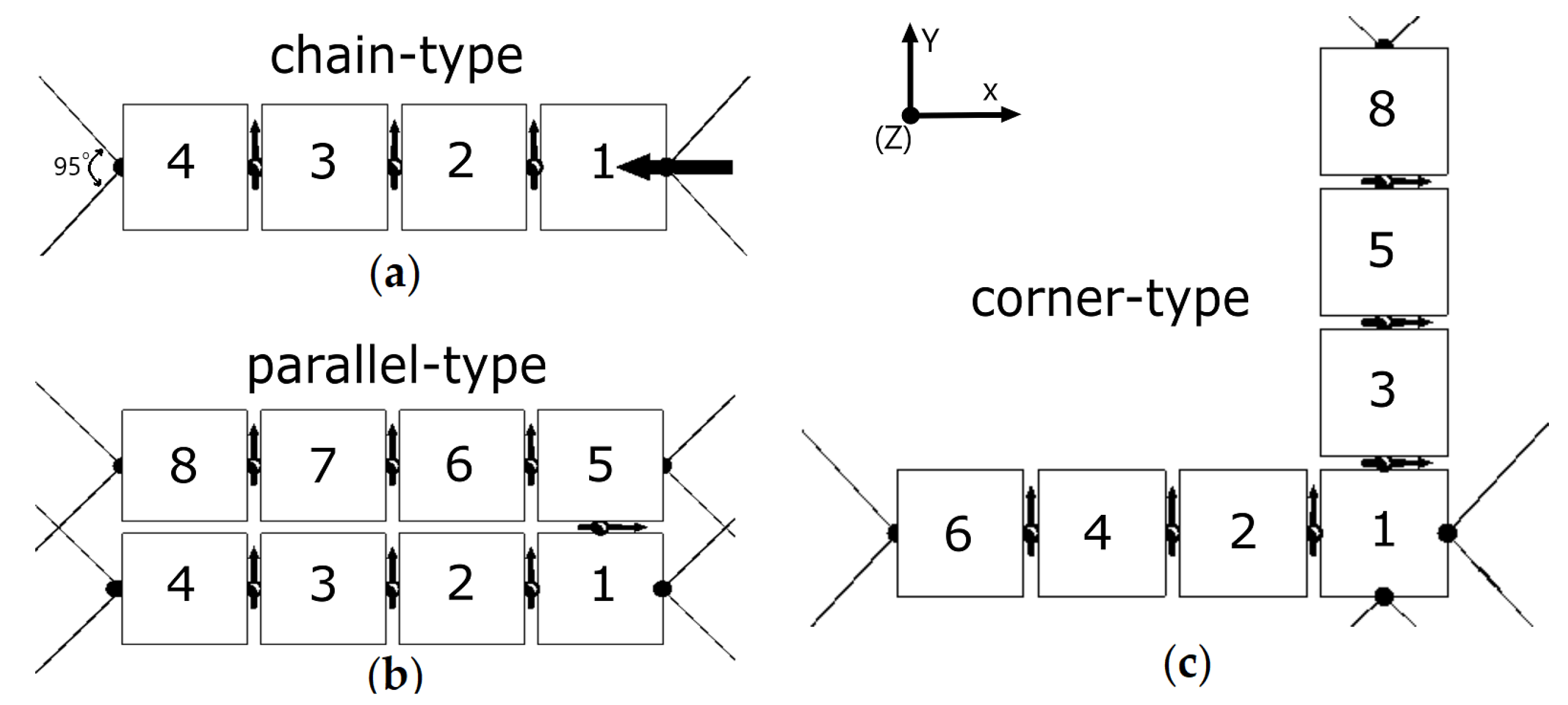
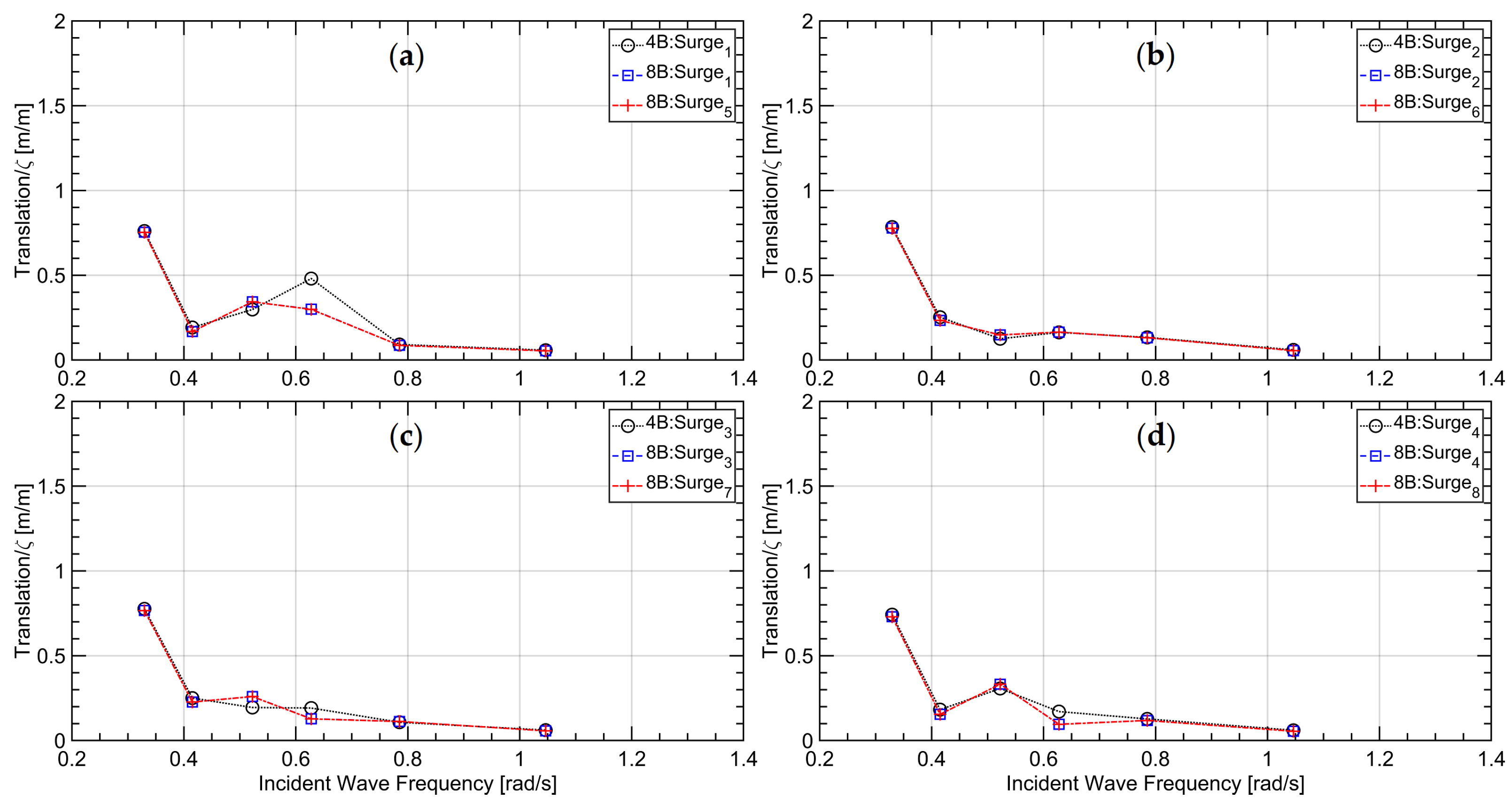
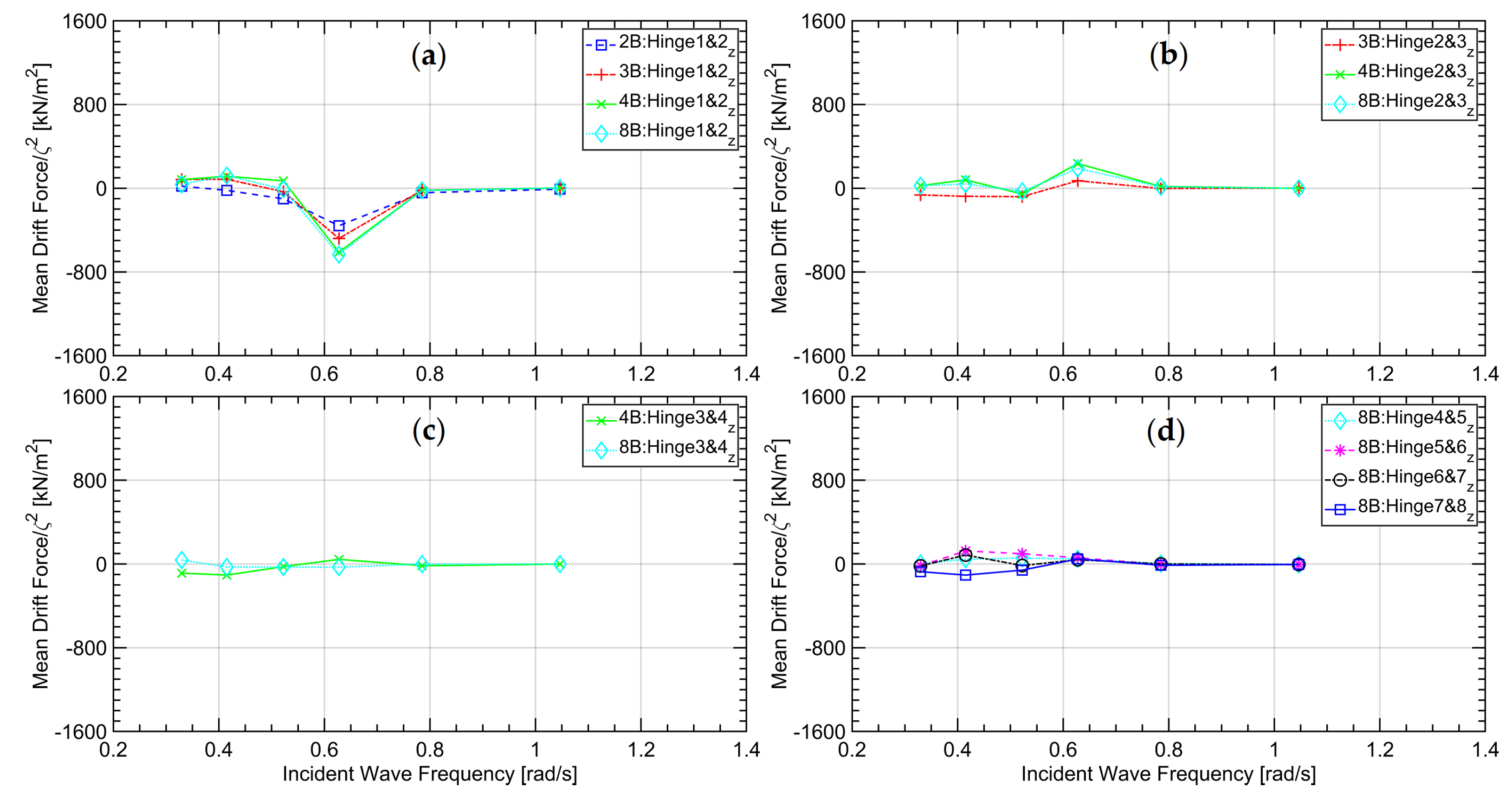
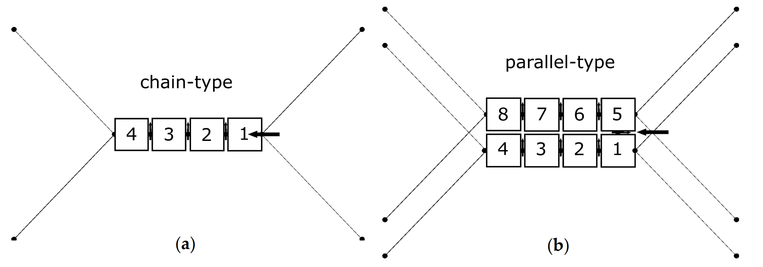
4.3. Sensitivity to Module Arrangement

Apart from the number of floating modules, another aspect we considered was the module arrangement. We considered two configurations, namely, the chain configuration and the parallel configuration, consisting of four and eight modules, respectively. Figure 16 depicts their layouts and the symmetrically arranged mooring lines to position the configurations. Due to the limitation of the adopted numerical model, the configuration connected in a closed loop was not possible and, therefore, the parallel configuration was formed by hinging only modules 1 and 5 between the two chain types.
Figure 17, Figure 18 and Figure 19 plot the RAOs of surge, heave, and pitch motions, respectively, of the modules for the chain configuration and the parallel configuration. Differently colored straight lines connect the computed amplitudes, here given as values normalized against wave amplitude, ζ . The legend in the upper right corner of each graph in these figures marks the respective motion responses. For example, symbol 4B:Heave 2 identifies the second module’s heave amplitude of the four-module chain configuration.
We see that at most wave frequencies, although the two configurations differed, their hydrodynamic characteristics were similar. Similar to the chain configurations investigated in Section 4.2 above, deviations between the chain configuration and the parallel configuration considered here occurred only near their natural frequencies of 0.6 rad/s. Of primary interest was that the parallel arrangement of the modules suppressed the hydrodynamic responses compared to the chain arrangement. Considering also the results from Section 4.2, we concluded that additional modules attached behind or sideways of an existing floating platform configuration suppressed its hydrodynamic motion responses.

4.4. Sensitivity to Incident Wave Angle

To investigate the hydrodynamic sensitivity of different incident wave angles, we considered three corner configurations consisting of three, five, and seven modules. Figure 20 depicts their layouts. To position the configurations, mooring lines were attached to the modules as shown in this figure. As we selected symmetric arrangements of the floating modules, we considered only the three wave incident angles of 135 , 157 . 5 , and 180 . As thees floating modules were targeted to situate nearshore, and incident wave only coming from the offshore side were considered. The considered regular wave had a frequency of 0.415 rad/s, with a relatively long wave length and a small wave amplitude.
Figure 21 plots the resulting six degrees-of-freedom normalized motion amplitudes of the three tested cases. Again, differently colored straight lines connect the computed amplitudes given as values normalized against wave amplitude, ζ . The legend in the upper right corner of each graph in these figures marks the respective motion responses. For example, symbol 5B:Sway 3 identifies the third module’s sway amplitude of the five-module case.
In general, the motion responses were similar although the floating configurations consisted of a different number of modules. Only the translational motions in the horizontal directions, i.e., surge and sway were sensitive to the incident wave angle; the associated translational motions in the vertical direction, i.e., heave remained almost constant. Of the rotational motions, pitch dominated the associated hydrodynamic responses. This was due to the restrictions of the hinge joints. All hydrodynamic responses tended to be suppressed when more modules were attached. The most critical situation occurred at the incident wave angle of 180 , which was the case when pitch motions were largest.

5. Concluding Remarks

We examined the hydrodynamic sensitivity of moored and articulated multibody offshore platforms consisting of a number of standard floating modules. The studied platforms include three separate configurations consisting of different numbers of floating module, subject to regular waves over a range of frequencies or to a regular wave at different incident angles. We relied on a potential-flow theory based approach to predict the configurations’ motion and load responses, accounting for hydrodynamic interactions between neighboring modules and restrictions imposed by articulated connections.
Results showed that at most wave frequencies, although the floating configurations consisted of a different number of modules, their hydrodynamic characteristics were similar. In general, the hydrodynamic response of the first module was largest as it encountered the unaltered incident waves; the hydrodynamic response of the second module was somewhat less than the response of the first module, and so on. The associated relative motions were largest between the first two modules. Hydrodynamic response characteristics of the modules attached behind the fourth module hardly changed.
Wave-induced second-order drift forces had a dominant influence on the mooring systems. Especially at wave frequencies close to the floating module’s natural motion frequencies, the resulting second-order mean line tensions greatly exceeded those of the oscillating first-order line tensions. Thus, the associated low-frequency horizontal motions of these multibody hinged offshore platforms governed mooring system designs. Similar phenomena were also observed regarding the forces acting on the hinge joints.
For floating platforms of different configurations, the deviations of hydrodynamic responses occurred near their natural frequencies. Attaching additional modules behind or sideways of an existing floating structure suppressed its hydrodynamic responses. Only translational motions were sensitive to the incident wave angle; the associated translational motions in the vertical direction remained almost constant.
The aim of this paper was to present hydrodynamic characteristics of various generalized configurations of MFS, as these characteristics may be useful to establish a basis for the design of more complex concepts. To begin with, the limitation of the numerical model we adopted did not allow considering floating modules connected in closed loops. Simulating articulated bodies in a closed loop was beyond the scope of this study although such simulations could have been performed, for instance, via extending the newly-developed solver rigidBodyDynamics in OpenFOAM, using the forward-dynamics algorithm from Featherstone [31]. Thus, it was not feasible to consider an articulated multibody system in a closed loop. Another limitation was that the adopted numerical model could not provide sufficiently accurate results for situations where viscous and nonlinear free-surface effects were prevalent, caused by the flow in gaps between adjacent modules, especially under resonance conditions with green water on the decks of the modules. To assess the hydrodynamic performance of these configurations in extreme sea states, a fully nonlinear potential-flow solver or higher-fidelity approaches would have been required.

Author Contributions

Conceptualization, C.J., O.e.M. and T.E.S.; methodology, C.J. and O.e.M.; software, C.J.; validation, C.J.; formal analysis, C.J.; investigation, C.J.; writing—original draft preparation, C.J.; writing—review and editing, O.e.M. and T.E.S.; supervision, O.e.M.; project administration, O.e.M. All authors have read and agreed to the published version of the manuscript.

Funding

This research was funded by European Union’s Horizon 2020 Research and Innovation Program under grant agreement No. 774253.

Institutional Review Board Statement

Not applicable.

Informed Consent Statement

Not applicable.

Data Availability Statement

Not applicable.

Acknowledgments

We thank all partners of Space@Sea project, specifically Cornel Thill and Raghu Sri Paravastu from Delft University of Technology for performing the experimental model tests.

Conflicts of Interest

The authors declare no conflict of interest.

References

  1. Flikkema, M.; Waals, O. Space@ Sea the floating solution. Front. Mar. Sci. 2019, 6, 553. [Google Scholar] [CrossRef]
  2. Wan, L.; Han, M.; Jin, J.; Zhang, C.; Magee, A.R.; Hellan, Ø.; Wang, C.M. Global dynamic response analysis of oil storage tank in finite water depth: Focusing on fender mooring system parameter design. Ocean Eng. 2018, 148, 247–262. [Google Scholar] [CrossRef]
  3. Suzuki, H. Safety target of very large floating structure used as a floating airport. Mar. Struct. 2001, 14, 103–113. [Google Scholar] [CrossRef]
  4. Wang, C.; Tay, Z. Very large floating structures: Applications, research and development. Procedia Eng. 2011, 14, 62–72. [Google Scholar] [CrossRef] [Green Version]
  5. Olsen, T.O. Fish farming in floating structures. In WCFS2019; Springer: Berlin/Heidelberg, Germany, 2020; pp. 191–208. [Google Scholar]
  6. Liu, H.; Kumar, A.; Reindl, T. The dawn of floating solar—Technology, benefits, and challenges. In WCFS2019; Springer: Berlin/Heidelberg, Germany, 2020; pp. 373–383. [Google Scholar]
  7. Lamas-Pardo, M.; Iglesias, G.; Carral, L. A review of very large floating structures (VLFS) for coastal and offshore uses. Ocean Eng. 2015, 109, 677–690. [Google Scholar] [CrossRef]
  8. Suzuki, H.; Riggs, H.; Fujikubo, M.; Shugar, T.; Seto, H.; Yasuzawa, Y.; Bhattacharya, B.; Hudson, D.; Shin, H. Very large floating structures. In Proceedings of the International Conference on Offshore Mechanics and Arctic Engineering, San Diego, CA, USA, 10–15 June 2007; Volume 42681, pp. 597–608. [Google Scholar]
  9. Wang, G.; Goldfeld, Y.; Drimer, N. Expanding coastal cities–Proof of feasibility for modular floating structures (MFS). J. Clean. Prod. 2019, 222, 520–538. [Google Scholar] [CrossRef]
  10. Ren, N.; Zhang, C.; Magee, A.R.; Hellan, Ø.; Dai, J.; Ang, K.K. Hydrodynamic analysis of a modular multi-purpose floating structure system with different outermost connector types. Ocean Eng. 2019, 176, 158–168. [Google Scholar] [CrossRef]
  11. Drummen, I.; Olbert, G. Conceptual design of a modular floating multi-purpose island. Front. Mar. Sci. 2021, 8, 86. [Google Scholar] [CrossRef]
  12. Riggs, H.; Ertekin, R. Approximate methods for dynamic response of multi-module floating structures. Mar. Struct. 1993, 6, 117–141. [Google Scholar] [CrossRef]
  13. Gao, R.; Tay, Z.; Wang, C.; Koh, C. Hydroelastic response of very large floating structure with a flexible line connection. Ocean Eng. 2011, 38, 1957–1966. [Google Scholar] [CrossRef]
  14. Fu, S.; Moan, T.; Chen, X.; Cui, W. Hydroelastic analysis of flexible floating interconnected structures. Ocean Eng. 2007, 34, 1516–1531. [Google Scholar] [CrossRef]
  15. Michailides, C.; Loukogeorgaki, E.; Angelides, D.C. Response analysis and optimum configuration of a modular floating structure with flexible connectors. Appl. Ocean Res. 2013, 43, 112–130. [Google Scholar] [CrossRef]
  16. Wang, C.M.; Riyansyah, M.; Choo, Y.S. Reducing hydroelastic response of interconnected floating beams using semi-rigid connections. In Proceedings of the International Conference on Offshore Mechanics and Arctic Engineering, Honolulu, HI, USA, 31 May–5 June 2009; Volume 43444, pp. 1419–1425. [Google Scholar]
  17. Xu, D.L.; Zhang, H.C.; Xia, S.Y.; Lu, C.; Qi, E.R.; Tian, C.; Wu, Y.S. Nonlinear dynamic characteristics of a multi-module floating airport with rigid-flexible connections. J. Hydrodyn. 2018, 30, 815–827. [Google Scholar] [CrossRef]
  18. Zhang, Y.; Liu, H. Methodology for the assessment and optimization of connection parameter combinations for modular floating structures. J. Offshore Mech. Arct. Eng. 2021, 143, 021301. [Google Scholar] [CrossRef]
  19. Woernle, C. Mehrkörpersysteme; Springer: Berlin/Heidelberg, Germany, 2011. [Google Scholar]
  20. Newman, J. Wave effects on hinged bodies. In Part II—Hinge Loads. 1997. Available online: http://www.wamit.com/publications.htm (accessed on 15 August 2021).
  21. Ghesmi, M.; von Graefe, A.; Shigunov, V.; Friedhoff, B.; el Moctar, O. Comparison and validation of numerical methods to assess hydrodynamic loads on mechanical coupling of multiple bodies. Ship Technol. Res. 2019, 66, 9–21. [Google Scholar] [CrossRef]
  22. Rogne, Ø.Y. Numerical and Experimental Investigation of a Hinged 5-Body Wave Energy Converter. Ph.D. Thesis, Norges Teknisk-Naturvitenskapelige Universitet, Fakultet for Ingeniørvitenskap og Teknologi, Institutt for Marin Teknikk, Trondheim, Norway, 2014. [Google Scholar]
  23. Diamantoulaki, I.; Angelides, D.C. Analysis of performance of hinged floating breakwaters. Eng. Struct. 2010, 32, 2407–2423. [Google Scholar] [CrossRef]
  24. Zhu, H.; Sueyoshi, M.; Hu, C.; Yoshida, S. Modelling and attitude control of a shrouded floating offshore wind turbine with hinged structure in extreme conditions. In Proceedings of the 2017 IEEE 6th International Conference on Renewable Energy Research and Applications (ICRERA), San Diego, CA, USA, 5–8 November 2017; pp. 762–767. [Google Scholar]
  25. ANSYS, A. AQWA User’s Manual Release 17.0; ANSYS Inc.: Canonsburg, PA, USA, 2016. [Google Scholar]
  26. Newman, J.N. Algorithms for the free-surface Green function. J. Eng. Math. 1985, 19, 57–67. [Google Scholar] [CrossRef]
  27. Clark, P.; Malenica, Š.; Molin, B. An heuristic approach to wave drift damping. Appl. Ocean Res. 1993, 15, 53–55. [Google Scholar] [CrossRef]
  28. Thill, C.; Sri Paravastu, R. Model Tests Report D4.3 Space@Sea; Technical Report; Delft University of Technology: Delft, The Netherlands, 2018. [Google Scholar]
  29. Flikkema, M.; Breuls, M.; Jak, R.; de Ruijter, R.; Drummen, I.; Jordaens, A.; Adam, F.; Czapiewska, K.; Lin, F.Y.; Schott, D.; et al. Floating Island Development and Deployment Roadmap; Technical Report; Space@Sea: Wageningen, The Netherlands, 2021. [Google Scholar]
  30. Seithe, G.; el Moctar, O. Wave-Induced Motions of Moored and Coupled Multi-Body Offshore Structures. In Proceedings of the 11th International Workshop on Ship and Marine Hydrodynamic, Hamburg, Germany, 22–25 September 2019; pp. 85–97. [Google Scholar]
  31. Featherstone, R. Rigid Body Dynamics Algorithms; Springer: Berlin/Heidelberg, Germany, 2014. [Google Scholar]
Figure 1. Layout of the multi-use floating island of Energyhub@Sea concept adopted from [29]. Reproduced with permission from Maarten Flikkema, Floating Island Development and Deployment Roadmap; published by Space@Sea project, 2021.
Jmse 09 01028 g001
Figure 2. Illustrative representation of the numerical setup, including hinged joint and mooring lines.
Jmse 09 01028 g002
Figure 3. Schematic representation of the considered floating configurations: (a) the chain configurations; (b) the parallel configuration; (c) and the corner configuration.
Jmse 09 01028 g003
Figure 4. Computed and measured motion responses in (a) surge, (b) heave and (c) pitch for one module in head waves.
Jmse 09 01028 g004
Figure 5. Layouts of the five test cases of the chain configuration for studying the sensitivity to the number of modules: (a) one-module case; (b) two-module case; (c) three-module case; (d) four-module case; (e) eight-module case.
Jmse 09 01028 g005
Figure 6. RAOs of surge response of the five test cases for the chain configuration, where nB denotes the configuration with n bodies; subscript n, the corresponding n-th body’s motion response: (a) the 1st module; (b) the 2nd module; (c) the 3rd module; (d) the 4th–8th modules.
Jmse 09 01028 g006
Figure 7. RAOs of heave response of the five test cases for the chain configuration, where nB denotes the configuration with n bodies; subscript n, the corresponding n-th body’s motion response: (a) the 1st module; (b) the 2nd module; (c) the 3rd module; (d) the 4th–8th modules.
Jmse 09 01028 g007
Figure 8. RAOs of pitch response of the five test cases for the chain configuration, where nB denotes the configuration with n bodies; subscript n, the corresponding n-th body’s motion response: (a) the 1st module; (b) the 2nd module; (c) the 3rd module; (d) the 4th–8th modules.
Jmse 09 01028 g008
Figure 9. Sample time series of mooring tensions of the one-module case for the chain configuration.
Jmse 09 01028 g009
Figure 10. First-order mooring tension amplitudes of the five test cases for the chain configuration, where nB denotes the configuration with n bodies; subscript n, the corresponding n-th mooring line: (a) line 1 and line 2; (b) line 3 and line 4.
Jmse 09 01028 g010
Figure 11. Second-order mean mooring tensions of the five test cases for the chain configuration, where nB denotes the configuration with n bodies; subscript n, the corresponding n-th mooring line: (a) line 1 and line 2; (b) line 3 and line 4.
Jmse 09 01028 g011
Figure 12. First-order hinge forces in horizontal direction of the five test cases for the chain configuration, where nB denotes the configuration with n bodies; m & n , the hinge connecting m-th body and n-th body; subscript x, the hinged forces in x direction: (a) between 1st and 2nd modules; (b) between 2nd and 3rd modules; (c) between 3rd and 4th modules; (d) between 4th and 5th, 5th and 6th, 6th and 7th, 7th and 8th modules.
Jmse 09 01028 g012
Figure 13. First-order hinge forces in vertical direction of the five test cases for the chain configuration, where nB denotes the configuration with n bodies; m & n , the hinge connecting m-th body and n-th body; subscript z, the hinged forces in z direction: (a) between 1st and 2nd modules; (b) between 2nd and 3rd modules; (c) between 3rd and 4th modules; (d) between 4th and 5th, 5th and 6th, 6th and 7th, 7th and 8th modules.
Jmse 09 01028 g013
Figure 14. Second-order mean hinge forces in horizontal direction of the five test cases for the chain configuration, where nB denotes the configuration with n bodies; m & n , the hinge connecting m-th body and n-th body; subscript x, the hinged forces in x direction: (a) between 1st and 2nd modules; (b) between 2nd and 3rd modules; (c) between 3rd and 4th modules; (d) between 4th and 5th, 5th and 6th, 6th and 7th, 7th and 8th modules.
Jmse 09 01028 g014
Figure 15. Second-order hinge forces in vertical direction of the five test cases for the chain configuration, where nB denotes the configuration with n bodies; m & n , the hinge connecting m-th body and n-th body; subscript z, the hinged forces in z direction: (a) between 1st and 2nd modules; (b) between 2nd and 3rd modules; (c) between 3rd and 4th modules; (d) between 4th and 5th, 5th and 6th, 6th and 7th, 7th and 8th modules.
Jmse 09 01028 g015
Figure 16. Layouts of the test cases for studying the sensitivity to module arrangement: (a) the chain configuration; (b) and the parallel configuration.
Jmse 09 01028 g016
Figure 17. RAOs of surge response for studying the sensitivity to module arrangement, where nB denotes the configuration with n bodies; subscript n, the corresponding n-th body’s motion response: (a) the 1st and 5th modules; (b) the 2nd and 6th modules; (c) the 3rd and 7th modules; (d) the 4th and 8th modules.
Jmse 09 01028 g017
Figure 18. RAOs of heave response studying the sensitivity to module arrangement, where nB denotes the configuration with n bodies; subscript n, the corresponding n-th body’s motion response: (a) the 1st and 5th modules; (B) the 2nd and 6th modules; (c) the 3rd and 7th modules; (d) the 4th and 8th modules.
Jmse 09 01028 g018
Figure 19. RAOs of pitch response studying the sensitivity to module arrangement, where nB denotes the configuration with n bodies; subscript n, the corresponding n-th body’s motion response: (a) the 1st and 5th modules; (b) the 2nd and 6th modules; (c) the 3rd and 7th modules; (d) the 4th and 8th modules.
Jmse 09 01028 g019
Figure 20. The three corner configurations considered for studying the sensitivity to incident wave angle: (a) the three-module case; (b) five-module case; (c) and seven-module case.
Jmse 09 01028 g020
Figure 21. Normalized motion response amplitudes in six degrees of freedom vs. incident wave angle in regular waves of frequency 0.415 rad/s, where nB denotes the configuration with n bodies; subscript n, the corresponding n-th body’s motion response: (a) surge; (b) sway; (c) heave; (d) roll; (e) pitch; (f) yaw.
Jmse 09 01028 g021
Table 1. Primary particulars of a floating module (1 center of gravity above keel).
LengthBreadthHeightDraftMassCoG 1 K xx K yy K zz
45 m45 m15 m9 m18,281.9 t8.72 m16.8 m16.8 m18.375 m
Table 2. Properties of the adopted mooring line.
Unstretched LengthStiffnessPretension
161 m64.19 kN/m2337.4 kN
Publisher’s Note: MDPI stays neutral with regard to jurisdictional claims in published maps and institutional affiliations.

