1. Introduction
In 2002, the International Maritime Organization (IMO) approved maneuverability standards that should be applied to all ships that are 100 m in length between the perpendiculars or longer of all rudder and propulsion types, and to chemical tankers, and gas carriers, regardless of their length [
1]. The establishment of these standards accelerated research on accurate estimation of the maneuverability of a ship in the design stage. However, since most fishing vessels are less than 100 m in LBP, the IMO maneuverability standards do not apply [
1]. Therefore, studies on maneuverability are usually conducted only for specific vessels. Studies performed by Yoshimura [
2,
3], Dan [
4], Lee [
5,
6,
7], and Kim [
8] are representative of those that estimate maneuverability in vessels less than 100 m in LBP but are insufficiently compared to studies on merchant ships’ hull form.
Methods for estimating maneuverability in the design stage may utilize model tests, similar/equivalent hull forms from the past, or numerical methods [
9]. The maneuverability of fishing vessels is estimated by adopting an empirical formula that derives results through a simple process rather than a costly and time-consuming model test (despite the high accuracy of those model tests) [
10]. However, the empirical formula currently used is generally derived from the model test results of merchant ship’s hull form with the length of 100 m or longer to which the IMO maneuverability standard is applied. Since several parameters such as
and
—where
stand for the LBP, breadth, and block coefficient of the hull, respectively—are highly correlated with one another during the derivation process, the accuracy of estimation, however, may vary depending on the similarity of hull forms between the target ship and merchant ships [
10,
11].
Fishing vessels have its own hull form characteristics that are somewhat different from those of general merchant ships because they must have the mobility to chase moving fish groups, high volume of fish tanks, and the stability to stay upright. Therefore, when the empirical formula developed for merchant ships’ hull form is applied to fishing vessels without correction, estimation errors may occur due to the different characteristics of hull forms [
10].
Although maritime accidents caused by fishing vessels do not causes enormous natural disasters compared with those caused by large merchant ships, they can still result in enormous casualties as fishing activities require multiple people on board. Regardless of whether the IMO maneuverability standards are applied or not, researchers should continuously conduct studies to estimate the maneuverability of fishing vessels to provide the motion characteristic indices to the ship operators. In addition, it is necessary to develop a simulation program for accident analysis when maritime accidents occur due to maneuverability [
12,
13,
14,
15].
In this context, the authors of this paper previously estimated the maneuverability of trawl fishing vessels’ hull form using Kijima et al. (1990) empirical formula [
16]. To improve estimation accuracy, a modified empirical formula was also derived by adding the hull form parameters of the trawl fishing vessels. In this paper, we use Kijima et al. (1990) empirical formula and our modified empirical formula to perform turning motion and zigzag test simulations, which constitute part of the IMO maneuverability assessment on a training vessel with a trawl fishing vessel’s hull form built in 2020. Then, the validity of the modified empirical formula is determined by comparing the results of the simulation to those from tests conducted on the actual vessel [
17].
2. Mathematical Model
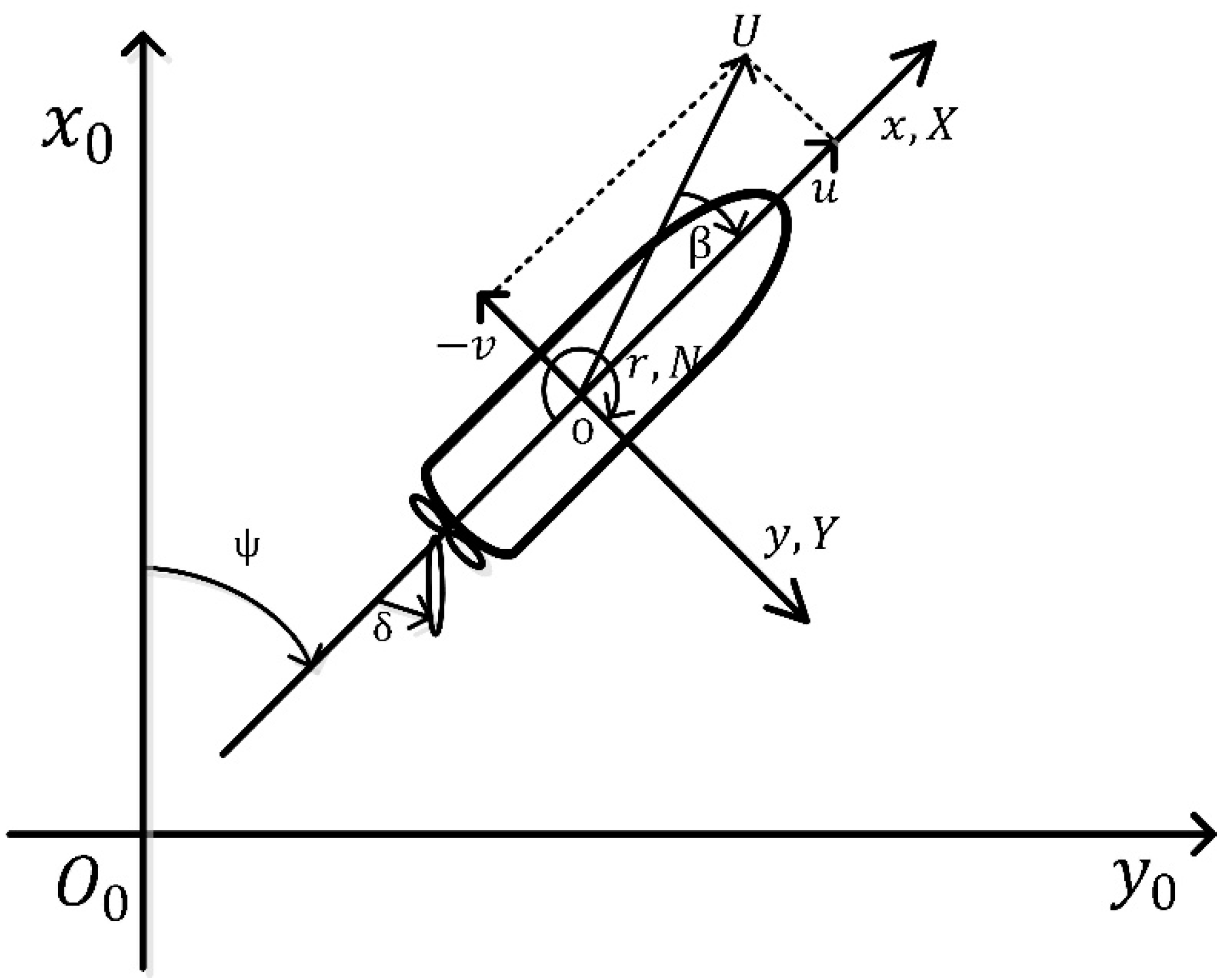
2.1. Coordinate Systems and Equations of Motion
The equations of motion used in this study were derived from the right-handed Cartesian coordinate system in
Figure 1. The term
represents the earth-fixed coordinate system, and the term
represents the hull-fixed coordinate system, in which the mid-ship of the hull is fixed at the point of origin
. Here
is oriented vertically downwards in the
plane, and
is oriented vertically downwards in the
plane.
There are several ways to express the equation of motion for maneuvering, but in Kijima et al. (1990) empirical formula (used as the reference model for this study), the drift angle
and the dimensionless angular velocity
were used to express maneuverability as shown in Equation (1):
Here, ′ (prime) represents a quantity that is rendered dimensionless as shown below.
Kijima et al. (1990) empirical formula was based on the maneuvering modeling group model [
9,
18]. Equation (1) can be expressed as Equation (2) by dividing the external force terms
on the right side into the hull, rudder, and propeller components, respectively. Here, the subscripts H, R, and P denote hull, rudder, and propeller, respectively [
16].
2.1.1. Forces and Moments Acting on the Hull
The forces
and the moment
acting on the hull can be expressed as Equation (3), using the drift angle,
and the dimensionless angular velocity,
[
19].
2.1.2. Forces and Moments from the Propellers
In general, the force generated from the propeller is the forward and backward force,
. If terms
and
are omitted on the assumption that force
and moment
are negligible, it can be expressed as Equation (4) as follows [
16].
2.1.3. Forces and Moments from the Rudder
Forces
and moment
from the rudder are given by Equation (5), where
are the main interaction coefficients acting between the rudder, propeller, and hull, and the normal pressure
has high correlation with the interaction coefficients [
16].
2.2. Kijima et al. (1990) Empirical Formula
Model tests are most likely to minimize the gap between the estimated maneuverability of a ship at the design stage and the actual maneuverability of the constructed ship. However, since fishing vessels relied on the empirical formula rather than model tests, there was a limitation for collecting model test results for fishing vessels to derive an empirical formula tailored to fishing vessels. In light of this, the authors previously conducted a study to modify the empirical formula originally developed for merchant ships’ hull form so that it could be applied to fishing-type vessels as well [
5,
6,
7,
8]. The model empirical formula used for this study was the one proposed by Kijima et al. (1990).
Among numerous empirical formulas developed for merchant ship’s hull form, Kijima et al. (1990) empirical formula was selected because the process of deriving the empirical formula and the specifications of the vessels used in the model tests were clearly disclosed. Since the applicable formulas were divided according to whether the shape of the stern was to be considered or not, a wide range of choices were available [
16,
20,
21]. However, previous studies confirmed that there were slight differences between the hull form of fishing vessels and that of merchant ships. It was also verified by comparing the simulated trajectories of turning motions that including the shape of the stern as an additional consideration to the equation could reduce the accuracy in estimating the maneuverability of fishing vessels’ hull form Therefore, the authors of this study determined that the version of Kijima et al. (1990) empirical formula without considerations for the stern shape is more suitable for estimating the maneuverability of fishing vessels’ hull form.
Table 1 shows the main specifications of the 13 model merchant ships used for the derivation of Kijima et al. (1990) empirical formula on an even keel and under full load conditions. Equation (7) displays the equation for deriving the derivatives acting on the hull and the interaction coefficients acting among the hull, propeller, and rudder.
where k = 2d/L.
Meanwhile, Equation (7) reveals that certain parameters such as
and
—indicating the hull form characteristics—can be highly correlated with one another during the regression analysis on the model test results [
11]. It can also be seen that these parameters can also affect the derivation of derivative values through empirical formulas. The accuracy of results can be improved if such parameters are similar or equivalent to those obtained from the model merchant ships included in the derivation of empirical formulas.
2.3. Modified Empirical Formula
In the process of estimating the maneuverability of a vessel using empirical formulas, the main specifications and hull form characteristics of the vessel may affect the estimation accuracy, as described in
Section 2.2. The authors of this paper have already confirmed in a previous study that the hull form of fishing vessels has unique characteristics that are somewhat different from those of the merchant ships’ hull form [
8,
10]. To estimate the maneuverability of the fishing vessels’ hull form more accurately, a modified empirical formula was derived from Kijima et al. (1990) original empirical formula. This section outlines the process of deriving the modified empirical formula.
2.3.1. Selection of Hull Forms
The hull forms of fishing vessels, not unlike those of merchant ships, vary depending on the fishing work types. Among those, a trawl fishing vessel hull form was selected as the basis for this study for deriving the modified empirical formula for the following reasons [
10].
First, a typical trawl fishing vessel has a larger size than most fishing vessels and carries as many as 50 or more crew members on board; this increases the risk of a large-scale casualty in case of an accident, and thus, we determined the hull form of trawl fishing vessels to be the priority target of research. In addition, it was easier to collect test results at the design stage for trawler hull forms—on traits such as resistance, self-propulsion, and open water tests on propellers, among others—compared to others; these test results are necessary for conducting research to derive a modified empirical formula. Finally, regarding test experiments, the trawler hull form obtained stable results with relatively little influence from external factors; this trait allows for a more reliable comparison with the estimated results using the empirical formulas.
Five training trawl fishing vessels were selected as model fishing vessels for this test. The main specifications of the vessels are shown in
Table 2.
2.3.2. Analysis of Hull form Parameters
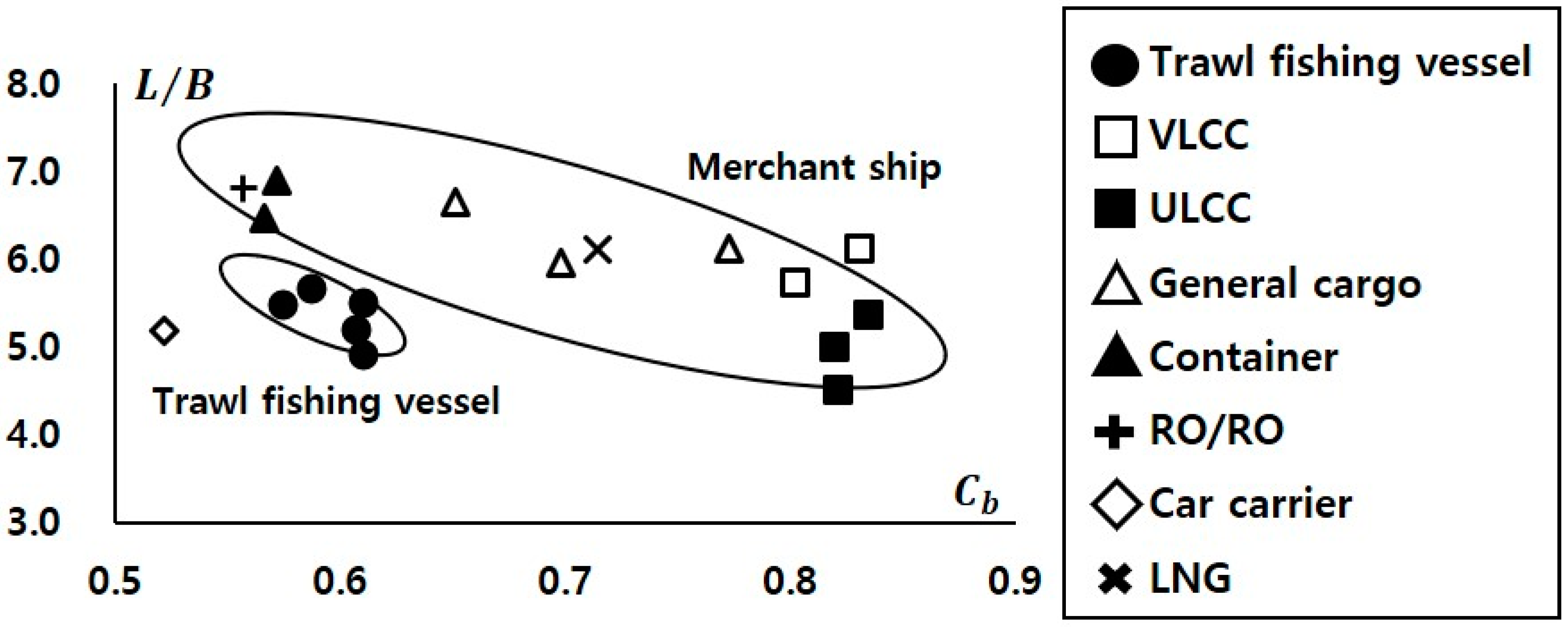
Before deriving maneuvering hydrodynamic derivatives of the model ships (13 model merchant ships, five model trawl fishing vessels), using Kijima et al. (1990) empirical formula,
for the
ratio of the model ships were compared to confirm the difference in characteristics between the hull forms of fishing vessels and merchant ships listed in
Table 1 and
Table 2. Results indicate that the
of the fishing vessels’ hull form, which for mobility to chase fish, was similar to that of fine high-speed slender body ships such as container ships, roll-on/roll-off ships, and car carriers [
10]. In comparison, the
ratio of fishing vessels’ hull form, which for fish storage capacity and stability in the rough sea, resembled that of low-speed full body ships such as very/ultra large crude oil carriers (VLCC/ULCC) [
10] (
Figure 2).
The
and
presented in
Figure 2 are the most representative hull form characteristics that have an important correlation in the model test regression analysis process for deriving empirical expressions. As shown in
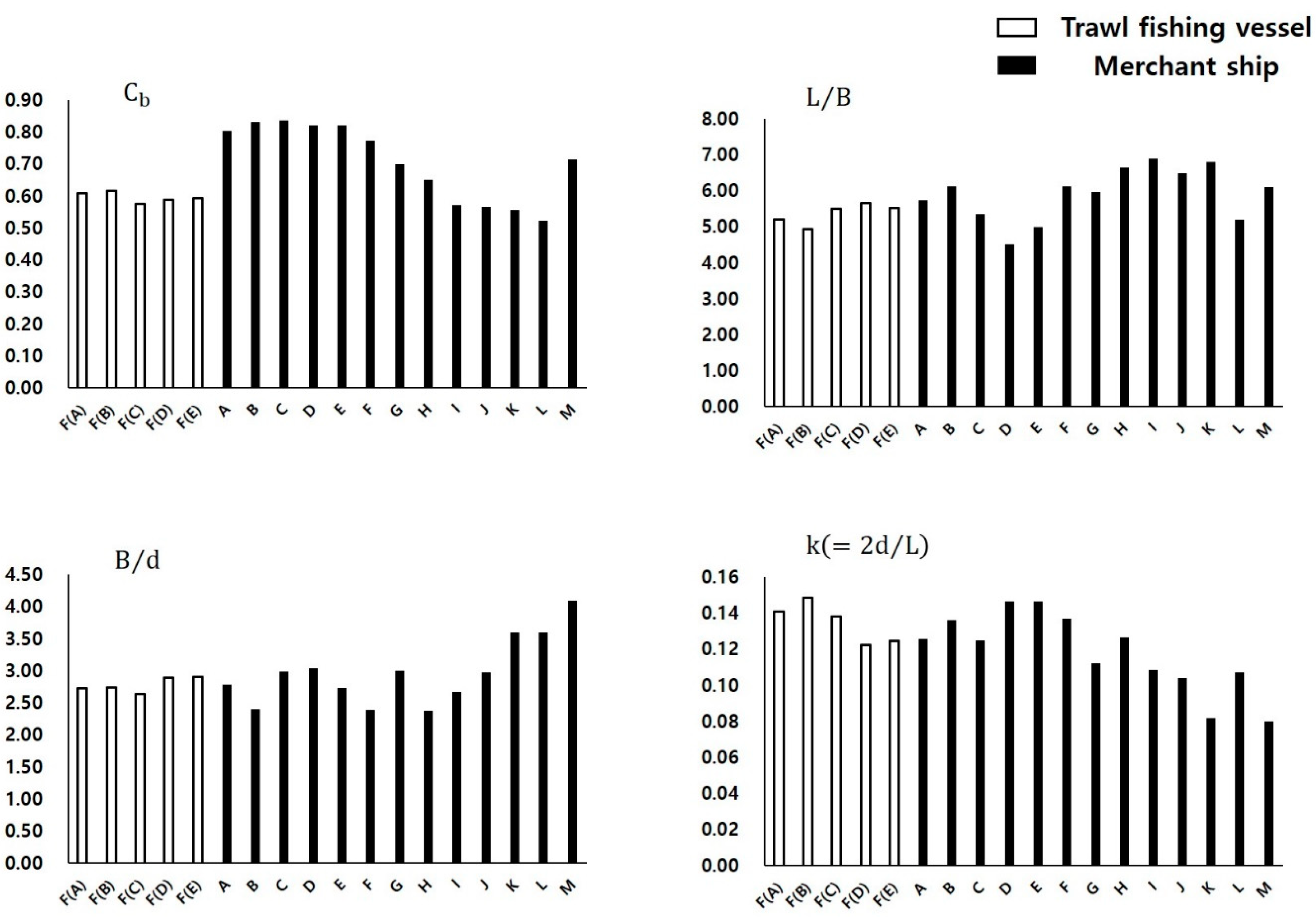
Figure 2, fishing vessels and merchant ships have somewhat different hull form characteristics. Before deriving the modified empirical formula using Kijima et al. (1990), the major hull form parameter values of the model ships were compared, as shown in
Figure 3. First, the
of model trawl fishing vessels resembled that of container ships the most, and their
was similar to that of VLCC, ULCC, and car carriers. In addition, their
was comparable to that of several others, such as VLCC, ULCC, cargo ships, and container ships. Lastly, it was confirmed that their
was similar to that of VLCC, ULCC.
Figure 3 confirmed that the trawl fishing vessel hull form of model fishing vessels has its own characteristics that are different from those of any specific merchant ship. Results confirmed that an estimation error could occur if the empirical formula developed for merchant ships was applied to fishing vessels without modification.
2.3.3. Deriving a Modified Empirical Formula
The most ideal way to develop an empirical formula for estimating the maneuverability of fishing vessels’ hull form at the design stage is to go through a research process similar to the one used to develop the empirical formula for merchant ships. However, most of the data on the maneuverability of fishing vessels are studies on a single target vessel, and data for estimating maneuverability such as model tests are lacking [
22,
23,
24,
25,
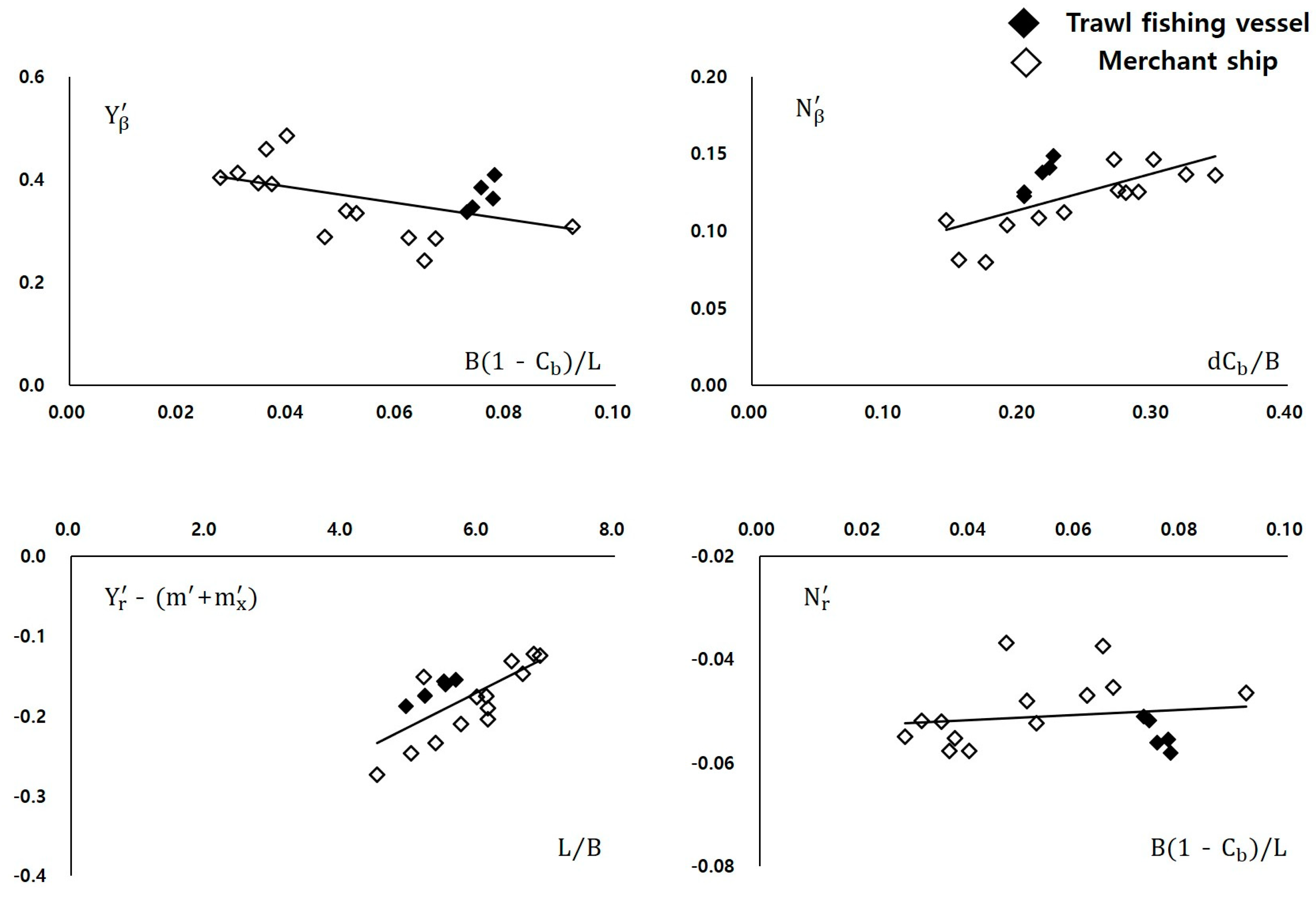
26]. Therefore, this study derived a modified empirical formula by adding the hull form parameters of fishing vessels to Kijima et al. (1990) empirical formula originally developed for merchant ships’ hull form. The derivation process is outlined below [
10], and the modification graph for the linear derivatives is shown in
Figure 4.
Using Kijima et al. (1990) empirical formula in Equation (7), the maneuvering hydrodynamic derivatives of the 18 model ships (13 model merchant ships, five model trawl fishing vessels) listed in
Table 1 and
Table 2 were derived.
In the process of deriving the value of each derivative, all hull form parameters with high correlation with one another were identified.
In the preceding step, we identified those parameters (i) which were correlated with each derivative and (ii) whose tendencies differed between the hull forms of fishing vessels and merchant ships; hereafter, we displayed the correlation of the chosen parameters with the derivatives in graphs.
The error occurring for the model fishing vessels’ hull form was corrected using the average value for the trend line indicated by the graph.
From the results above, a modified empirical formula was derived to improve the estimation of maneuverability for fishing vessels’ hull form; the results are shown in Equation (8). However, the modified empirical formula drew a limited set of hull forms from trawl fishing vessels. Therefore, applying the modified empirical formula to other hull forms of fishing vessels may lead to an estimation error due to differences in hull form characteristics.
2.3.4. Validation of Modified Empirical Formulas
Table 3 and
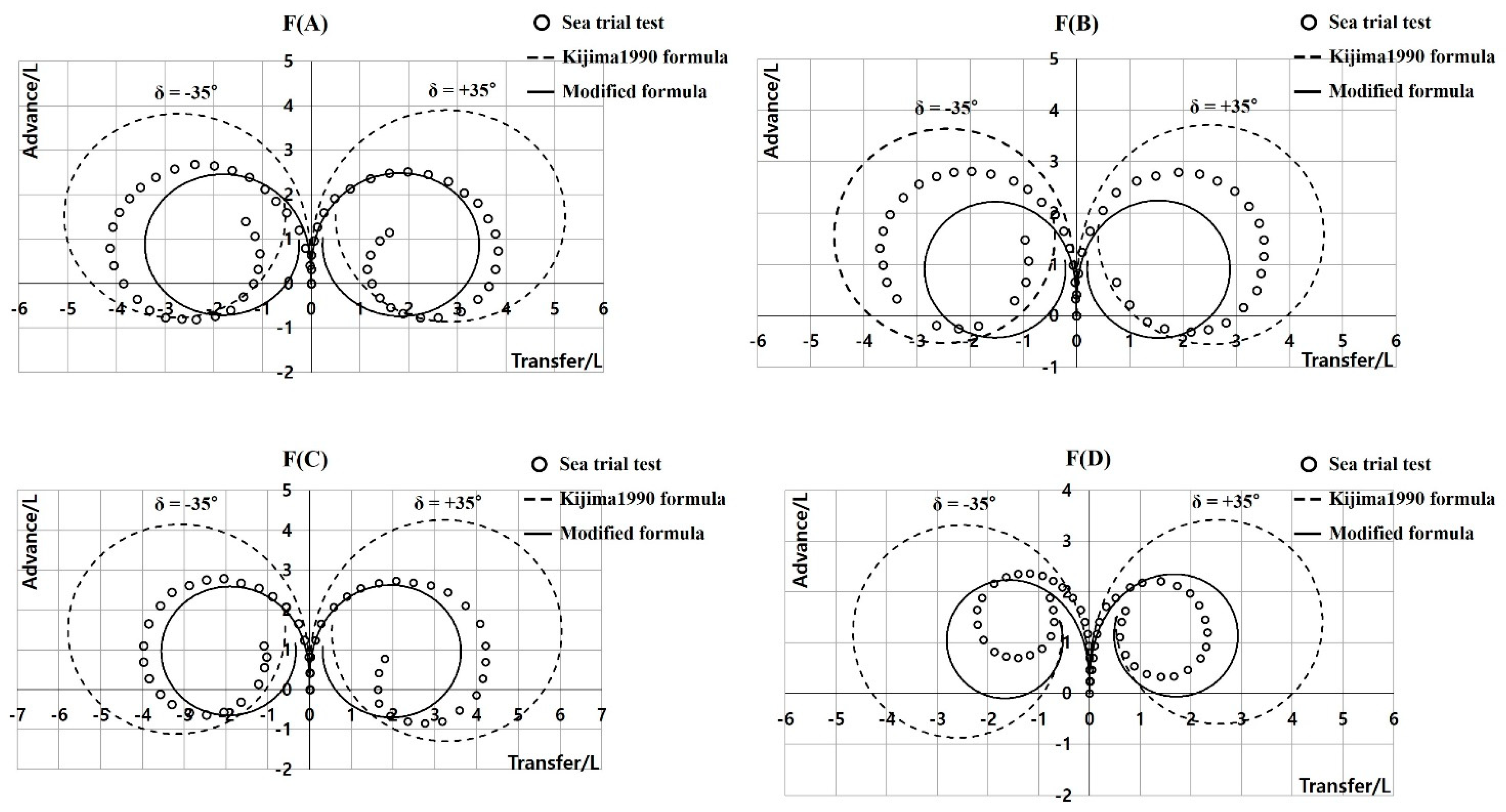
Figure 5 show the comparison results of the turning motion simulation and the sea trial test for four of the five model trawl fishing vessels used in the derivation process of the modified empirical formula, excluding vessel F(E) that was under construction at the time of testing. The numerical values listed in
Table 3 represent the average for the vessels F(A) to F(D) shown in
Figure 5 and the result of the sea trial test that was scaled to “1”.
The size of the turning trajectory derived from Kijima et al. (1990) empirical formula was larger than the results from the sea trial test with an average error of 49%. Conversely, the size of the turning trajectory derived from the modified empirical formula was smaller than the sea trial results [except for F(D)] and showed an average error of 6%. This indicates that the modified empirical formula more closely approximated the results from the sea trial test [
10].
3. Estimation of Trawl Fishing Vessel Maneuverability
The basic research discussed in
Section 2.3.4 confirmed that the modified empirical formula improves results when compared with Kijima et al. (1990) original formula in estimating the maneuverability of trawl fishing vessel hull forms.
In this chapter, the maneuvering hydrodynamic derivatives of the model trawl fishing vessel F(E) are derived, on which the validation study of the modified empirical formula was not performed due to the vessel still being under construction at the time of testing. A maneuverability simulation is performed for the tests included in the IMO maneuverability evaluation list. In addition, an in-depth verification study was conducted to determine the validity of the modified empirical formula by comparing the results with those from the sea trial test.
The basic purpose of this study is to minimize the estimation error that may occur in the design stage of fishing vessels when using the empirical formula meant for merchant ships’ hull form. In addition, it is important to check whether the accuracy of estimation can be improved by merely including the hull form parameters of fishing vessels in the empirical formula originally developed for merchant ships’ hull form [
8].
3.1. Selection of Target Fishing Vessel
The target model trawl fishing vessel is vessel F(E) in
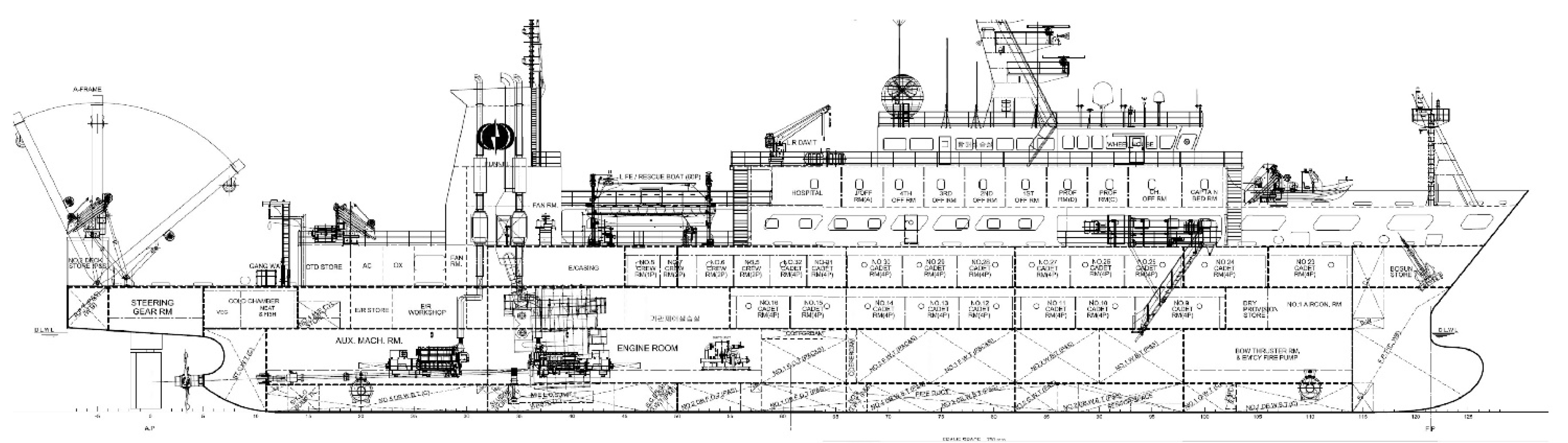
Table 2 (hereafter referred to as the target trawler). It is a training vessel that has the hull form of a trawl fishing vessel. The specifications of this vessel was included in the process for deriving the modified empirical formula, but it was excluded from the validation tests using actual ships as it was still under construction at the time. In this study, the validity of the modified empirical formula was verified by conducting in-depth validation studies (turning test, zigzag test, and time history for the target trawler). The main specifications of the target trawler are shown in
Table 4, and the body plan and general arrangement are shown in
Figure 6.
3.2. Deriving Hydrodynamic Derivatives
To perform the maneuverability simulation of the target trawler, the
hydrodynamic derivatives were derived from Kijima et al. (1990) empirical formula presented in Equation (7) and modified empirical formula presented in Equation (8). The derivatives that are derived from the two empirical formulas can be categorized into the forces and moments acting on the hull and interaction forces acting among the hull, propeller, and rudder. The right-hand sides of Equations (7) and (8) demonstrate that the
hydrodynamic derivatives obtained through the empirical formula are affected by hull form parameters. That is, since the empirical formula was developed through the process of regression analysis of the results of the model test, the relative accuracy of estimation may differ depending on the hull form of interest; an accurate estimation can be obtained for hull forms that are similar or equivalent to the ones used in the derivation of empirical formula, whereas the accuracy tends to suffer when applying the formula to a different hull form. In particular, the interaction forces are more difficult to estimate at the design stage because it represents complex hydrodynamic forces occurring among the hull, propeller, and rudder; even today, it is estimated by considering the unique characteristics of the same or a similar hull form [
16].
However, since the purpose of this study is to verify whether the estimation of the maneuverability of the hull form of fishing vessels can be improved merely by adding the hull form parameters of the fishing vessels to the empirical formula originally developed for merchant ships’ hull form, all hydrodynamic derivatives were derived through Equations (7) and (8) with no additional corrections.
Table 5 shows the hydrodynamic derivatives of the target trawler [
8].
3.3. Maneuverability Evaluation
3.3.1. Maneuverability Evaluation Conditions
To evaluate the ship’s performance, a maneuvering trial must be performed on both the port and starboard sides under the conditions specified below [
1]:
However, unlike the simulation performed using the empirical formula, it was not possible to perfectly match the above conditions during the sea trial test due to unavoidable circumstances in the field. Therefore, we approximated the test conditions to the above specifications to the best of our ability. The difference in external force conditions may affect the verification result to some extent, but because the basic purpose of this study is to verify the validity of the modified empirical formula, we have decided to set aside such a difference for the present study.
Table 6 shows the conditions for the actual test and the simulation of the target trawler.
3.3.2. Turning Motion Test
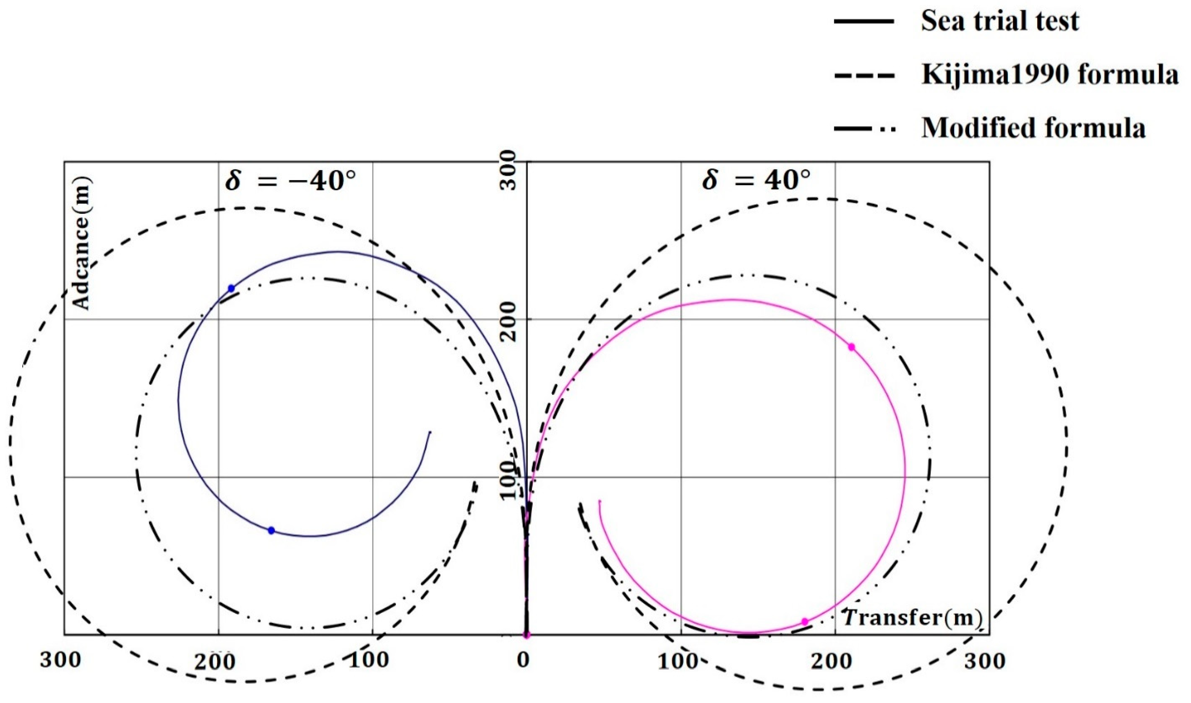
As shown in
Table 7 and
Figure 7, the simulation results from Kijima et al. (1990) empirical formula and from the modified empirical formula satisfy the IMO maneuverability criteria. Kijima et al. (1990) empirical formula generated an estimation error of 0.5L for mean advance and 1.2L for mean tactical diameter. The modified empirical formula only generated an error for mean tactical diameter of size 0.1L. In addition, as shown in
Figure 5, the absolute size of the trajectory was larger in Kijima et al. (1990) formula than in the modified formula.
As was mentioned in
Section 3.3.1, since the effect of external force was considered in the sea trial test, the shape of the turning trajectory of the port and starboard sides was slightly different than the simulation result. This can be explained by considering and analyzing the effect of wind described in
Table 6. At the time of the sea trial test, the target trawler turned when the wind was blowing from the relative bearing of 205–206° or the port side of its stern. At that moment, until the turn began, the influence of the wind blowing from the port acted to obstruct the turn. As a result, the advance tended to be slightly longer in this instance compared to turning to the starboard side. From the moment the turn began, the wind blowing from the port side of the ship’s stern assisted with the turn, which led to a faster turn compared to a turn to the starboard side (
Figure 7).
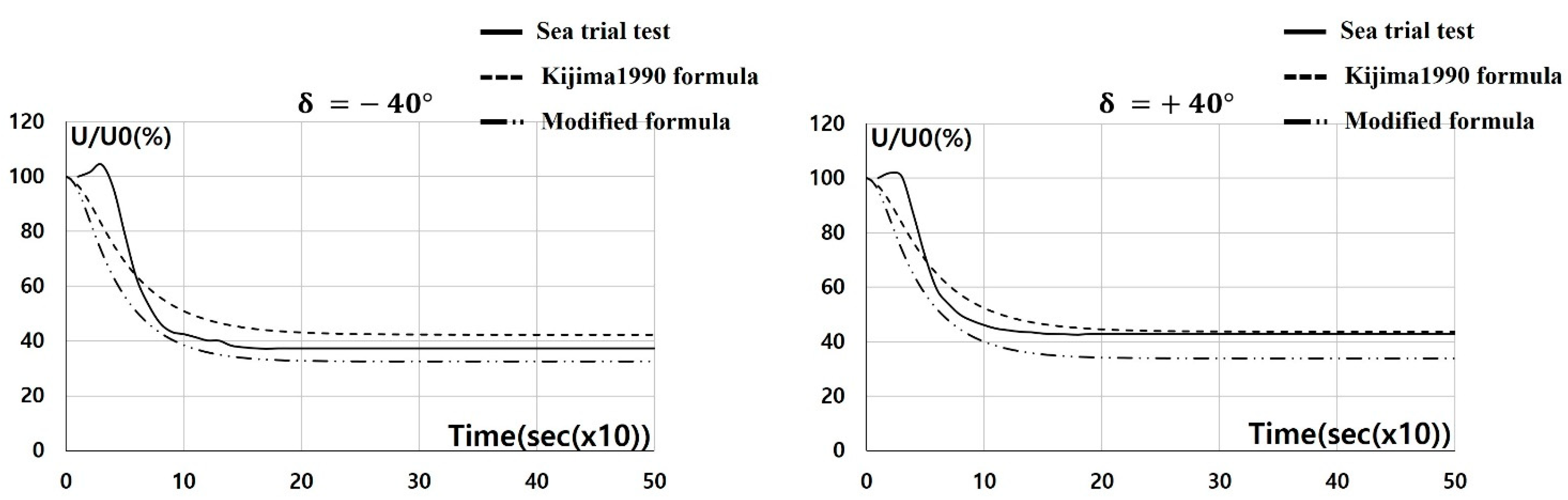
Table 8 and
Figure 8 demonstrate the change in ship speed until steady turning occurred during the turning motion of the target trawler. In all three cases, the final speed was reduced when compared with the initial speed. This is due to the drag generated from the rudder plate and the drag generated around the hull during the turning motion. It is common knowledge that such reduction in the initial speed can be ~30–40% for general ships and as much as 70–80% for VLCC [
27].
In
Table 8, the deceleration rate of the target trawler estimated by Kijima et al. (1990) empirical formula was 57.1%, and thus, was lower than the observed average of 60% from both port and starboard sides by 2.9 percentage points. The modified empirical formula resulted in an average of 66.9%, or 6.9 percentage points higher than the observed average. Quantitatively, these results indicate that the results of Kijima et al. (1990) empirical formula are closer to the actual test results. However, when evaluating the section from 0- to 100-s mark in
Figure 8, the qualitative results from the modified empirical formula demonstrate a trend that resembles the sea trial test results better. That is, the sea trial test and the modified empirical formula rapidly drop in the section from 0- to 100-s mark to reach the final speed, whereas Kijima et al. (1990) empirical formula produces a more gradual change.
The 60% deceleration rate during the sea trial test of the target trawler is far off the general merchant ships range and is close to the range associated with VLCC. We surmise that the following two forces were in action here: the drag force generated from the large rudder area ratio—one of the characteristics of the fishing vessel—and the component of drag force generated from the hull specification
—similar to the VLCC. A detailed study on this result will be performed in the future [
10].
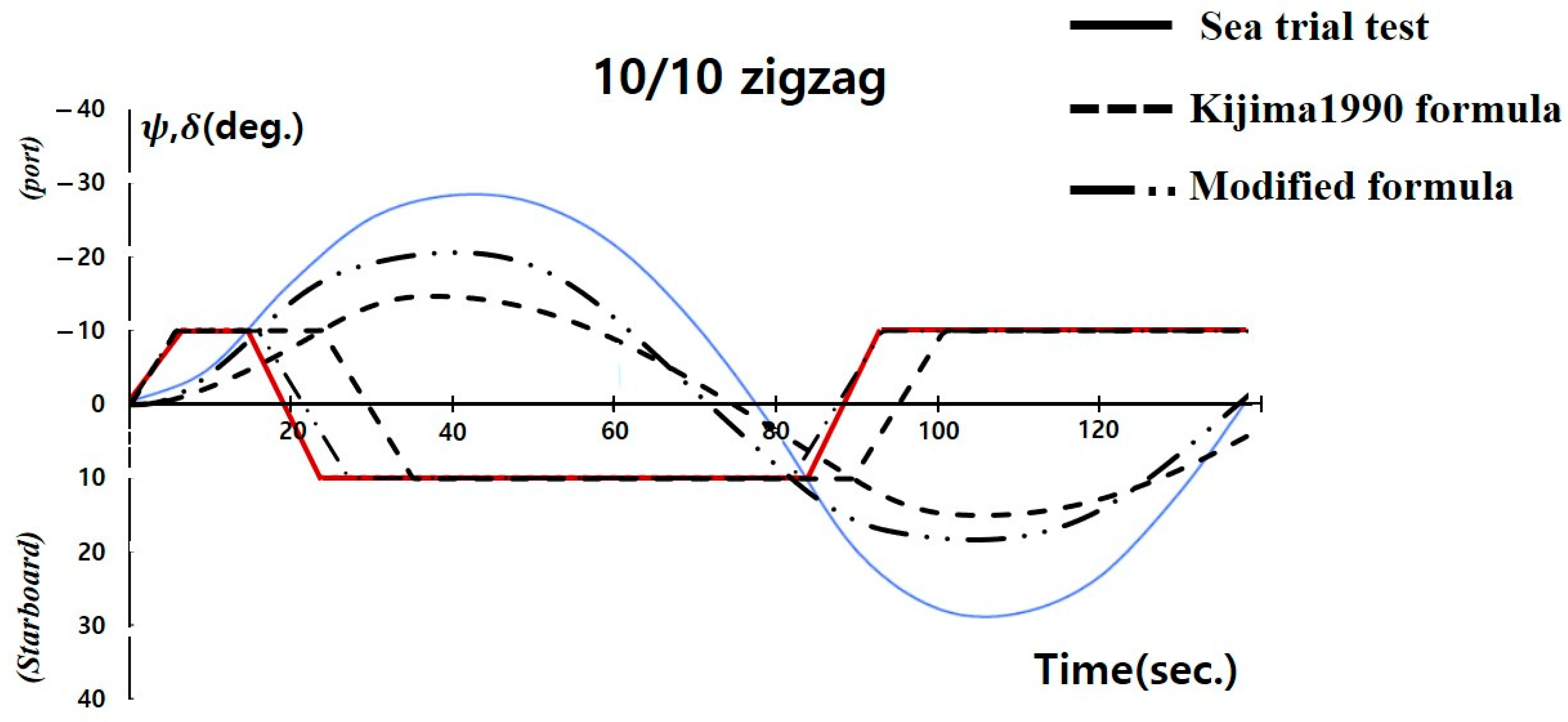
3.3.3. 10/10 Zigzag Test
The 10/10 zigzag test results of the target trawler are shown in
Table 9 and
Figure 9. Prior to the analysis, the target trawler had a length-speed ratio (L/V; LBP [m]/Speed [m/s]) of 11.1 s [
1], and the first overshoot angle exceeded the IMO Criteria 10.55° by 7.55°. However, since the target trawler is not a ship subject to the IMO standards, and the purpose of this study is to check the validity of the modified empirical formula and to improve the estimation accuracy, a study that analyzes the sea trial test results alone is excluded.
In the case of the first overshoot angle, the results from the sea trial test, modified empirical formula, and Kijima et al. (1990) empirical formula were 18.1°, 10.7°, and 4.6°, respectively. Concerning the results of the two empirical formulas, the modified empirical formula was able to approximate the sea trial test result better. For the second overshoot angle, the corresponding results from the sea trial test, modified empirical formula, and Kijima et al. (1990) empirical formula were 18.4°, 8.4°, and 5.0°, respectively. The results of the modified empirical formula were slightly closer to the experimental test results than those of Kijima et al. (1990) empirical formula.
The absolute value of the overshoot angle was slightly different between the sea trial test and the two empirical formulas. This reflects the unique hull form characteristics of the target trawler. Various factors contribute to the maintenance of a vessel’s course-keeping qualities, and the rudder area ratio plays an important part. The larger the rudder, the better the rudder effect. However, a larger rudder has the disadvantage in terms of decreased speed due to resistance. In the case of a fishing vessel’s, the rudder area ratio is generally larger than that of merchant ships’ because it requires quick maneuverability to track fish. The rudder area ratio is expressed as the ratio of the rudder area to the longitudinal cross-sectional area of the hull below the water line. In the maximum level of draft, the ratio is typically 1/60 to 1/70 for general merchant ships, 1/35 to 1/40 for fishing vessels, and 1/30 to 1/50 for military vessels [
27].
4. Conclusions
Due to the lack of research on estimating the maneuverability for the hull forms of fishing vessels, the empirical formula originally developed for merchant ships’ hull form is being used even for fishing vessels. Since the empirical formula was derived by regression analysis of the model test results of merchant ships’ hull form, the process led to estimation errors when applied to the hull form of fishing vessels with different hull form characteristics.
With these in mind, we derived a modified empirical formula by adding the hull form parameters of fishing vessels’ using Kijima et al. (1990) empirical formula, which had originally been developed for merchant ships’ hull form. Using the modified empirical formula, this study estimated the maneuverability of the trawl fishing vessel hull form and compared the result with that from the sea trial test.
The turning motion test revealed that the estimation errors of Kijima et al. (1990) empirical formula were 0.5L for mean advance and 1.2L for mean tactical diameter when compared to the results from the sea trial test, whereas the modified empirical formula only generated an error of 0.1L in mean tactical diameter. This finding suggests that the latter quantitatively and qualitatively produces better approximation.
From the 10/10 zigzag test, we also observed that Kijima et al. (1990) and modified empirical formulas generated estimation errors of 13.5° and 7.4° for the first overshoot angle, respectively; the corresponding values for the second overshoot angle were 13.4° and 10.0°, respectively. These results also confirmed that the modified empirical formula offered better approximation to the results from the sea trial test both quantitatively and qualitatively.
The present study also aided in understanding how much the unique characteristics of hull form parameters associated with each vessel could impact the derivation process for empirical formulas. Moreover, it could also be seen that the characteristics of rudders, propellers, and other auxiliary components may engender varying motion characteristics of ships even when they are of the same type and have similar hull forms to one another.
We verified that modifying existing empirical formulas originally developed for hull forms of merchant ships by simply adding the hull form parameters of fishing vessels can improve their estimation results. It was also confirmed that even a slight difference in the characteristics of hulls, propellers, or rudders can introduce differing motion characteristics, thus leading to estimation errors—even when the ships of interest are of the same type. These results reaffirm the need for an empirical formula tailored to the hull forms of fishing vessels, as well as the need for a process for systematically updating previously developed empirical formulas with additional modifications.
As the present study focused on validating the performance of the modified empirical formula, we intend to build upon the results obtained here to conduct more detailed studies on the bank effect and ship-to-ship [
28,
29] comparisons of fishing vessels’ hull forms in the future. Such a study would serve as a good indicator for those who operate fishing vessels and play an important role in analyzing maritime accidents should they occur.
Author Contributions
Conceptualization, S.-H.K.; methodology, S.-H.K.; software, C.-K.L.; analysis, S.-H.K.; writing—original draft preparation, S.-H.K.; writing—reviewing and editing, C.-K.L.; supervision, S.-H.K. All authors have read and agreed to the published version of the manuscript.
Funding
This research received no external funding.
Institutional Review Board Statement
Not applicable.
Informed Consent Statement
Not applicable.
Data Availability Statement
The data used to support the findings of this study are available from the corresponding author upon request.
Acknowledgments
This research was supported by the ‘Development of Autonomous Ship Technology (20200615) ‘funded by the Ministry of Oceans and Fisheries (MOF, Korea).
Conflicts of Interest
The authors declare no conflict of interest.
Nomenclature
| rudder area |
| rudder force increase factor |
| coefficient for starboard and port rudder |
| rudder normal force gradient coefficient |
| constants |
| constants |
| propeller diameter |
| normal force acting on the rudder/non-dimensionalized |
| rudder height |
| inertia moment of axis direction, added inertia moment/non-dimensionalized |
| advance coefficient |
| aspect ratio of the rudder |
| thrust coefficient |
| mass of ship, added mass of x axis direction, added mass of y axis direction/non-dimensionalized |
| propeller revolution |
| propeller revolution |
| slip ratio |
| thrust deduction coefficient in straight forward moving direction |
| steering deduction factor |
| resultant velocity, drift angle, rudder angle |
| effective rudder inflow speed |
| velocity components at the center of gravity of ship and yaw rate about z axis |
| effective wake coefficient at the position of the propeller |
| effective wake coefficient at the position of the rudder |
| effective wake coefficient at the position of the propeller in straight forward moving direction |
| effective wake coefficient at the position of the rudder in straight forward moving direction |
| distance between C.G and the center of additional lateral force/non-dimensionalized |
| longitudinal coordinate of the position of the rudder/non-dimensionalized |
| effective rudder inflow angle |
| effective inflow angle to the rudder in maneuvering motion/non-dimensionalized |
| rudder angle |
| |
| flow straightening coefficient |
| effective wake fraction at the position of the propeller |
| · (dot) | derivative with respect to time |
| ′ (prime) | non-dimensionalized quantity |
References
- IMO MSC 76/23. “Standards for Ship Manoeuvrability” Report of the Maritime Safety Committee on Its 76th Session-Annex 6; Resolution MSC 137(76); IMO: London, UK, 2002; pp. 1–6. [Google Scholar]
- Yoshimura, Y.; Ma, N.; Suzuki, S.; Kajiwara, Y. Manoeuvring Performance of the Fishing vessel Modified by a Bulge. J. Soc. Nav. Archit. Jpn. 2002, 192, 37–46. [Google Scholar] [CrossRef]
- Yoshimura, Y.; Ma, N. Manoeuvring Prediction of Fishing vessel. In MARSIM 03′Conference Proceedings; The Society of Naval Architects of Japan, Japan Institute of Navigation and International Marine Simulator Forum: Kanazawa, Japan, 2003; RC-29-1-10. [Google Scholar]
- Obreja, D.; Nabergoj, R.; Crudu, L.; Păcuraru-Popoiu, S. Identification of hydrodynamic coefficients for manoeuvring simulation model of a fishing vessel. Ocean Eng. 2010, 37, 678–687. [Google Scholar] [CrossRef]
- Lee, C.K.; Kim, S.H.; Lee, J.G.; Lee, S.M.; Kim, M.S. A Study on the Characteristics of Manoeuvrability of Fishing Vessel. J. Korean Soc. Fish. Ocean Technol. 2018, 54, 239–245. [Google Scholar] [CrossRef]
- Lee, C.K.; Kim, S.H.; Yim, J.B.; Lee, S.M. Study on the Maneuvering Characteristics of a Fishing Vessel in Shallow Water. Nav. Eng. J. 2019, 131–132, 95–104. [Google Scholar]
- Lee, C.K.; Kim, S.H.; Lee, S.M.; Yim, J.B. Study on the Manoeuvring prediction of a fishing vessel. Nav. Eng. J. 2019, 131–134, 101–109. [Google Scholar]
- Kim, S.H.; Lee, C.K.; Lee, S.M. Estimation of Maneuverability of Fishing Vessel Considering Hull-Form Characteristics. J. Mar. Sci. Eng. 2021, 9, 569. [Google Scholar] [CrossRef]
- Yoshimura, Y.; Yasukawa, H. Introduction of MMG Standard Method for Ship Maneuvering Predictions. J. Mar. Sci. Technol. 2015, 20, 37–52. [Google Scholar] [CrossRef]
- Kim, S.H. A Study on the Improvement of the Accuracy of Fishing Vessels Manoeuvrability Prediction. Ph.D. Thesis, Korea Maritime and Ocean University, Busan, Korea, 2020. [Google Scholar]
- Yoshimura, Y.; Masumoto, Y. Hydrodynamic Force with Medium High Speed Merchant Ships Including Fishing Vessels and Investigation into a Manoeuvring Prediction Method. J. Jpn. Soc. Nav. Archit. Ocean Eng. 2011, 14, 63–73. [Google Scholar] [CrossRef][Green Version]
- Lee, M.K.; Park, Y.S. Collision Prevention Algorithm for Fishing Vessels Using WAVE Communication. J. Mar. Sci. Eng. 2020, 8, 115. [Google Scholar] [CrossRef]
- Jung, C.H. A Study on the Improvement of Safety by Accidents Analysis of Fishing Vessels. J. Fish. Mar. Sci. Educ. 2018, 30, 179–186. [Google Scholar]
- Kim, S.H.; Kim, H.S.; Lee, Y.W. The Causes and Counterplan for Marine Casualties of Fishing Vessels According to the Fishing Types. J. Korean Soc. Fish. Ocean Technol. 2020, 56, 246–257. [Google Scholar] [CrossRef]
- Lee, M.K.; Park, Y.S.; Park, S.W.; Lee, E.K.; Park, M.J.; Kim, N.E. Application of Collision Warning Algorithm Alarm in Fishing Vessel’s Waterway. Appl. Sci. 2021, 11, 4479. [Google Scholar] [CrossRef]
- Kijima, K.; Katsuno, T.; Nakiri, Y.; Furukawa, Y. On the Manoeuvring Performance of a Ship with the Parameter of Loading Condition. J. Soc. Nav. Archit. Jpn. 1990, 168, 141–148. [Google Scholar] [CrossRef]
- Result of Sea Trial Test; Dae Sun Shipbuilding & Engineering Co., Ltd.: Busan, Korea, 2020.
- Ogawa, A.; Koyama, T.; Kijima, K. MMG report-I, on the Mathematical Model of Ship Manoeuvring. Bull. Soc. Nav. Archit. Jpn. 1977, 575, 22–28. [Google Scholar]
- Kobayashi, E.; Kagemoto, H.; Furukawa, Y. Mathematical Models of Ship Manoeuvring Motion; 2nd symposium. J. Soc. Nav. Arch. 1995, 1995, 23–84. [Google Scholar]
- Kijima, K.; Nakiri, Y. Approximate Expression for Hydrodynamic Derivatives of Ship Manoeuvring Motion Taking into Account of the Effect of Stern Shape. Trans. West Jpn. Soc. Nav. Arch. 1999, 98, 67–77. [Google Scholar]
- Kijima, K.; Nakiri, Y. On the Practical Prediction Method for Ship Manoeuvring Characteristics. Trans. West Jpn. Soc. Nav. Arch. 2003, 105, 21–31. [Google Scholar]
- Kim, K.Y. Manoeuverabilities of the M.S “SAEBADA”. J. Korean Soc. Fish. Ocean Technol. 1979, 12, 209–215. [Google Scholar]
- Kim, M.S.; Shin, H.O.; Kang, K.M.; Kim, M.S. Variation of Turning Circle by the Rudder Angle and the Ship’s Speed. J. Korean Soc. Fish. Ocean Technol. 2005, 41, 156–164. [Google Scholar] [CrossRef]
- Ahn, Y.H.; Park, M.H.; Choi, C.M.; Chung, Y.J. A Study on the Maneuverabilities of the Training ship M.S. A-RA. J. Korean Soc. Fish. Ocean Technol. 2001, 37, 275–284. [Google Scholar]
- An, Y.S.; Kang, I.K.; Kim, H.S.; Kim, J.C.; Kim, M.S.; Jo, H.J.; Lee, C.K. A Study on the Manoeuvrability of T/S SAEBADA by Real sea trials. J. Korean Soc. Fish. Ocean Technol. 2005, 41, 289–295. [Google Scholar] [CrossRef][Green Version]
- Kim, M.S.; Shin, H.I.; Kim, J.H.; Kang, I.K. A Study on the Maneuverabilities of the T.S KAYA. J. Fish. Mar. Sci. Educ. 2009, 21, 59–67. [Google Scholar]
- Yoon, J.D. Theory and Practice of Ship Manoeuvring; Sejong Publishing Co.: Busan, Korea, 2019. [Google Scholar]
- Huang, J.; Xu, C.; Xin, P.; Zhou, X.; Sutulo, S.; Soares, C.G. A Fast Algorithm for the Prediction of Ship-Bank Interaction in Shallow Water. J. Mar. Sci. Eng. 2020, 8, 927. [Google Scholar] [CrossRef]
- Hong, C.B.; Lee, S.M. A Study on Barge-Bank Interaction Forces Considering the Reflected Waves. J. Mar. Sci. Eng. 2020, 8, 451. [Google Scholar] [CrossRef]
Figure 1.
Coordinate system.
Figure 1.
Coordinate system.
Figure 2.
Relationship between and of the model ships.
Figure 2.
Relationship between and of the model ships.
Figure 3.
Comparison of the hull form parameters of the model ships.
Figure 3.
Comparison of the hull form parameters of the model ships.
Figure 4.
Correlations between linear derivatives and hull form parameters of the model ships.
Figure 4.
Correlations between linear derivatives and hull form parameters of the model ships.
Figure 5.
Comparison of the turning motion test results of the model trawl fishing vessels.
Figure 5.
Comparison of the turning motion test results of the model trawl fishing vessels.
Figure 6.
Body plan and general arrangement of the target trawler.
Figure 6.
Body plan and general arrangement of the target trawler.
Figure 7.
Comparison of the turning motion test results of the target trawler.
Figure 7.
Comparison of the turning motion test results of the target trawler.
Figure 8.
Comparison of the speed deceleration rate during the turning motion of the target trawler (where U is the speed for each section and U0 is the initial speed).
Figure 8.
Comparison of the speed deceleration rate during the turning motion of the target trawler (where U is the speed for each section and U0 is the initial speed).
Figure 9.
Comparison of the 10/10 zigzag test results for the target trawler.
Figure 9.
Comparison of the 10/10 zigzag test results for the target trawler.
Table 1.
Main specifications of model merchant ships (Kijima et al., 1990).
Table 1.
Main specifications of model merchant ships (Kijima et al., 1990).
| | | | | | |
|---|
| A (VLCC) | 2.5 | 0.436 | 0.157 | 0.802 | 5.734 |
| B (VLCC) | 2.5 | 0.408 | 0.170 | 0.831 | 6.127 |
| C (ULCC) | 2.5 | 0.466 | 0.156 | 0.835 | 5.365 |
| D (ULCC) | 2.5 | 0.555 | 0.183 | 0.821 | 4.505 |
| E (ULCC) | 2.5 | 0.500 | 0.183 | 0.820 | 5.000 |
| F (Cargo) | 2.5 | 0.408 | 0.171 | 0.773 | 6.127 |
| G (Cargo) | 2.5 | 0.419 | 0.140 | 0.698 | 5.967 |
| H (Cargo) | 2.5 | 0.376 | 0.158 | 0.651 | 6.649 |
| I (Container) | 3.0 | 0.435 | 0.163 | 0.572 | 6.897 |
| J (Container) | 2.5 | 0.386 | 0.130 | 0.566 | 6.477 |
| K (RO/RO) | 2.5 | 0.367 | 0.102 | 0.557 | 6.812 |
| L (Car carrier) | 2.5 | 0.482 | 0.134 | 0.522 | 5.187 |
| M (LNG) | 2.5 | 0.409 | 0.100 | 0.714 | 6.112 |
Table 2.
Main specifications of the five model trawl fishing vessels.
Table 2.
Main specifications of the five model trawl fishing vessels.
| | | | | | |
|---|
| F(A) | 3.0 | 0.576 | 0.211 | 0.607 | 5.208 |
| F(B) | 3.0 | 0.609 | 0.223 | 0.610 | 4.927 |
| F(C) | 3.0 | 0.546 | 0.207 | 0.574 | 5.492 |
| F(D) | 3.0 | 0.529 | 0.184 | 0.587 | 5.667 |
| F(E) | 3.0 | 0.544 | 0.187 | 0.592 | 5.520 |
Table 3.
Quantitative comparison of the turning motion test results of the model trawl fishing vessels.
Table 3.
Quantitative comparison of the turning motion test results of the model trawl fishing vessels.
| | Sea Trial Test | Kijima et al. (1990) | Modified Formula |
|---|
| Advance | 1 | 1.43 (43%↑) | 0.93 (7%↓) |
| Transfer | 1 | 1.55 (55%↑) | 0.96 (4%↓) |
| Tactical Dia. | 1 | 1.50 (50%↑) | 0.95 (5%↓) |
| Average | 1 | 1.49 (49%↑) | 0.94 (6%↓) |
Table 4.
The main specifications of the target trawler.
Table 4.
The main specifications of the target trawler.
| | Target Trawler |
|---|
| Hull | | 85.0 |
| 15.4 |
| 5.3 |
| 0.592 |
| Rudder | | 7.631 |
| Max. (deg.) | 45.0 |
| Propeller | Rotation | Right |
| No. of blades | 4 |
| 3.8 |
Table 5.
The hydrodynamic derivatives of the target trawler.
Table 5.
The hydrodynamic derivatives of the target trawler.
| | Hydrodynamic Derivatives | Kijima et al.(1990) Formula | Modified Formula |
|---|
| Hull | | 0.3461 | 0.3325 |
| 0.8509 | 0.7712 |
| −0.1610 | −0.1891 |
| −0.0001 | −0.0024 |
| 0.8351 | 0.6456 |
| −0.3442 | −0.2890 |
| 0.1247 | 0.1148 |
| −0.0687 | −0.0380 |
| −0.0518 | −0.0499 |
| −0.0363 | −0.0270 |
| −0.0520 | −0.0703 |
| −0.2877 | −0.3248 |
| Interaction | | 0.7158 | 0.7421 |
| 0.3077 | 0.5311 |
| −1.4767 | −0.9638 |
| 0.2462 | 0.2929 |
| 0.3175 | 0.4063 |
| 0.9053 | 0.8396 |
| 0.4265 | 0.3112 |
Table 6.
Maneuverability evaluation conditions.
Table 6.
Maneuverability evaluation conditions.
| | Turning Motion | 10/10 Zigzag Test |
|---|
| | Sea Trial Test | Simulations | Sea Trial Test | Simulations |
|---|
| Wind direction (Relative) and Speed | PORT: 205°, 3.8 m/s
STBD: 206°, 4.1 m/s | calm | 341°, 7.0 m/s | calm |
| Water depth | ~130 m | | ~130 m | |
| Ship draft (m) | FWD: 5.18
AFT: 5.28 | FWD: 5.3
AFT: 5.3 | FWD: 5.18
AFT: 5.28 | FWD: 5.3
AFT: 5.3 |
| Test speed (kts) | PORT: 14.2
STBD: 14.52 | PORT: 14.04
STBD: 14.04 | 14.81 | 14.04 |
Table 7.
Quantitative comparison of the turning motion test results of the target trawler.
Table 7.
Quantitative comparison of the turning motion test results of the target trawler.
| | | Sea Trial Test | Kijima et al.
(1990) Formula | Modified Formula | IMO Criteria |
|---|
| Advance (m) | PORT | 241 (2.8L) | 272 (3.2L) | 224 (2.6L) | (4.5L) |
| STBD | 212 (2.5L) | 277 (3.3L) | 229 (2.7L) |
| Mean | 227 (2.7L) | 275 (3.2L) | 227 (2.7L) |
| Tac. Dia. (m) | PORT | 225 (2.6L) | 330 (3.9L) | 250 (2.9L) | (5.0L) |
| STBD | 245 (2.9L) | 343 (4.0L) | 260 (3.0L) |
| Mean | 235 (2.8L) | 337 (4.0L) | 255 (3.0L) |
Table 8.
Comparison of the speed deceleration rate during the turning motion for the target trawler.
Table 8.
Comparison of the speed deceleration rate during the turning motion for the target trawler.
| | Turning Motion |
|---|
| | Sea Trial Test | Kijima et al.
(1990) Formula | Modified Formula |
|---|
| Rudder angle () | −40 | +40 | −40 | +40 | −40 | +40 |
| Initial speed (kts) | 14.2 | 14.52 | 14.04 | 14.04 | 14.04 | 14.04 |
| Final speed (kts) | 5.29 | 6.22 | 5.93 | 6.12 | 4.56 | 4.73 |
| Speed reduction rate (%) | 62.7 | 57.2 | 57.8 | 56.4 | 67.5 | 66.2 |
Table 9.
Comparison of the 10/10 zigzag test results for the target trawler.
Table 9.
Comparison of the 10/10 zigzag test results for the target trawler.
| | Sea Trial Test | Kijima et al.
(1990) Formula | Modified Formula | IMO Criteria |
|---|
| Initial course (°) | 60 | 60 | 60 | |
| Initial speed (kts [m/s]) | 14.81 [7.65] | 14.04 [7.22] | 14.04 [7.22] | |
| L/V (s) | 11.1 | 11.8 | 11.8 | |
| 1st over shoot angle (°) | 18.1 | 4.6 | 10.7 | (5 + 1/2 (L/V)) |
| 2nd over shoot angle (°) | 18.4 | 5.0 | 8.4 | (17.5 + 0.75 (L/V)) |
| Publisher’s Note: MDPI stays neutral with regard to jurisdictional claims in published maps and institutional affiliations. |
© 2021 by the authors. Licensee MDPI, Basel, Switzerland. This article is an open access article distributed under the terms and conditions of the Creative Commons Attribution (CC BY) license (https://creativecommons.org/licenses/by/4.0/).


