Article

Vertical Profile Diving and Floating Motion Control of the Underwater Glider Based on Fuzzy Adaptive LADRC Algorithm

1
State Key Laboratory of Ocean Engineering, Shanghai Jiao Tong University, Shanghai 200240, China
2
School of Naval Architecture Ocean & Civil Engineering, Shanghai Jiao Tong University, Shanghai 200240, China
3
School of Oceanography, Shanghai Jiao Tong University, Shanghai 200240, China
*
Author to whom correspondence should be addressed.
J. Mar. Sci. Eng. 2021, 9(7), 698; https://doi.org/10.3390/jmse9070698
Submission received: 31 May 2021 / Revised: 21 June 2021 / Accepted: 21 June 2021 / Published: 25 June 2021
(This article belongs to the Special Issue Maritime Autonomous Vessels)

Abstract

:
The underwater glider is a kind of novel invention that has been proven to be perfect for long-duration, wide-range marine environmental monitoring tasks. It is controlled by changing the buoyancy and adjusting the posture. For precise control of the underwater glider’s trajectory, a fuzzy adaptive linear active disturbance rejection control (LADRC) is designed in this paper. This controller allows the glider to dive to a predetermined depth precisely and float at a specific depth. In addition, the controller takes some important factors into account, such as model uncertainty, environmental disturbances, and the limited dynamic output of the actual mechanical actuator. Finally, simulation results show the superiority of this fuzzy adaptive LADRC control method. Particularly, when the underwater glider was controlled to dive 100 m at a predetermined attitude angle θ = −1 rad, the maximum overshoot of FLADRC is reduced by 75.1%, 56.6% relative to PID, LADRC, respectively.

1. Introduction

The oceans are vast and huge, as they comprise 71% of the Earth’s surface. There are numerous economic and military activities shifting to the oceans, and we need to understand the oceans more comprehensively. In recent years, more and more unmanned vehicles have been used in ocean exploration and development, including unmanned surface vessels [1], autonomous underwater vehicles (AUVs) [2], remotely operated vehicles, autonomous underwater gliders, integrated unmanned surface vehicle and underwater vehicle platforms [3], etc. The underwater glider is a new type of underwater vehicle that is rapidly developing and can be applied to a long time and wide range of marine environmental monitoring. It is driven by the buoyancy system to adjust the net buoyancy and the attitude system to adjust its attitude angle so as to obtain the forward propulsion by means of the wings. It is capable of sawtooth motion in the vertical profile underwater, and can also realize the three-dimensional spiral motion in underwater space [4]. Underwater gliders have the advantages of low energy consumption, low noise, and low cost, so they have ideal application prospects in the fields of marine resource exploration, marine stereo monitoring, and military exploration [5,6,7,8,9].
Research institutions in the United States, Japan, China, etc., have conducted research on underwater gliders and have developed more mature underwater gliders such as Slocum [10], Spray [11], Tsukuyomi [12], Sea-Wing [13], and Petrel [14]. The dynamic system of the underwater glider is a complex nonlinear system, which has model uncertainty in the actual physical system. Facing the changes in temperature, salinity, pressure, and currents in different seas and water depths, the underwater glider is very vulnerable to environmental disturbances due to its low speed. The actual mechanical actuator of the underwater glider has a limited dynamic output range, thus making the control input subject to saturation constraints. Considering the challenges of underwater glider control, it is important for the research and development of underwater gliders to study the control method of underwater glider vertical profile diving and floating motion so that the underwater glider can successfully perform the tasks such as floating at a specific depth and precisely reaching the predetermined depth. In recent years, as countries pay more attention to underwater gliders, research on their dynamics modeling and control analysis has been intensified. Leonard et al. [15] developed a generalized nonlinear dynamics model for underwater gliders considering the hydrodynamics of the glider and the coupling between the glider and its internal moving mass block. A control method for the pitch angle of the underwater glider was designed based on the linear quadratic regulator (LQR) control method in the vertical profile. Fan [16] designed a feedforward and feedback-based motion controller and studied the sawtooth motion and turning motion of the underwater glider under steady-state conditions in the vertical profile through simulation. Huang et al. [17] proposed a self-seeking ADRC (active disturbance rejection control) method based on the tracking differentiator and active disturbance rejection control theory. They also applied the method to pitch-hold control during descent and ascent in the vertical profile of an underwater glider and attitude transition control during the dive-float transition. Zhou et al. [18] proposed an adaptive robust sliding mode control for the virtual mooring problem of underwater gliders. The method takes into account the input constraints of the underwater glider and demonstrates the superiority of the proposed control method by simulation. Vu et al.’s study [19] is based on the dynamic sliding mode control (DSMC) theory to control the motion of the over-actuated AUV under the effects of the ocean current and model uncertainties. Xiang et al. [20] introduced three major classes of fuzzy control, including conventional fuzzy control, adaptive fuzzy control, and Hybrid Fuzzy Control in the marine robotic field. Cao et al. [21] proposed a nonlinear MIMO adaptive backstepping control to control an underwater glider in sawtooth motion, spiral motion, and multimode motion. Xu et al. [22] proposed an L1 adaptive backstepping controller for path-following control of an underactuated surface vessel based on a nonlinear steering model. Isa et al. [23] designed the neural network controller of model predictive control to predict and control the underwater glider motion. Sands [24] proposed an approach of deterministic artificial intelligence to control the motion of unmanned underwater vehicles.
Although various underwater glider motion control methods have been proposed, there are still many problems to be solved to improve the control accuracy, energy utilization and the practical availability. For example, the chattering phenomenon of the sliding mode control will increase the difficulty in engineering practice. In addition, a precise mathematical model of the control object is needed for the sliding mode control. The computational cost of neural network algorithms is also very high. In practice, underwater gliders often use PID control to adjust the attitude during descent and ascent movements in the vertical profile. In the process of diving, the underwater glider is first adjusted to the pitch angle when gliding downward, then a reasonable net buoyancy is preset according to the depth to be dived (obtained from sea trial or theoretical calculation), and finally, the glider enters the steady-state gliding stage. When the underwater glider reaches a predetermined depth, it begins the conversion process. First, the net buoyancy of the underwater glider decreases so that its speed is slowly reduced to zero. Second, the underwater glider’s pitch angle is changed from downward glide to upward glide. Finally, the net buoyancy of the underwater glider is increased to make it glide at a specific speed, thus completing the conversion control of the underwater glider and entering the upward gliding phase of the underwater glider [25]. The control method of presetting the net buoyancy of the underwater glider makes it easy to make the underwater glider fail to reach the predetermined depth or produce depth overshoot, which has relatively little effect on the underwater glider with large dive depth. However, it has a greater impact on the underwater glider with small dive depth, which will significantly affect its design performance and even threaten its own safety. It is important to optimize the control method of the underwater glider in vertical profile, so that the underwater glider can perform the tasks such as precisely reaching the predetermined depth or floating at a specific depth. This paper considers the important factors such as underwater glider model uncertainty, environmental interference, and input constraints, and designs a fuzzy adaptive LADRC control scheme acceptable to the actual mechanical system of the underwater glider.
The rest of the paper is organized as follows. Section 2 presents the modeling of the underwater glider and the formulation of the control objective. The fuzzy adaptive LADRC controller is described in Section 3, explaining how to make the glider dive to a certain depth and floating at a specific depth with environmental disturbances and input constraints. Then, to demonstrate the effectiveness of the proposed controller, simulation results compared with conventional PID and LADRC are shown in Section 4. Finally, Section 5 is the conclusion.

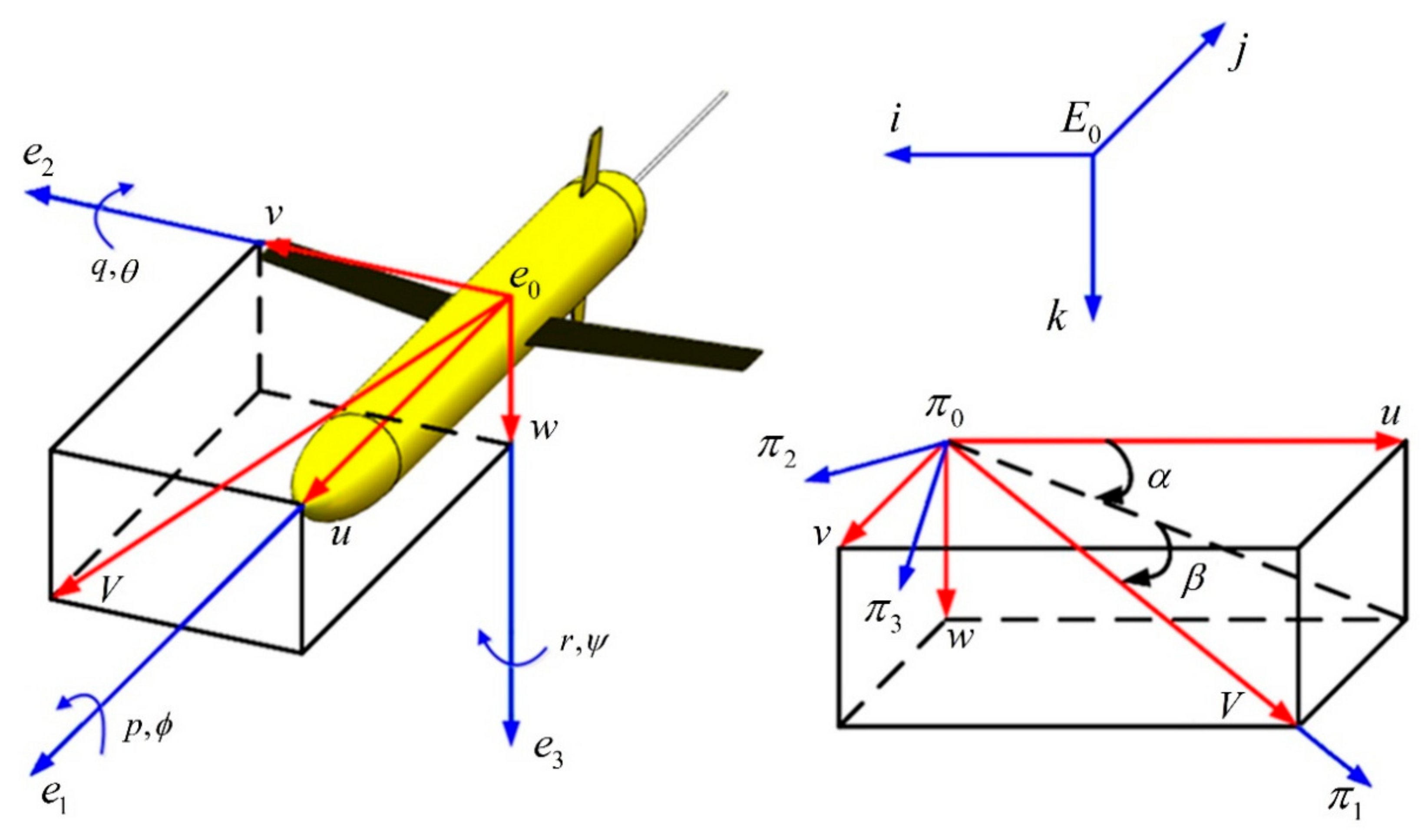
2. Dynamic Model of the Underwater Glider

The underwater glider usually works in seawater, which will involve the action of hydrodynamic forces on it, and it is a complex multi-body dynamics system. In this paper, we refer to the literature [21,25] to establish the kinematic model of the underwater glider and define the inertial coordinate system, the body coordinate system, and the fluid coordinate system of the underwater glider, which are all right-handed coordinate systems, respectively. The coordinate system of the underwater glider is shown in Figure 1.
The inertial coordinate system is used to describe the position of the underwater glider, where the k-axis is oriented in the same direction as gravity. b = [ x , y , z ] T is used to describe the position of the origin of the coordinate system of the underwater glider body, and then the dive depth of the underwater glider is denoted by z . We define the glider’s cross-roll angle as ϕ , pitch angle as θ , and yaw angle as ψ , respectively; thus, b θ = [ ϕ , θ , ψ ] T can be used to represent the attitude of the underwater glider. The body coordinate system is used to describe the state of motion of the underwater glider, where the e 1 -axis coincides with the longitudinal axis of the underwater glider and points to the bow, the e 2 -axis coincides with the wing plane of the underwater glider and points to the right, and the e 3 -axis points to the bottom of the glider. The fluid coordinate system is defined to describe the lift and drag force of the glider, where the π 1 -axis points to the velocity direction of the glider. The velocity of the underwater glider with respect to the current is assumed to be zero. Thus, the velocity of the underwater glider with respect to the current is equal to the velocity of the underwater glider V = [ u , v , w ] T , and α = arctan ( w / u ) , β = arcsin ( v / V ) .
The kinematic equations aim to establish the connection between the state quantities of motion of the underwater glider in the body coordinate system and the state quantities of position in the inertial coordinate system. The kinematic equations of the glider expressed in terms of Euler angles can map the vectors in the body coordinate system to the inertial coordinate system by rotating the coordinate matrix.
b ˙ b ˙ θ = R E B V R E Ω Ω
where R E B is the coordinate/velocity mapping matrix from the body coordinate system to the inertial coordinate system. R E Ω is the angle/angular velocity mapping matrix from the body coordinate system to the inertial coordinate system.
R E B = cos θ cos ψ sin ϕ sin θ cos ψ cos ϕ sin ψ cos ϕ sin θ cos ψ + sin ϕ sin ψ cos θ sin ψ cos ϕ cos ψ + sin ϕ sin θ sin ψ sin ϕ cos ψ + cos ϕ sin θ sin ψ sin θ sin ϕ cos θ cos ϕ cos θ
R E Ω = 1 sin ϕ tan θ cos ϕ tan θ 0 cos ϕ sin ϕ 0 sin ϕ sec θ cos ϕ sec θ
References [15,18,26] assumes that the motion of the underwater glider in roll, yaw was neglected; the coupling terms for smaller values of v , w , p , q , and r are neglected in equilibrium; and the values of α and β are small. Then, the simplified equations of motion of the underwater glider neglecting the nonlinear coupling terms between different planes can be described as (4).
ϕ ˙ = p + q sin ϕ tan θ + r cos ϕ tan θ θ ˙ = q cos ϕ r sin ϕ ψ ˙ = q sin ϕ sec θ + r cos ϕ sec θ p ˙ = 1 I f 1 K M R K M 0 u w + K p p u 2 m p R p g cos θ cos ϕ sin γ + sin ϕ cos γ q ˙ = 1 I f 2 [ M f 3 M f 1 + K M u w m b r b 1 g cos θ cos ϕ m p g ( r p 1 cos ϕ cos θ + R p sin θ cos γ ) + K M 0 + K q q u 2 ) ] r ˙ = 1 I f 3 M f 1 M f 2 + K M Y u v + m b r b 1 g sin ϕ cos θ + m p g r p 1 sin ϕ cos θ R p sin θ sin γ + K r r u 2 ] u ˙ = 1 M f 1 K D 0 u 2 + K L 0 u w m b g sin θ v ˙ = 1 M f 2 K β K D 0 u v + m b g sin ϕ cos θ r u m b + m p + m r b + M f 1 w ˙ = 1 M f 3 K L 0 u 2 K L + K D 0 u w + m b g cos ϕ cos θ
where M f 1 , M f 2 , and M f 3 are the added mass; I f 1 , I f 2 , and I f 3 are the added moment of inertia; K M R ,   K M 0 ,   K p ,   K M ,   K q ,     K M Y ,   K r ,     K D 0 ,   K L 0 ,     K β , and K L represents the hydrodynamic coefficients of the underwater glider; m b is mass of the variable ballast fixed at the buoyancy center; m p is the moving mass; m r b is the uniformly distributed mass of the underwater glider shell; R p is the offset of the moving mass; γ is the rotation angle of the moving mass; r b 1 is the position of the variable ballast mass on the e 1 -axis of the body coordinate system relative to the center of gravity; and r p 1 is the position of the moving mass in the body coordinate system.
Due to the strong coupling and large time lag in the regulation process of underwater glider depth and pitch angle, the desired depth and glide angle are translated into the control of net buoyancy and pitch angle, respectively.
The equation of motion in the vertical profile can be expressed as,
x ˙ = u cos θ + w sin θ z ˙ = w cos θ u sin θ θ ˙ = q q ˙ = 1 I f 2 M f 3 M f 1 + K M u w m b r b 1 g cos θ m p g r p 1 cos θ + R p sin θ + K M 0 u 2 + K q q u 2 u ˙ = 1 M f 1 K D 0 u 2 + K L 0 u w m b g sin θ w ˙ = 1 M f 3 K L 0 u 2 K L + K D 0 u w + m b g cos θ m b = U 1 + d t r p 1 = U 2
where U = U 1 , U 2 T , U 1 , U 2 represents the mass of pumping oil to adjust the net buoyancy and the position of the moving mass, respectively, and d t is the unknown bounded external time-varying disturbance.
The control objective is to design a fuzzy adaptive LADRC control scheme that controls the underwater glider to follow a predetermined trajectory over time at a given pitch angle in the presence of input constraints, model uncertainty, and time-varying external perturbations.

3. Design of the Fuzzy Adaptive LADRC Controller

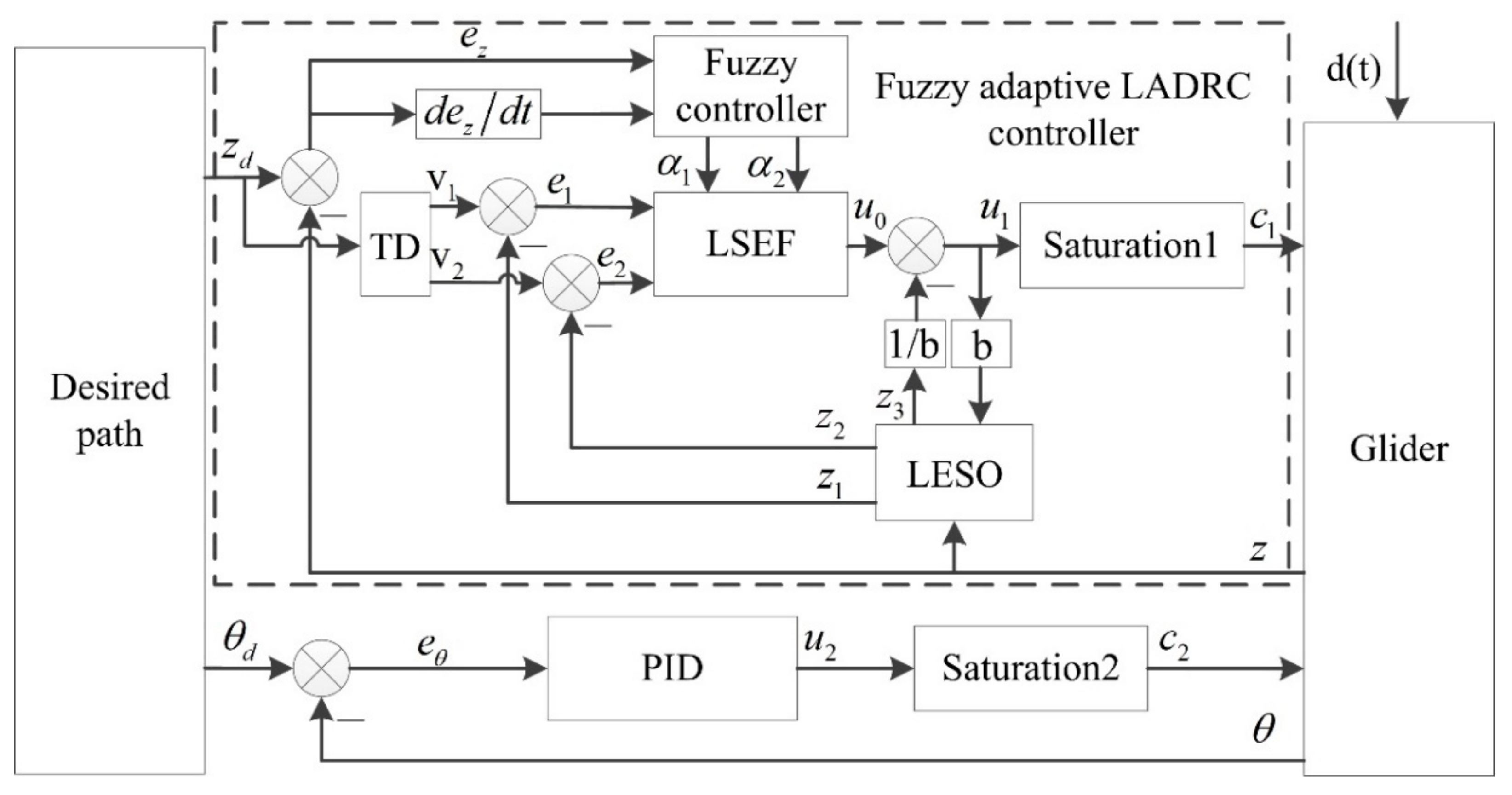
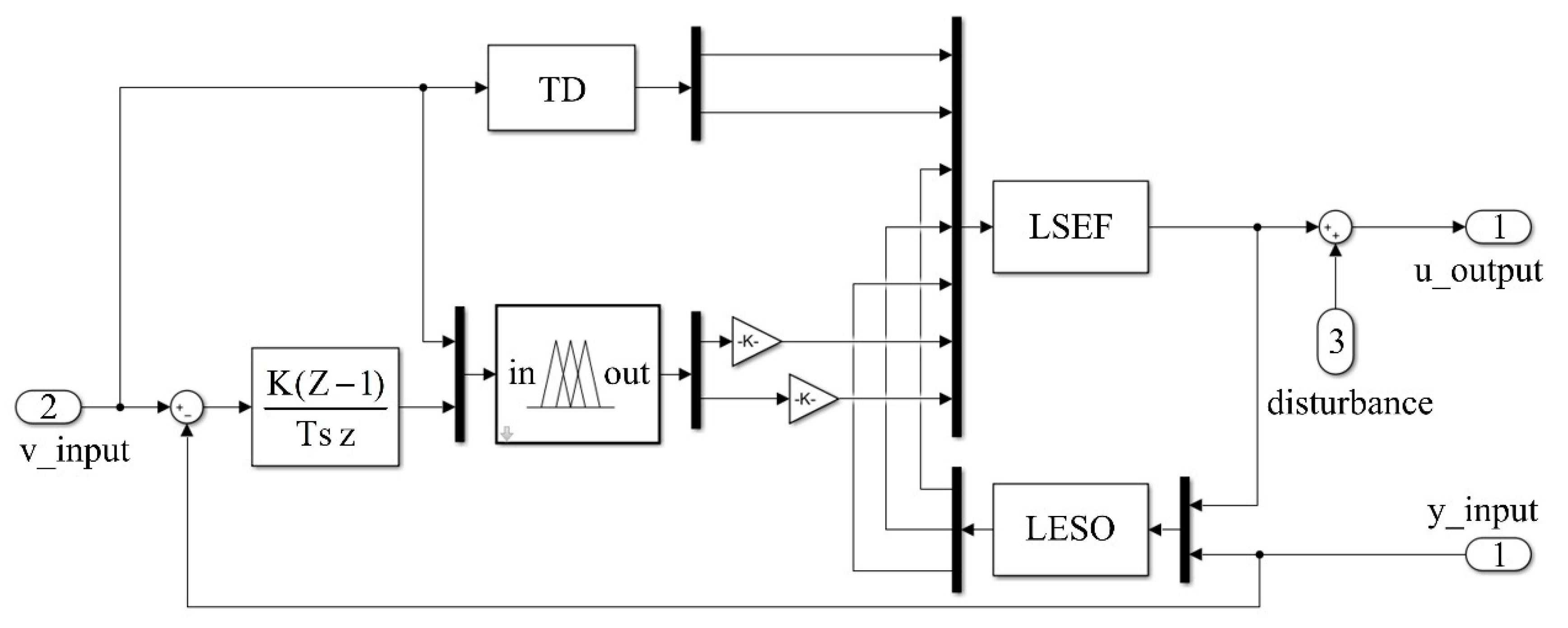
3.1. Fuzzy Adaptive LADRC Control Block Diagram

The underwater glider control system consists of path planning, fuzzy adaptive LADRC controller, the underwater glider dynamics model, etc., and its structure is shown in Figure 2.
Path planning mainly gives the expected values of the depth and attitude of the underwater glider. The fuzzy adaptive LADRC controller consists of four main parts: fuzzy controller, tracking differentiator (TD), linear extended state observer (LESO), and linear state error feedback control law (LSEF), through which the dive depth of the underwater glider is controlled. The classical PID controller is used to control the attitude of the underwater glider. d t is the external perturbation of the system. b is the control input coefficient. u i is the system control input. c i is the output after u i passing the input constraint (6).
c i = s a t u i = u i + ( u i > u i + ) u i u i u i u i + u i ( u i < u i )

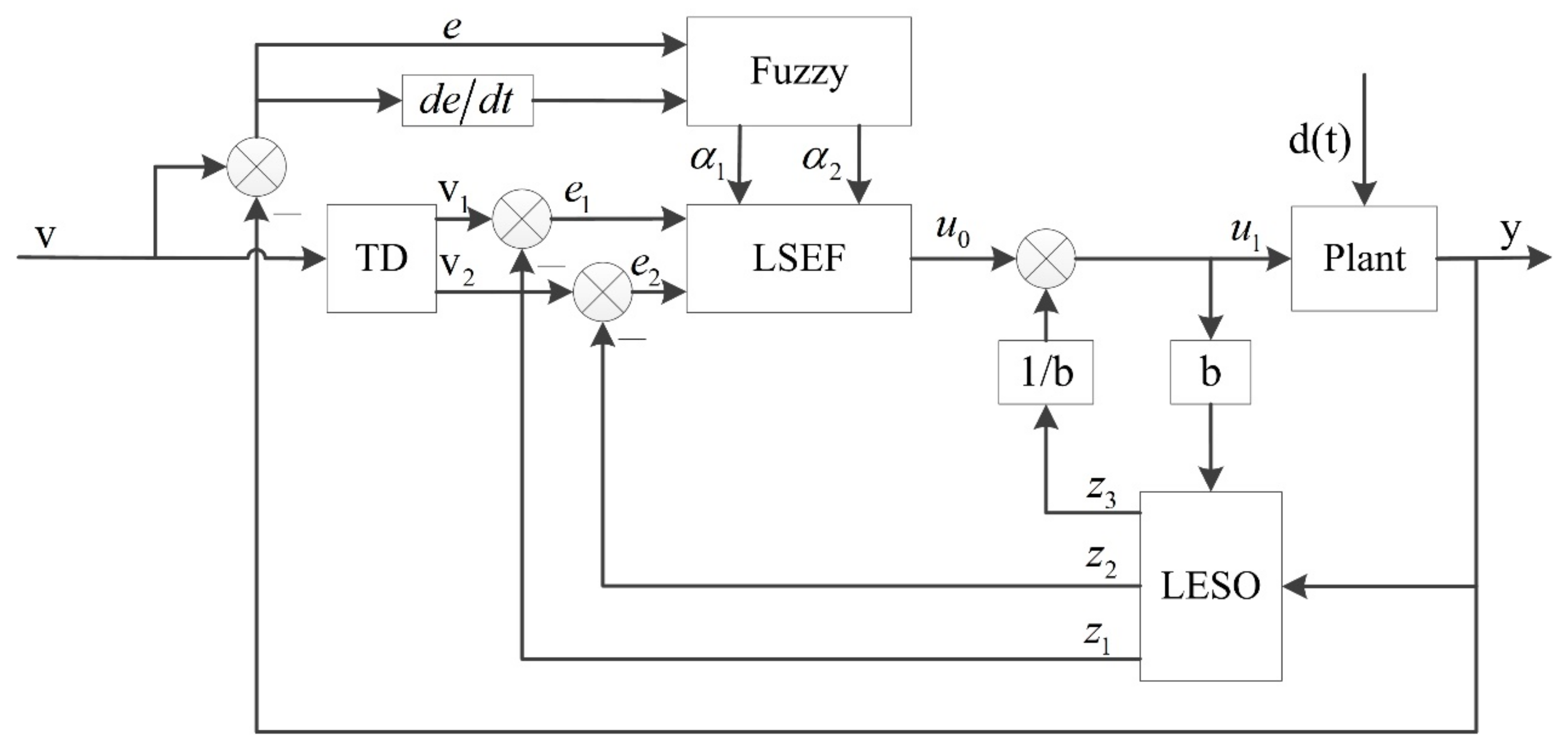
3.2. Fuzzy Adaptive LADRC Controller

Active Disturbance Rejection Control is a control method that observes the “sum of disturbances” of the system and compensates for them [27]. It uses an expansive state observer (ESO) to observe unmodeled dynamics, nonlinear dynamics, and external disturbances of the system to compensate for closed-loop systems. Although the traditional Active Disturbance Rejection Control method has advantages in terms of high accuracy and high feedback efficiency, it has too many selected parameters. The parameter rectification is tedious, and it is difficult to perform stability and other index analysis in engineering. Therefore, the LADRC method is proposed by Gao Zhiqiang et al. [28,29]. LADRC has the advantages of excellent control performance, fewer controller parameters, clear physical meaning, the small workload of parameter setting, etc., which is very convenient for theoretical analysis and can meet the needs of engineering applications. In this paper, the principle of fuzzy control is introduced on the basis of the LADRC method, and the parameters of LADRC are adaptively adjusted online to enhance its control performance and anti-interference capability. The structure of the fuzzy adaptive LADRC controller is shown in Figure 3.
The steps of making the fuzzy adaptive LADRC controller are described as follows.
  • Construction of the control structure;
  • Estimating the value of b and set other LADRC parameters;
  • Finding out the variation laws of e, ec and α 1 , α 2 according to the engineering practice, where ec is the differential value of the diving depth error e of the underwater glider;
  • Design the fuzzy membership function and establish the fuzzy law.

3.2.1. LADRC Controller

The LADRC controller mainly consists of three parts: the tracking differentiator TD, the linear extended state observer LESO, and the linear state error feedback control law (LSEF). The TD, LESO, and LSEF are designed for the underwater glider depth control problem, and the discrete form of the LADRC control algorithm is given.
The tracking differentiator TD is designed to smooth the required reference v , where v is used as the reference input to TD to obtain v 1 and the transition value v 2 of v .
v 1 k + 1 = v 1 k + h v 2 k v 2 k + 1 = v 2 k + h f h a n v 1 k v k , v 2 k , r , h f h a n v 1 k v k , v 2 k , r , h = r s i g n a , a > d r a d , a d d = r h d 0 = h d y = v 1 k ν k + h v 2 k a 0 = d 2 + 8 r y a = v 2 k + a 0 d 2 s i g n y , y > d 0 v 2 k + y h , y d 0
where r is the fast coefficient of TD, h is the sampling period of the control system, and f h a n is a nonlinear function.
The linear extended state observer is designed to estimate the system state. Among them, the total disturbances include unmodeled dynamics, internal and external disturbances, etc.
e 0 k = Z 1 k y k Z 1 k + 1 = Z 1 k + h Z 2 k β 1 e 0 k Z 2 k + 1 = Z 2 k + h Z 3 k β 2 e 0 k + b u k Z 3 k + 1 = Z 3 k h β 3 e 0 k
where e 0 is the position estimation error, Z 1 is the estimation of position, Z 2 is the estimation of velocity, and β 1 , β 2 , β 3 is a set of parameters to be determined. In order to ensure satisfactory estimation accuracy, according to the design principle of high gain state observer, β 1 , β 2 , β 3 can be designed so that it is generally larger than the upper bound of noise or disturbance. Based on the practical experience, as β 1 is smaller, the system regulation time is longer; β 2 should be larger than β 1 but not too large; and as β 3 is larger, the system overshoots more severely. Depending on the requirements of the system bandwidth or the online setup, there is generally a large range of adaptation, so it is not difficult to adjust the parameters β 1 , β 2 , and β 3 [30,31].
Z 3 is an estimate of the total disturbance, and the compensation process can reduce or even eliminate the effect of time-varying disturbances on the system performance.
Linear state error feedback:
e 1 k = v 1 k Z 1 k e 2 k = v 2 k Z 2 k u 0 k = α 1 e 1 k + α 2 e 2 k u k = u 0 k Z 3 k / b
where α 1 , α 2 are controller gain variables, b is the error feedback control variable, and u is the control input of the underwater glider system.

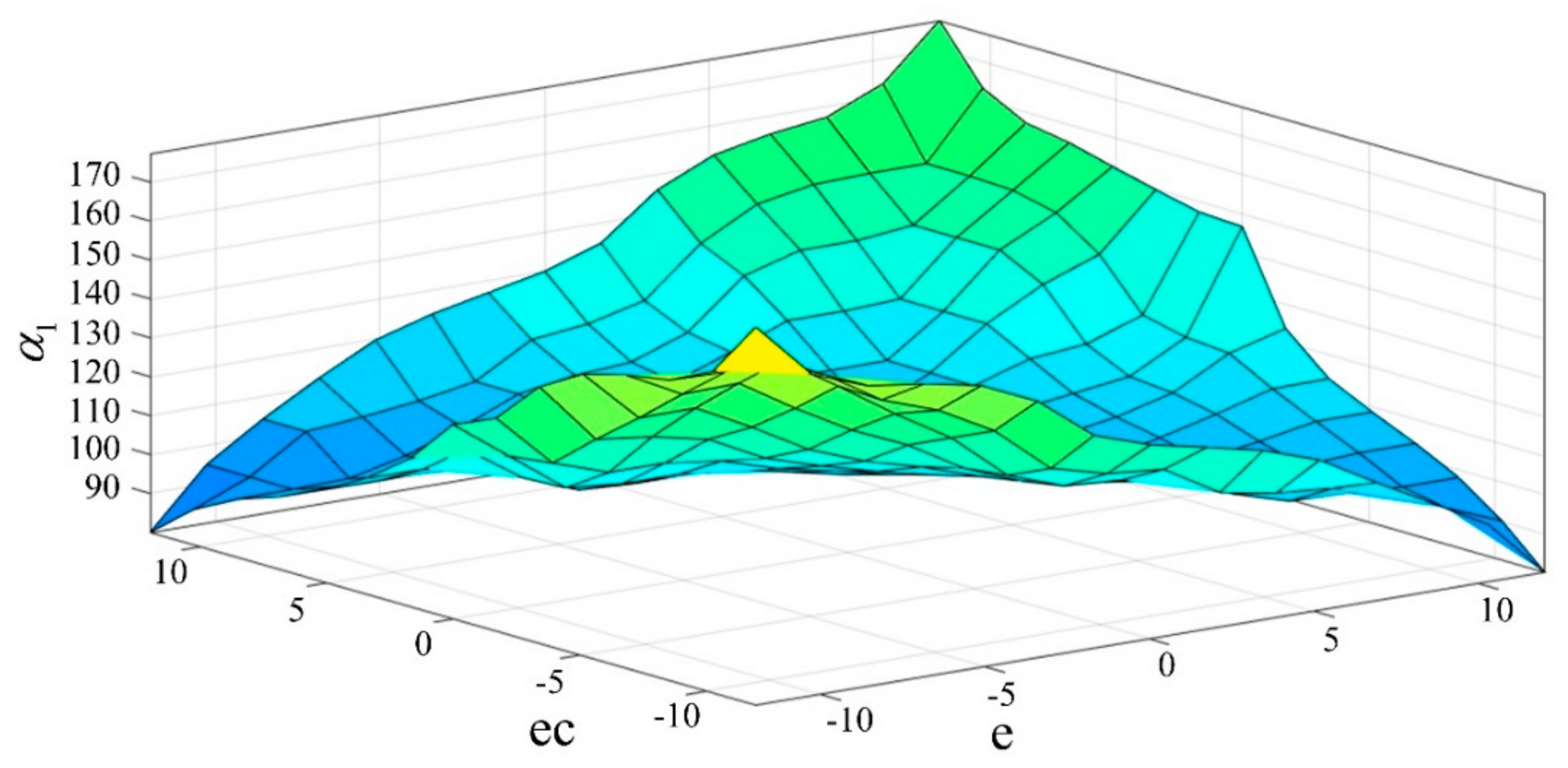
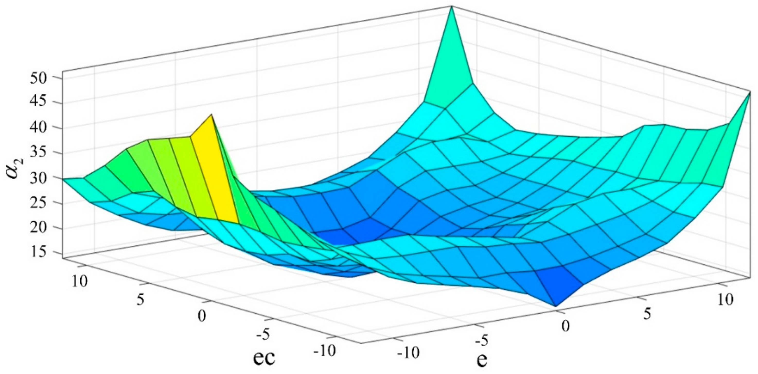
3.2.2. Design of Fuzzy Controller

The fuzzy control strategy has two inputs: the underwater glider dive depth error e and the differential value ec of the dive depth error e. The outputs are the parameter values of LADRC α 1 and α 2 . The affiliation functions of the input variables are defined by NB, NM, NS, ZO, PS, PM, and PB. The affiliation functions of the output variables are defined by ZO, PS, PM, and PB. In addition, e and ec determine the unique α 1 and α 2 by the fuzzy control rules.
Fuzzy control rules are the core of fuzzy controller design, and we combined engineering practice and LADRC control theory to develop the following fuzzy control rules.
  • When the deviation |e| is large, the system is in the rising stage, and in order to improve the system response speed, it should take a larger α 1 . Meanwhile, |e| of the instantaneously large may lead to the differential oversaturation and make the control effect beyond the permitted range, so take a smaller α 2 ;
  • When the control system is in normal operation, |e| and |ec| are medium, and in order to make the depth with a small overshoot, α 1 should be taken smaller. At this time, the value of the α 2 impact on the system is larger, should take a smaller value;
  • When |e| is small, α 1 should be increased appropriately so that the system has good steady-state performance. In order to prevent the system from oscillation near the set value, while taking into account the performance of the system against interference, the value α 2 must be properly selected, as α 2 is mainly based on |ec| to regulate; when |ec| larger, choose a smaller α 2 , and vice versa to take a larger α 2 .
According to the above regulation experience, combined with the regulation characteristics of the buoyancy of the underwater glider, the fuzzy control rules table of α 1 , α 2 can be established, respectively, as shown in Table 1 and Table 2.
The mapping of the relationship between fuzzy control inputs e, ec and outputs α 1 , α 2 are shown in Figure 4 and Figure 5, respectively.

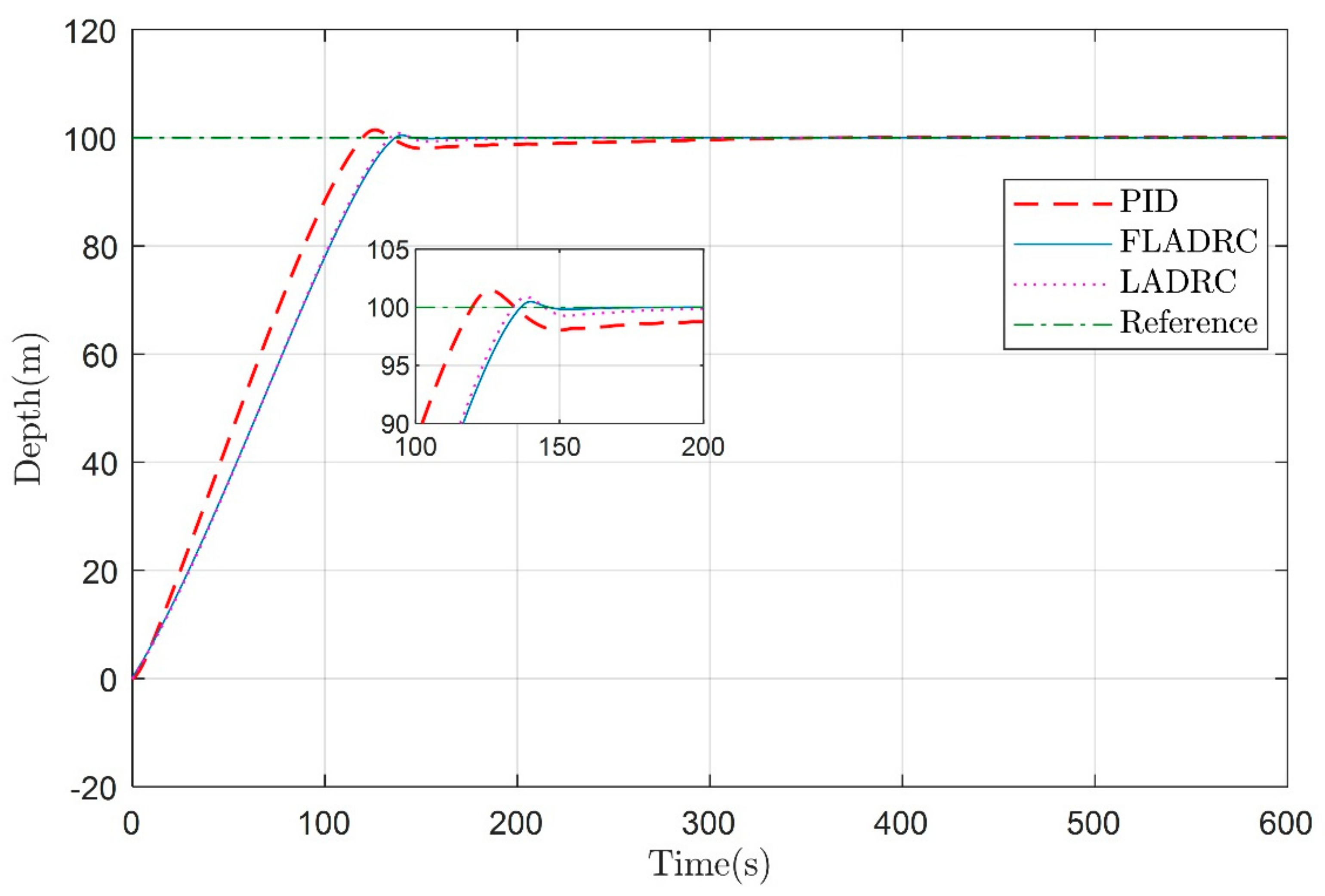
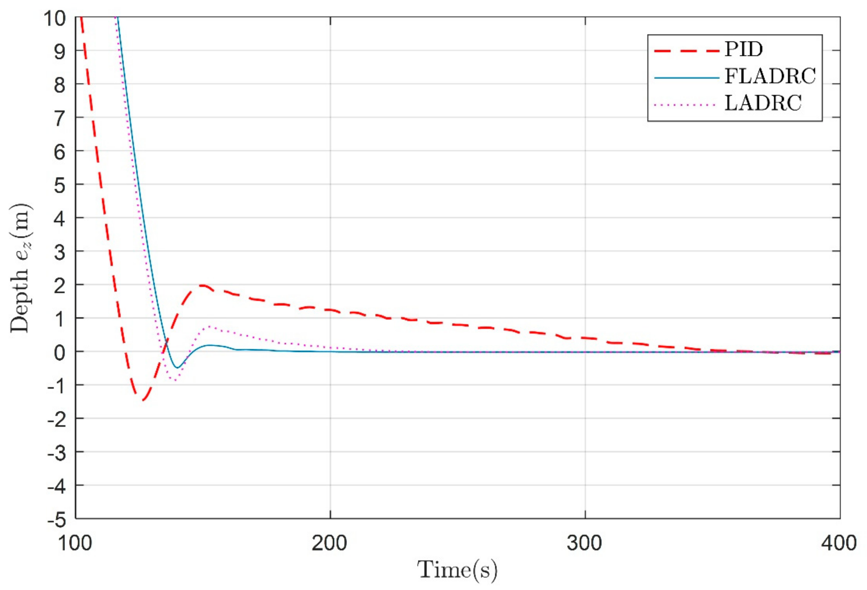
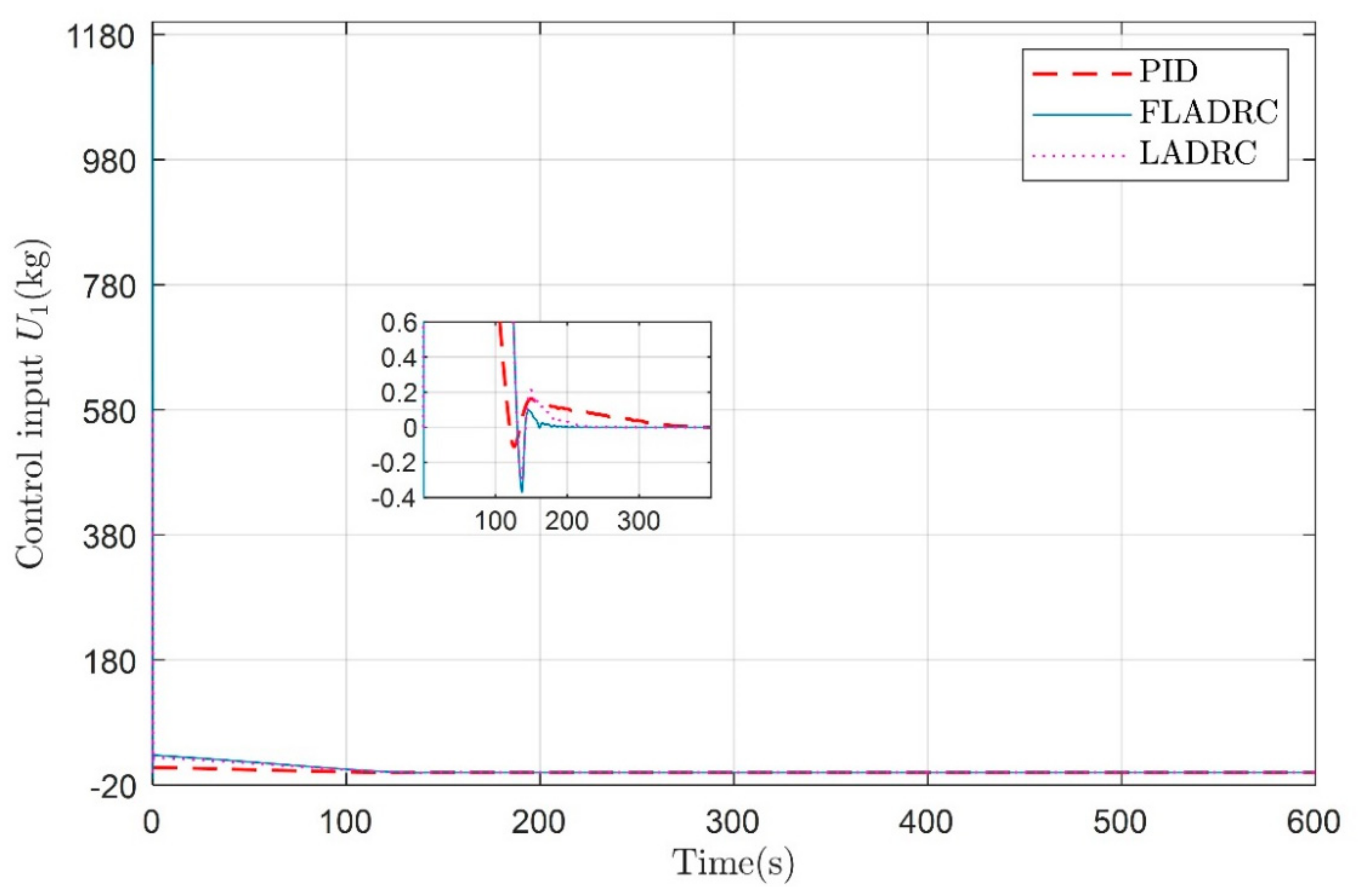
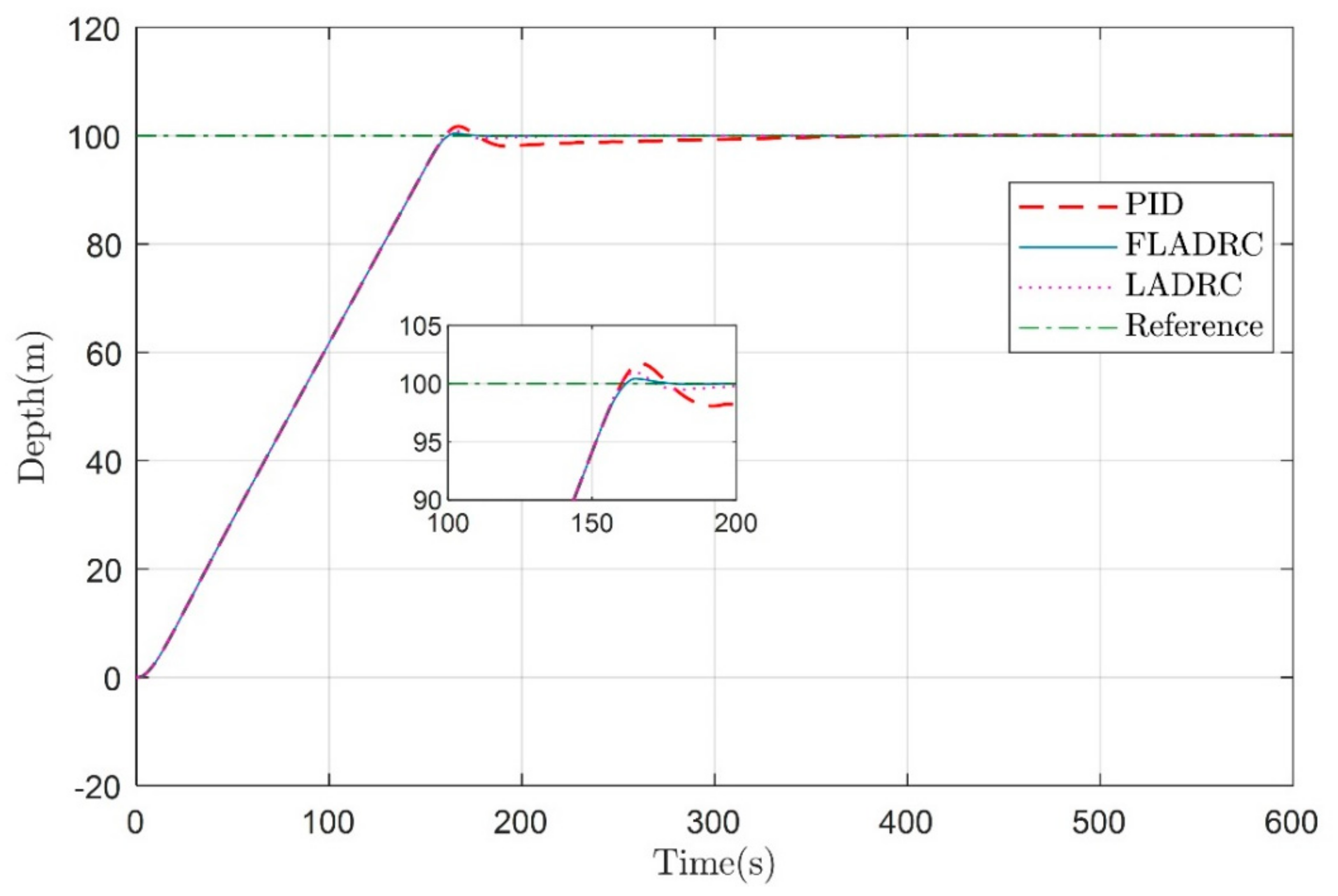
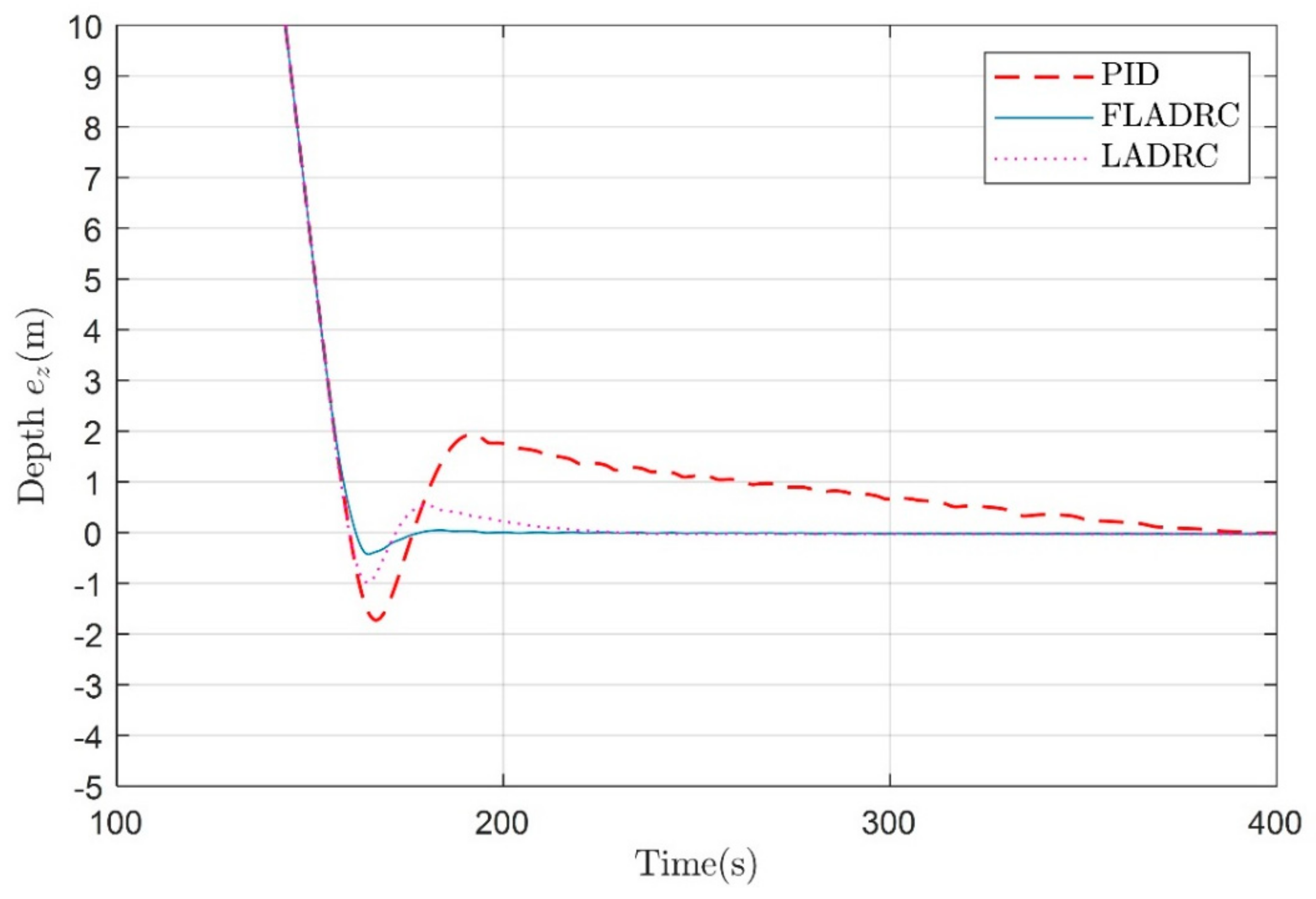
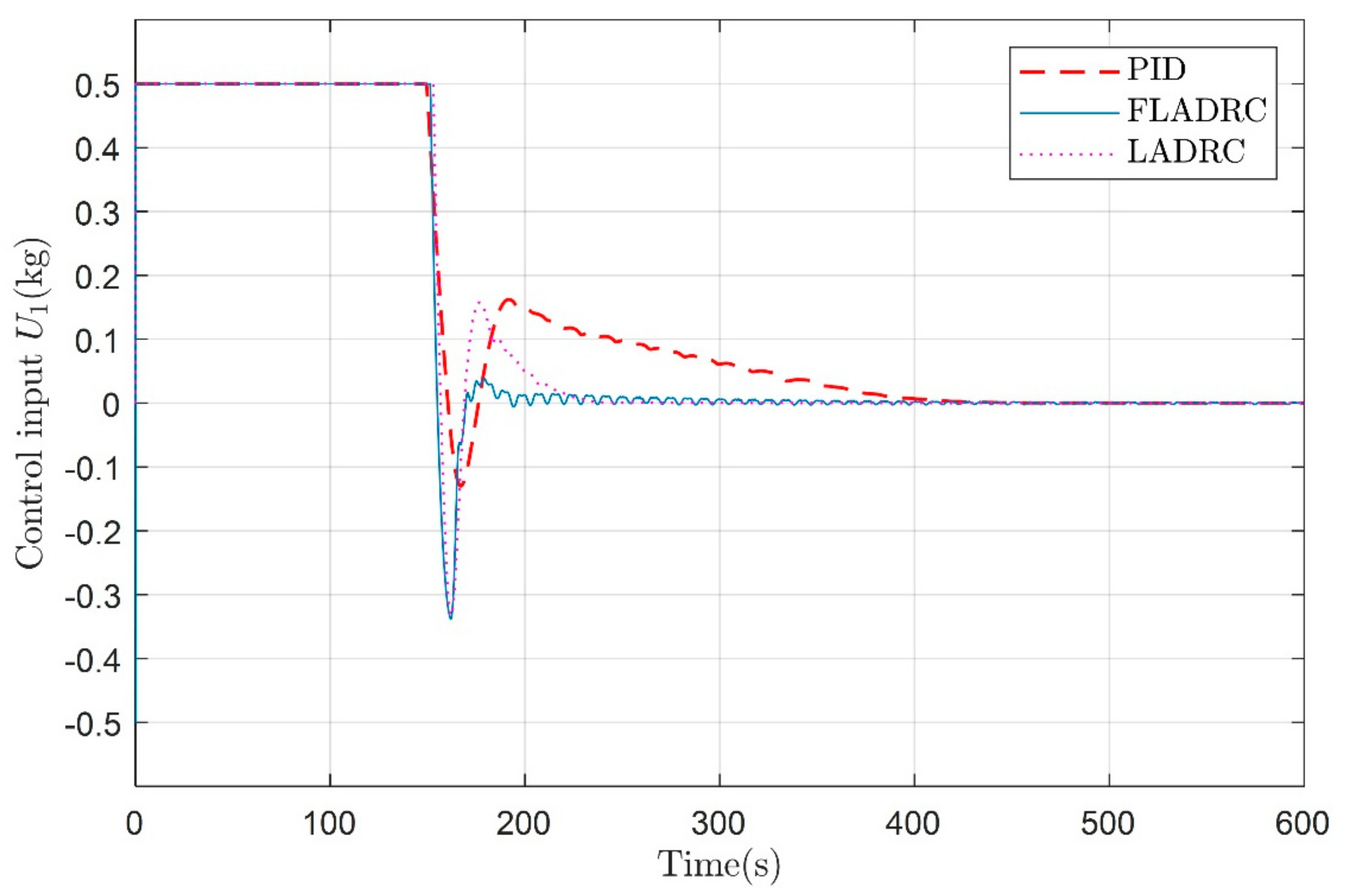
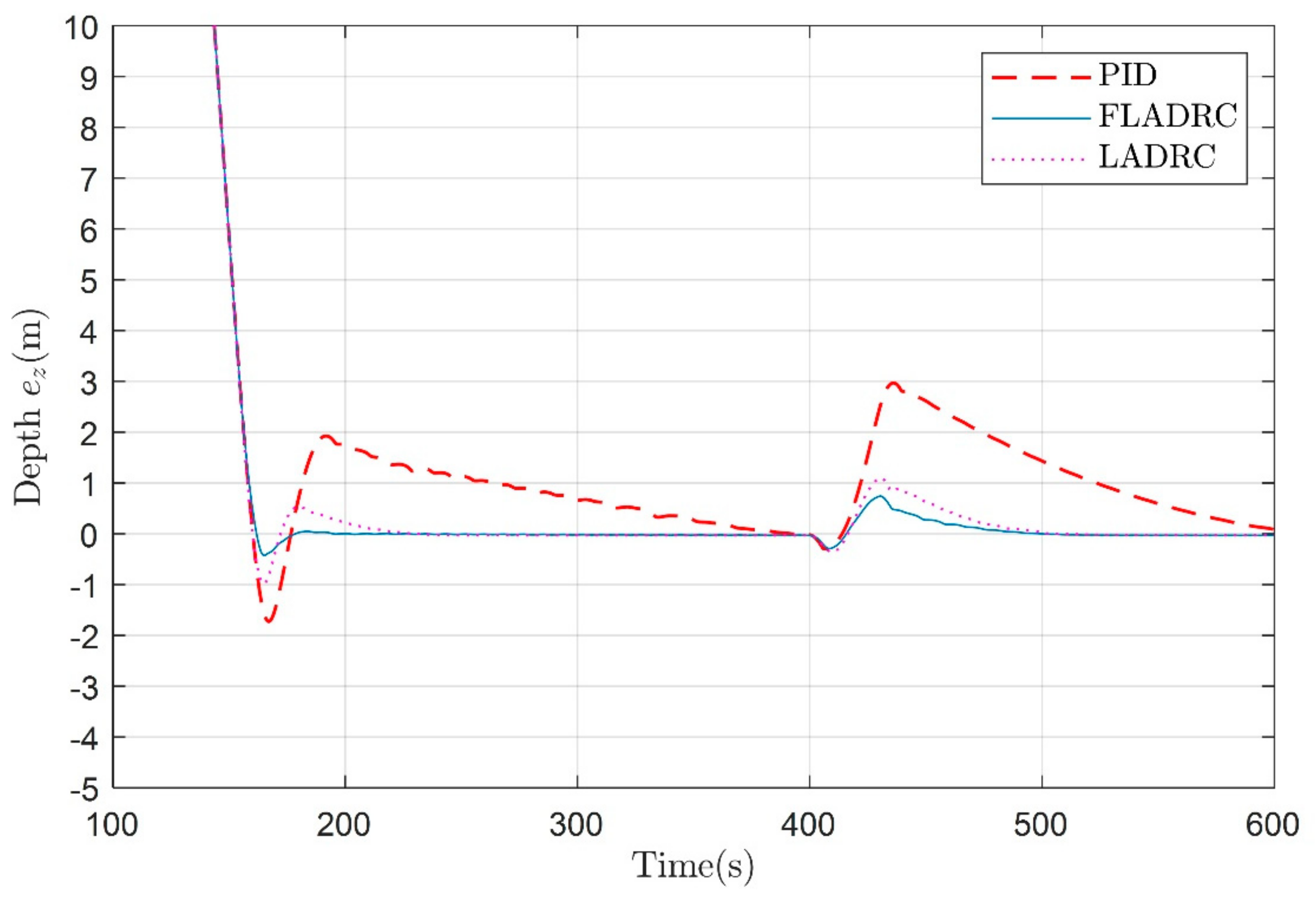
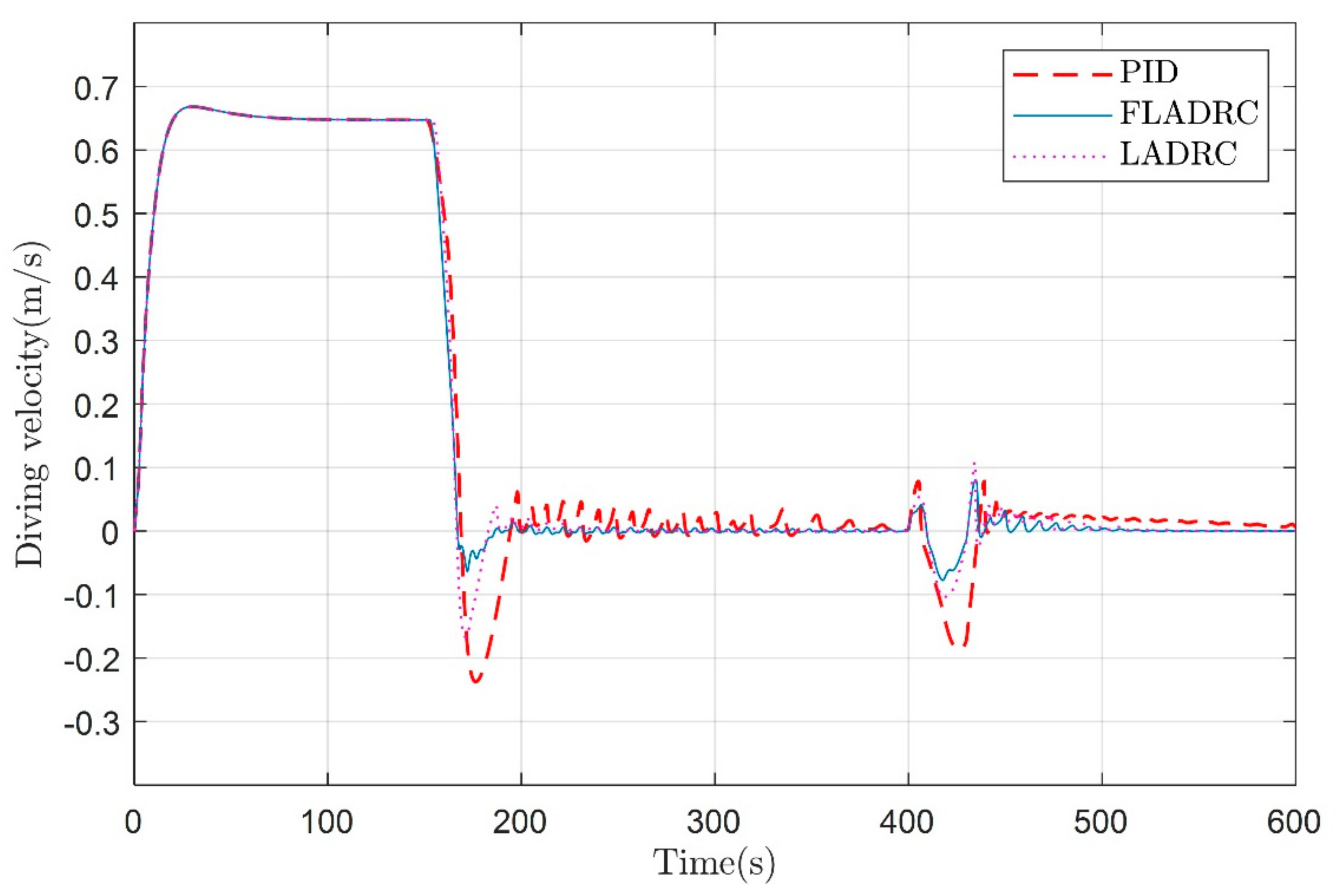
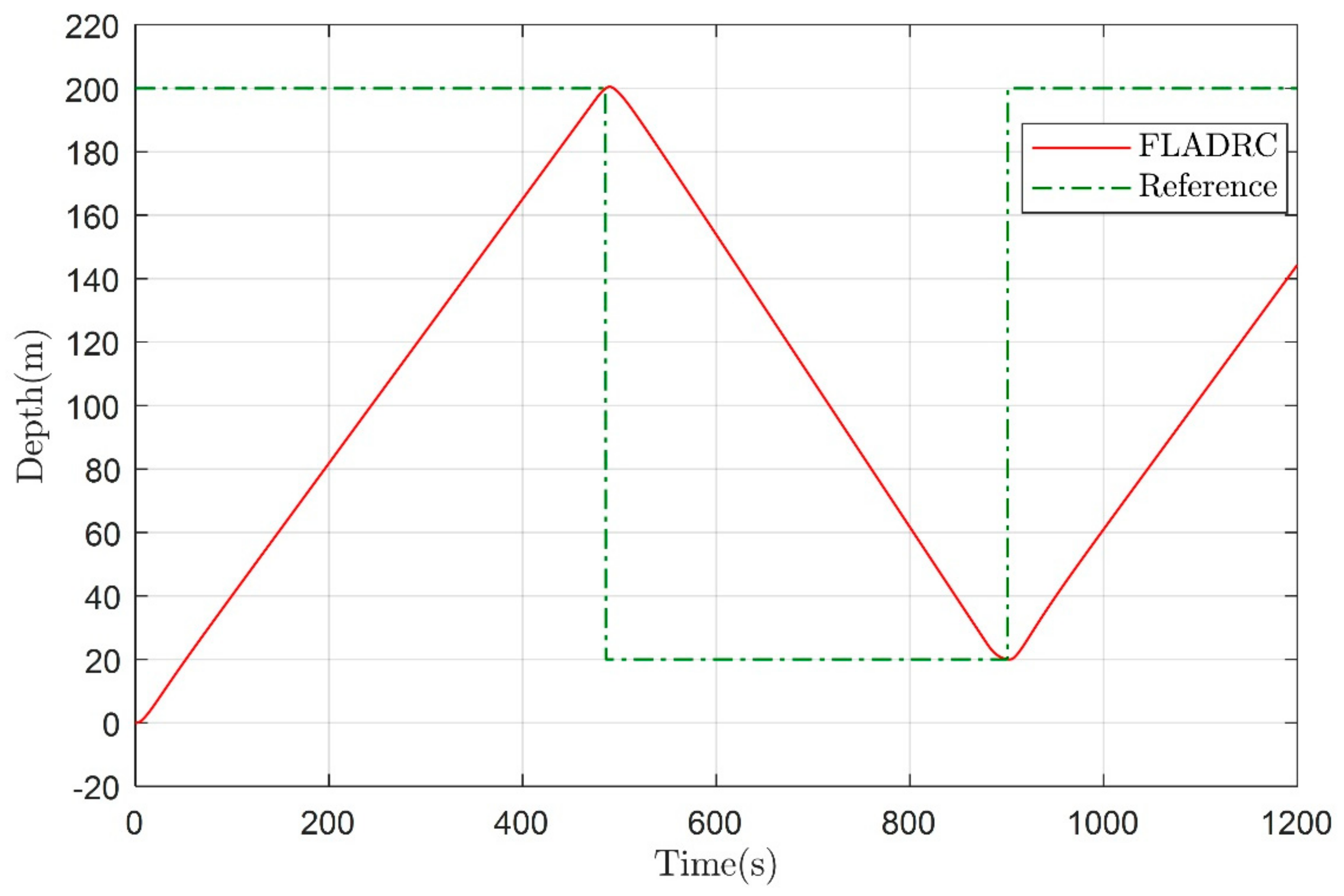
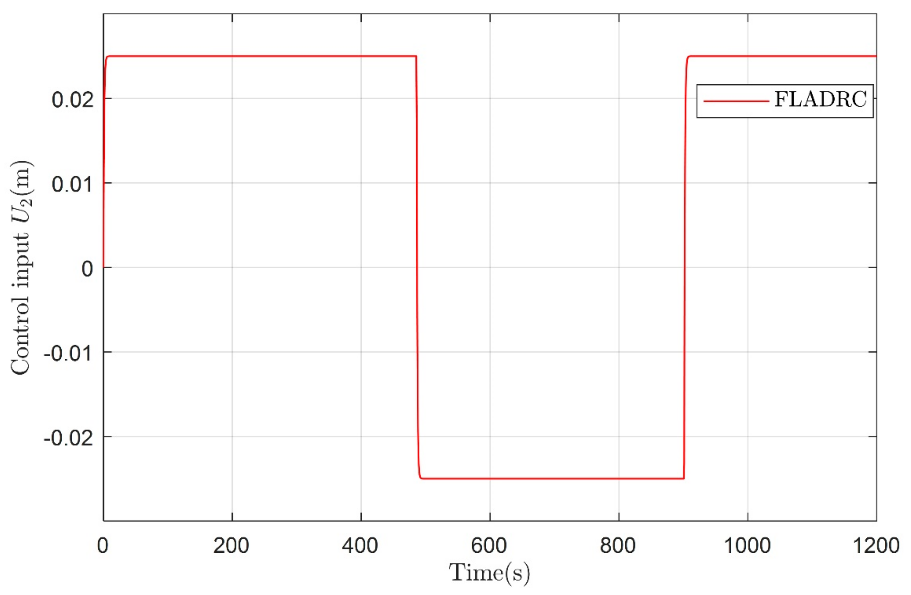
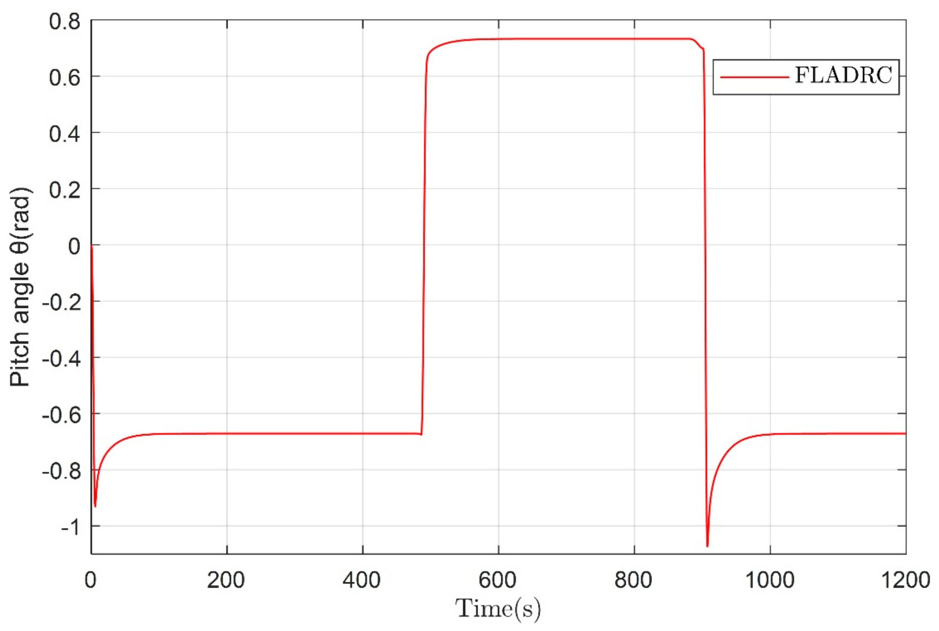
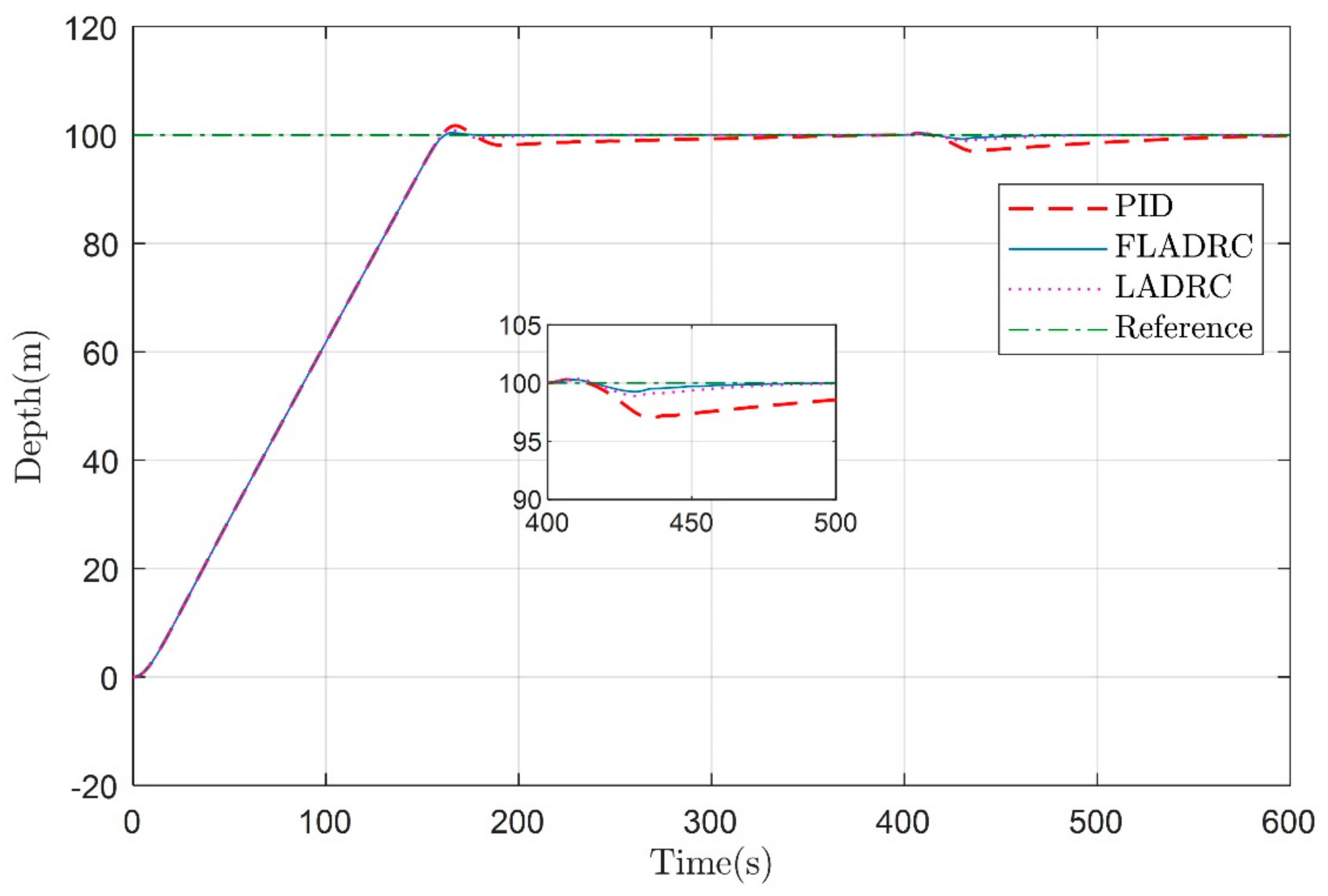
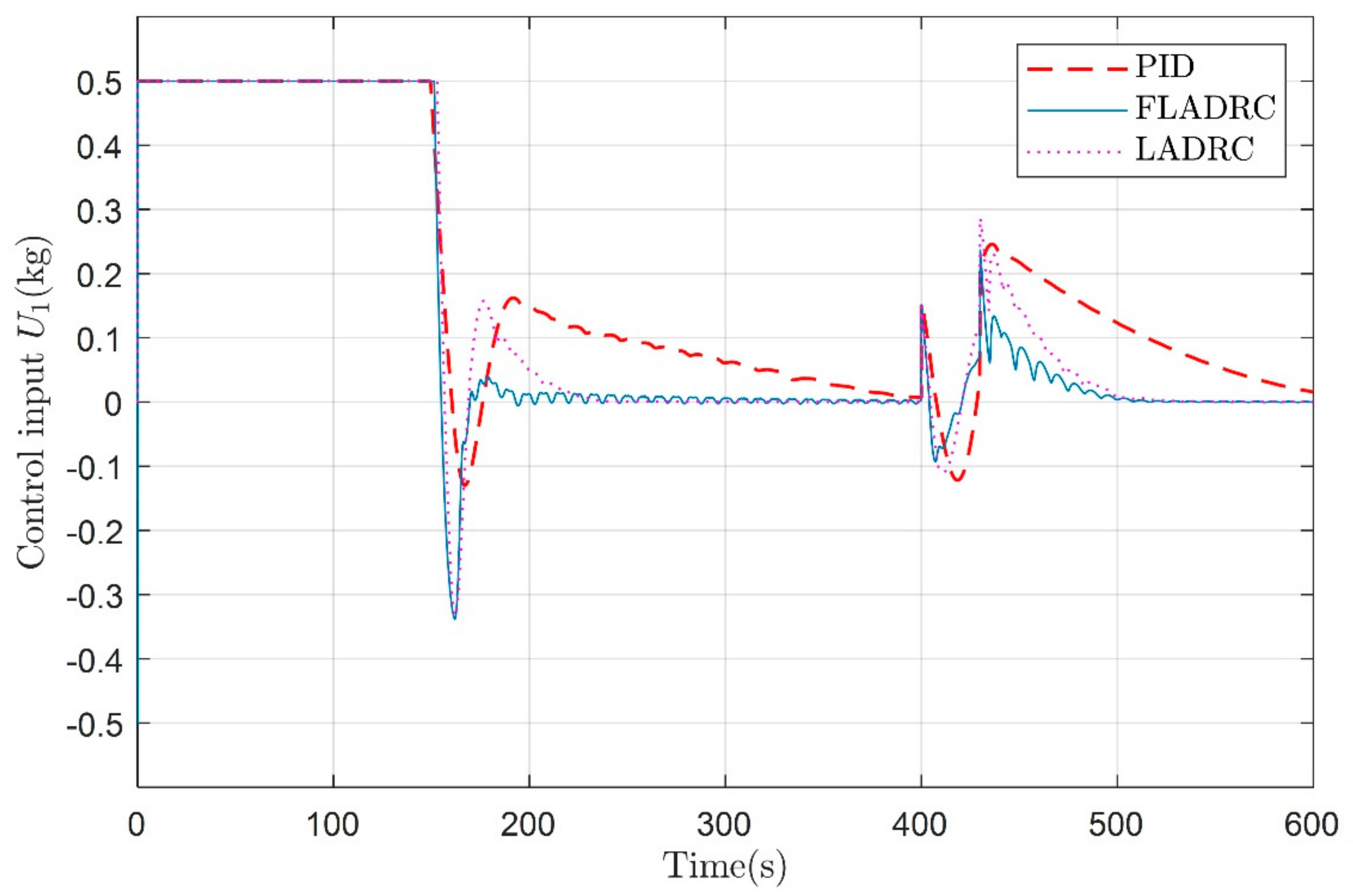
4. Simulation and Results Analysis

The fuzzy adaptive LADRC controller structure constructed in MATLAB/Simulink environment based on Figure 3 is shown in Figure 6. In this paper, a control structure based on the fusion of fuzzy and LADRC is proposed. The novelty of this structure is that the variation law of LADRC parameters is established by using fuzzy theory, which limits the stability time and stability overshoot of the system.
In this section, the performance of the fuzzy adaptive LADRC algorithm is illustrated by simulations based on the Sea-Wing underwater glider model [25]. The main geometric parameters and hydrodynamic coefficients of the underwater glider are shown in Table 3. In addition, the consolidated table of abbreviations and variable definitions is provided in Appendix A.
Three cases of vertical profile diving and floating motion of the underwater glider are considered in the MATLAB/Simulink simulation platform: (1) diving to a predetermined depth without strict input constraints, (2) diving to a predetermined depth with strict input constraints, and (3) diving to a predetermined depth with strict input constraints and external perturbations.
The parameters of the PID, LADRC and fuzzy adaptive LADRC algorithm are selected identically in these three stages, where the parameters of the LADRC and fuzzy adaptive LADRC algorithm are designed as shown in Table 4. The parameters of the PID control are designed as Kp = 0.08 and Ki = 1.0 × 10 6 . The control performance is compared using the conventional PID, LADRC controller with the proposed fuzzy adaptive LADRC controller.
Before the simulation starts, we find the control input U 2 corresponding to θ = 1 rad by the PID algorithm. Due to the time delay of the attitude control system of the underwater glider, a first-order inertia element is utilized to prevent a U 2 that is too steep. In this way, the uncertain factors caused by the parameter adjustment of attitude control PID algorithm can be eliminated. Therefore, we are able to focus more on verifying the control effect of our proposed algorithm.
In the first stage, the underwater glider was controlled to dive 100 m at a predetermined attitude angle θ = −1 rad without strict input constraints. As shown in Figure 7 and Figure 8, the PID algorithm has a faster convergence rate, greater overshoot, and takes longer to reach the predetermined depth. In contrast, the LADRC and fuzzy adaptive LADRC produce smaller overshoots and need a shorter time to reach the predetermined depth. In addition, they both can converge to the desired depth. However, as shown in Figure 9, in the absence of input constraints, the controller generates control inputs that clearly do not match the reality of the physical system to obtain a faster response.
In the second stage, the dive with strict input constraints reaches the predetermined depth. In order to verify the underwater glider’s performance of constant depth control under strict input constraints, the underwater glider was made to dive 100 m with a predetermined attitude angle θ = −1 rad, as shown in Figure 10. The control inputs are limited, U 1 + = 0.5 kg, U 1 = −0.5 kg and U 2 + = 0.05 m, U 2 = −0.05 m.
In Figure 10 and Figure 11, the convergence rates of the PID, LADRC, and fuzzy adaptive LADRC algorithms are essentially the same, with the PID overshoot being larger and taking longer to reach a predetermined depth. It takes about 399.67 s, 226.27 s, and 195.23 s, respectively, for PID, LADRC, and fuzzy adaptive LADRC to make the underwater glider converge to the target depth. In contrast, the fuzzy adaptive LADRC produces less overshoot and takes the shortest time to reach the predetermined depth. In addition to similar performance to that of the first stage, comparing Figure 7 and Figure 10 and Figure 8 and Figure 11 show the degradation of control performance due to input constraints. It can be seen that under the strict input constraint, the underwater glider takes a longer time to reach the predetermined depth, but the overshoot is relatively small. In this case, the maximum overshoot of the PID, LADRC, and fuzzy adaptive LADRC is 1.73 m, 0.99 m, and 0.43 m, respectively. Meanwhile, the relevant control inputs are shown in Figure 12.
In the third stage, the dive is performed under strict input constraints and external perturbations to reach the predetermined depth. To verify the immunity performance of the system, an external disturbance d(t) = 0.2sin(0.1(t − 400)) was applied to the underwater glider dynamics at t = 400 s and lasted for the 30 s. The control input is also limited, U 1 + = 0.5 kg, U 1 = −0.5 kg and U 2 + = 0.05 m, U 2 = −0.05 m. As shown in Figure 13 and Figure 14, the fuzzy adaptive LADRC controller has better anti-disturbance performance compared to the PID and LADRC controller when the external disturbance starts at t = 400 s.
The control input and the diving velocity of the glider are shown in Figure 15 and Figure 16, respectively. The fuzzy adaptive LADRC controller given in the paper can also control the underwater glider well for sawtooth motion, as shown in Figure 17. The control inputs of the sawtooth trajectory and the change of pitch angle are shown in Figure 18 and Figure 19, respectively.
In cases 2 and 3, when the underwater glider was controlled to dive 100 m at a predetermined attitude angle θ = −1 rad, the maximum overshoot of FLADRC is reduced by 75.1% and 56.6% relative to PID and LADRC, respectively, as shown in Table 5. The comprehensive comparison results demonstrate that the fuzzy adaptive LADRC controller can guarantee satisfactory control performance even in the presence of model uncertainty, unknown time-varying disturbances, and input constraints.

5. Conclusions

This paper focuses on the controller that helps the underwater glider precisely reach a predetermined depth or float at a specific depth. A fuzzy adaptive LADRC controller is proposed to effectively address the challenges of underwater glider models’ uncertainty and time-varying external disturbances. It uses the fuzzy control principle to adjust the parameters of LADRC online, improving the response speed, reducing oscillation and overshoot, and enhancing the robustness of the system. The parameter tuning of the controller is completed according to the actual experience. The stability of the closed-loop system is verified by extensive simulation, and the stability of the proposed closed-loop control system is good. The performance of the controller is compared with the traditional PID and LADRC controller. Particularly, when the underwater glider was controlled to dive 100 m at a predetermined attitude angle θ = −1 rad, the maximum overshoot of FLADRC is reduced by 75.1% and 56.6% relative to PID and LADRC, respectively. The fuzzy adaptive LADRC controller also has the advantages of good stability, short rectification time, and robustness.
In the future, the application of the fuzzy adaptive LADRC controller for attitude transition control of underwater gliders is being prepared. Finally, it will be validated on a prototype vehicle.

Author Contributions

Conceptualization, Z.W. and B.Y.; methodology, Z.W.; formal analysis, Z.W. and C.Y.; investigation, Z.W.; data curation, Z.W. and M.L.; writing—original draft preparation, Z.W.; writing—review and editing, C.Y. and M.L.; visualization, Z.W.; supervision, B.Y. and L.L.; project administration, L.L. All authors have read and agreed to the published version of the manuscript.

Funding

The work presented in this paper is financially supported by the Key Laboratory of Science and Technology on Underwater Acoustic Antagonizing (grant number JCKY2020207CH03), the project of the Shanghai Committee of Science and Technology (grant number 20dz1206600), China Postdoctoral Science Foundation (grant number 2020M681286), and the National Natural Science Foundation of China (grant number 41527901).

Institutional Review Board Statement

Not applicable.

Informed Consent Statement

Not applicable.

Data Availability Statement

Not applicable.

Conflicts of Interest

The authors declare no conflict of interest.

Appendix A

Table A1. Consolidated table of abbreviations and variable definitions.
Abbreviations and VariableDefinition
PIDProportion integral differential
ADRCActive disturbance rejection control
LADRCLinear active disturbance rejection control
FLADRCFuzzy adaptive linear active disturbance rejection control
TDTracking differentiator
LSEFLinear state error feedback
LESOLinear extended state observer
LQRLinear quadratic regulator
DSMCDynamic sliding mode control
b = [ x , y , z ] T Position of the origin of the body coordinate system
ϕ Cross-roll angle
θ Pitch angle
ψ Yaw angle
V = [ u , v , w ] T Linear velocity in the body coordinate system
p , q , r Angular velocity in the body coordinate system
α Attack angle
βSideslip angle
M f 1 , M f 2 , M f 3 Added mass
I f 1 , I f 2 , I f 3 Added moment of inertia
K M R ,   K M 0 ,   K p ,     K M ,     K q ,   K M Y ,   K r , K D 0 ,   K L 0 ,     K β ,   K L Hydrodynamic coefficients
m b Mass of the adjustable net buoyancy
m p Mass of the movable block
m r b Mass of the underwater glider shell
R p Offset of the movable block
γ Rotation angle of the movable block
r b 1 The position of the variable ballast mass on the e 1 -axis of the body coordinate system
r p 1 Position of the movable block in the body coordinate system
U 1 Mass of pump oil to adjust the net buoyancy
U 2 Position of the moving mass

References

  1. Yu, C.; Liu, C.; Lian, L.; Xiang, X.; Zeng, Z. ELOS-based path following control for underactuated surface vehicles with actuator dynamics. Ocean Eng. 2019, 187, 106139. [Google Scholar] [CrossRef]
  2. Jawhar, I.; Mohamed, N.; Al-Jaroodi, J.; Zhang, S. An Architecture for Using Autonomous Underwater Vehicles in Wireless Sensor Networks for Underwater Pipeline Monitoring. IEEE Trans. Ind. Inform. 2019, 15, 1329–1340. [Google Scholar] [CrossRef]
  3. Cho, H.; Jeong, S.-K.; Ji, D.-H.; Tran, N.-H.; Vu, M.T.; Choi, H.-S. Study on Control System of Integrated Unmanned Surface Vehicle and Underwater Vehicle. Sensors 2020, 20, 2633. [Google Scholar] [CrossRef] [PubMed]
  4. Davis, R.E.; Eriksen, C.C.; Jones, C.P. Autonomous buoyancy-driven underwater gliders. In Technology and Applications of Autonomous Underwater Vehicles; Taylor and Francis: London, UK, 2002; pp. 37–58. [Google Scholar]
  5. Tian, X.; Zhang, H.; Zhang, L.; Wang, Y.; Yang, Y. Research on positive buoyancy underwater glider and its sailing efficiency. Appl. Ocean Res. 2021, 110, 102592. [Google Scholar] [CrossRef]
  6. Edwards, D.; Arnold, N.; Heinzen, S.; Strem, C.; Young, T. Flying emplacement of an underwater glider. In Proceedings of the OCEANS 2017-Anchorage, Anchorage, AK, USA, 18–21 September 2017; pp. 1–6. [Google Scholar]
  7. Imlach, J.; Mahr, R. Modification of a military grade glider for coastal scientific applications. In Proceedings of the 2012 Oceans, Hampton Roads, VA, USA, 14–19 October 2012; pp. 1–6. [Google Scholar]
  8. Castelao, R.; Glenn, S.; Schofield, O.; Chant, R.; Wilkin, J.; Kohut, J. Seasonal evolution of hydrographic fields in the central middle atlantic bight from glider observations. Geophys. Res. Lett. 2008, 35, 183–199. [Google Scholar] [CrossRef]
  9. Daniel, L.R.; Sylvia, T.C. On sampling the ocean using underwater gliders. J. Geophys. Res. Ocean. 2011, 116, C08010. [Google Scholar]
  10. Webb, D.; Simonetti, P.; Jones, C. SLOCUM: An underwater glider propelled by environmental energy. IEEE J. Ocean. Eng. 2001, 26, 447–452. [Google Scholar] [CrossRef]
  11. Sherman, J.; Davis, R.; Owens, W.; Valdes, J. The autonomous underwater glider “spray”. IEEE J. Ocean. Eng. 2001, 26, 437–446. [Google Scholar] [CrossRef] [Green Version]
  12. Nakamura, M.; Asakawa, K.; Hyakudome, T.; Kishima, S.; Matsuoka, H.; Minami, T. Hydrodynamic Coefficients and Motion Simulations of Underwater Glider for Virtual Mooring. IEEE J. Ocean. Eng. 2013, 38, 581–597. [Google Scholar] [CrossRef] [Green Version]
  13. Yu, J.; Zhang, A.; Jin, W.; Chen, Q.; Tian, Y.; Liu, C. Development and Experiments of the Sea-Wing Underwater Glider. China Ocean Eng. 2011, 25, 721–736. [Google Scholar] [CrossRef] [Green Version]
  14. Liu, F.; Wang, Y.; Wu, Z.; Wang, S. Motion analysis and trials of the deep sea hybrid underwater glider Petrel-II. China Ocean. Eng. 2017, 31, 55–62. [Google Scholar] [CrossRef]
  15. Leonard, N.E.; Graver, J.G. Model-based feedback control of autonomous underwater gliders. Ocean. Eng. 2001, 26, 633–645. [Google Scholar] [CrossRef] [Green Version]
  16. Fan, S. Dynamics Modeling, Motion Analysis and Controller Design of Underwater Gliders under the Influence of Ocean Currents; Zhejiang University: Hangzhou, China, 2013. [Google Scholar]
  17. Huang, Z.; Zheng, H.; Wang, S.; Ma, J.; Liu, Y. A self-searching optimal ADRC for the pitch angle control of an underwater thermal glider in the vertical plane motion. Ocean Eng. 2018, 159, 98–111. [Google Scholar] [CrossRef]
  18. Zhou, H.; Wei, Z.; Zeng, Z.; Yu, C.; Yao, B.; Lian, L. Adaptive robust sliding mode control of autonomous underwater glider with input constraints for persistent virtual mooring. Appl. Ocean Res. 2020, 95, 102027. [Google Scholar] [CrossRef]
  19. Vu, M.T.; Le, T.-H.; Thanh, H.L.N.N.; Huynh, T.-T.; Van, M.; Hoang, Q.-D.; Do, T.D. Robust Position Control of an Over-actuated Underwater Vehicle under Model Uncertainties and Ocean Current Effects Using Dynamic Sliding Mode Surface and Optimal Allocation Control. Sensors 2021, 21, 747. [Google Scholar] [CrossRef]
  20. Xiang, X.; Yu, C.; Lapierre, L.; Zhang, J.; Zhang, Q. Survey on Fuzzy-Logic-Based Guidance and Control of Marine Surface Vehicles and Underwater Vehicles. Int. J. Fuzzy Syst. 2018, 20, 572–586. [Google Scholar] [CrossRef]
  21. Cao, J.; Cao, J.; Zeng, Z.; Lian, L. Nonlinear multiple-input-multiple-output adaptive backstepping control of underwater glider systems. Int. J. Adv. Robot. Syst. 2016, 13, 1729881416669484. [Google Scholar] [CrossRef] [Green Version]
  22. Xu, H.; Oliveira, P.; Soares, C.G. L1 adaptive backstepping control for path-following of underactuated marine surface ships. Eur. J. Control 2021, 58, 357–372. [Google Scholar] [CrossRef]
  23. Isa, K.; Arshad, M. Neural network control of buoyancy-driven autonomous underwater glider. In Recent Advances in Robotics and Automation; Springer: Berlin/Heidelberg, Germany, 2013. [Google Scholar]
  24. Sands, T. Development of Deterministic Artificial Intelligence for Unmanned Underwater Vehicles (UUV). J. Mar. Sci. Eng. 2020, 8, 578. [Google Scholar] [CrossRef]
  25. Zhang, S.; Yu, J.; Zhang, A.; Zhang, F. Spiraling motion of underwater gliders: Modeling, analysis, and experimental results. Ocean Eng. 2013, 60, 1–13. [Google Scholar] [CrossRef]
  26. Vu, M.T.; Van, M.; Bui, D.H.P.; Do, Q.T.; Huynh, T.-T.; Lee, S.-D.; Choi, H.-S. Study on Dynamic Behavior of Unmanned Surface Vehicle-Linked Unmanned Underwater Vehicle System for Underwater Exploration. Sensors 2020, 20, 1329. [Google Scholar] [CrossRef] [Green Version]
  27. Han, J. From PID to Active Disturbance Rejection Control. IEEE Trans. Ind. Electron. 2009, 56, 900–906. [Google Scholar] [CrossRef]
  28. Gao, Z.; Hu, S.; Jiang, F. A novel motion control design approach based on active disturbance rejection. In Proceedings of the 40th IEEE Conference on Decision and Control, Orlando, FL, USA, 4–7 December 2001; pp. 1547–1552. [Google Scholar]
  29. Gao, Z. Scaling and bandwidth-parameterization based controller tuning. In Proceedings of the 2003 American Control Conference, Denver, Colorado, 4–6 June 2003; pp. 4989–4996. [Google Scholar]
  30. Wang, Y.; Zhang, W.; Dong, H.; Yu, L. A LADRC based fuzzy PID approach to contour error control of networked motion control system with time arying delays. Asian J. Control 2019, 22, 1973–1985. [Google Scholar] [CrossRef]
  31. Li, H.; Liu, X.; Li, J. The research of fuzzy immune linear active disturbance rejection control strategy for three-motor synchronous system. Control Eng. Appl. Inform. 2015, 14, 50–58. [Google Scholar]
Figure 1. The coordinate system of the underwater glider.
Jmse 09 00698 g001
Figure 2. Block diagram of the underwater glider control system.
Jmse 09 00698 g002
Figure 3. Fuzzy adaptive LADRC controller.
Jmse 09 00698 g003
Figure 4. Fuzzy control input-output relationship mapping diagram of α 1 .
Jmse 09 00698 g004
Figure 5. Fuzzy control input-output relationship mapping diagram of α 2 .
Jmse 09 00698 g005
Figure 6. SIMULINK simulation block diagram of fuzzy adaptive LADRC control.
Jmse 09 00698 g006
Figure 7. Underwater glider diving to a fixed depth of 100 m in the vertical profile.
Jmse 09 00698 g007
Figure 8. Depth following errors under PID, FLADRC, and LADRC.
Jmse 09 00698 g008
Figure 9. Control input for a 100 m dive in the vertical profile.
Jmse 09 00698 g009
Figure 10. Underwater glider diving to a fixed depth of 100 m in the vertical profile under strict input constraint.
Jmse 09 00698 g010
Figure 11. Depth following errors under PID, FLADRC, and LADRC under strict input constraint.
Jmse 09 00698 g011
Figure 12. Control input for diving 100 m fixed depth in vertical profile under strict input constraint.
Jmse 09 00698 g012
Figure 13. Underwater glider diving to a fixed depth of 100 m in the vertical profile under external disturbances and strict input constraints.
Jmse 09 00698 g013
Figure 14. Depth following errors of PID, FLADRC, and LADRC under external disturbances and strict input constraints.
Jmse 09 00698 g014
Figure 15. Control input for a 100 m dive in the vertical profile under external disturbances and strict input constraints.
Jmse 09 00698 g015
Figure 16. The diving velocity of the glider in the vertical profile under external disturbances and strict input constraints.
Jmse 09 00698 g016
Figure 17. The sawtooth trajectory of the underwater glider.
Jmse 09 00698 g017
Figure 18. The sawtooth trajectory control input U 2 of the underwater glider.
Jmse 09 00698 g018
Figure 19. The variation of pitch angle for the sawtooth trajectory of the glider.
Jmse 09 00698 g019
Table 1. Fuzzy control rules of α 1 .
α1ecNBNMNSZOPSPMPB
e
NBPBPBPMPMPSZOZO
NMPBPBPMPSPSZOPS
NSPMPMPMPSZOPSPS
ZOPMPMPSZOPSPMPM
PSPSPSZOPSPSPMPM
PMPSZOPSPMPMPMPB
PBZOZOPMPMPMPBPB
Table 2. Fuzzy control rules of α 2 .
α2ecNBNMNSZOPSPMPB
e
NBPSPSPBPBPBPMPS
NMPSPSPBPMPMPSZO
NSZOPSPMPMPSPSZO
ZOZOPSPSPSPSPSZO
PSZOPSPSZOPSPSZO
PMPSPMPSPSPSPMPS
PBPBPMPMPMPSPSPB
Table 3. Geometric parameters and hydrodynamic coefficients of the underwater glider.
ParametersValue
Shell static mass m h = 54.28 kg
Moving mass block m p = 11 kg
Buoyancy adjustment mass−0.5 kg ≤ m b ≤ 0.5 kg
Overall drainage mass m = 65.28 kg
Additional mass factor M f = diag [1.48, 49.58, 65.92]
Additional inertia term I f = diag [0.53, 7.88, 10.18]
Resistance factor K D = 386.29, K D 0 = 7.19
Lift force factor K L 0 = −0.36, K L = 440.99
Lateral force coefficient K β = −115.65
Transverse rocking moment coefficient K M R = −58.27, K P = −19.83
Pitch moment coefficient K M 0 = 0.28, K q = −205.64, K M = −65.84
Table 4. The LADRC and fuzzy adaptive LADRC algorithm parameters.
Depth ControllerParameterValue
TDr6000
h0.01
LSEF α 1 0.25 (initial)
α 2 0.75 (initial)
b0.5
LESO β 1 160
β 2 1820
β 3 0.069
Table 5. The maximum overshoot analysis for PID, LADRC, FLADRC.
ControllerMaximum OvershootFLADRC Relatively Reduction
PID1.73 m75.1%
LADRC0.99 m56.6%
FLADRC0.43 m0
Publisher’s Note: MDPI stays neutral with regard to jurisdictional claims in published maps and institutional affiliations.

