Article

Innovation Concept Model and Prototype Validation of Robotic Fish with a Spatial Oscillating Rigid Caudal Fin

School of Mechanical Engineering, Donghua University, Shanghai 201620, China
*
Author to whom correspondence should be addressed.
J. Mar. Sci. Eng. 2021, 9(4), 435; https://doi.org/10.3390/jmse9040435
Submission received: 18 March 2021 / Revised: 8 April 2021 / Accepted: 14 April 2021 / Published: 17 April 2021
(This article belongs to the Special Issue Advanced Technologies for Maritime and Underwater Archaeology)

Abstract

:
Inspired by carangiform fish with a high-aspect ratio of the caudal fin’s up-down swing, but also by dolphins with a similar caudal fin’s left-right swing, a robotic fish with a spatial oscillating rigid caudal fin is implemented to optimize propulsion and maneuverability, whose orientation could be transformed to any position of a taper domain. First, three steering-engines were adopted to make the conceptual prototype, and an experimental apparatus for measuring thrust, lift forces, lateral forces and torque was developed. Then, three comparison experiments, respectively corresponding to the three modes of cruise, diving and maneuvering in random space, were conducted to imitate bionic fish’s hydrodynamics. The comparison results of the experiments proved that propelling and maneuvering in any direction could be realized through changing the orientation of the spatial oscillating rigid caudal fin.

1. Introduction

With hundreds of millions of years of evolution, fish are endowed with a variety of morphological and structural features such as the speed, efficiency and agility to swim in water. Therefore, many bioinspired fish-like propulsion devices have been developed, and many extensive experimental studies have been conducted by biologists and engineers due to the remarkable feats of fish in terms of biological swimming [1,2,3,4,5,6,7].
In various propulsions of bionic devices, the caudal fin’s motion with symmetrical and sinusoidal oscillating is the main mode, which can produce approximately 90% of thrust. The motion, shape and flexibility have great effects on the propulsive performance of bionic fish. After nearly thirty years of research on bionic carangiform fish, the fish motion could be simplified into one joint, double joints or more joints, and corresponding biofish prototypes were developed [8,9,10]. When compared to real fish’s thrust generation, simplified swimming, controlling models and optimization are reasonably accurate and useful [11,12,13,14,15]. The hydrodynamics of different caudal fins’ shapes vary considerably among each other [16,17,18]. Considering the propulsive efficiency or reducing resistance, the crescent caudal fin has proved to be the most optimal mode. The flexible caudal fin and rigid caudal fin are both studied by experts and scholars [19,20]. The flexible caudal fin has advantages in propulsion efficiency; its hydrodynamics are more similar to real fish. The oscillation of the rigid caudal fin is easier to control and apply in the ship area. Further, the rigid caudal fin would achieve a high propulsive efficiency and a better maneuverability through an appropriate control.
In extensive experimental research on bionic fish, researchers developed an active towing method, employed particle image velocimetry technology and designed a variety of experimental devices based on the characteristics of bionic objects [21,22,23,24,25]. The experimental system with the active towing method is composed of a support system, measure system and a bionic model. The bionic model is attached to the end of a rod that moves in a narrow slit in the splitter plate. Another end of the rod is mounted vertically on a horizontal shaker, which could be driven by a towing carriage [26,27]. In the proposed measure system, some transducers are adopted to measure external forces when the bionic model is actively towed at a preset speed or an oncoming flow velocity. This approach could roughly measure thrust, torque or other characteristics, simplify the process of measurement and reduce the requirements for equipment.
In the process of studying the caudal fin propulsion [28,29], the research group found that there was an important feature of the caudal fin propulsion of carangiform fish but that it had not been paid attention to so far, that is, a high efficiency cruise thrust in the left-right swing mode and a unique advantage in maneuvering with the up-down swing mode. According to this characteristic, based on the combined bionic thought of “from nature” and “higher than nature”, breaking through the limitations of fish physiology, structure and performance, a new concept of space tail propulsion with a caudal fin is proposed in this paper. The paper will be organized as follows: First, the theory on propulsion and maneuverability optimization is developed. Second, an experimental apparatus is developed to measure the thrust and torque of the caudal fin. Last, three comparison experiments on cruise, maneuvering in a plane and in space are carried out to test the performance of the spatial oscillating caudal fin.

2. Background

The rigid caudal fin has obvious advantages such as a simple structure and an easy design and manufacture. However, it is very difficult to simulate the deformation of a biological caudal fin in water. To improve this deficiency and enhance its flexibility and maneuverability, two-joint and three-joint robotics with a rigid caudal fin have been developed to imitate fish’s swimming. Two basic swimming modes of the multijoint carangiform fish, cruise and C sharp turning, have been studied by Ren and Xu [30], and a multijoint robotic fish was developed. During cruising, the caudal fin would oscillate symmetrically relative to the axle of the fish body. However, in turning, the swing amplitude would be asymmetrical and would change. Besides, the change of the turning angle was difficult to control without a feedback system, as shown in Figure 1a. The angle change of the caudal fin swing in three degrees-of-freedom has been deduced by Li [31], as shown in Figure 1b.
From the oscillating motion of the caudal fin, we could conclude that if the swing axle coincided with the axle of the fish body, the bionic fish would move forward, and that if not, the bionic fish would be maneuvering. Above all, a consensus has been gained that the fish could swim while maneuvering by varying the angle between the axle of oscillation and the fish body in its swimming plane, and the axle of oscillation is also the direction of efficient thrust force. The motion space of the caudal fin in current propulsion devices is generally confined to a two-dimensional plane, which generally separates the diving and the maneuvering, unlike a biological fish. When a biofish swims from Point A to Point B, the biofish would first dive up to Point A’ and then swim towards Point B by adjusting the swimming gesture, as shown in Figure 2. The separated results of diving and maneuvering would decrease the propulsive efficiency of the vortex. Based on the above analysis, the innovated robotic fish could realize spatial cruise and maneuver motions with the caudal fin oscillating in any direction. This spatial mechanism of the caudal fin could not only gain great maneuverability in space, such as diving and turning, but also simplify the structure of robotic fish.

3. Conceptual Design and Prototype

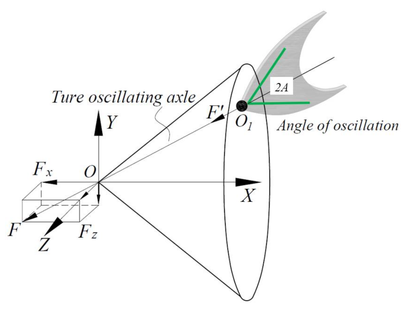
3.1. Conceptual Design of Mechanism

To make the caudal fin oscillate in space, a motion mode with a tapered space was established in the coordinate system O - X Y Z . As shown in Figure 3, the coordinate origin O was the point of the conical shape space, the X -axis was along the axle of the conical shape space, the Y -axis was vertical to the water level, and the Z -axis followed the right hand rule. First of all, for any section that the caudal fin oscillated in, the thrust F produced by the caudal fin’s oscillating would be in line with its oscillating axle O O 1 . Generally speaking, a carangiform fish’s caudal fin would oscillate symmetrically in the horizontal plane- X O Z , but dolphins would flap symmetrically in the vertical plane- X O Y . Both of them can propel in the oscillating axle. Here, if we change the position of the oscillating axle in the conical shape space, the thrust F would evolve into a spatial force composed of three component forces F x , F y and F z . F x would provide a thrust along the X -axis, which would make the robotic fish move forward. F y and F z would be the force sources for diving and turning, respectively. When changing the direction of the oscillating motion, the produced spatial thrust force would satisfy the complicated conditions of robotic fish’s turning and/or diving. As a result, the innovated robotic fish would be able to change its propulsive direction to any direction in space.

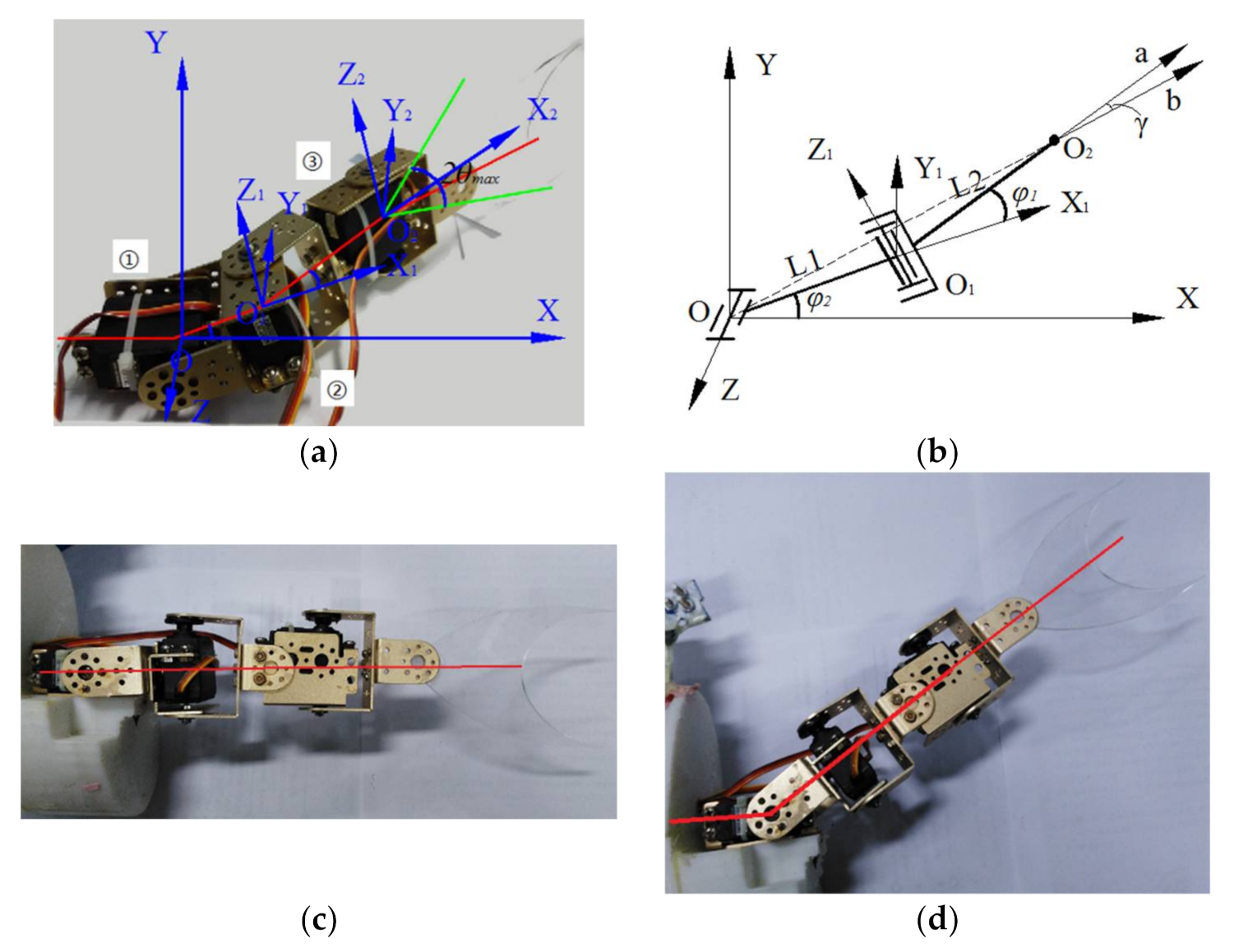
3.2. Conceptual Prototype Design

A real fish-like capability for propulsion and maneuverability could be realized by a good integration of the design and control into this conceptual design. The design with the caudal fin oscillating in space was conducted by changing its orientation in a conical shape space. Specifically, three steering engines are chosen as the main actuators of the whole system with a maximum oscillating range of 180°, as shown in Figure 4a. Here, steering engine ① is used to control the motion of the caudal fin in the O X Y -plane, steering-engine ② is used to control the motion in plane O 1 Y 1 Z 1 , and the coordinate action of the above two steering engines serves to fix the position of O 2 . Then, a new orientation O O 2 , namely the true orientation of the caudal fin, would be formed in space. The oscillating angle is decided by steering engine ③, which is asymmetric around the axis O O 2 .
In this design, we assumed that the motion variables and generalized coordinates of steering engines ①, ② were definite and that the location and the direction of the caudal fin would be directly decided by the position and gesture of point O 2 . The movement postures of the mechanism with steering engines during cruise or diving are shown in Figure 4c,d. Considering that the series of rigid bodies worked with complicated relative motions, a fourth-order matrix equation would be adopted for a convenient calculation. Because the motion variables of every joint were realized by steering engines that would rotate with a single degree-of-freedom, all joints in this mechanism were designed with revolute pairs. The mechanism kinematical graph of the designed mechanism is shown in Figure 4b. In the reference coordinate system O - X Y Z , the coordinate of the oscillating center O 2 was represented as x , y , z T , the direction cosine of the relative vector a of O 2 was represented as l , m , n T , and the direction cosine of the absolute vector b of O 2 was represented as u , v , w T . The matrix equation of the position and gesture of O 2 could be deduced as:
x y z 1 l m n 0 = M 01 M 12 0 0 0 1 1 0 0 0
where M01 and M02 are both direction cosine matrices of the coordinate transformation.
Considering the structural characteristics in Figure 4b, the fourth-order matrix equation would be written as:
M 01 = cos φ 1 0 sin φ 1 L 1 cos φ 1 sin φ 1 0 cos φ 1 L 1 sin φ 1 0 1 0 0 0 0 0 1 , M 12 = cos φ 2 sin φ 2 0 L 2 cos φ 2 sin φ 2 cos φ 2 0 L 2 sin φ 2 0 0 1 0 0 0 0 1
where φ 1 presents the rotational angle of steering engine ①, φ 2 is the rotational angle of steering engine ②, and L 1 presents the distance of the origin O 1 and the origin O .
Substituting these matrices into Equation (1) yields the following equations:
x = L 1 cos φ 1 + L 2 cos φ 1 cos φ 2 y = L 1 sin φ 1 + L 2 sin φ 1 cos φ 2 z = L 2 sin φ 2
l = cos φ 1 cos φ 2 m = sin φ 1 cos φ 2 n = sin φ 2
The distance ρ of the oscillating center O 2 and the origin O could be shown as:
ρ 2 = x 2 + y 2 + z 2 = L 1 2 + L 2 2 + 2 L 1 L 2 cos φ 2
Then, the direction cosine of the absolute vector b could be deduced as:
u , v , w = x ρ , y ρ , z ρ
The motion space of the oscillating center in this design with φ 1 π 6 , π 6 , φ 2 π 6 , π 6 is shown in Figure 5, which shows that the locomotion domain of the oscillating center is nearly half an ellipsoid.
The oscillating plane of steering engine ③ was composed of points O , O 1 and O 2 , and the angle between the relative vector a and absolute vector b in this O O 1 O 2 plane was presented as:
cos γ = a b a b
Here, the oscillating scope of steering engine ③ was π 2 γ A , π 2 γ + A , where A presents the swing amplitude of the caudal fin. Besides, the output signal of steering engine ③ varied as θ = A sin ( 2 π f t ) + π 2 γ .

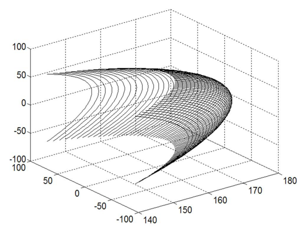
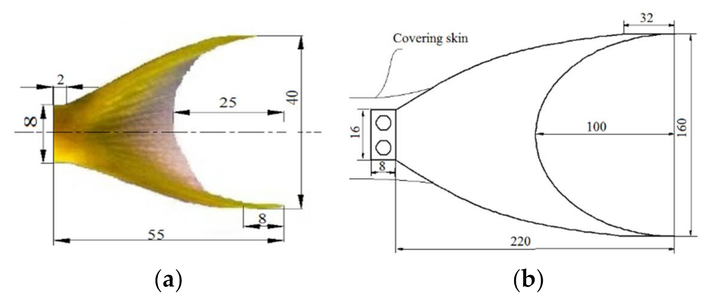
3.3. Design of the Rigid Caudal Fin

Goldfish are a kind of carangiform fish, whose caudal fin stiffness is big enough. Additionally, its biological sample was easy to obtain as our research object, as shown in Figure 6. In order to adapt the size of the steering engine and adjust the optimum measuring range, the size of the caudal fin was approximately four times that of the biological caudal fin. Acrylic material is adopted here to make the bionic fin have a 3-mm thickness. Two holes were punched to connect the stand of steering engine ③ by bolts. Furthermore, the external part was covered with covering skin. The elongation of the caudal fin is 160 mm and the chord length is 220 mm.

4. Experimental Results

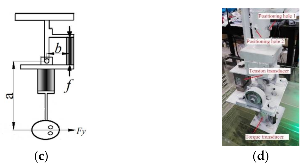
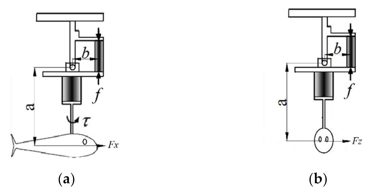
4.1. Experimental Apparatus Design

The experiments were developed to prove the idea that robotic fish could swim nimbly by changing the direction of the caudal fin’s orientation in space. The magnitude and the direction of the force F from the caudal fin oscillating in space would be the main factors for testing the idea. Here, an experimental apparatus was designed to obtain the data acquisition of the spatial force F and torque τ with a torque transducer (HX-917) and tension transducer (LYJ-1) for further analysis, as shown in Figure 7d, and all transducers were working with a sampling speed of 15 times per second. The robotic fish were located at the towing system, and the torque τ around the axis of the torque transducer could be directly measured by HX-917. The thrust F x , lift force F y and lateral force F z were measured separately with the robotic fish swimming along different directions.
When the robotic fish was mounted in an upright direction and with Position hole 1 in operation, the thrust F x could be measured by the tension transducer (LYJ-1) from Positioning hole 1, as shown in Figure 7a. According to Leverage, the actual thrust F x along the axial direction could be described as:
F x = b a y f
where a is the distance between the axles of the fish body and the torque transducer, b is the distance between the axles of the torque transducer and the tension transducer, and f is digital readout of the tension transducer. In our measure mechanism, b a y 1 3 , and as a result the measuring accuracy was improved.

4.2. Experiments

In the experiments, the robotic fish was installed at the end of the torque transducer with the same flow depth. Still water was adopted here to decrease the influence of the resistance of holders and connecting parts. The acquired data was effective when the caudal fin was in stable oscillation. Above all, a snapshot of the apparatus in the experiment is shown in Figure 8. Three comparison experiments on cruise, maneuvering in a plane and maneuvering in space were carried out to test the performance of the spatial oscillating caudal fin. In previous experimental studies, the swing frequency of the caudal fin was set from 0.5 Hz to 1.5 Hz. The propulsive force first increases and then decreases with the increase of the swing frequency, and the propulsive force reaches the peak value near 1 Hz and then decreases. In the meantime, the swimming speed and the efficiency both increase with the increase of the propulsive force and also reach the peak value near 1 Hz. In these three experiments, the oscillating parameters with an amplitude A = 30 ° and f = 1   Hz were adopted to ensure the absolute value of the thrust force constant. When the caudal fin is oscillating in random space, the thrust force F x , the lift F y and the lateral force F z can be deduced by the following equations:
F x = R L cos φ 2 c o s φ 1 F y = R L sin φ 2 F z = R L cos φ 2 s i n φ 1
Here, R L is the lift force of the fluid on the caudal fin according to the theory of the 2D waving plate. Thus, when φ 2 0 , the lift would be generated; when φ 1 0 , the lateral force would be generated. The steering engines’ control parameters varied in these three comparison experiments, as shown in Table 1. In Experiment 1, the robotic fish was controlled to cruise: steering engine ① and steering engine ② both kept 90°, which means φ 1 = 0 and φ 2 = 0 , and steering engine ③ rotated between 60° and 120°; In Experiment 2, the robotic fish was controlled so as to maneuver in a plane and dive in a vertical plane, respectively: steering engine ③ still rotated between 60° and 120° with the angle of steering engine ① fixed at 60° but with steering engine ② still fixed at 90°, which means φ 1 = 30 and φ 2 = 0 ; In Experiment 3, the caudal fin was controlled so as to oscillate in space: steering engine ③ rotated between 75° and 135°, and the angles of steering engine ① and steering engine ② were both kept at 60°, which means φ 1 = 30 and φ 2 = 30 .

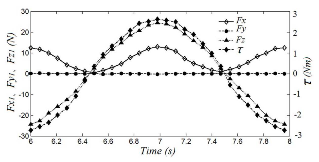
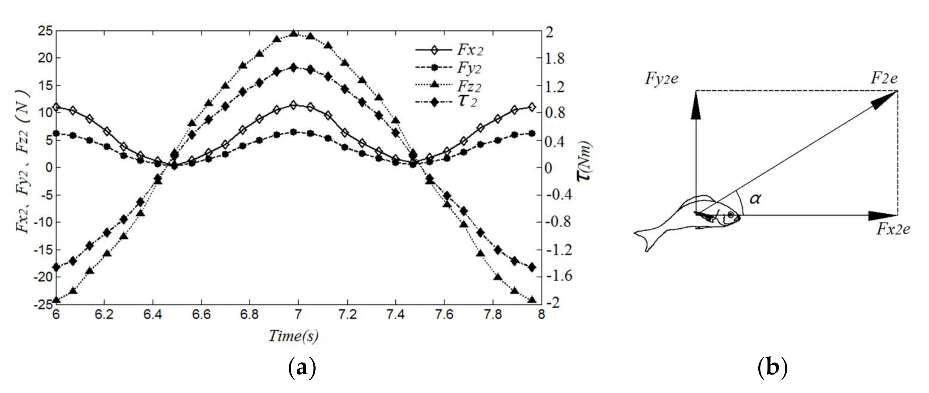
4.3. Results and Discussion

In these three comparison experiments, the forces and torque acting on the caudal fin have been constantly monitored and recorded. The torque on the fixed point, lift force along the coordinate axles, and thrust and lateral force in cruise are shown in Figure 8. In cruise, the forces exerted by the fluid on the caudal fin were composed of two horizontal components, the thrust F x 1 and lateral force F z 1 . From Figure 8, the thrust F x 1 varied periodically and was always larger than zero so as to gain a positive average thrust in a cycle, which means that the robotic fish would gain thrust to advance all the time in a cycle. The lateral force F z 1 also varied periodically, but the average value in a cycle was zero, which would lead to an instantaneous lateral movement without affecting the whole movement state. There is no doubt that the lift force F y 1 had no influence on the caudal fin’s oscillation, that is F y 1 0 . The torque τ 1 varying periodically with a larger amplitude would lead to the swing of the biofish’s forebody.
When the fish dove in the vertical plane, the forces exerted by the fluid on the caudal fin were composed of the vertical component of the lift force F z 2 and two horizontal components: the thrust F x 2 and lateral force F z 2 , as shown in Figure 9a. The trend of the thrust F x 2 and the lateral force F z 2 were similar to the thrust F x 1 , and the average thrust F x 2 e = 5.8   N was approximately 0.88 times as much as the average lateral forces F x 1 e = 6.6   N and the lift force F y 2 with a max value of 6.7 N, which would lead to decreasing the propulsive speed and generating an upward motion trend. The curve of the lateral force F y 2 was quite similar to F z 1 . The trend of the torque τ 2 was also similar to τ 1 , but the value would decrease because the oscillating center was closer to the axle O Y . The average forces in a cycle generated from the caudal fin’s spatial oscillation were illustrated in a rectangle, as shown in Figure 9b. The angle between the average thrust F x 2 e and average lift force F y 2 e was 28.5°, which was close to the turning angle of steering engine ① φ 1 = 30 . Above all, we could conclude that the fish could dive with any angle by changing the orientation of the swing axle in space.
During fish maneuvering in space, the forces exerted by the fluid on the caudal fin were composed of the vertical component of the lift force F z 3 and two horizontal components: the thrust F x 3 and lateral force F y 3 , as shown in Figure 10a. The trend of the thrust F x 3 was still similar to the thrust F x 1 , but the average thrust decreased further with F x 3 e = 5.4   N , which would lead to a propulsive speed along the axle O X . The curve of the lift force F y 3 was almost the same as F y 2 , which meant that the movement along the axle O Y would not be influenced. The curve of the lateral force F z 3 changed to a value greater than F z 1 and F z 2 due to the direction change of the caudal fin’s spatial oscillation. The curve of the lateral force F z 3 varied periodically and asymmetrically with an average lateral force F z 3 e = 1.4   N . Therefore, the fish would move along the axle O Z . Of course, the specific route would be further investigated in future research. The average forces generated from the caudal fin’s spatial oscillation were illustrated in a cuboid, as shown in Figure 10b. The resultant force F 3 e was equal to 6.5 N, which was much closer to the thrust F x 1 = F x 1 e = 6.6   N . The angle between the unit vector of the resultant force F x 2 and the direction cosines of the absolute vector F y 2 was 6°. Above all, we could conclude that the biofish could maneuver in space by changing the orientation of the swing axle.
The above three experiment results, the gesture direction of the fish body and the propulsive direction have been strictly distinguished instead of overlapping, which is different from traditional concepts. The propulsive routes of the robotic fish were determined by the value and the orientation angle of the spatial force F 3 e , as shown in Figure 11.

5. Results

In this paper, a robotic fish with a spatial oscillating rigid caudal fin has been developed to improve propulsion and maneuverability in space.
The designed robotic fish was composed of three steering engines and a rigid caudal fin. In particular, steering engine ① and steering engine ② were combined to adjust the oscillating orientation of the caudal fin according to the actual oscillating direction, and the oscillating scope of steering engine ③ would make the appropriate adjustment. Then, the oscillation of the robotic fish could be realized by combining steering engine ③ and the rigid caudal fin.
An experimental apparatus was developed to measure and record a series of produced thrusts, lift forces, lateral forces and torques. Then, three experiments on cruise, diving and maneuvering with the caudal fin’s oscillation in random space were conducted comprehensively. The experimental results indicated that maneuvering in any direction could be realized by changing the orientation of the caudal fin.

Author Contributions

Conceptualization, S.W.; Validation, S.W. and Y.H.; Formal analysis, S.W.; investigation, Y.H.; Writing—original draft preparation, Y.H. and S.M.; Writing—review and editing, S.W. and S.M.; Project administration, S.W.; Funding acquisition, S.W. All authors have read and agreed to the published version of the manuscript.

Funding

This research is financially supported by National Nature Science Foundation of China (No. 51975115).

Institutional Review Board Statement

Not applicable.

Informed Consent Statement

Not applicable.

Data Availability Statement

The data presented in this paper are available on request from the corresponding author.

Acknowledgments

In this section, you can acknowledge any support given which is not covered by the author contribution or funding sections. This may include administrative and technical support, or donations in kind (e.g., materials used for experiments).

Conflicts of Interest

The authors declare no conflict of interest. The funders had no role in the design of the study; in the collection, analyses, or interpretation of data; in the writing of the manuscript, or in the decision to publish the results.

References

  1. Cai, Y.; Bi, S.; Li, G.; Hildre, H.P.; Zhang, H. From Natural Complexity to Biomimetic Simplification: The Realization of Bionic Fish Inspired by the Cownose Ray. IEEE Robot. Autom. Mag. 2019, 26, 27–38. [Google Scholar] [CrossRef]
  2. Zhang, C. Simulation Analysis of Bionic Robot Fish Based on MFC Materials. Math. Probl. Eng. 2019, 66, 1226–1234. [Google Scholar] [CrossRef] [Green Version]
  3. Heathcote, S.; Wang, Z. Effect of spanwise flexibility on flapping wing propulsion. Fluids Struct. 2008, 24, 183–199. [Google Scholar] [CrossRef]
  4. Borazjani, I.; Sotiropoulos, F. Numerical investigation of the hydrodynamics of carangiform swimming in the transitional and inertial flow regimes. Exp. Biol. 2008, 211, 1541–1558. [Google Scholar] [CrossRef] [PubMed] [Green Version]
  5. Yu, J.Z.; Hu, Y.H. Dolphin-like propulsive mechanism based on an adjustable Scotch yoke. Mech. Mach. Theory 2009, 44, 603–614. [Google Scholar] [CrossRef]
  6. Apalkov, A.; Fernandez, R. Mechanical actuator for biomimetic propulsion and the effect of the caudal fin elasticity on the swimming performance. Sens. Actuators A 2012, 178, 164–174. [Google Scholar] [CrossRef] [Green Version]
  7. Nguyen, P.L. Dynamic Modeling and Experiment of a Fish Robot with a Flexible Tail Fin. Bionic Eng. 2013, 10, 39–45. [Google Scholar] [CrossRef]
  8. Mason, R.; Joel, W.B. Experiments in carangiform robotic fish locomotion. Robotics and Automation Proceedings. In Proceedings of the IEEE International Conference, San Francisco, CA, USA, 24–28 April 2000; pp. 428–435. [Google Scholar]
  9. Liang, C.Q. Research on Fish-Liked Propulsion Technology and SPC-Ⅱ Propulsion System Design; Harbin Engineering University: Harbin, China, 2004. [Google Scholar]
  10. Conte, J.; Hover, F.S. A fast-starting mechanical fish that accelerates at 40 m s−2. Bioinspir. Biomim. 2010, 5, 1–9. [Google Scholar] [CrossRef] [Green Version]
  11. Morgansen, K.A.; Triplett, B.I.; Klein, D.J. Geometric Methods for Modeling and Control of Free-Swimming Fin-Actuated Underwater Vehicles. IEEE Trans. Robot. 2007, 23, 1184–1199. [Google Scholar] [CrossRef]
  12. Castaño, M.L.; Tan, X.B. Model Predictive Control-Based Path-Following for Tail-Actuated Robotic Fish. Dyn. Syst. Meas. Control 2019, 1, 141. [Google Scholar] [CrossRef] [Green Version]
  13. Yu, J.Z.; Tan, M. Development of a biomimetic robotic fish and its control algorithm. IEEE Trans. Cybern. 2004, 34, 1798–1810. [Google Scholar] [CrossRef]
  14. Yu, J.Z.; Wen, L. A survey on fabrication, control, and hydrodynamic function of biomimetic robotic fish. Sci. China Technol. Sci. 2017, 60, 1365–1380. [Google Scholar] [CrossRef]
  15. Yu, J.Z.; Wang, M. Motion Control and Motion Coordination of Bionic Robotic Fish: A Review. Bionic Eng. 2018, 15, 579–598. [Google Scholar] [CrossRef]
  16. Zhao, S.Q. Experimental Research of A Tail-Fin Propulsive System; Harbin Engineering University: Harbin, China, 2008. [Google Scholar]
  17. Nguyen, Q.S.; Heo, S. Performance evaluation of an improved fish robot actuated by piezoceramic actuators. Smart Mater. Struct. 2010, 19, 1–8. [Google Scholar] [CrossRef]
  18. George, V.; Lauder, E.J.; Anderson, J.T. Fish biorobotics: Kinematics and hydrodynamics of self-propulsion. Exp. Biol. 2007, 210, 2767–2780. [Google Scholar]
  19. Salumäe, T.; Kruusmaa, M. A Flexible Fin with Bio-Inspired Stiffness Profile and Geometry. Bionic Eng. 2011, 8, 418–428. [Google Scholar] [CrossRef]
  20. Hadi, E.D.; Taavi, S. Modelling of a biologically inspired robotic fish driven by compliant parts. Bioinspir. Biomim. 2014, 9, 1–11. [Google Scholar]
  21. Barrett, D.S.; Triantafyllou, M.S.; Yue, D.P. Drag reduction in fish-like locomotion. Fluid Mech. 1999, 392, 183–212. [Google Scholar] [CrossRef] [Green Version]
  22. Mwaffo, V. Zebrafish swimming in the flow: A particle image velocimetry study. PEER J. 2017, 5, 4041. [Google Scholar] [CrossRef] [Green Version]
  23. Chan, W.L.; Kang, T.; Lee, Y.J. Experiments and identification of an ostraciiform fish robot. In Proceedings of the 2007 IEEE International Conference on Robotics and Biomimetics (ROBIO), Sanya, China, 15–18 December 2008. [Google Scholar]
  24. Costa, D.; Franciolini, M.; Palmieri, G.; Crivellini, A.; Scaradozzi, D. Computational fluid dynamics analysis and design of an ostraciiform swimming robot. In Proceedings of the IEEE International Conference on Robotics and Biomimetics (ROBIO), Macau, China, 5–8 December 2017; pp. 135–140. [Google Scholar]
  25. Costa, D.; Callegari, M.; Palmieri, G.; Scaradozzi, D.; Brocchini, M.; Zitti, G. Experimental Setup for the Validation of the Bio-Inspired Thruster of an Ostraciiform Swimming Robot. In Proceedings of the 2018 14th IEEE/ASME International Conference on Mechatronic and Embedded Systems and Applications (MESA), Oulu, Finland, 2–4 July 2018; pp. 1–6. [Google Scholar]
  26. Wen, L.; Wang, T.M. Hydrodynamic investigation of a self-propelled robotic fish based on a force-feedback control method. Bioinspir. Biomim. 2012, 7, 1–17. [Google Scholar] [CrossRef] [Green Version]
  27. Beal, D.N.; Bandyopadhyay, P.R. A harmonic model ofhydrodynamic forces produced by a flapping fin. Exp. Fluids 2007, 6, 75–82. [Google Scholar]
  28. Wang, S.Y.; Zhu, J.; Wang, X.G.; Li, Q.F.; Zhu, H.Y.; Zhou, R. Optimization and simulation of a bionic fish tail driving system based on linear hypocycloid with hydrodynamics. Adv. Mech. Eng. 2017, 9, 1–10. [Google Scholar] [CrossRef] [Green Version]
  29. Wang, S.Y.; Wang, X.G.; Li, Q. A Bionic Fish Propulsive Mechanism with Caudal Fin Oscillating in Variable Direction Based on Linear Hypocycloid. In Proceedings of the 14th IFToMM World Congress, Taipei, Taiwan, 25–30 October 2015; pp. 28–32. [Google Scholar]
  30. Ren, Q.Y.; Xu, J.X. A GIM-based biomimetic learning approach for motion generation of a multi-joint robotic fish. Bionic Eng. 2013, 10, 423–433. [Google Scholar] [CrossRef]
  31. Li, Z.C. The Software and Hard Hardware Design and Dynamic Research on the Robot Fish; Harbin Institute of Technology: Harbin, China, 2009. [Google Scholar]
Figure 1. The relation between the oscillating axle and the fish body.
Jmse 09 00435 g001
Figure 2. The swimming route of the robotic fish from point A to point B.
Jmse 09 00435 g002
Figure 3. Motion model of the caudal fin with a tapered motion space.
Jmse 09 00435 g003
Figure 4. Structure design of robotic fish. (a) Adjustment part of the oscillating center composed of steering engines. (b) Schematic of the adjustment system. (c) The location of the steering engines during cruise. (d) The location of the steering engines during diving.
Jmse 09 00435 g004
Figure 5. The oscillating center’s locomotion domain.
Jmse 09 00435 g005
Figure 6. Rigid caudal fin’s model from a goldfish’s tail. (a) Structural size of the goldfish’s tail; (b) Schematic diagram of the bionic caudal fin.
Jmse 09 00435 g006
Figure 7. The schematics of the designed measure system. (a) The measured schematic of the thrust F x ; (b) The measured schematic of the lateral force F z ; (c) The measured schematic of the lift force F y ; (d) The designed measurement apparatus.
Jmse 09 00435 g007aJmse 09 00435 g007b
Figure 8. F y 1 , F z 1 and τ 2 in cruise.
Jmse 09 00435 g008
Figure 9. Hydrodynamic performance of the caudal fin’s spatial oscillation during diving. (a) Comparison of F x 2 , F y 2 and τ 2 in diving. (b) Diagrams of the force during diving.
Jmse 09 00435 g009
Figure 10. Hydrodynamic performance of the caudal fin’s spatial oscillation in random space. (a) Comparison of F x 3 , F y 3 , F z 3 and τ 2 in random space. (b) Diagrams of the force in random space.
Jmse 09 00435 g010
Figure 11. The estimated swimming route under the action of the spatial force.
Jmse 09 00435 g011
Table 1. The steering engines’ control parameters in the comparison experiments.
VariableExperiment 1Experiment 2Experiment 3
φ 1 −30°−30°
φ 2 0−30°
φ 3 [60°,120°][60°,120°][75°,135°]
Publisher’s Note: MDPI stays neutral with regard to jurisdictional claims in published maps and institutional affiliations.

