
Ocean Thermal Energy Conversion and Other Uses of Deep Sea Water: A Review


Abstract
1. Introduction
2. Temperature in the Sea and Otec Cycles
- The surface: From 100 to 200 m deep, which acts as a heat collector, with temperatures range between 25 and 30 C.
- The intermediate: Between 200 and 400 m deep, with a fast temperature variation and acting as a thermal barrier between the upper and lower layers.
- The deep: The temperature decreases smoothly, reaching 4 C at 1000 m and 2 C at 5000 m.
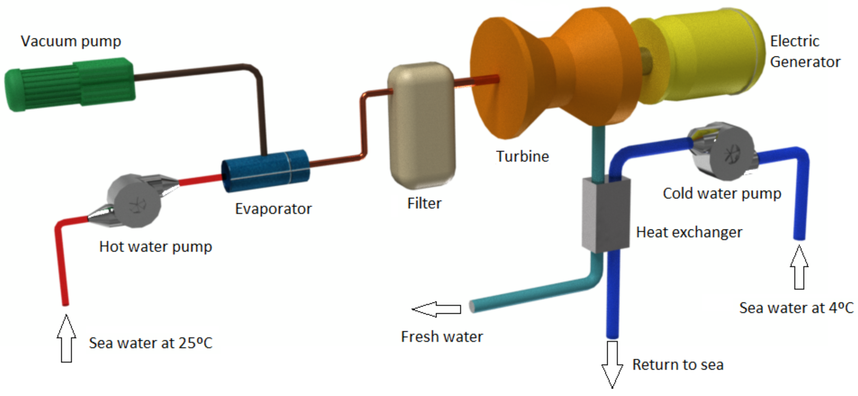
2.1. Open-Cycle
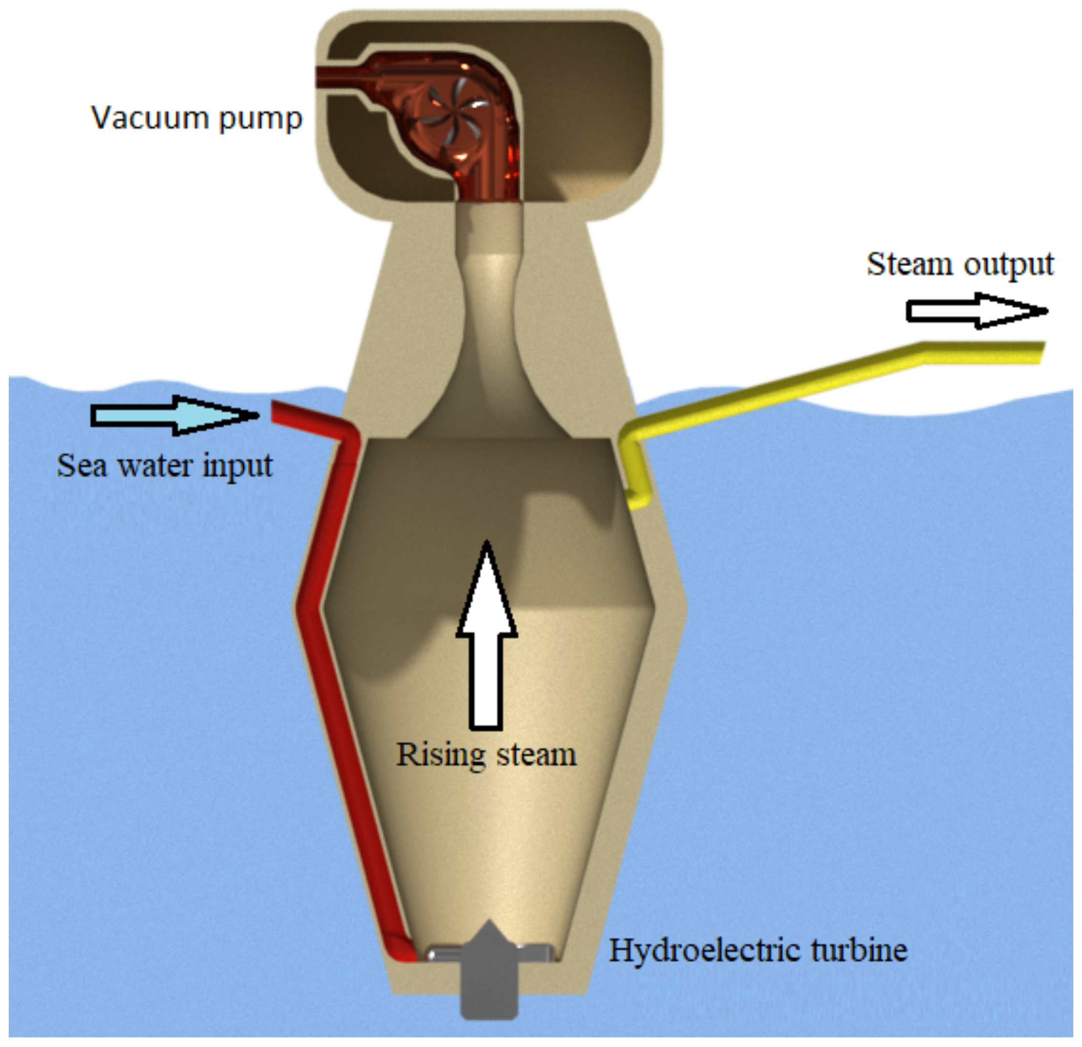
2.2. Open-Cycle with Mist Lift System
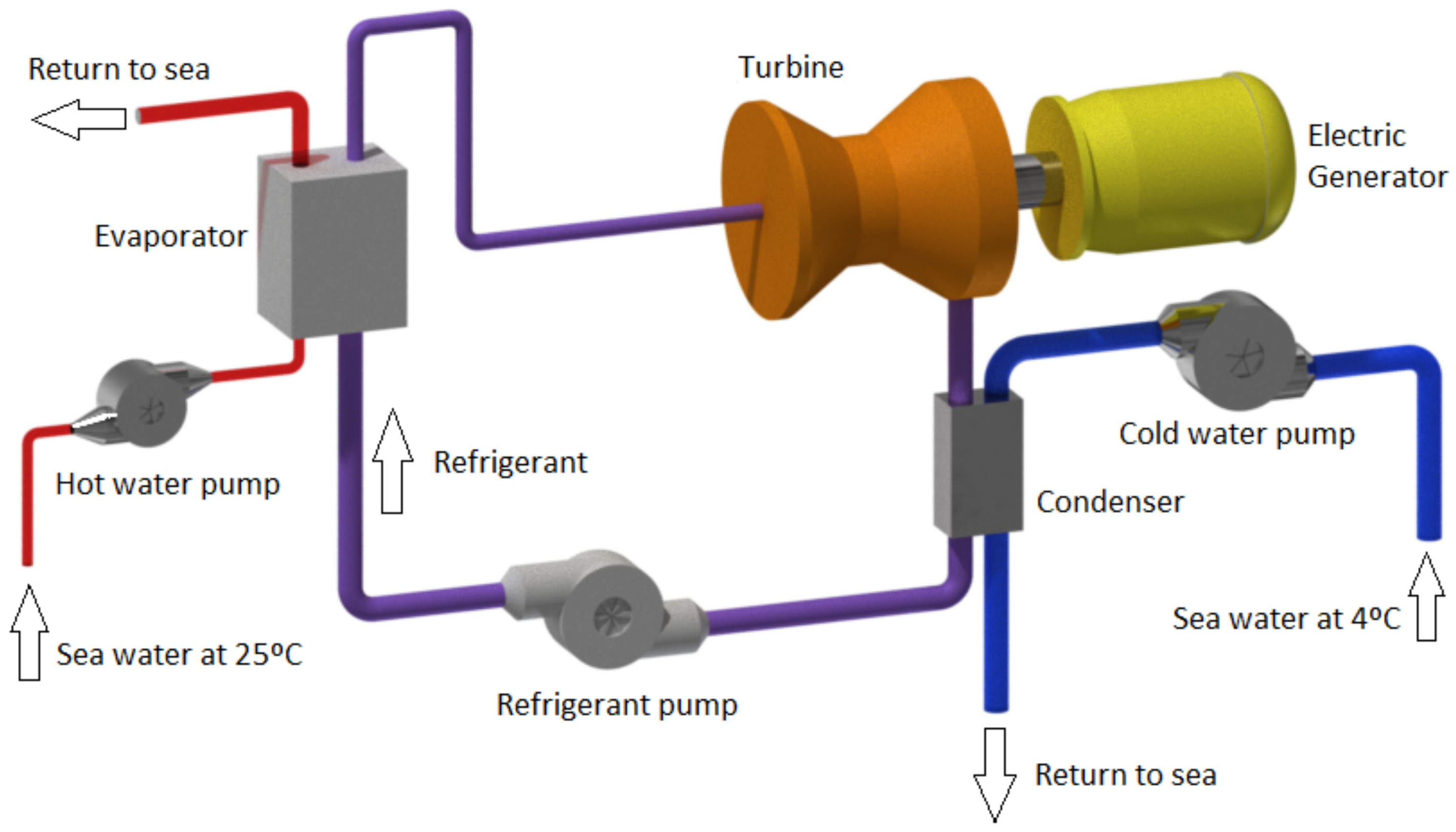
2.3. Closed-Cycle
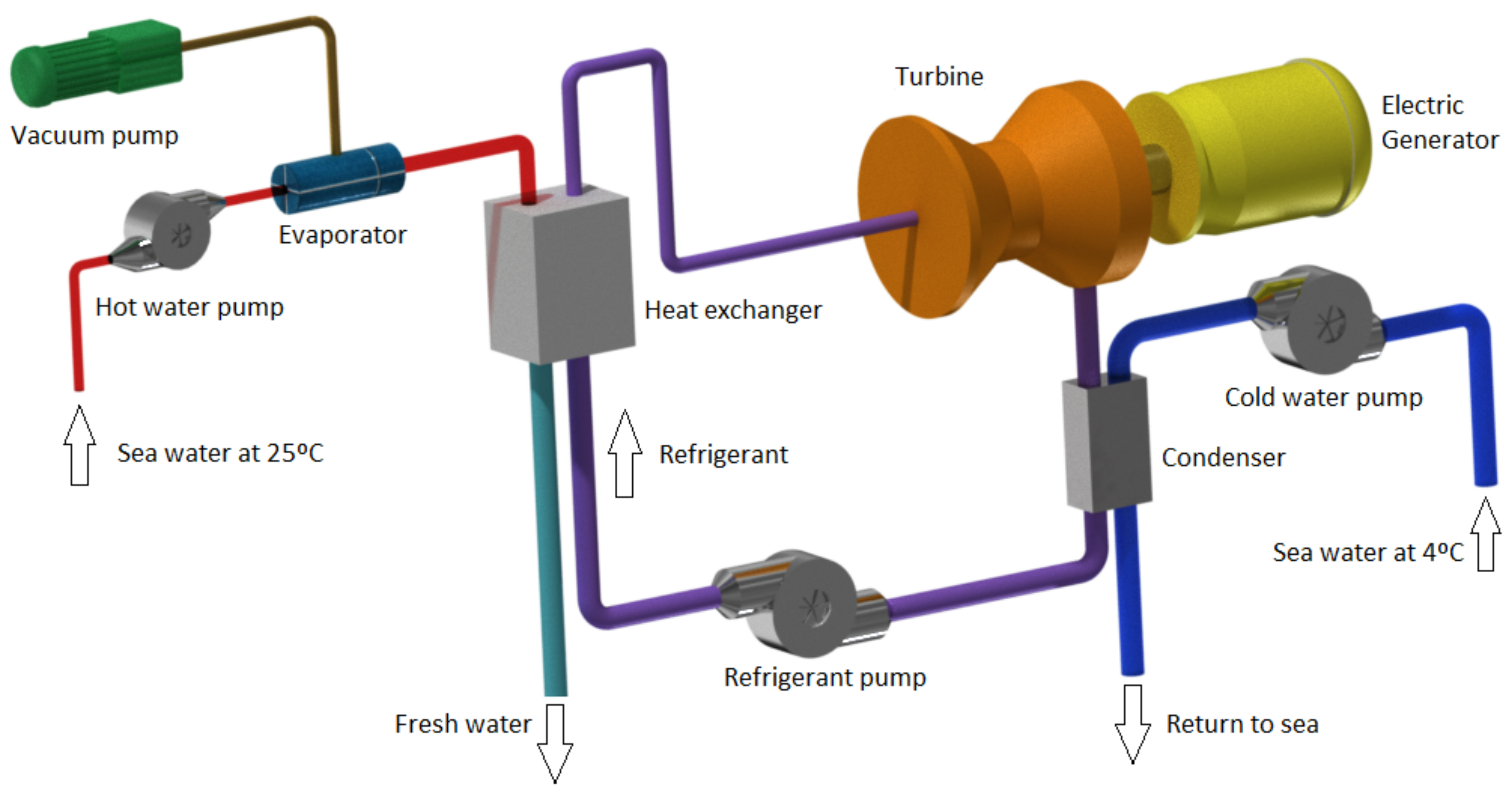
2.4. Hybrid Cycle
2.5. Optimizations for OTEC
2.5.1. Thermodynamic Optimizations for OTEC
2.5.2. Designs for OTEC System Components
3. Location of an Otec Power Plant
3.1. OTEC Onshore
3.2. OTEC Offshore
3.3. Floating OTEC
4. Other Uses of Deep Ocean Water
4.1. Desalinated Water
4.2. Refrigerated Soil Agriculture
4.3. Aquaculture
5. History and Otec Projects around the World
5.1. Beginnings of OTEC Technology
5.2. OTEC in Japan
5.3. OTEC in United States
5.4. NEMO Project
5.5. Other OTEC Projects in Development
6. Environmental Impact
7. Technical Challenges and Restrictions
8. Economic Viability
9. Conclusions
Author Contributions
Funding
Institutional Review Board Statement
Informed Consent Statement
Conflicts of Interest
Abbreviations
| OTEC | Ocean Thermal Energy Conversion |
| GHG | Global emissions of greenhouse gases |
| DCNS | Direction des Constructions Navales |
| NEMO | New Energy for Martinique and Overseas |
References
- Bank, W. World Development Indicators; World Bank: Washington, DC, USA, 2019. [Google Scholar]
- Meckling, J. The developmental state in global regulation: Economic change and climate policy. Eur. J. Int. Relations 2018, 24, 58–81. [Google Scholar] [CrossRef]
- Seungtaek, L.; Hosaeng, L.; Junghyun, M.; Hyeonju, K. Simulation Data of Regional Economic Analysis of OTEC for Applicable Area. Processes 2020, 8, 1107. [Google Scholar] [CrossRef]
- Ullah, N.; Ali, M.A.; Ibeas, A.; Herrera, J. Adaptive fractional order terminal sliding mode control of a doubly fed induction generator-based wind energy system. IEEE Access 2017, 5, 21368–21381. [Google Scholar] [CrossRef]
- Tobón, A.; Peláez-Restrepo, J.; Villegas-Ceballos, J.P.; Serna-Garcés, S.I.; Herrera, J.; Ibeas, A. Maximum power point tracking of photovoltaic panels by using improved pattern search methods. Energies 2017, 10, 1316. [Google Scholar] [CrossRef]
- Gohar Ali, H.; Vilanova Arbos, R.; Herrera, J.; Tobón, A.; Peláez-Restrepo, J. Non-linear sliding mode controller for photovoltaic panels with maximum power point tracking. Processes 2020, 8, 108. [Google Scholar] [CrossRef]
- Tobón, A.; Peláez-Restrepo, J.; Montano, J.; Durango, M.; Herrera, J.; Ibeas, A. MPPT of a photovoltaic panels array with partial shading using the IPSM with implementation both in simulation as in hardware. Energies 2020, 13, 815. [Google Scholar] [CrossRef]
- Thirugnana, S.T.; Jaafar, A.B.; Yasunaga, T.; Nakaoka, T.; Ikegami, Y.; Su, S. Estimation of Ocean Thermal Energy Conversion Resources in the East of Malaysia. J. Mar. Sci. Eng. 2021, 9, 22. [Google Scholar] [CrossRef]
- Bernardoni, C.; Binotti, M.; Giostri, A. Techno-economic analysis of closed OTEC cycles for power generation. Renew. Energy 2019, 132, 1018–1033. [Google Scholar] [CrossRef]
- Drew, B.; Plummer, A.R.; Sahinkaya, M.N. A review of wave energy converter technology. Proc. Inst. Mech. Eng. Part J. Power Energy 2009, 223, 887–902. [Google Scholar] [CrossRef]
- Alawadhi, K.; Alhouli, Y.; Ashour, A.; Alfalah, A. Design and Optimization of a Radial Turbine to Be Used in a Rankine Cycle Operating with an OTEC System. J. Mar. Sci. Eng. 2020, 8, 855. [Google Scholar] [CrossRef]
- Ishaq, H.; Dincer, I. A comparative evaluation of OTEC, solar and wind energy based systems for clean hydrogen production. J. Clean. Prod. 2020, 246, 118736. [Google Scholar] [CrossRef]
- Chen, W.B.; Liu, W.C.; Hsu, M.H. Modeling evaluation of tidal stream energy and the impacts of energy extraction on hydrodynamics in the Taiwan Strait. Energies 2013, 6, 2191–2203. [Google Scholar] [CrossRef]
- Xu, Q.K.; Liu, H.W.; Lin, Y.G.; Yin, X.X.; Li, W.; Gu, Y.J. Development and experiment of a 60 kW horizontal-axis marine current power system. Energy 2015, 88, 149–156. [Google Scholar] [CrossRef]
- Seungtaek, L.; Hoseang, L.; Hyeonju, K. Dynamic Simulation of System Performance Change by PID Automatic Control of Ocean Thermal Energy Conversion. J. Mar. Sci. Eng. 2020, 8, 59. [Google Scholar] [CrossRef]
- Davila-Vilchis, J.; Mishra, R. Performance of a hydrokinetic energy system using an axial-flux permanent magnet generator. Energy 2014, 65, 631–638. [Google Scholar] [CrossRef]
- Rourke, F.O.; Boyle, F.; Reynolds, A. Marine current energy devices: Current status and possible future applications in Ireland. Renew. Sustain. Energy Rev. 2010, 14, 1026–1036. [Google Scholar] [CrossRef]
- Li, Y.; Calışal, S.M. Modeling of twin-turbine systems with vertical axis tidal current turbines: Part I—Power output. Ocean Eng. 2010, 37, 627–637. [Google Scholar] [CrossRef]
- Jia, Y.; Nihous, G.C.; Rajagopalan, K. An Evaluation of the Large-Scale Implementation of Ocean Thermal Energy Conversion (OTEC) Using an Ocean General Circulation Model with Low-Complexity Atmospheric Feedback Effects. J. Mar. Sci. Eng. 2018, 6, 12. [Google Scholar] [CrossRef]
- Zhao, B.; Wang, S.; Liu, H.; Xu, J.; Fu, K.; Klimont, Z.; Hao, J.; He, K.; Cofala, J.; Amann, M. NO x emissions in China: Historical trends and future perspectives. Atmos. Chem. Phys. 2013, 13, 9869–9897. [Google Scholar] [CrossRef]
- Nihous, G. A preliminary investigation of the effect of ocean thermal energy conversion (OTEC) effluent discharge options on Global OTEC Resources. J. Mar. Sci. Eng. 2018, 6, 25. [Google Scholar] [CrossRef]
- Wang, M.; Jing, R.; Zhang, H.; Meng, C.; Li, N.; Zhao, Y. An innovative Organic Rankine Cycle (ORC) based Ocean Thermal Energy Conversion (OTEC) system with performance simulation and multi-objective optimization. Appl. Therm. Eng. 2018, 145, 743–754. [Google Scholar] [CrossRef]
- Rau, G.H.; Baird, J.R. Negative-CO2-emissions ocean thermal energy conversion. Renew. Sustain. Energy Rev. 2018, 95, 265–272. [Google Scholar] [CrossRef]
- Yang, M.H.; Yeh, R.H. Analysis of optimization in an OTEC plant using organic Rankine cycle. Renew. Energy 2014, 68, 25–34. [Google Scholar] [CrossRef]
- Eldred, M.; Landherr, A.; Chen, I.C. Comparison of Aluminum Alloys and Manufacturing Processes Based on Corrosion Performance for Use in OTEC Heat Exchangers. In Proceedings of the Offshore Technology Conference, Houston, TX, USA, 3–6 May 2010. [Google Scholar]
- Boehlert, G.W.; Gill, A.B. Environmental and ecological effects of ocean renewable energy development: A current synthesis. Oceanography 2010, 23, 68–81. [Google Scholar] [CrossRef]
- Heydt, G.T. An assessment of ocean thermal energy conversion as an advanced electric generation methodology. Proc. IEEE 1993, 81, 409–418. [Google Scholar] [CrossRef]
- Comfort, C.M.; Vega, L. Environmental assessment for ocean thermal energy conversion in Hawaii: Available data and a protocol for baseline monitoring. In Proceedings of the OCEANS’11 MTS/IEEE KONA, Waikoloa, HI, USA, 19–22 September 2011; pp. 1–8. [Google Scholar]
- Lee, C.; Ridgway, S. Vapor/droplet coupling and the mist flow (OTEC) cycle. J. Sol. Energy Eng. 1983, 105, 111–118. [Google Scholar] [CrossRef]
- Cavrot, D. Economics of ocean thermal energy conversion (OTEC). Renew. Energy 1993, 3, 891–896. [Google Scholar] [CrossRef]
- Cunningham, J.; Magdol, Z.; Kinner, N. Ocean Thermal Energy Conversion: Assessing Potential Physical, Chemical, and Biological Impacts and Risks. Report by University of New Hampshire. Report for National Oceanic and Atmospheric Administration (NOAA). New Hamphsire, Durham, NH. 2010. Available online: https://tethys.pnnl.gov/publications/ocean-thermal-energy-conversion-assessing-potential-physical-chemical-biological (accessed on 24 March 2021).
- Cable, B.; Tayler, W.; Tindal, C.; Varley, R.; Brissey, L. The Navy’s Ocean Thermal Energy Conversion program. In Proceedings of the OCEANS 2010 MTS/IEEE SEATTLE, Seattle, WA, USA, 20–23 September 2010; pp. 1–8. [Google Scholar]
- Von Jouanne, A.; Brekken, T.K. Ocean and geothermal renewable energy systems. In Power Electronics in Renewable Energy Systems and Smart Grid: Technology and Applications; Wiley: Hoboken, NJ, USA, 2019; pp. 391–441. [Google Scholar]
- Hendrawan, A.; Cilacap, A.M.N. Calculation of power pumps on otec power plant ocean (ocean thermal energy conversion). ICoSASTE 2019, 201, 14–15. [Google Scholar]
- Vyawahare, M. Hawaii first to harness deep-ocean temperatures for power. Sci. Am. 2015, 27. Available online: https://www.scientificamerican.com/article/hawaii-first-to-harness-deep-ocean-temperatures-for-power/ (accessed on 24 March 2021).
- Daniel, T. A Brief History of OTEC Research at Nelha; Natural Energy Laboratory of Hawaii Authority: Kailua-Kona, HI, USA, 1999. [Google Scholar]
- Ng, K.C.; Shahzad, M.W. Sustainable desalination using ocean thermocline energy. Renew. Sustain. Energy Rev. 2018, 82, 240–246. [Google Scholar] [CrossRef]
- Liao, X.; Hall, J.W. Drivers of water use in China’s electric power sector from 2000 to 2015. Environ. Res. Lett. 2018, 13, 094010. [Google Scholar] [CrossRef]
- Mckenna, P. Deep oceans may offer “limitless” green energy. New Sci. 2008, 200, 28–29. [Google Scholar] [CrossRef]
- Stene, J. Design and application of ammonia heat pump systems for heating and cooling of non-residential buildings. In Proceedings of the 8th IIR Gustav Lorentzen Conference on Natural Working Fluids, Copenhagen, Denmark, 7–10 September 2008. [Google Scholar]
- Yasunaga, T.; Ikegami, Y.; Monde, M. Performance Test of OTEC with Ammonia/water as Working Fluid Using Shell and Plate Type Heat Exchangers, Effects of Heat Source Temperature and Flow Rate. Trans. JAME B 2008, 74, 445–452. [Google Scholar]
- Oahu, H. Aquaculture updates in the Northern Pacific: Hawaii, Federated States of Micronesia, Palau, and Saipan. In SPC Fisheries Newsletter No. 118; Produced by the Information Section; Marine Resources Division, SPC: Noumea Cedex, New Caledonia, 2006. [Google Scholar]
- Claude, G. Power from the tropical seas. Mech. Eng. 1930, 52, 1039–1044. [Google Scholar]
- Nihous, G.; Vega, L. A review of some semi-empirical OTEC effluent discharge models. In Proceedings of the OCEANS 91: Ocean Technologies and Opportunities in the Pacific for the 90’s, Honolulu, HI, USA, 1–3 October 1991. [Google Scholar]
- Syed, M.; Nihous, G.; Vega, L. Use of cold seawater for air conditioning. In Proceedings of the OCEANS 91: Ocean Technologies and Opportunities in the Pacific for the 90’s, Honolulu, HI, USA, 1–3 October 1991. [Google Scholar]
- Yasunaga, T.; Ikegami, Y. Application of finite-time thermodynamics for evaluation method of heat engines. Energy Procedia 2017, 129, 995–1001. [Google Scholar] [CrossRef]
- Yasunaga, T.; Fontaine, K.; Morisaki, T.; Ikegami, Y. Performance Evaluation of Heat Exchangers for Application to Ocean Thermal Energy Conversion System; Journal of OTEC (Departmental Bulletin Paper); Institute of Ocean Energy Saga University Japan: Saga, Japan, 2017; Volume 22, pp. 65–75. [Google Scholar]
- Yasunaga, T.; Koyama, N.; Noguchi, T.; Morisaki, T.; Ikegami, Y. Thermodynamical optimum heat source mean velocity in heat exchangers on OTEC. In Proceedings of the Grand Renewable Energy, Yokohama, Japan, 17–22 June 2018. [Google Scholar]
- Fontaine, K.; Yasunaga, T.; Ikegami, Y. OTEC maximum net power output using Carnot cycle and application to simplify heat exchanger selection. Entropy 2019, 21, 1143. [Google Scholar] [CrossRef]
- Yasunaga, T.; Ikegami, Y. Finite-time thermodynamic model for evaluating heat engines in ocean thermal energy conversion. Entropy 2020, 22, 211. [Google Scholar] [CrossRef]
- Morisaki, T.; Ikegami, Y. Maximum power of a multistage Rankine cycle in low-grade thermal energy conversion. Appl. Therm. Eng. 2014, 69, 78–85. [Google Scholar] [CrossRef]
- Yasunaga, T.; Noguchi, T.; Morisaki, T.; Ikegami, Y. Basic heat exchanger performance evaluation method on OTEC. J. Mar. Sci. Eng. 2018, 6, 32. [Google Scholar] [CrossRef]
- Ikegami, Y.; Yasunaga, T.; Morisaki, T. Ocean Thermal Energy Conversion Using Double-Stage Rankine Cycle. J. Mar. Sci. Eng. 2018, 6, 21. [Google Scholar] [CrossRef]
- Matsuda, Y.; Yoshitake, T.; Sugi, T.; Goto, S.; Morisaki, T.; Yasunaga, T.; Ikegami, Y. Construction of a Static Model for Power Generation of OTEC Plant Using Uehara Cycle Based on Experimental Data. J. Mar. Sci. Eng. 2018, 6, 18. [Google Scholar] [CrossRef]
- Feng, H.; Chen, W.; Chen, L.; Tang, W. Power and efficiency optimizations of an irreversible regenerative organic Rankine cycle. Energy Convers. Manag. 2020, 220, 113079. [Google Scholar] [CrossRef]
- Feng, H.; Qin, W.; Chen, L.; Cai, C.; Ge, Y.; Xia, S. Power output, thermal efficiency and exergy-based ecological performance optimizations of an irreversible KCS-34 coupled to variable temperature heat reservoirs. Energy Convers. Manag. 2020, 205, 112424. [Google Scholar] [CrossRef]
- Feng, H.; Chen, L.; Wu, Z.; Xie, Z. Constructal design of a shell-and-tube heat exchanger for organic fluid evaporation process. Int. J. Heat Mass Transf. 2019, 131, 750–756. [Google Scholar] [CrossRef]
- Feng, H.; Chen, L.; Wu, Z.; Xie, Z.; Xia, S. Constructal optimization for an organic fluid shell-and-tube heat exchanger based on entransy theory. Sci. Sin. Technol. 2020, 50, 1577–1587. [Google Scholar] [CrossRef]
- Cai, C.; Feng, H.; Chen, L.; Wu, Z.; Xie, Z. Constructal design of a shell-and-tube evaporator with ammonia-water working fluid. Int. J. Heat Mass Transf. 2019, 135, 541–547. [Google Scholar] [CrossRef]
- Wu, Z.; Feng, H.; Chen, L.; Xie, Z.; Cai, C. Pumping power minimization of an evaporator in ocean thermal energy conversion system based on constructal theory. Energy 2019, 181, 974–984. [Google Scholar] [CrossRef]
- Feng, H.; Cai, C.; Chen, L.; Wu, Z.; Lorenzini, G. Constructal design of a shell-and-tube condenser with ammonia-water working fluid. Int. Commun. Heat Mass Transf. 2020, 118, 104867. [Google Scholar] [CrossRef]
- Wu, Z.; Feng, H.; Chen, L.; Ge, Y. Performance Optimization of a Condenser in Ocean Thermal Energy Conversion (OTEC) System Based on Constructal Theory and a Multi-Objective Genetic Algorithm. Entropy 2020, 22, 641. [Google Scholar] [CrossRef]
- Wu, Z.; Feng, H.; Chen, L.; Xie, Z.; Cai, C.; Xia, S. Optimal design of dual-pressure turbine in OTEC system based on constructal theory. Energy Convers. Manag. 2019, 201, 112179. [Google Scholar] [CrossRef]
- Wu, Z.; Feng, H.; Chen, L.; Tang, W.; Shi, J.; Ge, Y. Constructal thermodynamic optimization for ocean thermal energy conversion system with dual-pressure organic Rankine cycle. Energy Convers. Manag. 2020, 210, 112727. [Google Scholar] [CrossRef]
- You, J.; Feng, H.; Chen, L.; Xie, Z.; Xia, S. Constructal design and experimental validation of a non-uniform heat generating body with rectangular cross-section and parallel circular cooling channels. Int. J. Heat Mass Transf. 2020, 148, 119028. [Google Scholar] [CrossRef]
- Troina, G.; Cunha, M.; Pinto, V.; Rocha, L.; Santos, E.D.; Fragassa, C.; Isoldi, L. Computational Modeling and Constructal Design Theory Applied to the Geometric Optimization of Thin Steel Plates with Stiffeners Subjected to Uniform Transverse Load. Metals 2020, 10, 220. [Google Scholar] [CrossRef]
- Hazarika, S.A.; Bhanja, D.; Nath, S. Fork-shaped constructal fin array design a better alternative for heat and mass transfer augmentation under dry, partially wet and fully wet conditions. Int. J. Therm. Sci. 2020, 152, 106329. [Google Scholar] [CrossRef]
- Feng, H.; Wu, Z.; Chen, L.; Ge, Y. Constructal thermodynamic optimization for dual-pressure organic Rankine cycle in waste heat utilization system. Energy Convers. Manag. 2021, 227, 113585. [Google Scholar] [CrossRef]
- Vega, L.; Nihous, G. At-sea test of the structural response of a large-diameter pipe attached to a surface vessel. In Proceedings of the Offshore Technology Conference, Houston, TX, USA, 2–5 May 1988. [Google Scholar]
- Sverdrup, H.U.; Johnson, M.W.; Fleming, R.H. The Oceans: Their Physics, Chemistry, and General Biology; Prentice-Hall: New York, NY, USA, 1942; Volume 7. [Google Scholar]
- Thomas, A.; Hillis, D. Biofouling and Corrosion Research for Marine Heat Exchangers; Technical Report; Argonne National Laboratory: Lemont, IL, USA, 1989. [Google Scholar]
- Hubbard, H.M. The real cost of energy. Sci. Am. 1991, 264, 36–43. [Google Scholar] [CrossRef]
- Quinby-Hunt, M.S.; Wilde, P.; Dengler, A. Potential environmental impacts of open-cycle thermal energy. Environ. Impact Assess. Rev. 1986, 6, 77–93. [Google Scholar] [CrossRef]
- Quinby-Hunt, M.; Sloan, D.; Wilde, P. Potential environmental impacts of closed-cycle ocean thermal energy conversion. Environ. Impact Assess. Rev. 1987, 7, 169–198. [Google Scholar] [CrossRef]
- Al-Ismaili, A.M.; Jayasuriya, H. Seawater greenhouse in Oman: A sustainable technique for freshwater conservation and production. Renew. Sustain. Energy Rev. 2016, 54, 653–664. [Google Scholar] [CrossRef]
- War, J.C. Seawater Air Conditioning (SWAC) a renewable energy alternative. In Proceedings of the OCEANS’11 MTS/IEEE KONA, Waikoloa, HI, USA, 19–22 September 2011; pp. 1–9. Available online: https://es.overleaf.com/project/605c2011767e932529cf3534 (accessed on 24 March 2021).
- Nakasone, T.; Akeda, S. The application of deep sea water in Japan. In Proceedings of the 28th UJNR Aquac Panel Symp, UJNR Technical Report, Kihei, HI, USA, 10–12 November 1999; Volume 28, pp. 69–75. [Google Scholar]
- Lindman, Å.; Söderholm, P. Wind power learning rates: A conceptual review and meta-analysis. Energy Econ. 2012, 34, 754–761. [Google Scholar] [CrossRef]
- Martin, B.; Okamura, S.; Nakamura, Y.; Yasunaga, T.; Ikegami, Y. Status of the “Kumejima Model” for advanced deep seawater utilization. In Proceedings of the 2016 Techno-Ocean, Kobe, Japan, 6–8 October 2016; pp. 211–216. [Google Scholar]
- Takahashi, M. DOW: Deep Ocean Water as Our Next Natural Resource; Terra Scientific Publishing Company: Tokyo, Japan, 2000. [Google Scholar]
- Mofor, L.; Goldsmith, J.; Jones, F. Ocean Energy: Technology Readiness, Patents, Deployment Status and Outlook. Report; International Renewable Energy Agency: Abu Dhabi, United Arab Emirates, 2014. [Google Scholar]
- Liu, T.K.; Hwung, H.H.; Yu, J.L.; Kao, R.C. Managing deep ocean water development in Taiwan: Experiences and future challenges. Ocean Coast. Manag. 2008, 51, 126–140. [Google Scholar] [CrossRef]
- Looney, C.M.; Oney, S.K. Seawater district cooling and lake source district cooling. Energy Eng. 2007, 104, 34–45. [Google Scholar] [CrossRef]
- Yoon, J.I.; Son, C.H.; Baek, S.M.; Ye, B.H.; Kim, H.J.; Lee, H.S. Performance characteristics of a high-efficiency R717 OTEC power cycle. Appl. Therm. Eng. 2014, 72, 304–308. [Google Scholar] [CrossRef]
- Kalina, A.I. Generation of Energy by Means of a Working Fluid, and Regeneration of a Working Fluid. U.S. Patent 4,346,561, 31 August 1982. [Google Scholar]
- Lilley, J.; Konan, D.E.; Lerner, D.T. Cool as a (sea) cucumber? Exploring public attitudes toward seawater air conditioning in Hawaii. Energy Res. Soc. Sci. 2015, 8, 173–183. [Google Scholar] [CrossRef]
- Greenlee, L.F.; Lawler, D.F.; Freeman, B.D.; Marrot, B.; Moulin, P. Reverse osmosis desalination: Water sources, technology, and today’s challenges. Water Res. 2009, 43, 2317–2348. [Google Scholar] [CrossRef] [PubMed]
- Takahashi, P.K.; Trenka, A. Ocean Thermal Energy Conversion; Wiley: New York, NY, USA, 1996. [Google Scholar]
- Avery, W.H.; Wu, C. Renewable Energy from the Ocean: A Guide to OTEC; Oxford University Press: Oxford, UK, 1994. [Google Scholar]
- Leraand, T.; Van Ryzin, J. Air conditioning with deep seawater: A cost-effective alternative for West Beach, Oahu, Hawaii. In Proceedings of the ‘Challenges of Our Changing Global Environment’ Conference Proceedings OCEANS’95 MTS/IEEE, San Diego, CA, USA, 9–12 October 1995; Volume 2, pp. 1100–1109. [Google Scholar]
- Daniel, T.H. Ocean thermal energy conversion: An extensive, environmentally benign source of energy for the future. Sustain. Dev. Int. 2000, 3, 121–125. [Google Scholar]
- Udayakumar, K.; Anandakrishnan, M. Renewable Energy Technologies: Ocean Thermal Energy Conversion and Other Sustainable Energy Options; Narosa: Donegal, Ireland, 1997. [Google Scholar]
- Magagna, D.; Uihlein, A. Ocean energy development in Europe: Current status and future perspectives. Int. J. Mar. Energy 2015, 11, 84–104. [Google Scholar] [CrossRef]
- Commission, E. Action Needed to Deliver on the Potential of Ocean Energy in European Seas and Oceans by 2020 and Beyond; European Commission: Brussels, Belgium, 2014. [Google Scholar]
- MacGillivray, A.; Jeffrey, H.; Hanmer, C.; Magagna, D.; Raventos, A.; Badcock-Broe, A. Ocean Energy Technology: Gaps and Barriers; SI Ocean 2013. Available online: http://www.policyandinnovationedinburgh.org/ocean-energy-technology-gaps-and-barriers.html (accessed on 24 March 2021).
- Carlsson, J.; Fortes, M.; de Marco, G.; Giuntoli, J.; Jakubcionis, M.; Jäger-Waldau, A.; Lacal-Arantegui, R.; Lazarou, S.; Magagna, D.; Moles, C.; et al. ETRI 2014-Energy Technology Reference Indicator Projections for 2010–2050; European Commission, Joint Research Centre, Institute for Energy and Transport, Publications Office of the European Union: Luxembourg, 2014. [Google Scholar] [CrossRef]
- Del Río, P.; Mir-Artigues, P. Combinations of support instruments for renewable electricity in Europe: A review. Renew. Sustain. Energy Rev. 2014, 40, 287–295. [Google Scholar] [CrossRef]
- Simas, T.; O’Hagan, A.M.; O’Callaghan, J.; Hamawi, S.; Magagna, D.; Bailey, I.; Greaves, D.; Saulnier, J.B.; Marina, D.; Bald, J.; et al. Review of consenting processes for ocean energy in selected European Union Member States. Int. J. Mar. Energy 2015, 9, 41–59. [Google Scholar] [CrossRef]
- Owens, W.; Trimble, L. Mini-OTEC operational results. J. Sol. Energy Eng. 1981, 103, 233–240. [Google Scholar] [CrossRef]
- Scott, N. European Practices with Grid Connection, Reinforcement, Constraint and Charging of Renewable Energy Projects; Highlands and Islands Enterprise: Kirkwall, UK, 2007. [Google Scholar]
- Allan, G.; Lecca, P.; McGregor, P.; Swales, J. The economic impacts of marine energy developments: A case study from Scotland. Mar. Policy 2014, 43, 122–131. [Google Scholar] [CrossRef]
- Yamada, N.; Hoshi, A.; Ikegami, Y. Performance simulation of solar-boosted ocean thermal energy conversion plant. Renew. Energy 2009, 34, 1752–1758. [Google Scholar] [CrossRef]
- Yoza, B.A.; Nihous, G.C.; Takahashi, P.; Golmen, L.G.; War, J.C.; Otsuka, K.; Ouchi, K.; Masutani, S.M. Deep ocean water resources in the 21st century. Mar. Technol. Soc. J. 2010, 44, 80–87. [Google Scholar] [CrossRef]
- Mitsui, T.; Ito, F.; Seya, Y.; Nakamoto, Y. Outline of the 100 kw Otec Pilot Plant in The Republic of Naure. IEEE Trans. Power Appar. Syst. 1983, PAS-102, 3167–3171. [Google Scholar] [CrossRef]
- Zak, G.M.; Ghobeity, A.; Sharqawy, M.H.; Mitsos, A. A review of hybrid desalination systems for co-production of power and water: Analyses, methods, and considerations. Desalin. Water Treat. 2013, 51, 5381–5401. [Google Scholar] [CrossRef]
- Rabas, T. Design and cost of near-term otec plants for the production of desalinated water and electric power. ASME Sol. Energy. Div. 1990, 10, 89–97. [Google Scholar]
- Arias Gaviria, J. Adoption of Deep Ocean Water Technologies and Their Contribution to Sustainable Development in the Caribbean. Ph.D. Thesis, Universidad Nacional de Colombia-Sede Medellín, Medellín, Colombia, 2018. [Google Scholar]
- Weisser, D. On the economics of electricity consumption in small island developing states: A role for renewable energy technologies? Energy Policy 2004, 32, 127–140. [Google Scholar] [CrossRef]
- Sinama, F.; Martins, M.; Journoud, A.; Marc, O.; Lucas, F. Thermodynamic analysis and optimization of a 10 MW OTEC Rankine cycle in Reunion Island with the equivalent Gibbs system method and generic optimization program GenOpt. Appl. Ocean Res. 2015, 53, 54–66. [Google Scholar] [CrossRef]
- Chen, Y.; Li, Y.R.; Hsieh, P.F.; Lee, C.S. Strategies of Developing Deep Ocean Water Industry-Cluster and Value Network Views. In Proceedings of the PICMET’07-2007 Portland International Conference on Management of Engineering &Technology, Portland, OR, USA, 5–9 August 2007; pp. 351–357. [Google Scholar]


Publisher’s Note: MDPI stays neutral with regard to jurisdictional claims in published maps and institutional affiliations. |
© 2021 by the authors. Licensee MDPI, Basel, Switzerland. This article is an open access article distributed under the terms and conditions of the Creative Commons Attribution (CC BY) license (http://creativecommons.org/licenses/by/4.0/).
Share and Cite
Herrera, J.; Sierra, S.; Ibeas, A. Ocean Thermal Energy Conversion and Other Uses of Deep Sea Water: A Review. J. Mar. Sci. Eng. 2021, 9, 356. https://doi.org/10.3390/jmse9040356
Herrera J, Sierra S, Ibeas A. Ocean Thermal Energy Conversion and Other Uses of Deep Sea Water: A Review. Journal of Marine Science and Engineering. 2021; 9(4):356. https://doi.org/10.3390/jmse9040356
Chicago/Turabian StyleHerrera, Jorge, Santiago Sierra, and Asier Ibeas. 2021. "Ocean Thermal Energy Conversion and Other Uses of Deep Sea Water: A Review" Journal of Marine Science and Engineering 9, no. 4: 356. https://doi.org/10.3390/jmse9040356
APA StyleHerrera, J., Sierra, S., & Ibeas, A. (2021). Ocean Thermal Energy Conversion and Other Uses of Deep Sea Water: A Review. Journal of Marine Science and Engineering, 9(4), 356. https://doi.org/10.3390/jmse9040356