Abstract
This paper proposes a formation generation algorithm and formation obstacle avoidance strategy for multiple unmanned surface vehicles (USVs). The proposed formation generation algorithm implements an approach combining a virtual structure and artificial potential field (VSAPF), which provides a high accuracy of formation shape keeping and flexibility of formation shape change. To solve the obstacle avoidance problem of the multi-USV system, an improved dynamic window approach is applied to the formation reference point, which considers the movement ability of the USV. By applying this method, the USV formation can avoid obstacles while maintaining its shape. The combination of the virtual structure and artificial potential field has the advantage of less calculations, so that it can ensure the real-time performance of the algorithm and convenience for deployment on an actual USV. Various simulation results for a group of USVs are provided to demonstrate the effectiveness of the proposed algorithms.
1. Introduction
Compared to a single unmanned surface vehicle (USV), the multi-USV system has numerous advantages, such as the high robustness, fault tolerance, good adaptability, and high efficiency of task execution. Therefore, the multi-USV system has broad application prospects in various areas, such as seabed surveying, rescue, material transportation, and target protection [,,,].
Several formation control algorithms are popular, including the virtual structure method [,], leader–follower method [,,], behavior-based method [,], artificial potential field method [], and graph theory method []. Each algorithm has advantages and disadvantages. For example, the virtual structure method can guarantee accuracy of the formation shape but cannot flexibly transform the formation structure. The leader–follower architecture has a clear relationship between robots in formation. In addition, it is simple to deploy the algorithm to the actual robot. However, this architecture largely depends on the leader. An advantage of the behavior-based approach is that the system can rapidly expand, while it is difficult to accurately express the behavior mathematically, which thus does not guarantee the stability of the system.
Although the control methods are different in the existing literature, the research has always been focused on the formation accuracy and obstacle avoidance. To address the problem of formation collision avoidance for USVs, the leader–follower structure and distributed control strategy were adopted in []. A leader–follower formation control strategy was proposed for the formation of USVs, which considered partially known control input functions of the USV []. An algorithm was presented for distributed maneuvering of multiple autonomous surface vehicles guided by a virtual leader []. Combined with an artificial potential field and neural network, an adaptive leader–follower strategy was proposed for USVs to avoid obstacles []. A coordinated tracking strategy and distributed controller was designed for multiple USVs under complex marine environments in []. A distributed connectivity-preserving and collision-avoiding formation tracking problem of USVs was investigated, which considered the limited communication ranges []. A cooperative guidance law to deal with the cooperative path following problem of ring-networked USVs was presented in [].
The combination of the advantages of different algorithms to obtain better control algorithms has attracted considerable attention. Based on the potential function and behavior rules, a new control algorithm was presented to control the formation of a multiple autonomous underwater vehicle (AUV) system to avoid obstacles []. For maintenance and obstacle avoidance of the AUV formation, fuzzy logic was designed to balance different behaviors for the leader and followers []. To address the coordination control for multi-AUVs, a three-dimensional coordination control scheme was proposed which combines sliding mode control, backstepping technique, and leader–follower strategy []. Considering the constraints of the line of sight (LOS) range and angle tracking error, a leader–follower strategy was proposed to address the formation control of multi-AUV systems []. For solving the problem of multi-USV cooperative target protection, a behavior-based fuzzy logic control method was presented [].
Although extensive studies on the formation control and obstacle avoidance of multi-USV systems [,] have been carried out, only a few studies considered the movement ability of actual USVs. Based on the above considerations, a novel strategy is designed by combining a virtual structure and artificial potential field (VSAPF). In this strategy, a virtual structure is used to organize the formation while an artificial potential field is used to achieve collision avoidance between USVs. To solve the obstacle avoidance problem of the formation, an improved dynamic window approach is designed to impact the formation reference point. Compared to the traditional potential field method, the obstacle avoidance strategy proposed in this paper can be used to plan a more executable path for the formation.
The rest of this paper is organized as follows. Section 2 introduces the kinematics model of the USV and definition of the formation. In Section 3, the formation algorithm and obstacle avoidance algorithm are introduced. The results of conducted numerical simulations are illustrated in Section 4. Finally, the conclusions are summarized.
2. Model and Problem Statement
In this paper, formation control and obstacle avoidance algorithms for multiple USVs are proposed. This section introduces the kinematic model of the USV and statement of the formation problem.
2.1. USV Kinematic Model
In multi-USV formation, the size of the USV can be ignored compared to the formation scale, so that it can be simplified as a unicycle model.
In Figure 1, represents the geodetic coordinate system, while represents the body coordinate system of the USV. The state information of the USV includes the location and heading , while is the position vector of the USV. The kinematic equation of the USV is []:
where is the forward speed, while is the angular velocity of the USV.
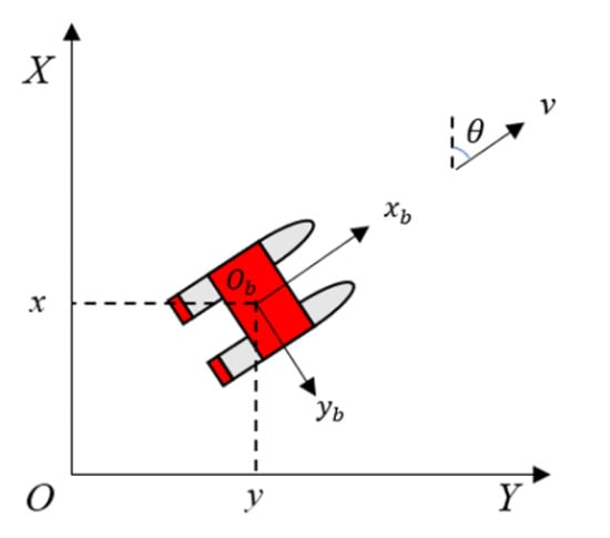
Figure 1.
Unmanned surface vehicle (USV) kinematic model.
2.2. Formation Definition
Figure 2 shows a diagram of the virtual structure method in which the thick dashed line denotes the shape outline of the virtual structure, while the USV dashed-line shape denotes the location distribution of each USV in the final formation. The formation implementation can be described by satisfying Equation (2):
where and represent the desired position and current position of the USV, respectively, and denotes the number of USVs in the formation.
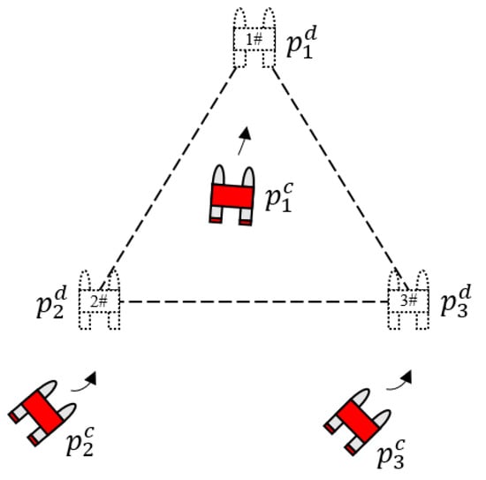
Figure 2.
Virtual structure method.
3. Algorithm Design
In this section, a formation control algorithm is proposed. The virtual structure method has the advantages of a clear geometric position relationship of members in the formation and high accuracy of formation keeping. On the other hand, the artificial potential field method has the advantage of a low computational complexity in collision avoidance research. Therefore, the algorithm of the combination of a virtual structure and artificial potential field is applied for formation control. A schematic diagram of the algorithm is shown in Figure 3. The black circle represents the formation reference point, the virtual structure is built around the formation reference point, the blue circle represents the point on the virtual structure, which is referred to as virtual structure point, and the orange circle represents the virtual leader. During the formation process, the path of the virtual structure depends on the formation reference point. Virtual leaders track their corresponding virtual structure points, while the USV accurately tracks the path of the virtual leader to achieve the desired formation.
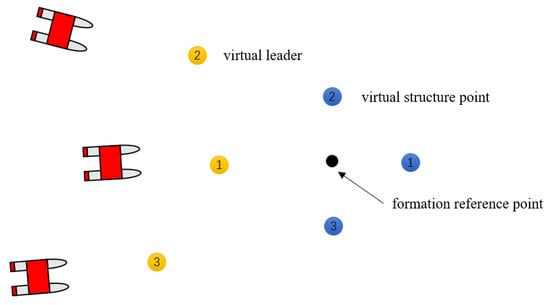
Figure 3.
Algorithm diagram.
3.1. Generation of the Virtual Structure
and represent the position and velocity vectors of the formation reference point in , respectively. The motion model of the formation reference point can be expressed by:
where represents the guidance control law related to formation path planning, according to which the formation reference point moves along the desired formation path.
denotes the location of the virtual structure point in . Its location in can be expressed by:
where and represent the transformation matrix from to and formation scaling matrix, respectively. They can be expressed as follows:
The reasons for the introduction of the virtual leader are as follows. In the initial stage, the USV is randomly distributed in the initialization area, which may be far away from the corresponding virtual structure point . If the USV directly drives to , collision between the USVs may occur. During the dynamic process, the effective control of the motion state of the USV will be lost. Similarly, during the process of formation transformation, the shape of the virtual structure changes from to . The corresponding expected formation trajectory will also have a step change. The USV changes from tracking the original formation trajectory to tracking the new formation trajectory, with a large position change. In this process, there are also problems of collision between USVs and control of the USV. Using a virtual leader and enabling the USV to track it, the movement state of the USV can be effectively controlled before the generation of the formation. Simultaneously, using the virtual leader as a medium, the introduction of the artificial potential field can avoid collisions between USVs.
The motion model of the virtual leader can be expressed by:
where and are the position and velocity of the virtual leader, respectively.
The control input of the virtual leader is:
where and are the position and velocity of the virtual structure point in , respectively. is the feedback coefficient of the position error, is the speed error feedback coefficient, and is the force term of the artificial potential field for collision avoidance, which is used to achieve collision avoidance between virtual leaders. As for collision avoidance between USVs, because USVs are randomly arranged near their corresponding virtual leader’s position in the initial stage, the USV only needs to track the corresponding virtual leader accurately to avoid collisions with each other. It is considered that the virtual leader is in the potential field generated by the neighboring virtual leaders. The total potential energy of the virtual leader can be expressed by:
where is the artificial potential field function, and denotes the vector modulus. As the artificial potential field is used to only avoid collision rather than organize the formation, the potential field only has repulsion, while the potential function is designed as:
where is the distance between virtual leaders and is the influence range of the artificial potential field. When the relative distance between virtual leaders is larger than , no interaction of artificial potential field forces exists. is the potential field gain coefficient, which should be selected to consider the actual performance of the USV. A very small value is not conducive to the safe collision avoidance of a USV, while a too large value may lead to the control input exceeding the capacity of the actuator. It is necessary to consider the possible interference to the formation in the design of the artificial potential field and choose the value of the potential field range as follows:
Thus, in the neighborhood of the final formation, the term of artificial potential field on the right side of Equation (8) can be eliminated. Equations (7) and (8) form a linear second-order system:
According to the Hurwitz theorem, the system is stable when , . As the tracking target of the USV, the virtual leaders should avoid violent movement to reduce the frequent maneuver of the USV. The smaller can avoid a too fast movement of the virtual leader to the formation reference point, and thus the speed tends to saturation. The larger can match the speed, which is convenient for a stable generation of the formation. The effect of the artificial potential field during the formation process can be considered as interference to the second-order system. Owing to the existence of a negative gradient term of the artificial potential field, virtual leaders move towards the direction where the artificial potential field can be reduced to achieve collision avoidance.
3.2. Formation Transformation
According to Equation (4), the velocity of the virtual structure point in can be expressed as:
Assuming that the transformation of the formation is achieved by a step change of , Equation (13) can be simplified to:
where represents the shape of the formation. During the formation movement, the formation switching can be achieved by changing the value of . represents the size of the virtual structure. The size of the formation can be changed by setting different values of .
3.3. Obstacle Avoidance
The USV formation inevitably needs to pass through the obstacle area during the movement. In some specific application scenarios, such as collaborative object transportation and collaborative area scanning operation, the USV formation is necessary to maintain the complete structure during the process of obstacle avoidance. In this section, we study the conformal obstacle avoidance algorithm for multi-USV formation.
3.3.1. Artificial Potential Field Method
The artificial potential field method is a common algorithm in robot obstacle avoidance research. The robot is in the force field generated by obstacles and target point, the target attracts the robot, the obstacles repel the robot, and the robot moves under the action of joint forces [,]. However, the algorithm has a defect of a local minimum value, which will lead to robot falling into a “dead point”. As the actual movement ability is not considered, the robot cannot accurately track the path planned by the algorithm. In practical application, it is often used in combination with other algorithms [,,].
3.3.2. Dynamic window approach
The dynamic window approach is a local path planning algorithm, which considers the dynamic performance of the USV [,]. Its implementation consists of two steps. The first step is to generate an effective search space, in which the performance constraints of the USV need to be fully considered. The second step is to select the best scheme in the search space.
- (1)
- Search spacex
In this step, every group of speed generated in the search space is tested to ensure that they can safely control the USV. The generation of speed instructions is limited by the speed and acceleration of the USV. Simultaneously, for safety, the USV should have enough obstacle avoidance distance during the process of movement. By comprehensively considering the above constraints, a feasible speed space is finally generated.
The USV has the ability to move forward and rotate. Moreover, the moving distance of the USV in the sampling period is limited. Therefore, the trajectory of the USV in the sampling period can be simplified to a straight line. The coordinate of the USV at time can be calculated, so that the trajectory of every set of velocities can be estimated. Therefore, the derivation formulas of the USV are:
where and are coordinates of the USV on the x-axis and y-axis of the world coordinate system, and are the linear and angular velocities of the USV, respectively, and is the heading of the USV at time .
In the velocity space , sets of velocity are sampled and every set corresponds to a simulated track, while the velocity sampling range needs to be determined according to the limitations of the property of the USV and environmental constraints.
The limitation of the maximum velocity and minimum velocity is:
where and represent the linear and angular velocities, respectively. and represent the maximum decelerations of the linear and angular velocities, respectively, while and represent the maximum accelerations of the linear and angular velocities, respectively.
Based on safe considerations, the USV needs to stop moving before hitting obstacles. The range of the speed of the USV under the maximum deceleration is:
where is the shortest distance from the USV to the obstacle on the corresponding trajectory of the velocity .
Thus, the actual sampling range of the USV speed is the intersection of the above three speed spaces:
- (2)
- Optimization
The purpose of this step is to obtain the optimal speed set and evaluate the speed set in the search space. In the original dynamic window approach, the definition of the evaluation function is:
where is the smoothing function, , , are constants, and is an index used to evaluate the alignment degree between the current direction and target direction of the USV at the current set sampling speed. represents the distance between the USV and nearest obstacle on the current track. If there is no obstacle on this track, it is set as a constant. is the position vector of the USV. The kinematic equation ofto evaluate the speed of the current track.
The original evaluation function can quickly guide the USV to the target position. However, when the USV approaches the target, the angle between the heading of the USV and target sharply increases. Under the function of the term in the evaluation function, the USV will then increase its angular velocity to reduce , which will make the motion of the USV insufficiently smooth. Therefore, the evaluation function needs to be improved.
- (3)
- Improved evaluation function
The evaluation function in the dynamic window approach is improved by importing the distance from the USV to the target. The improved evaluation function is as follows:
where is the distance from the current position of the USV to the target. The physical meaning of the other items is consistent with the evaluation function before the improvement. By the improved algorithm, the heading angle of the USV can converge to the target point more quickly and the obstacle avoidance time can be reduced, while ensuring the safety of obstacle avoidance.
3.4. USV Path Tracking Algorithm
The USV achieves the formation by tracking the corresponding virtual leader. Thus, it is necessary to design the corresponding tracking control algorithm for the USV.
In Figure 4, represents the current gesture information of the USV, represents the control input, and represents the desired gesture the of USV.
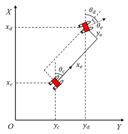
Figure 4.
USV tracking diagram.
The error formula is:
The tracking controller is designed as follows:
- (1)
- Velocity controller
Figure 4 shows that the distance between the current position and desired position of the USV is:
The speed controller of the USV is designed as:
- (2)
- Heading controller
The angle error of the USV during the tracking is:
To accurately track the desired heading by the USV, the Proportional Integral (PI) controller is used to control the angle. The designed heading angle control law is:
4. Numerical Simulations
Simulations are carried out to evaluate the algorithms proposed in this study.
4.1. Path Tracking Controller
Figure 5a, b shows the simulation results of the line path and circular path tracking, respectively. The arrow denotes the USV, while the black dotted line and red solid line represent the desired path and trajectory of the USV, respectively. The figures show that the USV can accurately track the desired path.
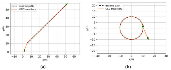
Figure 5.
USV path tracking results: (a) line path tracking; (b) circular path tracking.
4.2. Coordinated Path Tracking of Formation of Three USVs
Figure 6 shows the virtual structure of the formation, in which the black point and blue point represent the formation reference point and virtual structure point, respectively. The red circle denotes the force range of the potential field.
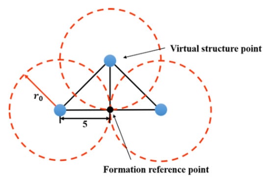
Figure 6.
Virtual structure.
4.2.1. Line Path Tracking
It is assumed that the initial positions of the virtual leaders and USVs are randomly distributed in the area of . Figure 7 shows the simulation results of the formation for line path tracking. The blue diamond in Figure 7a indicates the virtual leader, while the red triangle in Figure 7b indicates the USV. As shown in Figure 7, the virtual leaders can stably form the desired formation, while the USV achieves the formation by accurately tracking the corresponding virtual leader. As shown in Figure 8, the distances between the neighboring USVs are maintained at 7.07 and 10 m, consistent with the distance between preset virtual structure points.
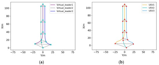
Figure 7.
USV formation line path tracking results: (a) virtual leader trajectory; (b) USV trajectory.
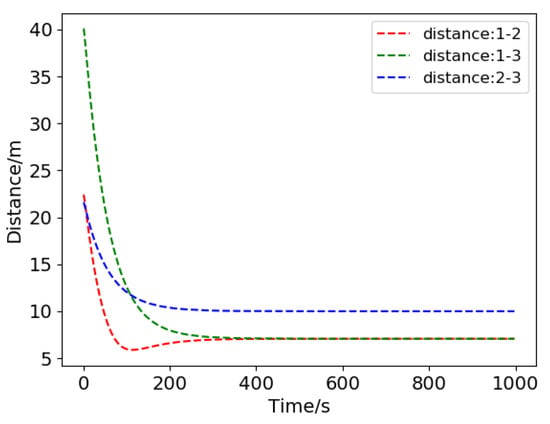
Figure 8.
Distance between the neighboring USVs.
4.2.2. Curve Path Tracking
Another typical tracking case is curve path tracking. Assuming that the initial positions of the virtual leaders and USVs are randomly distributed in the area of , Figure 9 shows the simulation results of the formation for curve path tracking. As shown in Figure 10, the distances between the neighboring USVs are maintained at 7.07 and 10 m. Figure 9 and Figure 10 show that the three USVs achieve the desired formation shape and that the formation can accurately track the curve path.
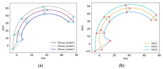
Figure 9.
USV formation curve path tracking results: (a) virtual leader trajectory; (b) USV trajectory.
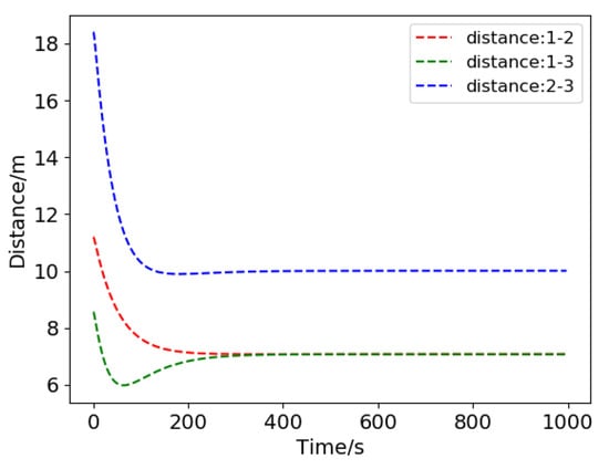
Figure 10.
Distances between the neighboring USVs.
4.3. Formation Scalability
The scalability of the number of formation members is an important index to evaluate the formation control algorithm. The algorithm proposed in this study can adjust the number of formation members according to the mission requirements. Formation generation simulation of four and six USVs are carried out.
Figure 11 shows the virtual structure of the four-USV formation. Assuming that the shape of the virtual structure is a square, the centroid of the square is selected as the formation reference point, while the distance between each virtual structure point and formation reference point is 5 m. Assuming that the force range of the potential field is set to 5 m, the initial positions of the virtual leaders and USVs are randomly distributed in the area of .
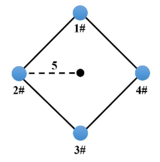
Figure 11.
Virtual structure.
Figure 12 shows the simulation results of the four-USV formation generation. Figure 13 shows that the distances between each USV and formation reference point are maintained at 5 m, consistent with the distance designed in the virtual structure.
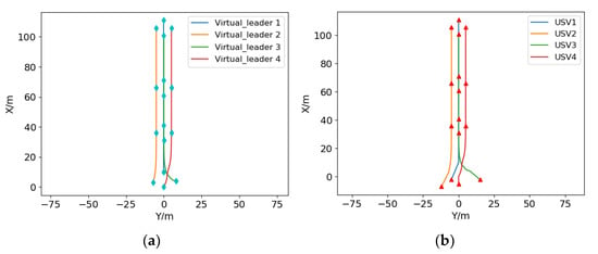
Figure 12.
Four-USV formation generation simulation results: (a) virtual leader trajectory; (b) USV trajectory.
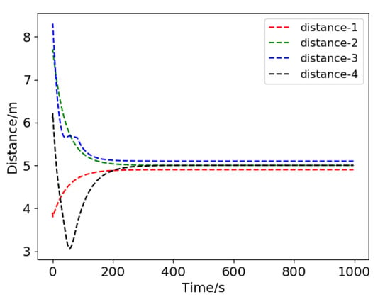
Figure 13.
Distance between USVs and formation reference point.
Figure 14 shows the virtual structure of the six-USV formation. The shape of the virtual structure is an isosceles right triangle. Assuming that the virtual structure points are located at the vertex and midpoint of each side of the triangle, the formation reference point coincides with the fifth virtual structure point. The force range of the potential field is set to 5 m, assuming that the initial positions of the virtual leaders and USVs are randomly distributed in the area of .
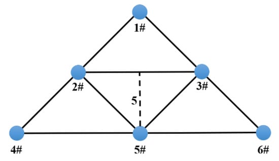
Figure 14.
Virtual structure.
Figure 15 shows the simulation results of the four-USV formation generation. Figure 16 shows that the distances between each USV and the formation reference point are maintained at 10, 7.07, and 0 m, consistent with the distance designed in the virtual structure.
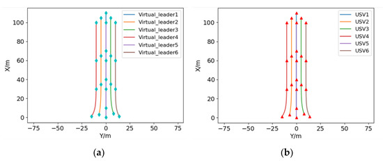
Figure 15.
Six-USV formation generation simulation results: (a) virtual leader trajectory; (b) USV trajectory.
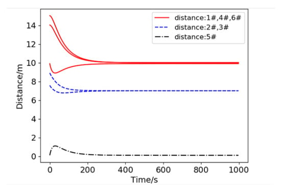
Figure 16.
Distance between USVs and formation reference point.
4.4. Formation Shape Transformation
4.4.1. Structure Change
The change in the formation structure is achieved by setting different values in Equation (14). It is assumed that three USVs are randomly distributed at the initial time, forming a triangle shape first, then switching to the line shape, and finally returning to the triangle shape.
Figure 17 shows that during the period of 0–100 s, the USVs gradually form the triangle formation structure from the random distribution state. The relative distances between USVs are maintained during the movement in the period of 100–200 s movement. After 200 s, the formation structure starts to change. The distances between the USVs gradually stabilize to new values. After moving a certain distance, the formation starts to switch and eventually returns to the original triangle formation.
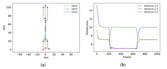
Figure 17.
USV formation structure change results: (a) USV trajectory; (b) distance between the neighboring USVs.
4.4.2. Structure Scaling
The scaling of the formation configuration is achieved by setting different values in Equation (14). It is assumed that three USVs are randomly distributed at the initial time. The distance between each virtual structure point and formation reference point is expected to be 5 m. The USV gradually forms a triangle formation from the random distribution state. After moving a certain distance, the formation scale gradually reduces to 0.7 times the initial state, and then gradually returns to the initial state value. Figure 18a, b shows the trajectories of the USVs and relative distances between the USVs during the process, respectively.
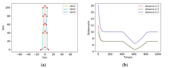
Figure 18.
USV formation structure scaling results: (a) USV trajectory; (b) distance between neighboring USVs.
4.5. Dynamic Window Approach
Assuming that the simulation parameters such as starting point information, target point information, and obstacle information are consistent, the paths generated by the original approach and improved approach are compared.
Figure 19 shows the simulation results of local path planning of the dynamic window approach. As is seen in Figure 19, after the improvement of the evaluation function, the USV can keep a safe distance from the obstacles and move in a shorter path, which saves moving time. After avoiding the obstacles, the improved algorithm can make the USV’s heading angle converge to the target point faster, so as to ensure that the USV can reach the target faster.
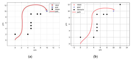
Figure 19.
Dynamic window approach: (a) path planned by the original approach; (b) path planned by the improved approach.
4.6. Formation Obstacle Avoidance
Figure 20 shows a diagram of the obstacle avoidance strategy. The USV formation maintains its shape during the obstacle avoidance process. In this study, the strategy of applying the improved dynamic window approach to the formation reference point is used. In this strategy, the whole formation is regarded as a larger-scale USV centered on the formation reference point. Using this method, the formation reference point can plan a favorable path for USVs to avoid obstacles.
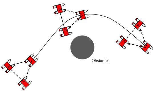
Figure 20.
Diagram of the obstacle avoidance strategy.
Assuming that the distance between each USV and formation reference point is 5 m, the target point is located at (50, 50), the obstacle is located at (20, 20), and the radius of the obstacle is 4 m.
Figure 21 shows the simulation results of the formation obstacle avoidance. Compared to the results in [], where the artificial potential field for multi-AUV systems is used to achieve obstacle avoidance, the path planned by our algorithm is smoother and more executable for actual vehicles. As shown in Figure 22, all USVs are at a safe distance from the obstacle, which demonstrates that the algorithm is able to generate acceptable safe paths in an obstacle environment. Furthermore, as shown in Figure 22a, the distances between the obstacle and each USV are recorded. Notably, the smallest distance between the USV and obstacle is 5 m. The relative distances between the USVs are shown in Figure 22b. The formation shape can be well maintained as the distance fluctuations remain relatively small.
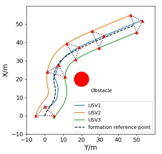
Figure 21.
Formation obstacle avoidance path.
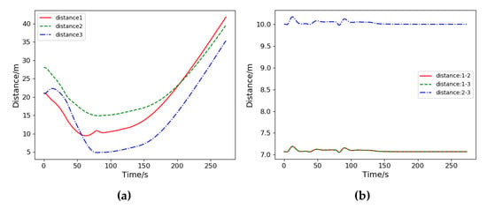
Figure 22.
Distance during the process of obstacle avoidance: (a) distance between USVs and obstacle; (b) distance between the neighboring USVs.
5. Conclusions
In this study, the formation control algorithm of a multi-USV system and problem of conformal obstacle avoidance are investigated. The algorithm combining the virtual structure and artificial potential field can effectively organize USVs to generate the desired formation and flexibly change the formation shape by structure switching and scaling strategies. Through the improved dynamic window approach, the formation reference point can plan a safe obstacle avoidance path for the formation, and thus the formation can maintain the shape while avoiding the obstacle. Compared to the traditional artificial potential field method, the proposed method is more conducive because it considers the actual execution ability of the USV. Finally, the numerical simulation results validated the effectiveness of the proposed formation control algorithm.
Author Contributions
Conceptualization, X.Y. and D.J.; methodology, X.Y. and R.M.; software, X.Y.; validation, X.Y. and R.M.; formal analysis, X.Y.; investigation, X.Y. and R.M.; resources, D.J. and Y.L.; data curation, X.Y.; writing—original draft preparation, X.Y.; writing—review and editing, D.J.; visualization, X.Y.; supervision, D.J.; project administration, D.J.; funding acquisition, D.J. All authors have read and agreed to the published version of the manuscript.
Funding
This research was funded by the Foundation of Pre-research on Military Equipment of the Chinese People’s Liberation Army (No.6140241010103; JZX7Y20190252032901).
Institutional Review Board Statement
No applicable.
Informed Consent Statement
No applicable.
Conflicts of Interest
The authors declare no conflict of interest. The funders had no role in the design of the study; in the collection, analyses, or interpretation of data; in the writing of the manuscript, or in the decision to publish the results.
References
- Zaghi, S.; Dubbioso, G.; Broglia, R.; Muscari, R. Hydrodynamic Characterization of USV Vessels with Innovative SWATH Configuration for Coastal Monitoring and Low Environmental Impact. Transp. Res. Procedia 2016, 14, 1562–1570. [Google Scholar] [CrossRef]
- Shriyam, S.; Shah, B.C.; Gupta, S.K. Decomposition of Collaborative Surveillance Tasks for Execution in Marine Environments by a Team of Unmanned Surface Vehicles. J. Mech. Robot. 2018, 10, 025007. [Google Scholar] [CrossRef]
- Do, N.M.; Nguyen, P.H.; Nguyen, D.A. Design and Simulate a Fuzzy Autopilot for an Unmanned Surface Vessel. In Proceedings of the 2017 International Conference on System Science and Engineering (ICSSE), Ho Chi Minh, Vietnam, 21–23 July 2017; pp. 454–459. [Google Scholar]
- Nantogma, S.; Ran, W.; Yang, X.; Xiaoqin, H. Behavior-Based Genetic Fuzzy Control System for Multiple USVs Cooperative Target Protection. In Proceedings of the 2019 3rd International Symposium on Autonomous Systems (ISAS), Shanghai, China, 29–31 May 2019; pp. 181–186. [Google Scholar]
- Do, K.D. Bounded Controllers for Formation Stabilization of Mobile Agents with Limited Sensing Ranges. IEEE Trans. Autom. Control. 2007, 52, 569–576. [Google Scholar] [CrossRef]
- Tanner, H.G.; Kumar, A. Towards Decentralization of Multi-Robot Navigation Functions. In Proceedings of the 2005 IEEE International Conference on Robotics and Automation, Barcelona, Spain, 18–22 April 2005; pp. 4132–4137. [Google Scholar]
- Hu, J.; Feng, G. Distributed tracking control of leader–follower multi-agent systems under noisy measurement. Automatica 2010, 46, 1382–1387. [Google Scholar] [CrossRef]
- Yuan, C.; He, H.; Wang, C. Cooperative Deterministic Learning-Based Formation Control for a Group of Nonlinear Uncertain Mechanical Systems. IEEE Trans. Ind. Inform. 2018, 15, 319–333. [Google Scholar] [CrossRef]
- Zhang, Q.; Lapierre, L.; Xiang, X. Distributed control of coordinated path tracking for networked nonholonomic mobile vehi-cles. IEEE Trans. Ind. Inform. 2012, 9, 472–484. [Google Scholar] [CrossRef]
- Balch, T.; Arkin, R. Behavior-based formation control for multirobot teams. IEEE Trans. Robot. Autom. 1998, 14, 926–939. [Google Scholar] [CrossRef]
- Xu, D.; Zhang, X.; Zhu, Z.; Chen, C.; Yang, P. Behavior-Based Formation Control of Swarm Robots. Math. Probl. Eng. 2014, 2014, 1–13. [Google Scholar] [CrossRef]
- Gazi, V.; Fidan, B.; Ordóñez, R.; İlter Köksal, M. A target tracking approach for nonholonomic agents based on artificial po-tentials and sliding mode control. J. Dyn. Syst. Meas. Control. 2012, 134, 1–13. [Google Scholar] [CrossRef]
- Zavlanos, M.M.; Egerstedt, M.B.; Pappas, G.J. Graph-theoretic connectivity control of mobile robot networks. Proc. IEEE 2011, 99, 1525–1540. [Google Scholar] [CrossRef]
- Sun, X.; Wang, G.; Fan, Y.; Mu, D.; Qiu, B. A formation collision avoidance system for unmanned surface vehicles with leader-follower structure. IEEE Access 2019, 7, 24691–24702. [Google Scholar] [CrossRef]
- Ghommam, J.; Saad, M. Adaptive Leader–Follower Formation Control of Underactuated Surface Vessels Under Asymmetric Range and Bearing Constraints. IEEE Trans. Veh. Technol. 2017, 67, 852–865. [Google Scholar] [CrossRef]
- Peng, Z.; Wang, J.; Wang, D. Distributed Maneuvering of Autonomous Surface Vehicles Based on Neurodynamic Optimization and Fuzzy Approximation. IEEE Trans. Control. Syst. Technol. 2018, 26, 1083–1090. [Google Scholar] [CrossRef]
- Shi, Q.; Li, T.; Yang, S.; Li, J.; Wu, Y. Adaptive Leader-Follower Formation Control of Unmanned Surface Vessels with Obstacle Avoidance. In Proceedings of the 30th International Ocean and Polar Engineering Conference, Virtual, 11–16 October 2020. [Google Scholar]
- Liang, X.; Qu, X.; Hou, Y.; Li, Y.; Zhang, R. Distributed coordinated tracking control of multiple unmanned surface vehicles under complex marine environments. Ocean Engineering. 2020, 205, 107328. [Google Scholar] [CrossRef]
- Park, B.S.; Yoo, S.J. An Error Transformation Approach for Connectivity-Preserving and Collision-Avoiding Formation Tracking of Networked Uncertain Underactuated Surface Vessels. IEEE Trans. Cybern. 2019, 49, 2955–2966. [Google Scholar] [CrossRef]
- Liu, L.; Wang, D.; Peng, Z.; Li, T.; Chen, C.L.P. Cooperative Path Following Ring-Networked Under-Actuated Autonomous Surface Vehicles: Algorithms and Experimental Results. IEEE Trans. Cybern. 2018, 50, 1519–1529. [Google Scholar] [CrossRef] [PubMed]
- Jia, Q.; Li, G. Formation Control and Obstacle Avoidance Algorithm of Multiple Autonomous Underwater Vehicles (AUVs) Based on Potential Function and Behavior Rules. In Proceedings of the 2007 IEEE International Conference on Automation and Logistics, Jinan, China, 18–21 August 2007; pp. 569–573. [Google Scholar]
- Kang, X.; Xu, H.; Feng, X. Fuzzy Logic Based Behavior Fusion for Multi-AUV Formation Keeping in Uncertain Ocean Environment. In Proceedings of the OCEANS 2009, Bremen, Germany, 11–14 May 2009; pp. 1–7. [Google Scholar]
- Bian, J.; Xiang, J. Three-Dimensional Coordination Control for Multiple Autonomous Underwater Vehicles. IEEE Access 2019, 7, 63913–63920. [Google Scholar] [CrossRef]
- Jin, X. Fault tolerant finite-time leader–follower formation control for autonomous surface vessels with LOS range and angle constraints. Automatica 2016, 68, 228–236. [Google Scholar] [CrossRef]
- Wang, D.; Fu, M. Adaptive formation control for waterjet USV with input and output constraints based on bioinspired neu-rodynamics. IEEE Access 2019, 7, 165852–165861. [Google Scholar] [CrossRef]
- He, S.; Wang, M.; Dai, S.-L.; Luo, F. Leader–Follower Formation Control of USVs With Prescribed Performance and Collision Avoidance. IEEE Trans. Ind. Inform. 2019, 15, 572–581. [Google Scholar] [CrossRef]
- Kamel, M.A.; Yu, X.; Zhang, Y. Fault-Tolerant Cooperative Control Design of Multiple Wheeled Mobile Robots. IEEE Trans. Control. Syst. Technol. 2017, 26, 756–764. [Google Scholar] [CrossRef]
- Veelaert, P.; Bogaerts, W. Ultrasonic potential field sensor for obstacle avoidance. IEEE Trans. Robot. Autom. 1999, 15, 774–779. [Google Scholar] [CrossRef]
- Zhou, L.; Li, W. Adaptive Artificial Potential Field Approach for Obstacle Avoidance Path Planning. In Proceedings of the 2014 Seventh International Symposium on Computational Intelligence and Design (ISCID 2014), Hangzhou, China, 13–14 December 2014; IEEE: Piscataway, NJ, USA, 2014; Volume 2, pp. 429–432. [Google Scholar]
- Li, X.; Fang, Y.; Fu, W. Obstacle Avoidance Algorithm for Multi-UAV Flocking Based on Artificial Potential Field and Dubins Path Planning. In Proceedings of the 2019 IEEE International Conference on Unmanned Systems (ICUS), Beijing, China, 17–19 October 2019; pp. 593–598. [Google Scholar]
- Ying, Z.; Xu, L.; Zhang, Y. Leader-Follower Formation Control and Obstacle Avoidance of Multi-Robot Based on Artificial Potential Field. In Proceedings of the 27th Chinese Control and Decision Conference (2015 CCDC), Qingdao, China, 23–25 May 2015; pp. 4355–4360. [Google Scholar]
- Nair, R.R.; Behera, L.; Kumar, V.; Jamshidi, M. Multisatellite Formation Control for Remote Sensing Applications Using Artificial Potential Field and Adaptive Fuzzy Sliding Mode Control. IEEE Syst. J. 2014, 9, 508–518. [Google Scholar] [CrossRef]
- Ogren, P.; Leonard, N. A convergent dynamic window approach to obstacle avoidance. IEEE Trans. Robot. 2005, 21, 188–195. [Google Scholar] [CrossRef]
- Ballesteros, J.; Urdiales, C.; Velasco, A.B.M.; Ramos-Jimenez, G. A Biomimetical Dynamic Window Approach to Navigation for Collaborative Control. IEEE Trans. Hum. Mach. Syst. 2017, 47, 1123–1133. [Google Scholar] [CrossRef]
- Pan, W.W. Study on Distributed Formation Control of Multiple Autonomous Underwater Vehicles. Ph.D. Thesis, Harbin Engineering University, Heilongjiang, China, 2018. [Google Scholar]
Publisher’s Note: MDPI stays neutral with regard to jurisdictional claims in published maps and institutional affiliations. |
© 2021 by the authors. Licensee MDPI, Basel, Switzerland. This article is an open access article distributed under the terms and conditions of the Creative Commons Attribution (CC BY) license (http://creativecommons.org/licenses/by/4.0/).