Article

RANS Prediction of Wave-Induced Ship Motions, and Steady Wave Forces and Moments in Regular Waves

1
Key Laboratory of High-Performance Ship Technology, Wuhan University of Technology, Ministry of Education, Wuhan 430070, China
2
School of Naval Architecture, Ocean and Energy Power Engineering, Wuhan University of Technology, Wuhan 430070, China
*
Authors to whom correspondence should be addressed.
J. Mar. Sci. Eng. 2021, 9(12), 1459; https://doi.org/10.3390/jmse9121459
Submission received: 26 November 2021 / Revised: 16 December 2021 / Accepted: 16 December 2021 / Published: 20 December 2021
(This article belongs to the Special Issue Ship Dynamics and Hydrodynamics)

Abstract

:
The wave-induced motions, and steady wave forces and moments for the oil tanker KVLCC2 in regular head and oblique waves are numerically predicted by using the expanded RANS solver based on OpenFOAM. New modules of wave boundary condition are programed into OpenFOAM for this purpose. In the present consideration, the steady wave forces and moments include not only the contribution of hydrodynamic effects but also the contribution of the inertial effects due to wave-induced ship motions. The computed results show that the contribution of the inertial effects due to heave and pitch in head waves is non-negligible when wave-induced motions are of large amplitude, for example, in long waves. The influence of wave amplitude on added resistance in head waves is also analyzed. The dimensionless added resistance becomes smaller with the increasing wave amplitude, indicating that added resistance is not proportional to the square of wave amplitude. However, wave amplitude seems not to affect the heave and pitch RAOs significantly. The steady wave surge force, sway force and yaw moment for the KVLCC2 with zero speed in oblique waves are computed as well. The present RANS results are compared with available experimental data, and very good agreements are found between them.

1. Introduction

Nowadays, environmental issues have become more and more prominent. Green, efficient and sustainable development has become the main theme of human development. There is a greater need to reduce pollution emissions and save energy for ships operated in real sea conditions. The International Maritime Organization (IMO) and the Marine Environmental Protection Commission (MEPC) have released the regulations for ship energy efficiency standards, for example, the Energy Efficiency Design Index (EEDI) [1,2], which strictly regulates greenhouse gas emissions for newly-built ships. Ship added resistance is closely related to the calculation of the speed reduction coefficient ( f w ) in the estimation formula of EEDI. The IMO has also developed guidelines for minimum propulsion power to ensure ship maneuverability in adverse weather conditions [3] to ensure safe navigation. On one hand, the development of green ship technology requires ships to use equipment with less power to reduce emissions and meet energy efficiency standards. On the other hand, ships will inevitably be affected by various environmental factors in sailing, and ships are required to have sufficient propulsion power to cope with the harsh environment and ensure navigation safety. It needs to seek a balance between the two sides. Therefore, it is necessary to accurately forecast a ship’s navigational performance in the actual sea environment at the initial stage of design.
When sailing in waves, the steady forces and moments acting on the ship will increase, for example, the added resistance, compared with that in calm water. The towing tank test is regarded as the most accurate way to determine the added forces and moments due to waves, for example, in the works of Sadat-Hosseini et al. [4] and Lee et al. [5]. In recent years, a large number of towing tank tests have been carried out to investigate the hydrodynamic performance of various ships in waves in the frame of the European Union project SHOPERA [6].
However, the towing tank test is usually of high cost, and needs a long preparation period. In addition, it is not so helpful for a theoretical understanding of the problem. Therefore, numerical methods are more and more popularly applied to studying ship hydrodynamic performance at present. Perhaps the numerical methods used nowadays for ship hydrodynamic performance in waves can be categorized into two methods. One is based on potential flow theory, and the other is based on viscous flow theory. There are two main approaches based on potential flow theory, that is, the near-field method and the far-field method. The near-field method directly integrates pressure on the hull surface. Havelock [7] might be the first one who focused on the problem of ship added resistance. He derived the formula of the added resistance without considering the diffraction action of waves based on the Froude–Krylova hypothesis. Salvesen [8] introduced a simplified asymptotic method based on two-dimensional strip theory to overcome the shortcomings of this method in short waves. Faltinsen et al. [9] improved the near-field method based on the direct pressure integration method. Kim et al. [10] developed a three-dimensional time-domain method to predict ship added resistance based on the near-field method. The far-field method is based on the conservation of energy, by which ship added resistance is calculated by the wave energy and momentum fluxes around the hull. This method was proposed by Mauro [11] at first. Joosen [12] and Newman [13] also used this method to predict the added resistance and wave drift force. Later on, Gerritsma and Beukelman [14] improved the far-field method based on the radiated energy method to predict the added resistance in head waves. Chizhiumov [15] used a boundary element method to model the ship motion in heave sea conditions.
In recent years, the three-dimensional panel method has become popular when using the method based on potential flow theory. Kim et al. [16] computed the added resistance for the container ship S175 by using different numerical methods, that is, strip theory, 3D time-domain panel method, and CFD method. Their results indicated that all the numerical results could predict well ship added resistance, but the results from the 3D time-domain panel method and the CFD method have better accuracy than those with strip theory. Park et al. [17] predicted the added resistance of KVLCC2 under four different draft conditions based on the strip theory and the Rankine panel method. The prediction results of pitch and heave under different draft conditions with the two numerical methods were in good agreement with the experimental data.
The methods based on potential flow theory ignore the viscosity, and may not be appropriate for the strong non-linear problems. Yasukawa et al. [18] carried out an experimental study to investigate the effects of wave amplitude on added resistance, and two amplitudes were considered in the experiment. They found that ship added resistance was not proportional to the square of the wave amplitude, while wave amplitude had very little influence on heave and pitch RAOs (Response Amplitudes Operators). Lee et al. [19] and Yu et al. [20] also found similar conclusions in their studies. With the rapid development of computer performance, the numerical methods based on viscosity flow theory, especially the Reynolds-Average Navier–Stokes (RANS) method, are more and more widely used for the computation of ship hydrodynamic forces and moments in waves.
Guo et al. [21] used the RANS method to numerically predict the wave-induced motions and added resistance for KVLCC2 in head waves, and the numerical results were verified and confirmed by uncertainty analysis. The study showed that when λ / L p p < 0.6 , heave and pitch are of small values. Wu et al. [22] calculated the added resistance for KVLCC2 in head short waves by RANS, and the numerical results are in good agreement with the experimental values. They found that the increase of pressure near the ship’s bow contributed the most to the increase of resistance. Kim et al. [23] used both RANS and the potential flow method to predict ship added resistance, and validated the accuracy of the RANS method. They also used the RANS method to study speed drop. Sigmund et al. [24] used the RANS method to predict added resistance, and found that the contribution of viscosity accounted for 30% of the total added resistance in the short-wave conditions. The predicted results were in good agreement with the experimental data. Uharek et al. [25] used RANS code Neptuno to predict steady wave forces and moments for a ship in oblique regular waves. The study proved that the inertia effects due to wave-induced motions could not be ignored, especially in long waves. Lee et al. [26] used the RANS method to calculate the added resistance and propeller wake. Islam et al. [27] predicted ship resistances for four different ship models, and uncertainty analysis was performed. Yao et al. [28] numerically predicted added resistance and ship motion of oil tanker KVLCC2 by using RANS method. The effects of wavelength, wave amplitude and the scales of the ship model on the results were analyzed. Islam et al. [29] determined the propulsion power for an inland container vessel in open and restricted channel for a ship model and a full-scale ship. The simulated results indicated that the channel current was essential while predicting the propulsion power requirement and full-scale simulation was crucial for particular cases. Jiao et al. [30] predicted a nonlinear hydro-elastic response for S-175 by the CFD–FEA two-way coupling method in severe wave conditions. The results indicated that the simulation method was reliable and had broad applicability for ship seakeeping and hydro-elasticity issues. Yao et al. [31] computed the mean forces, moments and wave-induced six-DOF motions for KVLCC2 in the regular head wave and beam waves with the RANS method, and good agreement was shown by comparing the CFD results with the experimental data. The RANS method is gradually being widely used to investigate ship hydrodynamic performance in waves with the development of high-performance computing.
In this work, the wave-induced motions and added resistance are predicted for KVLCC2 performing straight ahead motion in head regular waves by using the expanded RANS solver based on OpenFOAM. Great efforts are devoted to the implement of new modules of wave boundary conditions. The steady wave forces and moments are also computed for the ship with zero speed in oblique waves. The added resistance, steady wave drift forces and moments include the contributions of hydrodynamic effects and inertial effects due to wave-induced motions. The results show reasonable agreements with experimental data. In addition, the effects of wavelength and wave amplitude are investigated. The present works would supply a good reference for ship control [32].

2. Numerical Method

2.1. Governing Equations and Numeric Discretization

A horizontal coordinate system is used to describe the flow around the ship. When the ship is at rest in still water, the origin locates at midship, x-axis towards bow, y-axis towards starboard, and z-axis vertical downwards (see Figure 1). Based on the assumption of incompressible Newtonian fluid, the mass conservation equation and momentum conservation (RANS) equations can be expressed as:
U i x i = 0
U i t + U i U j x j = 1 ρ p x i + x j v U i x j + U j x i U i U j ¯ ,
where x i = x , y , z are the Cartesian coordinates, U i = U , V , W is flow velocity components, ρ is the fluid density, p is pressure, v is kinematic viscosity coefficient, and ρ U i U j ¯ is the Reynolds stress tensor. The available method of mesh deformation is applied to allow the ship to perform motions in waves. In the present consideration, the ship is free to heave, pitch and roll, whereas surge is restrained by using a spring, and sway and yaw are completely fixed.
According to the Boussinesq hypothesis, the specific Reynolds stress can be expressed as:
U i U j ¯ = v t U i x j + U j x i 2 3 δ i j k ,
where v t is the eddy viscosity, k is the turbulent kinetic energy, and δ i j is the Kronecker symbol.
The eddy viscosity in Equation (3) is approximated by the SST k ω turbulence model. Since the turbulence transportation equations can be found everywhere, we do not repeat them here.
The Volume of Fluid (VOF) method is used to capture the free surface. The governing equation of volume fraction is:
F t + F U i x i = 0 ,
where F = 0 means the grid cell is full of air, F = 1 means the grid cell is full of water, and 0 < F < 1 means the grid cell locates at the interface between air and water. The mixed density and viscosity coefficients are expressed as follows
ρ = F ρ w + 1 F ρ a
v = F v w + 1 F v a
where subscripts w and a denote water and air respectively.
The Finite Volume Method (FVM) is used to solve the governing equations of fluid dynamics. The convection terms in the RANS equations and turbulence equations are discretized by Upwind Difference Scheme (UDS), the diffusion term in the RANS equations is discretized using Central Difference Scheme (CDS), and the time term is discretized using a second-order backward scheme. The PIMPLE algorithm is used to correct pressure, where the PIMPLE algorithm is the combination of the Simple (Semi-Implicit Method for Pressure-linked Equations) algorithm and PISO (Pressure Implicit with Split-of-operators) algorithm. For the system of linear equations, the Gauss–Seidel method is used to solve the velocity, turbulent kinetic energy, and dissipation rate iteratively, and the GAMG (Generalized Multi-Grid) method is used to solve the pressure iteratively.

2.2. The Expression of Steady Wave Force and Moment

During the present computations, the heave, pitch and roll are free; however, the surge is restricted by virtual spring, and sway and yaw are fixed, as mentioned. The added resistance, steady sway force and yaw moment are calculated by the following formulas:
F x ¯ = X ¯ X 0 + m w q ¯ + m u ˙ ¯ m g T ¯ 31
F y ¯ = Y ¯ + m w p ¯ + m g T ¯ 32
M z ¯ = N ¯ I y I x p q ¯ ,
where X ¯ , Y ¯ and N ¯ are the mean force or moment, which are obtained by integrating pressure and viscous stress over hull surface; X 0 is the clam-water resistance; X ¯ X 0 is added resistance due to the contribution of pure hydrodynamic effects; m w q ¯ and m w p ¯ are the mean inertia forces due to the coupled motions of heave, pitch and roll; m u ˙ ¯ is mean inertia force due to the surge acceleration; T is the transformation matrix, and T 31 is the component at the third row of first column; m g T ¯ 31 and m g T ¯ 32 are the mean inertial forces due to gravity. Their dimensionless forms are expressed as:
C F x = F x ¯ ρ g A 2 B 2 / L p p
C F x = F y ¯ ρ g A 2 B 2 / L p p
C M z = M z ¯ ρ g A 2 B 2 ,
where A is the wave amplitude; B is the ship beam; L p p is the length between perpendiculars.

2.3. Grid and Boundary Conditions
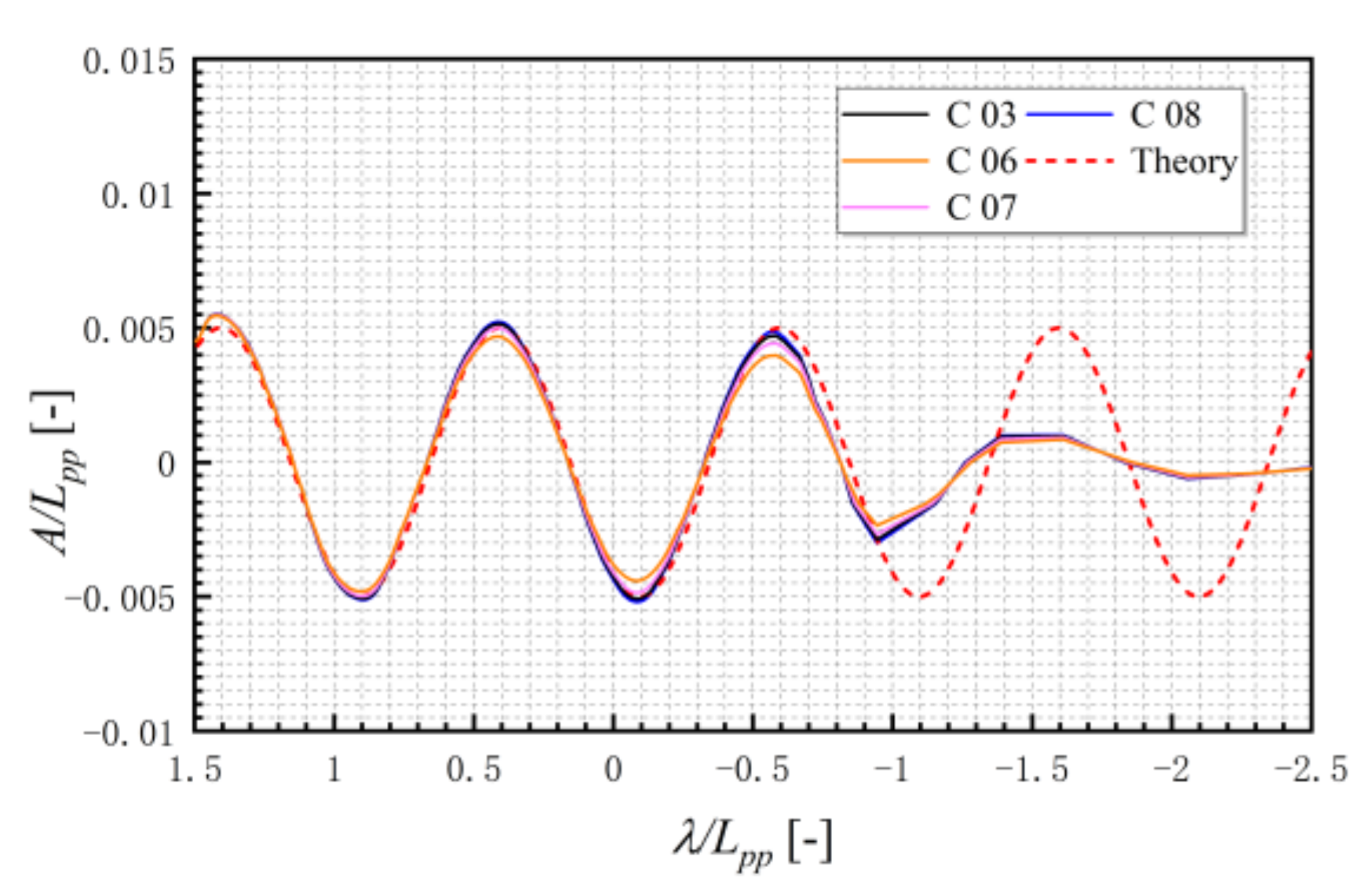
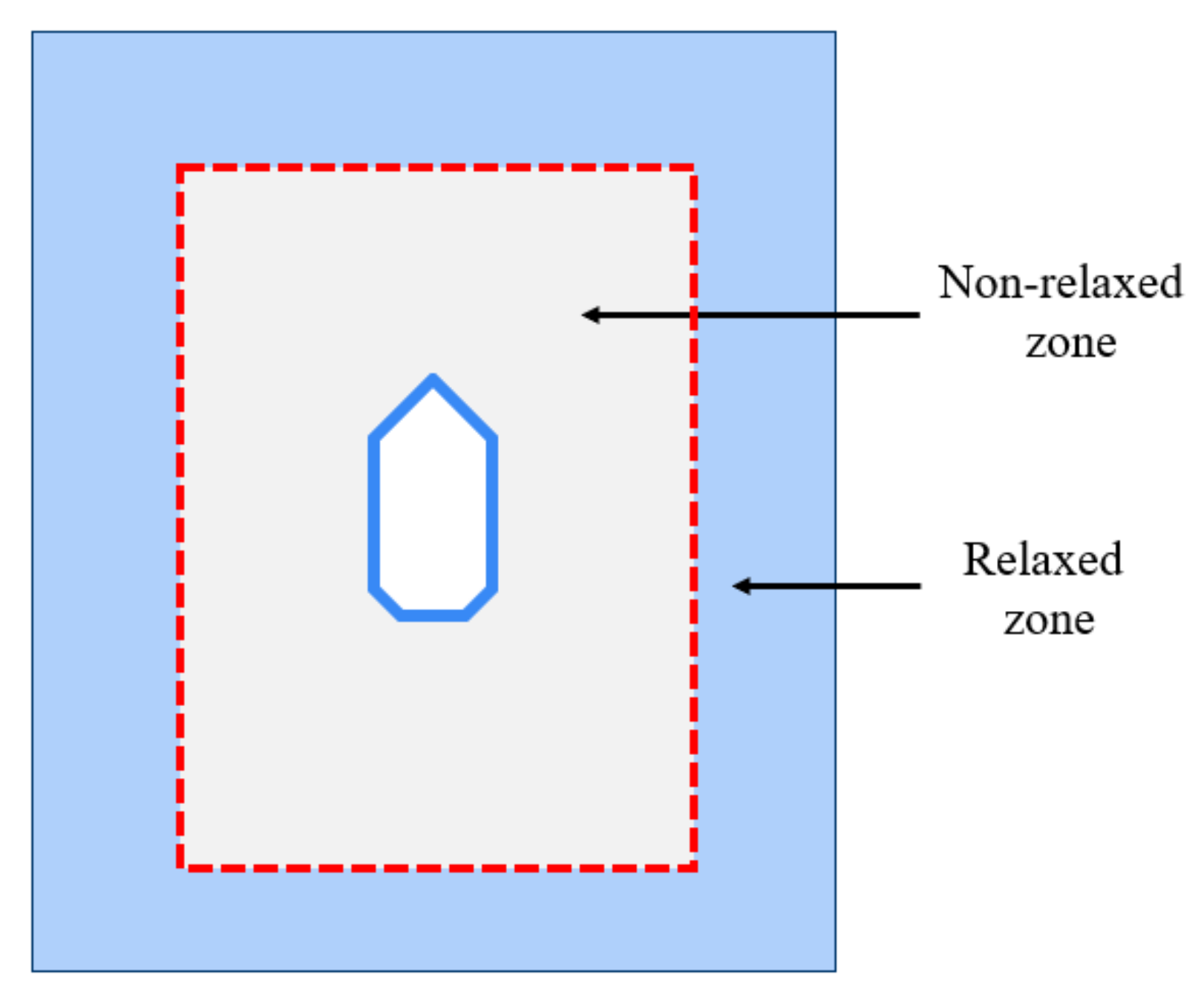
Due to symmetric flow, only a half ship is considered for head wave cases. The computational domains for head waves and oblique waves are shown in Figure 2a and Figure 3a, respectively. For head wave cases, the velocity inlet boundary condition is set at x = 1.5   L p p , the outlet boundary condition is set at x = 2.5   L p p , the symmetry boundary condition is set at y = 0 , and others are set as slip boundaries. For oblique wave cases, the boundaries at x = 1.5   L p p and y = L p p are set as velocity inlet boundaries, the boundaries at x = 1.5   L p p and y = 1   L p p are set as an outlet boundary, and others are set as slip boundaries.
The software Hexpress is used to generate computational grids. Figure 2b and Figure 3b show the grids for head wave cases and oblique wave cases, respectively. The wall function is used to approximate the flow near the hull surface and the dimensionless distance y + is in the range of 30~300.
In this study, wave generation in the computational domain is achieved by setting flow velocity on the inlet boundary. New modules of wave boundary conditions are programed into OpenFOAM. The flow velocity on the inlet boundary is the combination relative flow velocity relative to ship and wave orbital velocity from the solution of the potential theory of linear waves. The components of freestream flow velocity can be expressed as:
u w = u 0 A ω 0 cos h k w h z sin h k w h sin ω e t + k w x cos χ + k w y sin χ cos χ
v w = A ω 0 cos h k w h z sin h k w h sin ω e t + k w x cos χ + k w y sin χ sin χ
w w = A ω 0 sin h k w h z sin h k w h cos ω e t + k w x cos χ + k w y sin χ ,
where u 0 is the ship forward speed; h is water depth; k w is wave number; A is wave amplitude; ω 0 is natural frequency; χ is the angel of wave direction; ω e is encounter frequency and it is expressed by:
ω e = ω 0 + k w u 0 .
The ω 0 is
ω 0 = g k w tan h k w h .
The corresponding freestream wave evaluation is expressed as:
ζ = A sin ω e t + k w x cos χ + k w y sin χ .
For the cases in head waves, χ equals to zero, so that the Equations (13)–(15) and Equation (18) become:
u w = A ω 0 cos h k w h z sin h k w h sin ω e t + k w x
v w = 0
w w = A ω 0 sin h k w h z sin h k w h cos ω e t + k w x
ζ = A sin ω e t + k w x .

2.4. Wave Absorbing

The wave reflection from both ship hull and outlet boundaries usually occur, which will affect numerical accuracy. Thus, wave absorption is often necessary to eliminate reflected waves. During the present simulation, relaxation zones are set near the wave generation boundaries. Within the relaxation zones, the relaxation function α R l d is expressed as [33]:
α R l d = 1 e l d 3.5 1 e 1 ,
where l d is the relative distance from 0 to 1. At the interface of relaxed zones and non-relaxed zone, α R is equal to 1. At the interface of relaxed zone and wave boundary, α R is equal to 0. Figure 4 presents the sketch of the relaxation zones. Within relaxed zones, the flow velocity and wave evaluation are determined by:
ϕ = α R ϕ c o m p u t e d + 1 α R ϕ t a r g e t ,
where ϕ t a r g e t is the exact freestream value based on the solution of linear wave theory, ϕ c o m p u t e d is from RANS.
In the case of head waves, because the wave reflection area of ship hull is small, it is necessary to absorb the reflected waves from the downstream boundary. For head wave cases, the relaxation zones may be not necessary. Therefore, the damping term in RANS equations, that is, f i , is considered to absorb waves downstream. At present, the expression of the damping term is as follows:
f i = 0 , 0 , d x W
d x = a x s x                         x x s                   0                                       x > x s ,
where a is the coefficient of wave absorbing, x s is the starting position of the wave absorbing zone.

2.5. Check of Wave Quality

In order to check the wave quality, RANS simulations are first performed to generate waves in empty computational domains without a ship hull. The domain size is the same as described in Section 2.3. Eight cases of different cell size and time steps are selected. The details are listed in Table 1. The wave parameters are λ = 3 . 2   m and A = 0 . 016   m .
The computed wave profiles obtained by using different cell numbers in wavelength and height directions are shown in Figure 5. The wave profile based on theory is shown in the figure as well. As observed, with the increase of cell numbers in wavelength and height directions, the wave profile becomes more consistent with the theoretical one. The wave profiles based on cases C03, C04, and C05 are fairly close to the theory one. In order to reduce cell numbers, around 72 cells in wavelength direction and eight cells in wave height direction (i.e., similar with the case C03) are considered when generating waves for the computational domain with ship hull.
Figure 6 presents the computed wave profiles by using different time steps for case C03 as listed in Table 1. It shows that, with the decease of time step, the computed wave profile becomes closer to the theoretical one. When the time step is 0.001 s, the wave quality seems to be acceptable, so that for the following RANS simulations of flow around the ship in waves, the time step 0.001 s is applied.

3. Results and Analysis

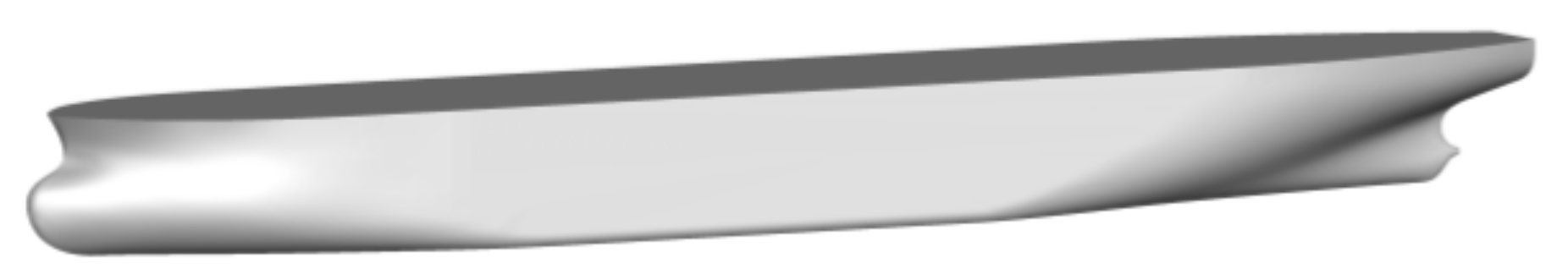
3.1. Ship Model and Computational Cases

In this study, the RANS computations are carried out for the naked hull of oil tanker KVLCC2 without propeller and rudder. The principal particulars of the full scale KVLCC2 are listed in Table 2, T is the draft, K G is the height of center of gravity from keel, C B is the block coefficient. The KVLCC2 geometry is shown in Figure 7.
In the present consideration, the head wave is defined as a 0° incidence wave angle, and the following waves as 180°, as shown in Figure 8. The computational cases for head waves and oblique waves are listed in Table 3. The experimental data from Seoul National University (SNU), Osaka University (OU), and European project SHOPERA are used to validate the present RANS results. The test conditions are also listed in Table 3.
For head wave cases, to ensure numerical stability, the calm-water resistance is calculated at first. The calm-water computation lasts for 100 s, to obtain the convergence resistance. Afterwards, the wave generation then starts. For each case, more than 20 encounter periods are performed during the computation.

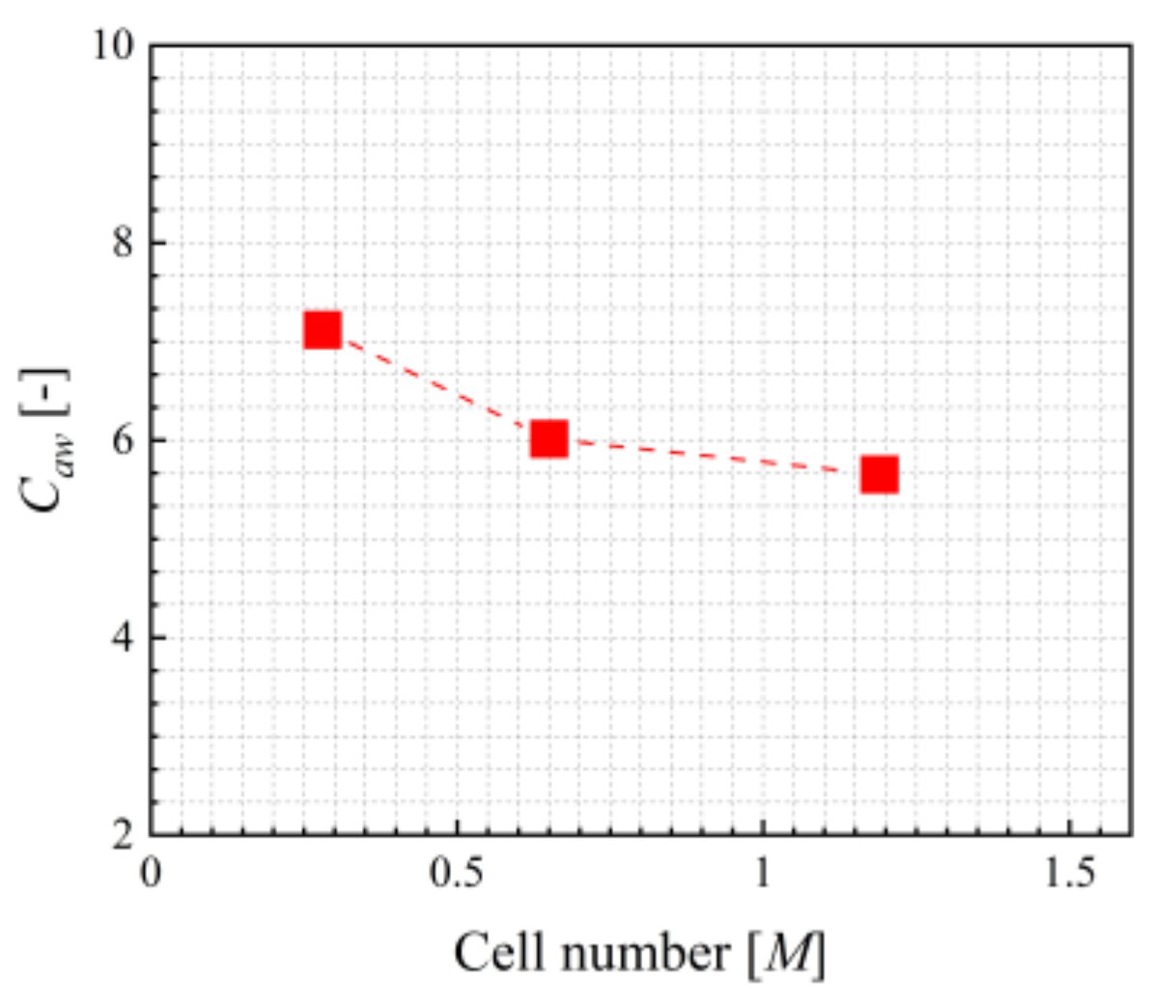
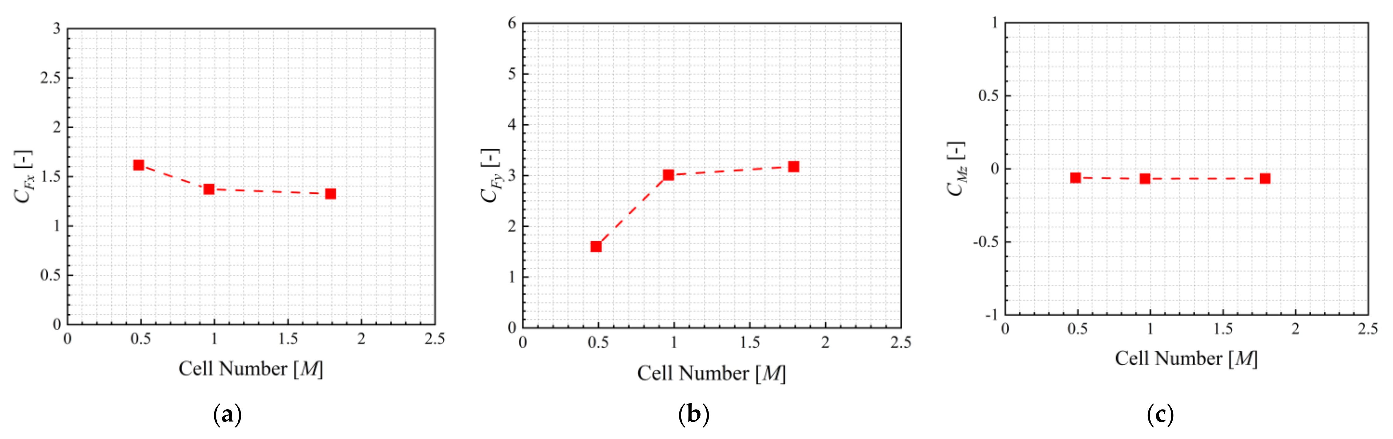
3.2. Grid Dependency Analysis

Grid dependency analysis is carried out at first. For the case of head waves, coarse, medium and fine grids with around 0.29, 0.65 and 1.19 million cells are systematically generated. According to the check of wave quality (see Section 2.5), for the medium grid there are around 72 cells in the wavelength direction and eight cells in wave height direction. The computation is performed for λ / L p p = 1.0, A / L p p = 0.005, and the ship model is 3.2 m long. The computed results for the head wave case are shown in Figure 9. As seen, the added resistance becomes closer as increasing the grid resolution. The added resistance is computed by subtracting the calm-water resistance from the mean resistance in head waves. The calm-water resistances, which are computed by the coarse, medium, and fine grids are about 4.308 N, 4.067 N, and 3.940 N, respectively. Compared with the SNU experimental data 3.966 N, the computational errors of calm-water resistance are about 8.62%, 2.54%, and 0.66% respectively. The discrepancy between the added resistances based on medium and fine grids is around 5.50%.
The grid dependency analysis is also carried out for oblique wave cases. Coarse, medium and fine grids are also systematically generated. There are around 0.48, 0.96 and 1.80 million cells, respectively. Similarly, there are around 72 cells in the wavelength direction and eight cells in the wave height direction for the medium grid. Here, wavelength is λ / L p p = 0.635 , wave amplitude is A / L p p = 0.007 , and wave incidence angle is 30°. For the oblique wave cases, the ship model is 4 m long. In addition, the ship speed is zero for oblique wave cases, as mentioned. The computed steady surge force, sway force and yaw moment are presented in Figure 10. In these figures, the dimensionless steady surge force, sway force, and yaw moment show convergence tendency with the increase of cell numbers, as expected.
Based on the above grid dependency analysis, both the medium grids for the head wave case and the oblique wave case seem to be of enough resolution, and they are then used for other computations.

3.3. Results and Analysis

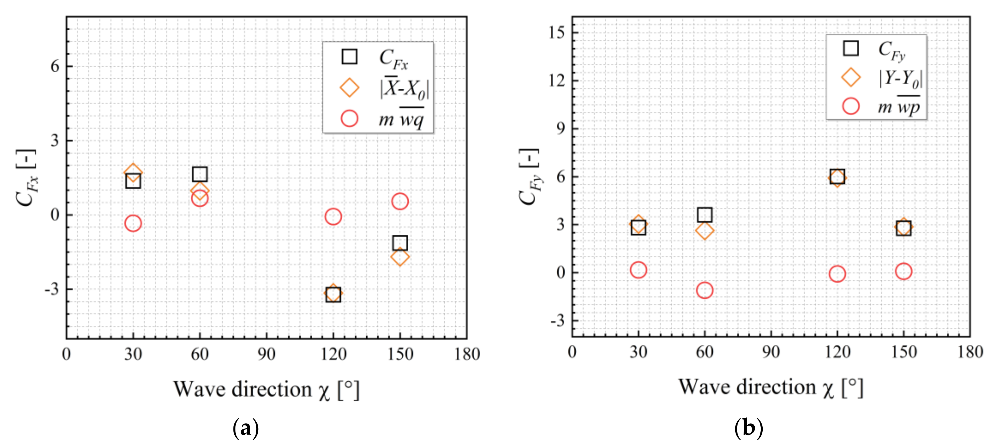
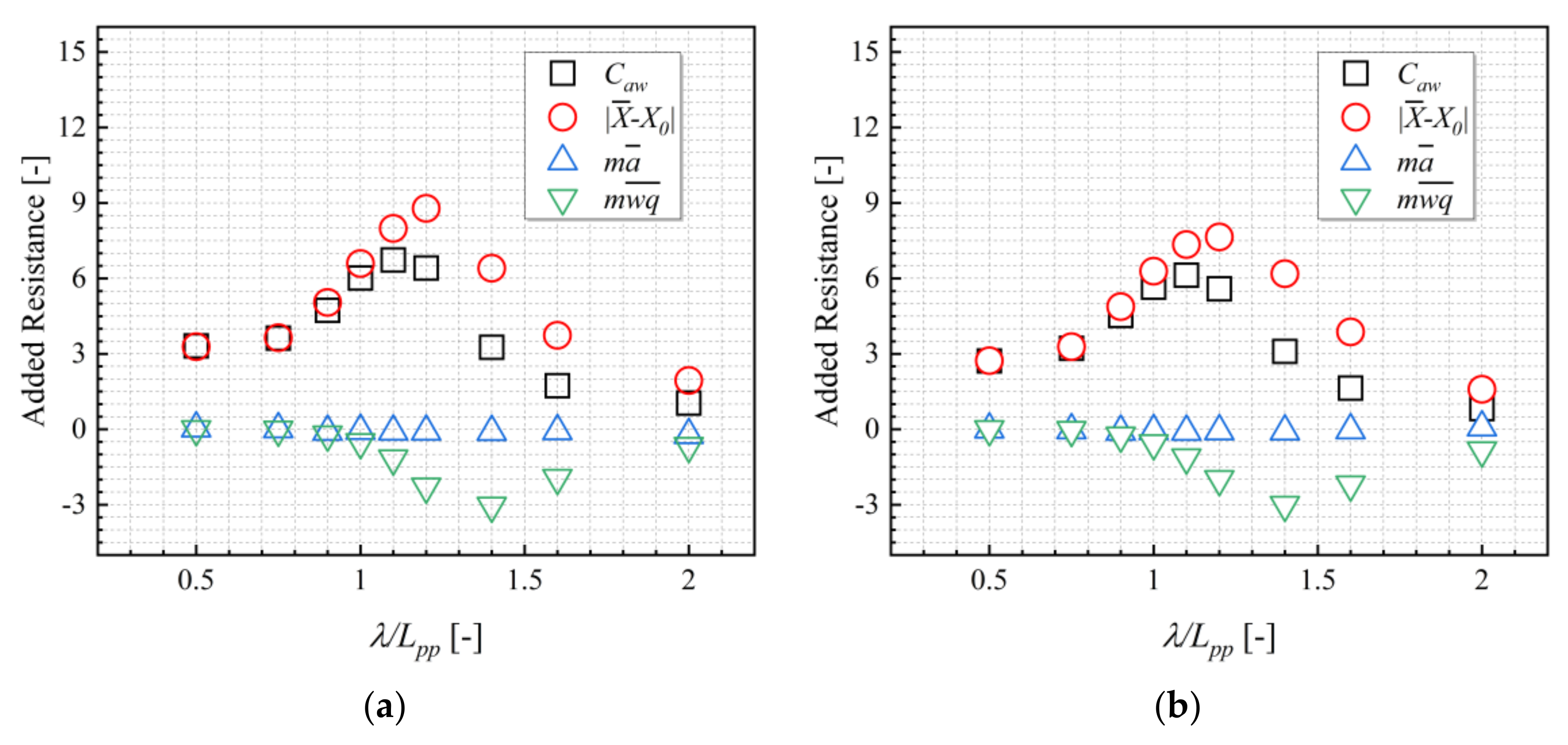
3.3.1. Component Analysis

The head wave cases are computed for nine wave lengths, which are λ / L p p = 0.5, 0.75, 0.9, 1.0, 1.1, 1.2, 1.4, 1.6 and 2.0, and considering two amplitudes A / L p p = 0.005 and 0.009375, where L p p = 3.2 m. Figure 11 shows the added resistance in head waves. The mean inertial force generated by longitudinal acceleration is almost zero, and it can be ignored in most cases. However, the mean inertia force generated by the coupling of heave and pitch have a significant contribution, especially in long waves. The comparison conforms the inertia effects of wave-induced ship motions to added resistance.
The computations in oblique waves are performed for λ / L p p = 0.635 and A / L p p = 0.007, where L p p = 4 m. The components of steady wave forces in oblique waves are shown in Figure 12. In oblique wave cases, the ship forward speed equals zero. The inertial effect has small contributions to the steady forces and moment, mainly because pitch, heave and roll are of very small amplitudes.

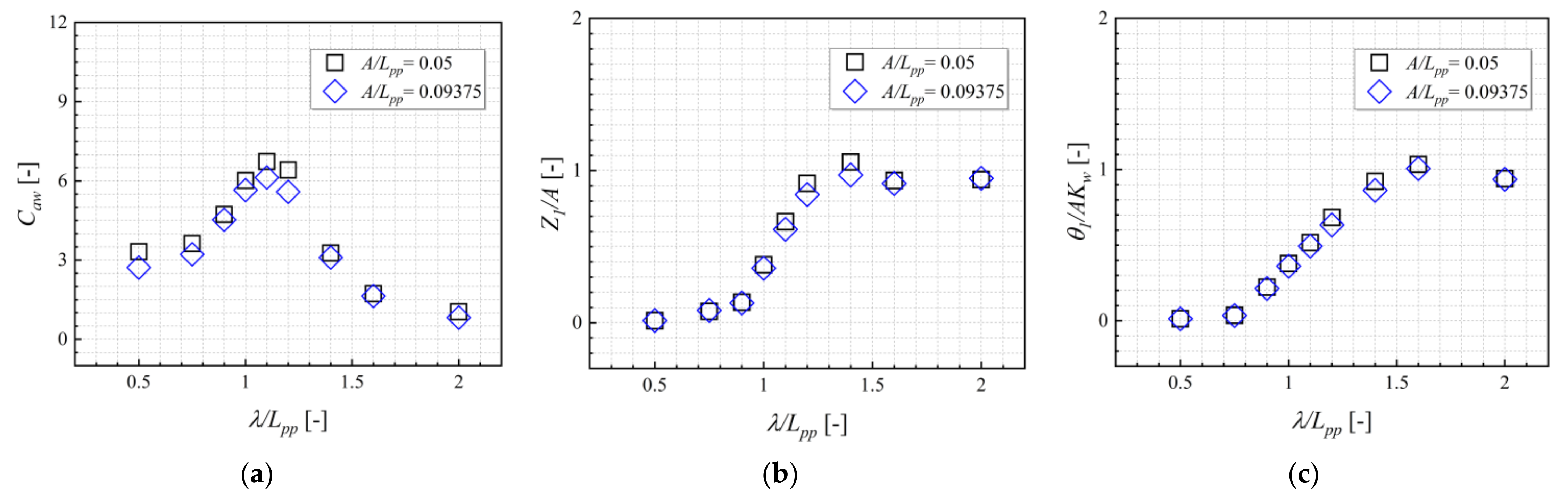
3.3.2. Effect of Wave Amplitude on Added Resistance

The results of added resistance, heave, and pitch RAOs at different wave amplitudes are compared in Figure 13. As seen in Figure 14a, for the two wave amplitudes, the computed curves of dimensionless added resistances versus wavelength do not coincide, meaning the added resistance is not proportional to the square of the wave amplitude. With decreasing wave amplitude, the dimensionless added resistances become large, in particular at λ / L p p = 1.1 and 1.2. In addition, it is also seen from Figure 13b,c that wave amplitude has quite a small influence on the heave and pitch RAOs.

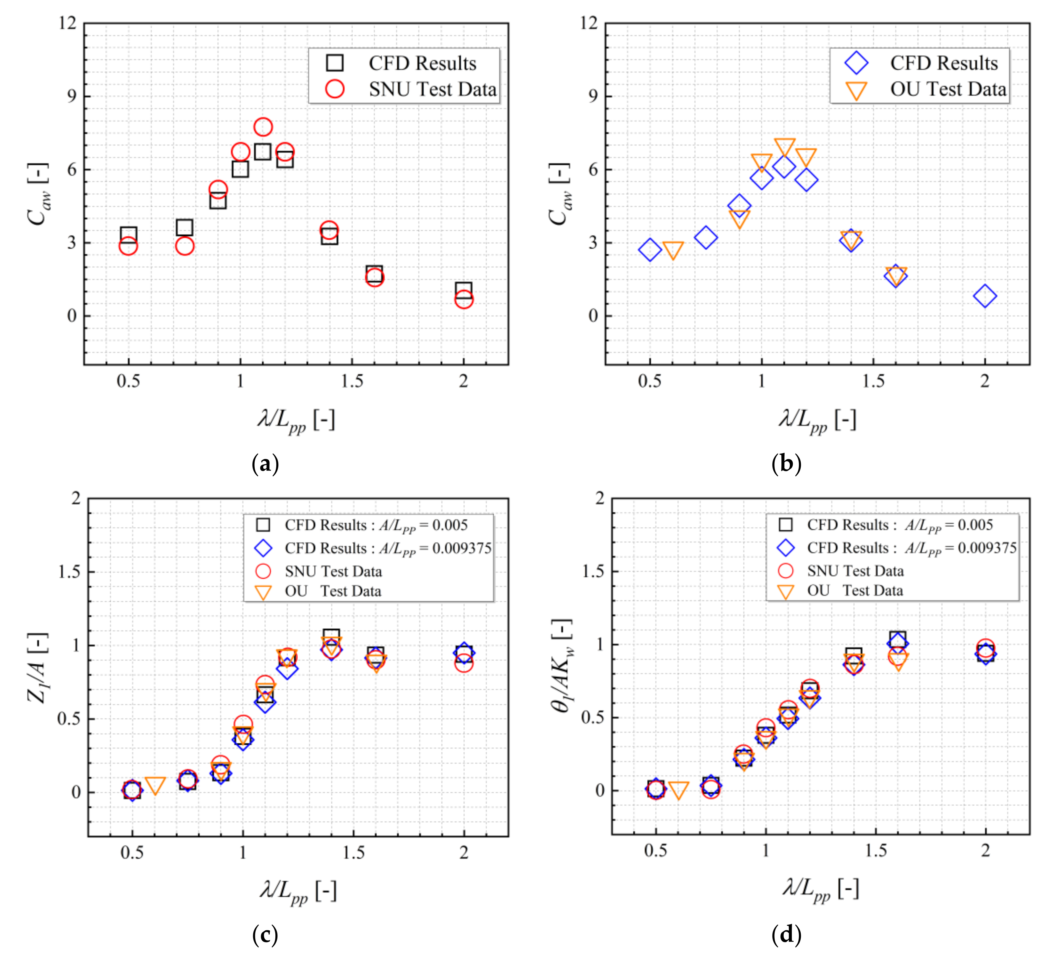
3.3.3. Validation of RANS Results

The accuracy of RANS results is validated by comparing them with the experimental data. In Figure 14, the added resistance with inertial effects, heave and pitch RAOs in head waves are compared with the experimental data. It can be observed that the RANS results are in good agreement with the experimental data.
The RANS results in oblique waves are compared with experimental data in Figure 15. For different incidence wave angles, the computed steady wave surge forces, sway forces and yaw moments show acceptable agreements with experimental data. The error for the sway force at an incident angle of 60° is large. The reason is as-yet unknown. The yaw moments are of very small values in the oblique waves as the ship is zero speed.
The wave snapshots and pressure distribution on the hull surface for a head wave case in an encounter period are shown in Figure 16. It can be observed that the pressure near the bow region changes considerably as the waves propagate from front to back. Green water on the bow deck at t = 0.75   T e is observed.
The wave snapshots and pressure distribution on the hull surface on the starboard side for four oblique angles are presented in Figure 17.

4. Conclusions

In this study, the wave-induced ship motions and steady wave force and moment for KVLCC2 are numerically predicted by using the RANS solver on OpenFOAM. New modules of wave boundary conditions are programed into OpenFOAM. The conclusions may be as follows:
(1)
The computed added resistance, as well as the steady wave sway force and yaw moment with inertia effects due to the wave-induced motions agrees well with the available experimental data. This confirms the contributions of the inertia effects. The inertia forces cannot be neglected if wave-induced motions are of large amplitudes.
(2)
The comparison of the computed resistances using two wave amplitudes indicates that added resistance is not proportional to the square of wave amplitude.
(3)
General good agreements between the computed results and the experimental data are observed. This shows that the RANS solver can be used as a tool for ship seakeeping analysis.
Great efforts in future works will be devoted to the cases, considering a full appended ship (propeller and rudder), and will also concern the ship hydrodynamic performances in irregular waves.

Author Contributions

Conceptualization, J.Y.; Data curation, Q.G. and J.Y.; Formal analysis, J.Y.; Funding acquisition, L.S.; Investigation, Q.G. and J.Y.; Methodology, Q.G. and J.Y.; Project administration, J.Y. and L.S.; Resources, Q.G.; Software, Q.G. and J.Y.; Supervision, J.Y.; Validation, Q.G. and J.Y.; Visualization, Q.G. and J.Y.; Writing—original draft, Q.G.; Writing—review & editing, J.Y. All authors have read and agreed to the published version of the manuscript.

Funding

This research was funded by the National Natural Science Foundation of China, grant numbers 51809203, 51720105011, 51609188.

Institutional Review Board Statement

Not applicable.

Informed Consent Statement

Not applicable.

Data Availability Statement

The data used to support the findings of this study are available from the corresponding author upon request.

Conflicts of Interest

The authors declare no conflict of interest.

References

  1. International Maritime Organization. Interim Guidelines for the Calculation of the Coefficient fw for Decrease in Ship Speed in a Representative Sea Condition for Trial Use; IMO: London, UK, 2012. [Google Scholar]
  2. Specialist Committee on Seakeeping. Final Report and Recommendations to the 27th ITTC. In Proceedings of the the 27th International Towing Tank Conference, Copenhagen, Denmark, 31 August–5 September 2014. [Google Scholar]
  3. International Maritime Organization. Interim Guidelines for Determining Minimum Propulsion Power to Maintain the Maneuverability in Adverse Conditions; IMO: London, UK, 2013. [Google Scholar]
  4. Sadat-Hosseini, H.; Wu, P.-C.; Carrica, P.M.; Kim, H.; Toda, Y.; Stern, F. CFD verification and validation of added resistance and motions of KVLCC2 with fixed and free surge in short and long head waves. Ocean Eng. 2013, 59, 240–273. [Google Scholar] [CrossRef]
  5. Lee, J.; Park, D.-M.; Kim, Y. Experimental investigation on the added resistance of modified KVLCC2 hull forms with different bow shapes. Proc. Inst. Mech. Eng. Part M J. Eng. Marit. Environ. 2017, 231, 395–410. [Google Scholar] [CrossRef]
  6. Shigunov, V.; Moctar, O.E.; Papanikolaou, A.; Potthoff, R.; Liu, S. International benchmark study on numerical simulation methods for prediction of manoeuvrability of ships in waves. Ocean Eng. 2018, 165, 365–385. [Google Scholar] [CrossRef]
  7. Havelock, T.H. The resistance of a ship among waves. Proc. R. Soc. Lond. Ser. A Math. Phys. Sci. 1937, 161, 299–308. [Google Scholar]
  8. Salvesen, N. Second-order steady state forces and moments on surface ships in oblique regular waves. In Proceedings of the International Symposium on the Dynamics of Marine Vehicles and Structures in Waves; Naval Ship Research and Development Center: Washington, DC, USA, 1974. [Google Scholar]
  9. Faltinsen, O.M.; Minsaas, K.J.; Liapis, N.; Skjørdal, S.O. Prediction of resistance and propulsion of a ship in a seaway. In Proceedings of the 13th Symposium on Naval Hydrodynamics, Tokyo, Japan, 6–8 October 1980; pp. 505–529. [Google Scholar]
  10. Kim, K.H.; Kim, Y. Numerical study on added resistance of ships by using a time-domain Rankine panel method. Ocean Eng. 2011, 38, 1357–1367. [Google Scholar] [CrossRef]
  11. Maruo, H. The drift of a body floating on waves. J. Ship Res. 1960, 4, 1–10. [Google Scholar]
  12. Joosen, W. Added resistance of ships in waves. In Proceedings of the 6th Symposium on Naval Hydrodynamics; National Academy Press: Washington, DC, USA, 1966. [Google Scholar]
  13. Newman, J.N. The drift force and moment on ships in waves. J. Ship Res. 1967, 11, 51–60. [Google Scholar] [CrossRef]
  14. Gerritsma, J.; Beukelman, W. Analysis of the resistance increase in waves of a fast cargo ship. Int. Shipbuild. Progress 1972, 19, 285–293. [Google Scholar] [CrossRef]
  15. Chizhiumov, S.D. Numerical Modeling of Ship Motion in Heavy Sea Conditions. In Proceedings of the Sixth ISOPE Pacific/Asia Offshore Mechanics Symposium, Vladivostok, Russia, 12–16 September 2004. [Google Scholar]
  16. Kim, B.Y.; Seo, M.G.; Park, D.M.; Yang, K.K. Numerical and Experimental Analyses of Added Resistance in Waves. In Proceedings of the 29th International Workshop on Water Waves and Floating Bodies, Osaka, Japan, 30 March–2 April 2014. [Google Scholar]
  17. Park, D.-M.; Kim, Y.; Seo, M.-G.; Lee, J. Study on added resistance of a tanker in head waves at different drafts. Ocean Eng. 2016, 111, 569–581. [Google Scholar] [CrossRef] [Green Version]
  18. Yasukawa, H.; Matsumoto, A.; Ikezoe, S. Wave Height Effect on Added Resistance of Full Hull Ships in Waves. J. Jpn. Soc. Nav. Archit. Ocean Eng. 2016, 23, 45–54. [Google Scholar]
  19. Lee, J.-H.; Kim, Y. Study on added resistance of a ship under parametric roll motion. Ocean Eng. 2017, 144, 1–13. [Google Scholar] [CrossRef]
  20. Yu, J.W.; Lee, C.M.; Choi, J.E.; Lee, I. Effect of ship motions on added resistance in regular head waves of KVLCC2. Ocean Eng. 2017, 146, 375–387. [Google Scholar] [CrossRef]
  21. Guo, B.; Steen, S.; Deng, G. Seakeeping prediction of KVLCC2 in head waves with RANS. Appl. Ocean Res. 2012, 35, 56–67. [Google Scholar] [CrossRef]
  22. Wu, C.; Yan, D.; Qiu, G.; Ni, Y. CFD Computation of Added Resistance for KVLCC2 Model in Head Short Waves. J. Ship Mech. 2015, 19, 229–236. [Google Scholar]
  23. Kim, M.; Hizir, O.; Turan, O.; Incecik, A. Estimation of added resistance and ship speed loss in a seaway. Ocean Eng. 2017, 141, 465–476. [Google Scholar] [CrossRef] [Green Version]
  24. Sigmund, S.; Moctar, O.E. Numerical and experimental investigation of added resistance of different ship types in short and long waves. Ocean Eng. 2018, 147, 51–67. [Google Scholar] [CrossRef]
  25. Uharek, S.; Cura-Hochbaum, A. The influence of inertial effects on the mean forces and moments on a ship sailing in oblique waves part b: Numerical prediction using a rans code. Ocean Eng. 2018, 165, 264–276. [Google Scholar] [CrossRef]
  26. Lee, C.M.; Park, S.C.; Yu, J.W.; Choi, J.E.; Lee, I. Effects of diffraction in regular head waves on added resistance and wake using cfd. Int. J. Nav. Arch. Ocean Eng. 2019, 11, 736–749. [Google Scholar] [CrossRef]
  27. Islam, H.; Guedes Soares, C. Uncertainty analysis in ship resistance prediction using OpenFOAM. Ocean Eng. 2019, 191, 105805. [Google Scholar] [CrossRef]
  28. Yao, J.; Su, Y.; Song, X.; Liu, Z.; Cheng, X.; Zhan, C. RANS Analysis of the Motions and Added Resistance for KVLCC2 in Head Regular Waves. Appl. Ocean Res. 2020, 105, 102398. [Google Scholar] [CrossRef]
  29. Islam, H.; Guedes Soares, C.; Liu, J.; Wang, X. Propulsion power prediction for an inland container vessel in open and restricted channel from model and full-scale simulations. Ocean Eng. 2021, 229, 108621. [Google Scholar] [CrossRef]
  30. Jiao, J.; Huang, S.; Wang, S.; Guedes Soares, C. A CFD–FEA two-way coupling method for predicting ship wave loads and hydroelastic responses. Appl. Ocean Res. 2021, 117, 102919. [Google Scholar] [CrossRef]
  31. Yao, J.; Cheng, X.; Song, X.; Zhan, C.; Liu, Z. RANS Computation of the Mean Forces and Moments, and Wave-Induced Six Degrees of Freedom Motions for a Ship Moving Obliquely in Regular Head and Beam Waves. J. Mar. Sci. Eng. 2021, 9, 1176. [Google Scholar] [CrossRef]
  32. Borkowski, P. Numerical Modeling of Wave Disturbances in the Process of Ship Movement Control. Algorithms 2018, 11, 130. [Google Scholar] [CrossRef] [Green Version]
  33. Jacobsen, N.G.; Fuhrman, D.R.; Fredsone, J. A wave generation toolbox for the open-source CFD library: Openfoam. Int. J. Numer. Methods Fluids 2012, 70, 1073–1088. [Google Scholar] [CrossRef]
Figure 1. Coordinate system.
Jmse 09 01459 g001
Figure 2. Computational domain, boundary conditions, and grid arrangement for head wave cases. (a) Computational domain and boundary condition; (b) Grid arrangement.
Jmse 09 01459 g002
Figure 3. Computational domain, boundary conditions, and grid arrangement for oblique wave cases. (a) Computational domain and boundary condition; (b) Grid arrangement.
Jmse 09 01459 g003
Figure 4. The sketch of wave absorbing zone.
Jmse 09 01459 g004
Figure 5. Influence of grid size on wave quality.
Jmse 09 01459 g005
Figure 6. Influence of time step on wave quality.
Jmse 09 01459 g006
Figure 7. Geometry of the KVLCC2.
Jmse 09 01459 g007
Figure 8. The sketch of wave incident angle.
Jmse 09 01459 g008
Figure 9. Grid dependency analysis for head waves.
Jmse 09 01459 g009
Figure 10. Grid dependency analysis for oblique waves. (a) Steady surge force; (b) Steady sway force; (c) Steady yaw moment.
Jmse 09 01459 g010
Figure 11. Components of added resistance in head waves. (a) A / L p p = 0 . 005 ; (b) A / L p p = 0 . 009375 .
Jmse 09 01459 g011
Figure 12. Components of steady surge force and sway force in oblique waves. (a) Steady surge force; (b) Steady sway force.
Jmse 09 01459 g012
Figure 13. The influence of wave amplitudes. (a) Added resistance; (b) Heave RAOs; (c) Pitch RAOs.
Jmse 09 01459 g013
Figure 14. Compare the CFD results with the experiment data for head wave cases. (a) A / L p p = 0 . 005 ; (b) A / L p p = 0 . 009375 ; (c) Heave RAOs; (d) Pitch RAOs.
Jmse 09 01459 g014
Figure 15. Compare the CFD results with the experiment data for oblique wave cases. (a) Steady surge force; (b) Steady sway force; (c) Steady yaw moment.
Jmse 09 01459 g015
Figure 16. Wave snapshots and hull surface pressure in an encounter period. (a) t = 0 ; (b) t = 0.25   T e ; (c) t = 0.5   T e ; (d) t = 0.75   T e .
Jmse 09 01459 g016
Figure 17. Wave snapshots and hull surface pressure of four incidence angels. (a) χ = 30 ° ; (b) χ = 60 ° ; (c) χ = 120 ° ; (d) χ = 150 ° .
Jmse 09 01459 g017
Table 1. Cases for the check of wave quality.
Cases Cell Numbers in a
Wavelength
Cell Numbers in a
Wave Height
Time Step [s]
C013680.001
C027240.001
C037280.001
C0472160.001
C0514480.001
C067280.004
C077280.002
C087280.0005
Table 2. Principal particulars of KVLCC2.
ItemsReal Ship
Scale1
L p p [m]320
B [m]58
T [m]20.8
K G [m]18.6
C B [-]0.81
Table 3. Experimental and CFD cases.
Items EFD CFD
SNUOUSHOPERA
Scale1001008080, 100
χ [°]0030~1300~150
F r 0.1420.14200, 0.142
λ / L p p 0.3~20.6~20.2~1.20.5~2
A / L p p 0.0050.0093750.0070.005, 0.007, 0.009375
Publisher’s Note: MDPI stays neutral with regard to jurisdictional claims in published maps and institutional affiliations.

