Article

HESS in a Wind Turbine Generator: Assessment of Electric Performances at Point of Common Coupling with the Grid

by
Linda Barelli
1,
Dario Pelosi
1,
Dana Alexandra Ciupageanu
1,2,
Panfilo Andrea Ottaviano
1,
Michela Longo
3,* and
Dario Zaninelli
3
1
Department of Engineering, University of Perugia, Via G. Duranti 93, 06125 Perugia, Italy
2
Engineering Faculty, University Politehnica of Bucharest, Splaiul Independentei 313, 060042 Bucharest, Romania
3
Department of Energy, Politecnico di Milano, Via La Masa 34, 20156 Milano, Italy
*
Author to whom correspondence should be addressed.
J. Mar. Sci. Eng. 2021, 9(12), 1413; https://doi.org/10.3390/jmse9121413
Submission received: 12 November 2021 / Revised: 29 November 2021 / Accepted: 1 December 2021 / Published: 10 December 2021
(This article belongs to the Section Marine Energy)

Abstract

:
Among Renewable Energy Sources (RES), wind energy is emerging as one of the largest installed renewable-power-generating capacities. The technological maturity of wind turbines, together with the large marine wind resource, is currently boosting the development of offshore wind turbines, which can reduce the visual and noise impacts and produce more power due to higher wind speeds. Nevertheless, the increasing penetration of wind energy, as well as other renewable sources, is still a great concern due to their fluctuating and intermittent behavior. Therefore, in order to cover the mismatch between power generation and load demand, the stochastic nature of renewables has to be mitigated. Among proposed solutions, the integration of energy storage systems in wind power plants is one of the most effective. In this paper, a Hybrid Energy Storage System (HESS) is integrated into an offshore wind turbine generator with the aim of demonstrating the benefits in terms of fluctuation reduction of the active power and voltage waveform frequency, specifically at the Point of Common Coupling (PCC). A MATLAB®/SimPowerSystems model composed of an offshore wind turbine interfaced with the grid through a full-scale back-to-back converter and a flywheel-battery-based HESS connected to the converter DC-link has been developed and compared with the case of storage absence. Simulations were carried out in reference to the wind turbine’s stress conditions and were selected—according to our previous work—in terms of the wind power step. Specifically, the main outcomes of this paper show that HESS integration allows for a reduction in the active power variation, when the wind power step is applied, to about 3% and 4.8%, respectively, for the simulated scenarios, in relation to more than 30% and 42% obtained for the no-storage case. Furthermore, HESS is able to reduce the transient time of the frequency of the three-phase voltage waveform at the PCC by more than 89% for both the investigated cases. Hence, this research demonstrates how HESS, coupled with renewable power plants, can strongly enhance grid safety and stability issues in order to meet the stringent requirements relating to the massive RES penetration expected in the coming years.

1. Introduction

Today, power systems worldwide are facing multiple challenges related to the progressive integration of Renewable Energy Sources (RES) in response to climate change mitigation policies [1]. RES’s intermittency and unpredictable behavior raise many issues in terms of operation and control of energy systems with high shares of renewable power [2]. Compensating measures are therefore required to cope with the RES’s uncertainty while maximizing their integration benefits [3]. Moreover, RES power plants are required to meet several conditions in terms of power quality at the point of common coupling (PCC), reliability of control and stability implications. These conditions emerge from several regulations that have recently been developed and enforced to support RES penetration while minimizing the negative effects on the distribution and transmission of electrical infrastructure [4]. Thus, grid codes have been updated in order to accommodate high-RES shares and maintain the frequency and voltage within acceptable limits [5]. Indeed, several papers have proposed robust methods in order to optimize the frequency control of interconnected power systems [6,7,8].
Among RES, wind power is emerging as one of the largest installed RES-generating capacities, reaching 733 GW in 2020, which represents 26% of the total RES capacity worldwide (hydro energy accounts for 46% while PV gathers 25% of the total RES capacity) [9]. Wind Energy Conversion (WEC) systems are suitable for both large-scale and small-scale applications, making them of great interest for interconnected or remote topologies. The increasing penetration of WECs has also led to the development of offshore wind turbines, since marine wind is available all over the world and is greater than land-based wind energy [10]. Additional advantages of the offshore WEC configuration concern the lower acoustic and visual impact and higher laminar wind intensity at greater heights and a higher number of equivalent operating hours. Nevertheless, the construction, assembly and maintenance have proven very complex to date. Considering the framework of offshore wind turbines, machines such as the Doubly-Fed Induction Generator (DFIG) and Permanent Magnet Synchronous Generator (PMSG) are the most suitable technologies thanks to their high efficiency and capacity to operate at variable speeds [11]. In particular, PMSG is a good option due to its self-excitation property, allowing operation at a high power factor and efficiency. Moreover, the salient pole of PMSG operates at low speeds; hence, the gearbox can be removed, thereby reducing the system costs.
Therefore, investigating WEC systems and their integration perspectives represents an important topic of discussion, and further research into each stage of WEC development is required. For instance, as spatial characteristics strongly influence the output of a wind farm, its design is subject to optimization. A study regarding the optimal design of a wind farm electrical interface is proposed in [12], wherein a methodology based on a genetic algorithm is introduced. Another aspect related to the electrical interactions between WEC and the embedding network is turbine control, which is extensively addressed in the literature [13]. The impact of WEC integration in power systems is addressed in [14,15,16], proving the need to implement mitigation measures to reduce curtailment and increase systems’ flexibility [17].
Energy Storage Systems (ESS) can contribute to meeting the power requirements in both steady and dynamic operating conditions. In particular, storage devices with high power density characteristics are suitable for coping with high-frequency transients, while high energy storage technologies are fitted for short/medium steady-state exploitation. ESSs fulfill a very important role in the stabilization of the electrical network, taking into account increasing RES penetration [18]. ESSs, which have reached commercial maturity, as well as many innovative solutions, have been investigated in the literature, with extensive reviews being presented in [19,20,21].
Hybrid Energy Storage Systems (HESSs), comprising (multiple) energy storage devices coupled to various RES plants, are increasingly widespread, providing the advantages of a clean and reliable energy supply while overcoming variability challenges [22]. The type of electrical interconnection selected for such systems is very important, and researchers must take into account several aspects, reflecting on the reliability of the resulting system [23]. DC configurations have recently become a matter of interest, as many RES and storage technologies (PV arrays, stationary and electric vehicles batteries) have a DC output. Results described in the literature show that DC architecture may also improve self-consumption by up to 6% [24]. However, AC interconnection configurations bring the benefits of lower costs, as they provide the possibility of employing already-available infrastructures at all levels (distribution, transmission, etc.). Moreover, the protection of AC systems is easier and less expensive, contributing to the overall cost reduction. The downsides of AC compared to the DC architectures include smaller scalability features and slightly inferior performances. In the end, comparing DC and AC electrical architectures for RES applications, it is highlighted that selecting one of them is a multi-criteria decision, with both providing particular advantages [23,24,25]. However, to the best of our knowledge, no comparative analysis of the electrical performances of a system composed by an offshore WEC with and without HESS integration has been carried out to assess the power quality impact at the PCC. Therefore, in order to fill this gap, the purpose of the present research is to:
(i)
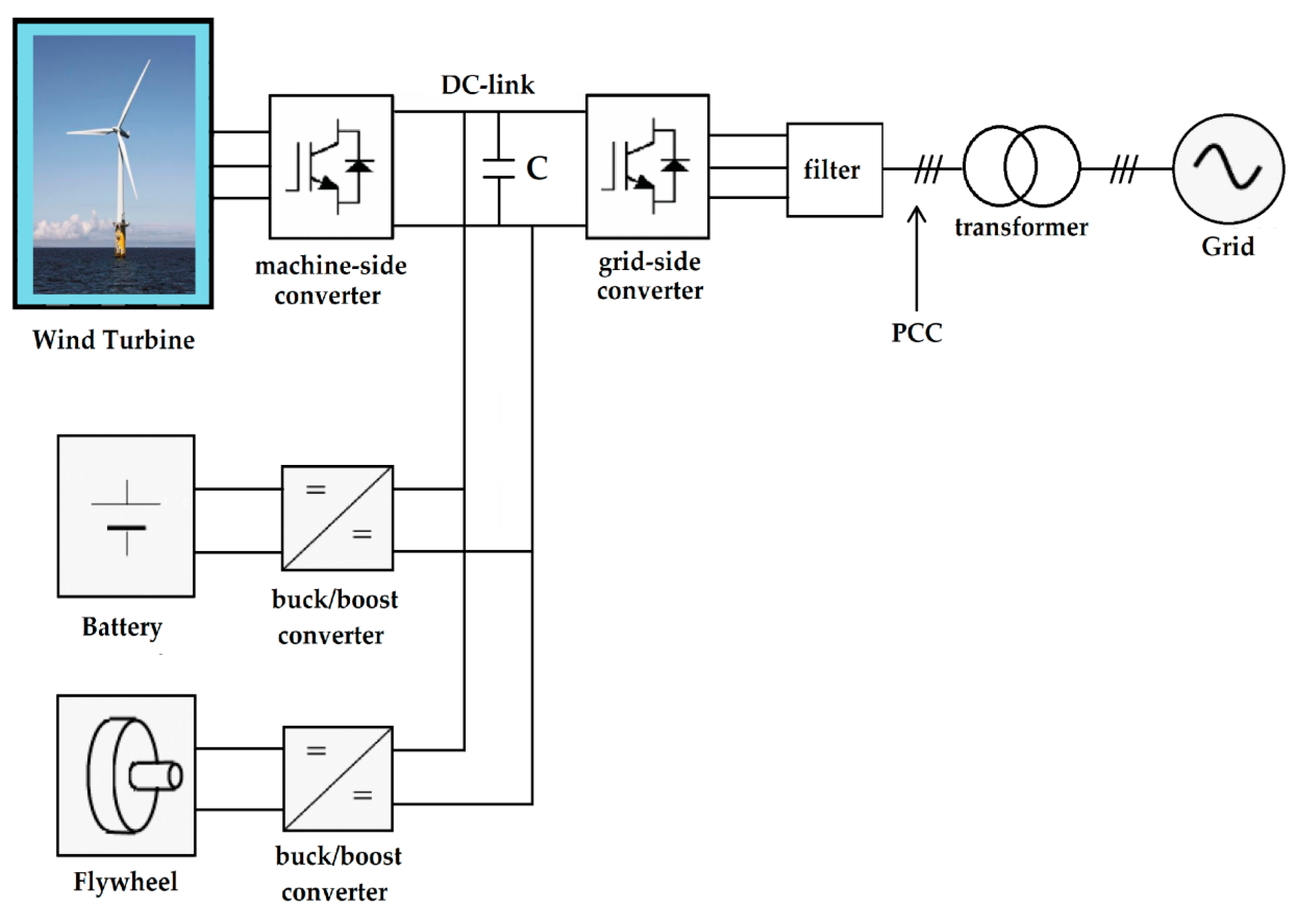
Investigate the electric performances at the PCC of a Li-ion battery/flywheel HESS coupling to an offshore WEC, which is interfaced with the grid by means of a full-scale back-to-back converter;
(ii)
Confirm the effectiveness of the Simultaneous Perturbation Stochastic Approximation (SPSA) power management strategy for smoothing the wind power generation;
(iii)
Compare the behavior of the offshore WEC in the presence/absence of the HESS in terms of transient time and amplitude of the voltage waveform frequency at the PCC under severe wind turbine operating conditions in terms of the produced power ramp.
Specifically, a 2 MW wind turbine driving a Permanent Magnet Synchronous Generator (PMSG) coupled to a battery/flywheel HESS is considered. An electric model is developed in MATLAB®/SimPowerSystems with the aim of analyzing the dynamic behavior of the system in severe simulation conditions, selected based on the most stressful wind power ramp occurrences identified over measurements performed at a real installation. SimPowerSystems software is widely used for power quality analyses, as indicated in [26,27,28,29,30,31]. In order to assess the proposed configuration performances and demonstrate the benefits of HESS integration, the active power variation and voltage waveform frequency evolution at the PCC is evaluated during a step wind power variation. Comparative analyses between the cases of HESS inclusion and absence show that HESS integration allows a reduction in the transient time of the voltage waveform frequency at the PCC of up to 89.7% for the case relating to wind turbine power generation increase and up to 95.7% for the scenario of sudden power generation reduction. Moreover, the effectiveness of the SPSA power management strategy for smoothing the power profile towards both the grid and the battery is also confirmed, as already discussed in previous publications by the present authors [32,33].
This research is organized as follows: Section 2 describes the modeling of the main components of the investigated system in a MATLAB®/SimPowerSystems environment. Section 3 defines the simulation scenarios according to the most stressful grid conditions. Section 4 illustrates the most significant results obtained from simulations, comparing the case of the presence and absence of HESS in coupling to the wind turbine. The main conclusions of the work and future outlooks are presented in Section 5.

2. Model Description

The main system components implemented in the SimPowerSystems (SPS) environment are illustrated below. The system configuration is reported in Figure 1. The chosen electrical architecture topology consists of a Wind Turbine Generator (WTG) and a grid-tied full-scale back-to-back (B2B) converter, to which the DC-link (whose voltage is fixed at 1150 VDC) of the HESS is directly connected. The voltage grid is considered equal to the voltage output of the wind turbine (i.e., 690 VL-L), as is usually specified by WTG manufacturers for 50 Hz grids [34]. The overall system results in (i) a 2 MW wind turbine PMSG, (ii) a battery with a capacity of 200 kWh and 600/200 kW as maximum discharge/charge power, coupled with a flywheel of 275 kW rated power and 21 kWh capacity. The sizing procedure for the hybrid ESS is described in a previous publication [33] based on real wind. The grid is represented as a voltage source interconnected with the B2B converter through a transformer.

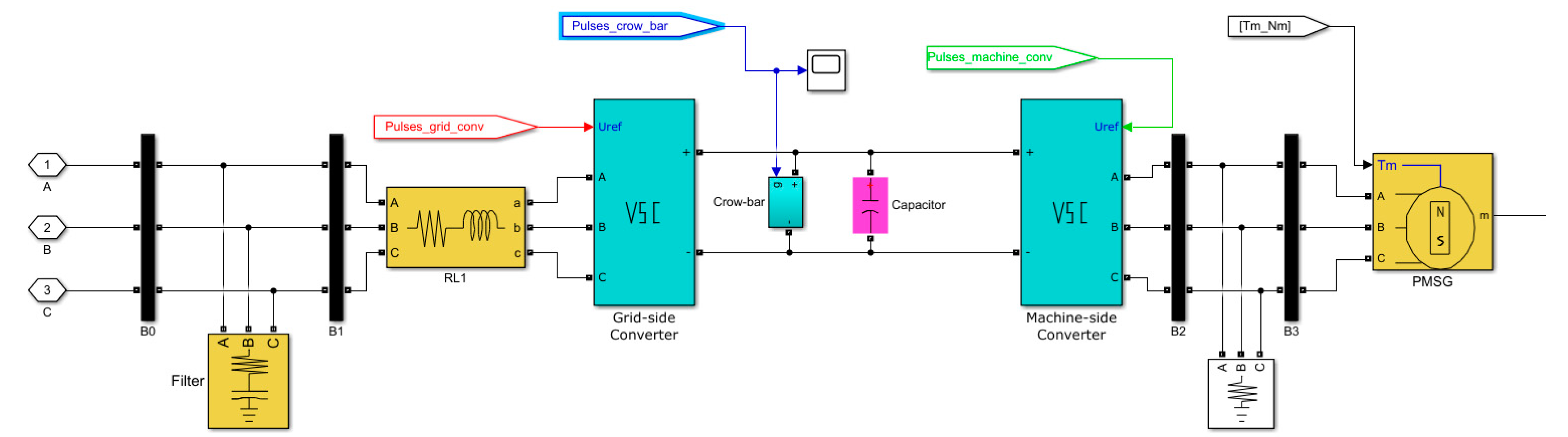
2.1. Wind Turbine Section
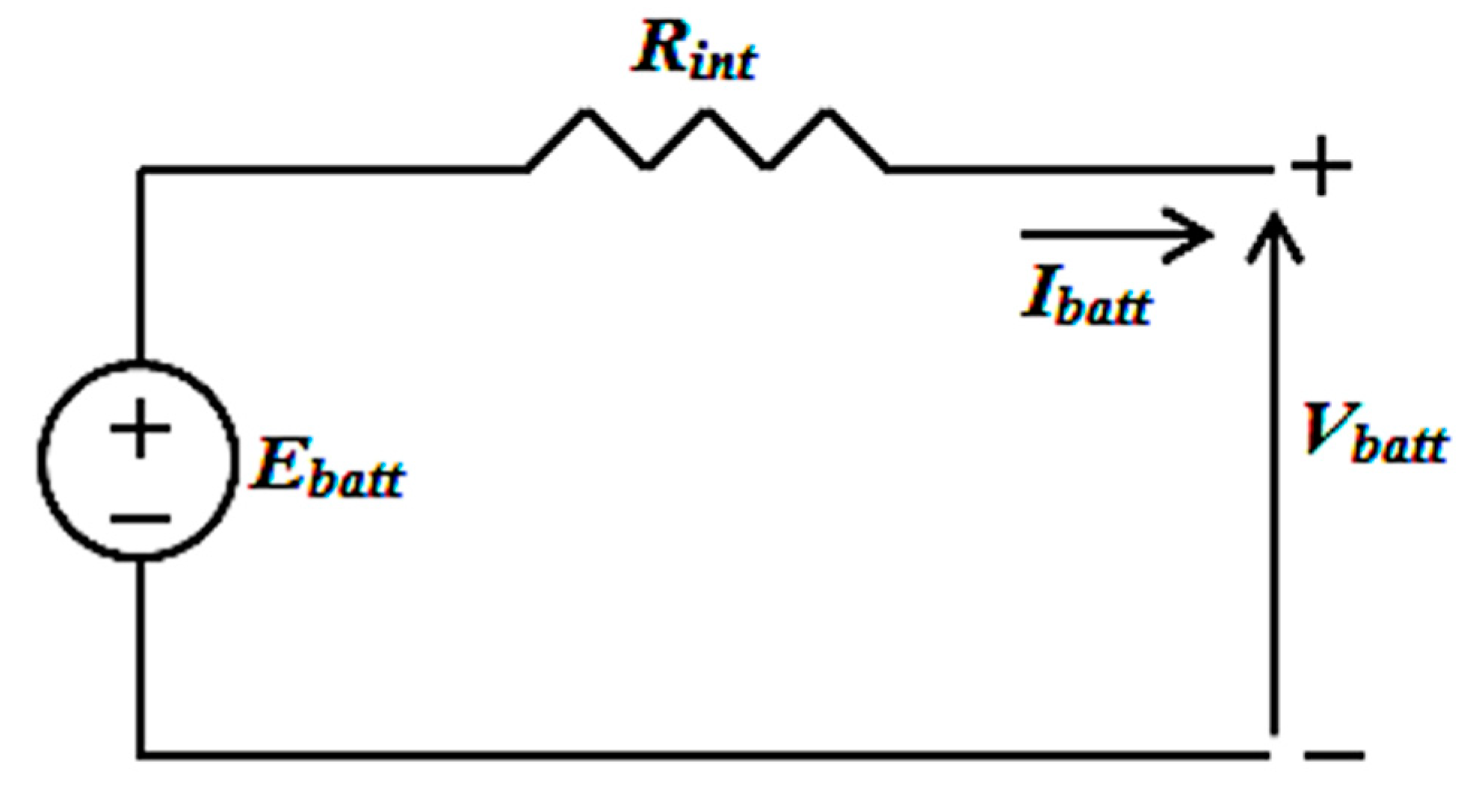
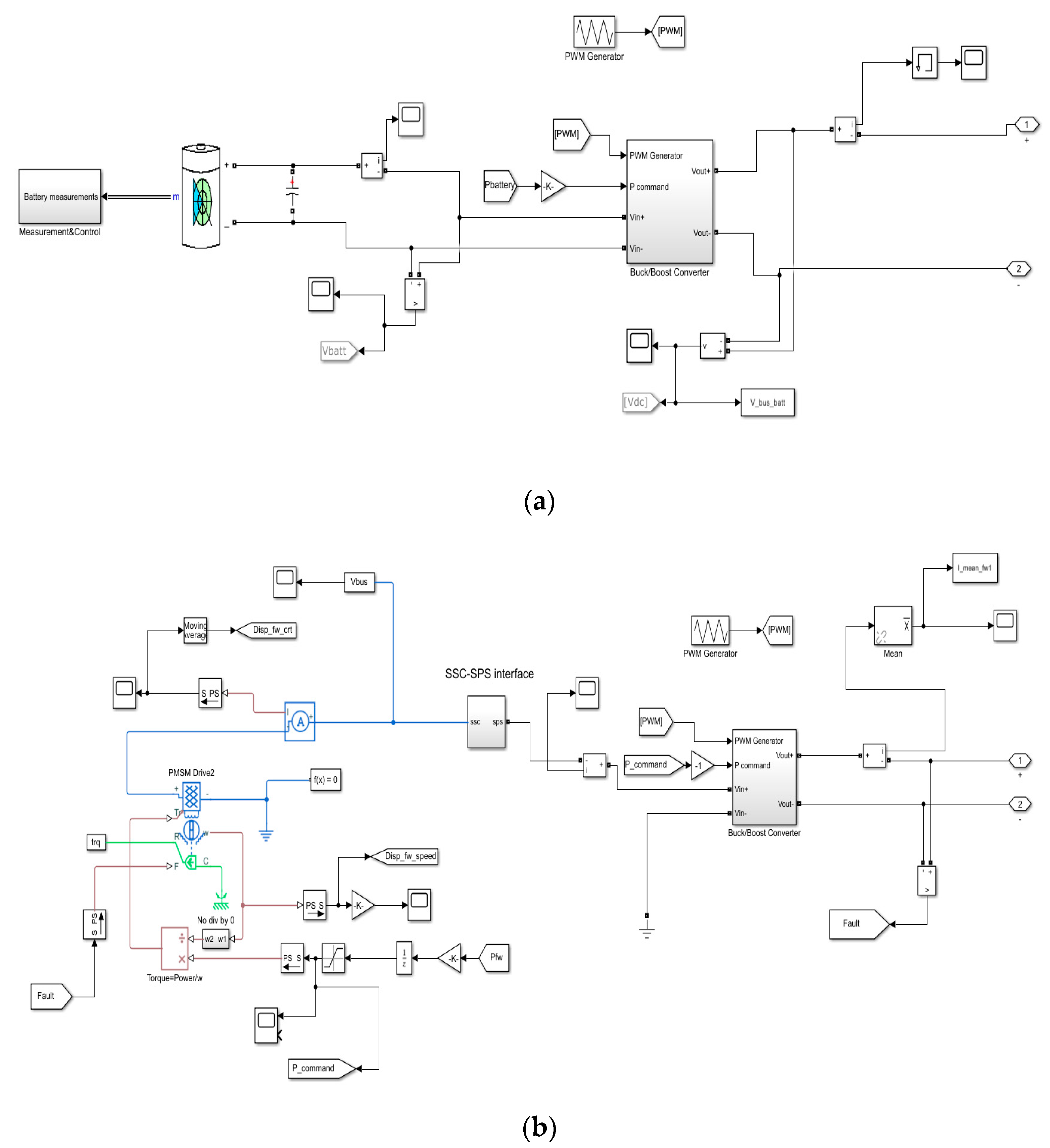
The implemented wind turbine generator is modeled as a Permanent Magnet Synchronous Generator (PMSG) connected to the grid by means of a B2B converter, according to [35]. Figure 2 depicts the wind turbine based on low-speed PMSG and the full-scale B2B converter consisting of a Grid-Side Converter (GSC) and a machine-side converter (MSC) connected through a DC-link. The MSC relates to the stator of PMSG, while the GSC relates to the grid. Both GSC and MSC are modeled as voltage source converters (VSCs). Such a converter allows the decoupling of the control of the machine with respect to the grid, maximizing the wind turbine power production rate without interfering with the grid frequency. The B2B converter is controlled by means of the pulse width modulation (PWM) strategy. The pitch angle control has not been considered in this work. Such electrical topology allows for larger flexibility with respect to the Doubly Fed Induction Generator (DFIG), making the control of real and reactive power more effective [36]. In order to avoid over-voltages of the DC-link that could damage the full-scale B2B converter, an active crowbar protection system is employed. Such protection consists of an Insulated Gate Bipolar Transistor (IGBT), which is controlled by means of a relay that is switched on when the voltage overcomes a certain threshold (i.e., 1500 V).
Concerning the electric generator for the investigated wind turbine, the PMSG technology represents one of the most promising machines for wind generation to date due to its self-excited nature, high efficiency and power factor [36]. Furthermore, the considered PMSG technology requires no gearbox system because of its low rotational speed, in line with the wind turbine rotor blades. Therefore, no careful and regular maintenance is required for this wind turbine topology, unlike the DFIG-based ones [37]. Therefore, the PMSG generator with a full-scale B2B converter currently represents one of the most attractive solutions [38]. Nevertheless, as major drawbacks, PMSG wind turbines require high capital costs and are very complex in terms of construction and control strategy.
The instantaneous torque of the PMSG has been calculated within the model moving from the wind speed profiles and according to the wind turbine power curve deduced from [39], as detailed in the next sections. Furthermore, the grid-side output filter is used to reduce the harmonic content of the voltage and current coming from GSC. Table 1 reports the main parameters used for the PMSG implementation in the SPS model.

2.2. HESS Section

A Li-ion battery is implemented using a generic dynamic block from the SimPowerSystems library. Equations (1) and (2), respectively, describe the charging and discharging process. Figure 3 shows the battery equivalent circuit.
f d i s c h ( C o u t , i * , i ) = E 0 K C m a x C m a x C o u t i * K C m a x C m a x C o u t C m a x + E e x p e C e x p C o u t
f c h ( C o u t , i * , i ) = E 0 K C m a x C m a x + 0.1 C o u t i * K C m a x C m a x C o u t C o u t + E e x p e C e x p C o u t
where C o u t represents the extracted capacity [Ah], C m a x is the maximum battery capacity (Ah), C e x p corresponds to the battery capacity in the exponential zone (Ah), E 0 is the constant voltage (V), E e x p the exponential zone voltage (V) and K the polarization constant [Ah−1]. Constant values, listed in Table 2, are set according to battery specifications or data available in the literature.
The HESS section is composed of a battery (depicted in Figure 4a) that has a capacity of 200 kWh and 600/200 kW as maximum dis-/charge power, coupled with a mechanical flywheel (Figure 4b) of 275 kW rated power and 21 kWh capacity. Sizing features are provided in [32]. The battery voltage during charge and discharge is adjusted by means of a bidirectional DC/DC buck/boost converter, whose efficiency of 0.95 is taken into account. It is emphasized that such efficiency is also considered for the DC/DC converter of the flywheel section. The buck/boost converter receives as input the power from/to the battery and the control signals determined through the Pulse Width Modulation (PWM) strategy. This is a modulation technique that generates variable-width pulses to represent the amplitude of an analog input signal [40]. The output switching transistor can modulate the analogic signal amplitude according to its on and off time periods. Indeed, the longer the transistor is on, the wider the signal amplitude is, and vice versa. The power output is determined by the high-level logic presented in detail in [32], ensuring both safety and control targets related to battery operation.
As regards the flywheel, it is modeled as mechanical inertia directly connected to the shaft of the permanent magnet synchronous machine (PMSM). With the flywheel capacity set at 21 kWh and considering the operating angular speed in the range of 3500–8500 rpm, the corresponding inertia momentum is set at 224 kg∙m2 according to Equation (3).
E = 1 2 J ( ω max 2 ω min 2 )
where J is the inertia momentum [kg.m2]; and ω min and ω max respectively, are the minimum and maximum angular velocity [rad.s−1]. Specifically, ω max = 890   rad . s 1 and ω min = 366   rad . s 1 .
The flywheel subsystem block diagram is depicted in Figure 4b. It includes the synchronous machine, the mechanical flywheel, the buck/boost converter and the related control scheme. The PMSM, which is commonly employed for similar applications, is implemented with a maximum power of 275 kW in reference to the torque vs. speed characteristic curve. The flywheel power output, as for the battery, is imposed by the high-level control logic and transmitted as input to the PMSM, which has an internal torque control. The interface block is necessary to enable the interconnection between the Simscape and SimPowerSystems blocks. The flywheel bidirectional buck/boost converter regulates the power input and output of the electric machine through a PWM strategy.

3. Definition of Different Scenarios

In the following, the investigated scenarios are defined and described. Specifically, two different scenarios are identified. Moving from the annual wind power generation relative to a 2 MW wind turbine, the vector has been processed and separated by day. A set of different parameters, such as mean power, bandwidth, mean ramp and bandwidth-to-mean power ratio, have been assessed for each day in order to select the most representative ones. Subsequently, the gathered wind power profiles (with 1 s time step for 24 h) have been extracted from the annual power vector and simulated in the Simulink environment (the model is described in detail in [32]). The representative days have been selected according to the aforementioned parameters on the basis of specific criteria:
-
Day 1: maximum bandwidth;
-
Day 2: maximum mean power;
-
Day 3: maximum bandwidth-to-mean power ratio;
-
Day 4: minimum bandwidth-to-mean power ratio;
-
Day 5: maximum mean ramp.
According to the results presented in [32], there was an 80% power ramp reduction towards the grid for the selected days due to the SPSA power management strategy. Furthermore, SPSA strongly reduced the power solicitations of the Li-ion battery thanks to the flywheel peak-shaving function operating towards the latter. Therefore, among the selected days, the most stressful conditions have been extracted. Specifically:
(1)
Maximum instantaneous power ramp (defined in kW.s−1) step-up variation, i.e., 215 kW.s−1 from 700 kW to 915 kW, which corresponds to a wind speed increase from 7.5 m.s−1 to 8.2 m.s−1 according to the wind turbine characteristic curve;
(2)
Maximum instantaneous power ramp step-down variation, i.e., 500 kW.s−1 from 1900 kW to 1400 kW, which corresponds to a wind speed decrease from 14.1 m.s−1 to 10.1 m.s−1 according to the wind turbine characteristic curve.
These power variations are applied to WEC as an instantaneous power step-up and down, respectively, to investigate the most severe operating conditions. Instead, battery and flywheel powers, as well as the power exchanged with the grid, are instantaneously computed according to the SPSA management strategy.
Furthermore, the identified scenarios have been simulated both in the case of HESS integration directly connected to the DC-link of the B2B converter and in the case of HESS absence to compare system behavior in terms of frequency response at the PCC. The chosen time step for the simulations has been set equal to 10−5 s. This value has been set in order to obtain a good resolution on pulse generation and guarantee accurate results, as indicated in [41]. Furthermore, the simulation time has been fixed at 12 s with the aim of guaranteeing a wide temporal interval to assess the settling time of the parameters indicated below without burdening the computing time. Regarding HESS’s initial conditions, the Li-ion battery state of charge is fixed at 50% at the beginning of simulations, whereas the flywheel speed is set at 6000 rpm.

4. Analysis and Discussion of Results

Relevant to the research work shown in [32], the focus of this paper is the electric performance enhancement introduced by HESS during stressful conditions relating to sudden changes in wind generation at the PCC, in terms of:
-
Active power injected into the grid;
-
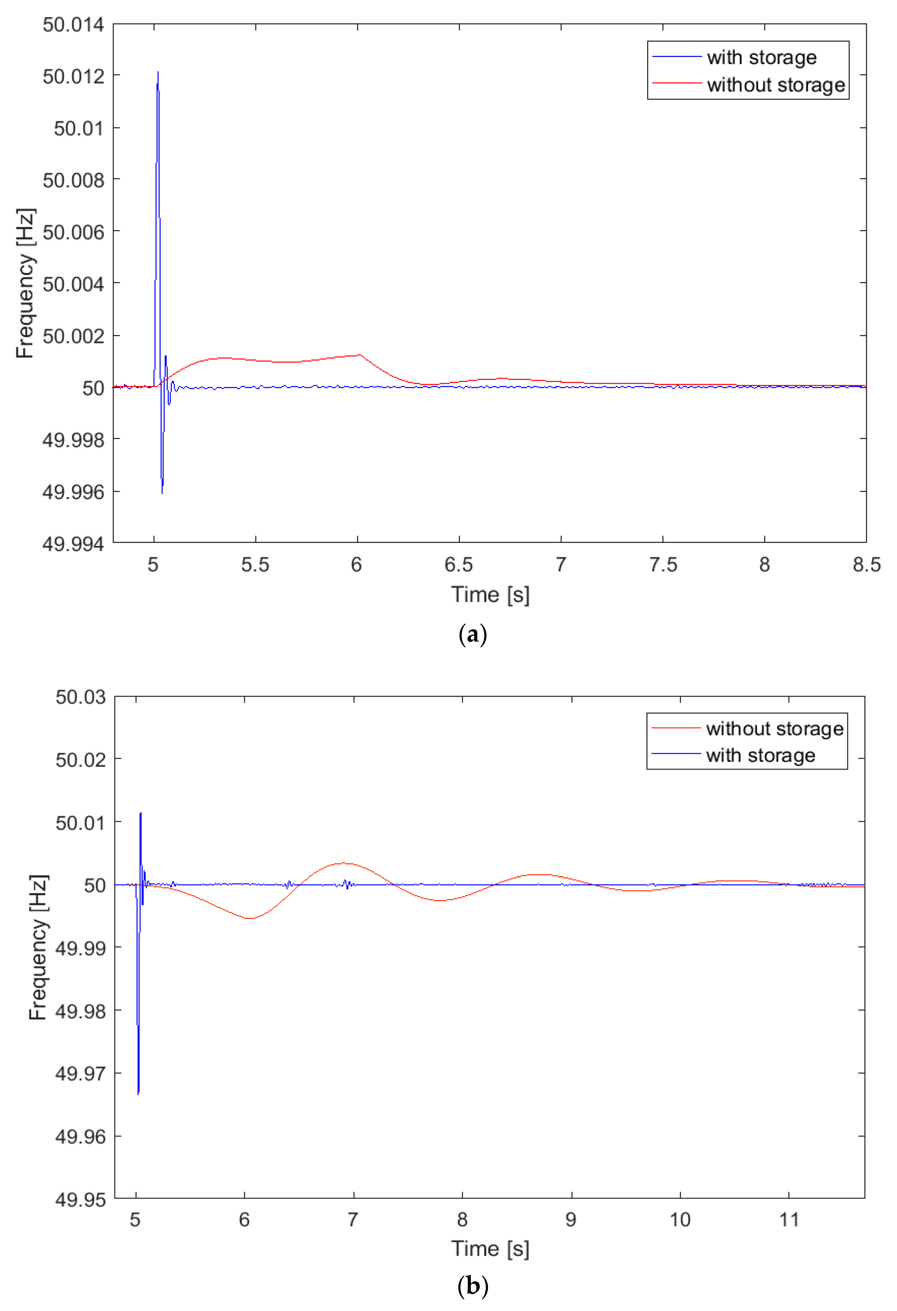
Frequency of the three-phase voltage waveform.
Indeed, such aspects inherent to HESS coupling to WTGs can strongly increase grid safety and stability.
Figure 5 illustrates the active power exchanges at the PCC in the cases of presence and absence of the considered HESS, respectively, for the step-up and step-down scenarios. Specifically, HESS allows the strong reduction in the power ramp when the wind power variation occurs for both the studied cases.
Concerning the response in terms of voltage waveform frequency at the PCC, the two simulated scenarios emphasize the benefits introduced by HESS connection to the WTG. Indeed, as illustrated in Figure 6, the frequency of the three-phase voltage waves is strongly reduced as regards the transient time, although the peak value is higher in both cases. In any case, for both considered scenarios, voltage waveform frequency variations are very close to the nominal value (i.e., set at 50 Hz) and within limits imposed by IEEE requirements for WTG continuous operation (i.e., 47–52 Hz), as indicated in [42]. Consequently, the significant reduction in the transient time is considered as the main outcome.
Table 3 lists the main results obtained from the simulated cases. Specifically, it can be noted how the active power variation, calculated with reference to the active power value at the PCC before the wind power step application, is greatly reduced thanks to HESS integration with respect to the case of storage absence. As a matter of fact, when the wind power step is applied, HESS allows the reduction in the active power variation down to about 3.1% and 4.8% for step-up and step-down scenarios, respectively. The corresponding values obtained for the no-storage case are of almost one order of magnitude greater, exceeding 30% and 42%, respectively.
Furthermore, the voltage waveform frequencies in all the investigated cases have been assessed in terms of amplitude, as reported in Table 3. In the analyzed topology, the frequency of the generator is completely decoupled from the grid frequency. The introduction of the HESS in the DC-link causes a higher amplitude with respect to the storage absence because it perturbs the DC-link with power injection. Nevertheless, the values never exceed the frequency limits for WTG continuous operation as already discussed above. Table 3 also reports the results in terms of the transient times, computed considering a settling time threshold value of 10%, associated with the voltage waveform frequencies. The strong reduction in the frequency transient time in the case of HESS implementation down to 0.26 s for the wind power step-up and 0.251 s for the step-down is evident. Such values are greatly lower than the corresponding outcomes of the simulations performed for the WTG directly connected to the grid without the HESS. Specifically, for the no-storage configuration 2.52 s and 5.79 s, respectively, duration is determined for the step-up and the step-down cases, demonstrating that the frequency of the voltage waveform stabilizes more quickly thanks to HESS’s presence.

5. Conclusions

In this paper, a PMSG wind turbine connected to the grid by means of a full-scale B2B converter has been assessed in terms of electric performances at the PCC, comparing the integration of a hybrid energy storage system connected to the DC-link with the case of storage absence. Specifically, this study aimed to investigate, through a comparative analysis between the scenario of storage integration and storage absence, the beneficial effects in terms of voltage waveform frequency and active power behavior at the PCC introduced by HESS under specific stressful production conditions. Moreover, the results demonstrate the outcomes of our previous paper regarding the HESS application to a WEC with a proper power management strategy based on SPSA, with the purpose of smoothing the power oscillations sent to the grid.
As the main outcomes of this work, HESS integration allows a reduction in the active power variation when the wind power step is applied at about 3% and 4.8%, respectively, for step-up and step-down scenarios in relation to more than 30% and 42% concerning the no-storage case. Furthermore, HESS coupling to the DC-link of the B2B converter is able to reduce the transient time of the voltage waveform at the PCC up to 89.7% in the case of a wind turbine power generation increase and to 95.7% in the scenario of a sudden power generation reduction.
Hence, in this research, it is demonstrated that HESS integration in offshore WECs can strongly reduce fluctuating behavior of such renewable sources, injecting a smoother power into the main grid while also increasing the electric performance at the PCC, contributing significantly to the massive penetration of renewables in the coming years. Future activities will be focused on the assessment of HESS integration into wind turbines in abnormal conditions, such as voltage swells, sags, faults and interruptions. This is to prove the effective benefits introduced by the battery flywheel storage system to guarantee grid stability and improve its dynamic response.

Author Contributions

Conceptualization, L.B. and D.Z.; methodology, D.P., D.A.C. and L.B.; software, D.P.; validation, D.P. and D.A.C.; formal analysis, P.A.O., L.B. and D.P.; investigation, D.P. and L.B.; data curation, P.A.O., D.P. and D.A.C.; writing—original draft preparation, D.P. and D.A.C.; writing—review and editing, L.B. and M.L. All authors have read and agreed to the published version of the manuscript.

Funding

This research received no external funding.

Institutional Review Board Statement

Not applicable.

Informed Consent Statement

Not applicable.

Data Availability Statement

Not applicable.

Conflicts of Interest

The authors declare no conflict of interest.

References

  1. Walter, O.; Tremel, A.; Prenzel, M.; Becker, S.; Schaefer, J. Techno-economic analysis of hybrid energy storage concepts via flowsheet simulations, cost modeling and energy system design. Energy Convers. Manag. 2020, 218, 112955. [Google Scholar] [CrossRef]
  2. Tiboaca, M.E.; Costinas, S.; Radan, P. Design of Short-Term Wind Production Forecasting Model using Machine Learning Algo-rithms. In Proceedings of the 12th International Symposium on Advanced Topics in Electrical Engineering (ATEE), Bucharest, Romania, 25–27 March 2021. [Google Scholar]
  3. Sanjeevikumar, P.; Sarojini, R.K.; Palanisamy, K.; Sanjeevikumar, P. Large Scale Renewable Energy Integration: Issues and Solutions. Energies 2019, 12, 1996. [Google Scholar] [CrossRef] [Green Version]
  4. Al-Shetwi, A.Q.; Hannan, M.; Jern, K.P.; Mansur, M.; Mahlia, T. Grid-connected renewable energy sources: Review of the recent integration requirements and control methods. J. Clean. Prod. 2019, 253, 119831. [Google Scholar] [CrossRef]
  5. Eltigani, D.; Masri, S. Challenges of integrating renewable energy sources to smart grids: A review. Renew. Sustain. Energy Rev. 2015, 52, 770–780. [Google Scholar] [CrossRef]
  6. Alhelou, H.H.; Golshan, M.E.H.; Hatziargyriou, N.D. A Decentralized Functional Observer Based Optimal LFC Considering Unknown Inputs, Uncertainties, and Cyber-Attacks. IEEE Trans. Power Syst. 2019, 34, 4408–4417. [Google Scholar] [CrossRef]
  7. Alhelou, H.A.H.; Cuffe, P. A Dynamic State Estimator Based Tolerance Control Method Against Cyberattack and Erroneous Measured Data for Power Systems. IEEE Trans. Ind. Inform. 2021. [Google Scholar] [CrossRef]
  8. Haesalhelou, H.; Parthasarathy, H.; Nagpal, N.; Agarwal, V.; Nagpal, H.; Siano, P. Decentralised Stochastic Disturbance Observer-Based Optimal Frequency Control Method for Interconnected Power Systems with High Renewable Shares. In Proceedings of the 2016 IEEE International Power Electronics and Motion Control Conference (PEMC), Varna, Bulgaria, 25–28 September 2016. [Google Scholar] [CrossRef]
  9. International Renewable Energy Agency Renewable Energy Statistics. 2021. Available online: https://www.arcadis.com/en/knowledge-hub/perspectives/global/2021/energy-transition?gclid=Cj0KCQiAqbyNBhC2ARIsALDwAsBgclyPh8MBJ4jqtucnf2RVpFaySYp38qPIxxPP-HEAkbr2v74g4pIaAkzIEALw_wcB (accessed on 2 December 2021).
  10. Colmenar-Santos, A.; Perera-Perez, J.; Borge-Diez, D.; Depalacio-Rodríguez, C. Offshore wind energy: A review of the current status, challenges and future development in Spain. Renew. Sustain. Energy Rev. 2016, 64, 1–18. [Google Scholar] [CrossRef]
  11. Mojumdar, R.R.; Himel, M.S.H.; Rahman, S.; Hossain, S.J. Electric Machines & Their Comparative Study for Wind Energy Conversion Systems (WECSs). J. Clean Energy Technol. 2015, 4, 290–294. [Google Scholar] [CrossRef] [Green Version]
  12. Smail, H.; Alkama, R.; Medjdoub, A. Optimal design of the electric connection of a wind farm. Energy 2018, 165, 972–983. [Google Scholar] [CrossRef]
  13. Pavese, C. Wind energy literature survey no. 33. Wind Energy 2014, 17, 1789–1795. [Google Scholar] [CrossRef]
  14. Dowds, J.; Hines, P.; Ryan, T.; Buchanan, W.; Kirby, E.; Apt, J.; Jaramillo, P. A review of large-scale wind integration studies. Renew. Sustain. Energy Rev. 2015, 49, 768–794. [Google Scholar] [CrossRef]
  15. Ciupăgeanu, D.-A.; Lăzăroiu, G.; Barelli, L. Wind energy integration: Variability analysis and power system impact assessment. Energy 2019, 185, 1183–1196. [Google Scholar] [CrossRef]
  16. Ren, G.; Liu, J.; Wan, J.; Guo, Y.; Yu, D. Overview of wind power intermittency: Impacts, measurements, and mitigation solutions. Appl. Energy 2017, 204, 47–65. [Google Scholar] [CrossRef]
  17. Liu, W.; Lund, H.; Mathiesen, B.V.; Zhang, X. Potential of renewable energy systems in China. Appl. Energy 2011, 88, 518–525. [Google Scholar] [CrossRef] [Green Version]
  18. Armghan, H.; Yang, M.; Armghan, A.; Ali, N.; Wang, M.; Ahmad, I. Design of integral terminal sliding mode controller for the hybrid AC/DC microgrids involving renewables and energy storage systems. Int. J. Electr. Power Energy Syst. 2020, 119, 105857. [Google Scholar] [CrossRef]
  19. Faisal, M.; Hannan, M.A.; Ker, P.J.; Hussain, A.; Bin Mansor, M.; Blaabjerg, F. Review of Energy Storage System Technologies in Microgrid Applications: Issues and Challenges. IEEE Access 2018, 6, 35143–35164. [Google Scholar] [CrossRef]
  20. Nadeem, F.; Hussain, S.M.S.; Tiwari, P.K.; Goswami, A.K.; Ustun, T.S. Comparative Review of Energy Storage Systems, Their Roles, and Impacts on Future Power Systems. IEEE Access 2018, 7, 4555–4585. [Google Scholar] [CrossRef]
  21. Suberu, M.Y.; Mustafa, M.W.; Bashir, N. Energy storage systems for renewable energy power sector integration and mitigation of intermittency. Renew. Sustain. Energy Rev. 2014, 35, 499–514. [Google Scholar] [CrossRef]
  22. Yoldaş, Y.; Önen, A.; Muyeen, S.; Vasilakos, A.V.; Alan, İ. Enhancing smart grid with microgrids: Challenges and opportunities. Renew. Sustain. Energy Rev. 2017, 72, 205–214. [Google Scholar] [CrossRef]
  23. Barelli, L.; Bidini, G.; Pelosi, D.; Ciupageanu, D.; Cardelli, E.; Castellini, S.; Lăzăroiu, G. Comparative analysis of AC and DC bus configurations for flywheel-battery HESS integration in residential micro-grids. Energy 2020, 204, 117939. [Google Scholar] [CrossRef]
  24. Spiliotis, K.; Gonçalves, J.E.; Saelens, D.; Baert, K.; Driesen, J. Electrical system architectures for building-integrated photovoltaics: A comparative analysis using a modelling framework in Modelica. Appl. Energy 2020, 261, 114247. [Google Scholar] [CrossRef]
  25. Planas, E.; Andreu, J.; Garate, J.I.; de Alegría, I.M.; Ibarra, E. AC and DC technology in microgrids: A review. Renew. Sustain. Energy Rev. 2015, 43, 726–749. [Google Scholar] [CrossRef]
  26. Grasso, F.; Paolucci, L.; Bacci, T.; Talluri, G.; Cenghialta, F.; D’Antuono, E.; De Giorgis, S. Simulation Model and Experimental Setup for Power Quality Disturbances Methodologies Testing and Validation. In Proceedings of the 2019 IEEE 5th International forum on Research and Technology for Society and Industry (RTSI), Firenze, Italy, 9–12 September 2019; pp. 359–363. [Google Scholar] [CrossRef]
  27. Su, H.J.; Huang, H.Y.; Chang, G.W. Power Quality Assessment of Wind Turbines by Matlab/Simulink. In Proceedings of the 2010 Asia-Pacific Power and Energy Engineering Conference, Chendu, China, 28–31 March 2010; pp. 1–5. [Google Scholar]
  28. Omar, R.; Rahim, N.A. Modeling and simulation for voltage sags/swells mitigation using dynamic voltage restorer (DVR). In Proceedings of the 2008 Australasian Universities Power Engineering Conference AUPEC 2008, Sydney, Australia, 14–17 December 2008. [Google Scholar]
  29. Khokhar, S.; Zin, A.A.M.; Mokhtar, A.S.; Ismail, N. MATLAB/Simulink based modeling and simulation of power quality disturbances. In Proceedings of the 2014 IEEE Conference on Energy Conversion (CENCON), Ohor Bahru, Malaysia, 13–14 October 2014; pp. 445–450. [Google Scholar] [CrossRef]
  30. Ojaghi, M.; Faiz, J.; Shahrouzi, H.; Alimohammadi, S. Induction motors performance study under various voltage sags using simulation. In Proceedings of the 2011 International Conference on Electrical Machines and Systems, Beijing, China, 20–23 August 2011. [Google Scholar] [CrossRef]
  31. Bhakkad, M.V.; Deshmukh, B. Generation of Voltage Sag for different loads and conditions using MATLAB SIMULINK. In Proceedings of the 2019 International Conference on Innovative Trends and Advances in Engineering and Technology (ICITAET), Shegaon, India, 27–28 December 2019; pp. 153–159. [Google Scholar] [CrossRef]
  32. Barelli, L.; Bidini, G.; Ciupageanu, D.A.; Micangeli, A.; Ottaviano, P.A.; Pelosi, D. Real time power management strategy for hy-brid energy storage systems coupled with variable energy sources in power smoothing applications. Energy Rep. 2021, 7, 2872–2882. [Google Scholar] [CrossRef]
  33. Barelli, L.; Ciupageanu, D.-A.; Ottaviano, A.; Pelosi, D.; Lazaroiu, G. Stochastic power management strategy for hybrid energy storage systems to enhance large scale wind energy integration. J. Energy Storage 2020, 31, 101650. [Google Scholar] [CrossRef]
  34. Vestas V80 Offshore—2.00 MW—Wind Turbine. Available online: https://en.wind-turbine-models.com/turbines/668-vestas-v80-offshore (accessed on 7 July 2021).
  35. Ruan, J. Detailed Modelling of a 1.5 MW Wind Turbine Based on Direct-Driven PMSG. Available online: https://it.mathworks.com/matlabcentral/fileexchange/41833-detailed-modelling-of-a-1-5mw-wind-turbine-based-on-direct-driven-pmsg?s_tid=srchtitle (accessed on 7 July 2021).
  36. Okedu, K.E.; Barghash, H. Enhancing the Transient State Performance of Permanent Magnet Synchronous Generator Based Variable Speed Wind Turbines Using Power Converters Excitation Parameters. Front. Energy Res. 2021, 9. [Google Scholar] [CrossRef]
  37. Okedu, K.E.; Muyeen, S.M.; Takahashi, R.; Tamura, J. Protection schemes for DFIG considering rotor current and DC-link voltage. In Proceedings of the 2011 International Conference on Electrical Machines and Systems, Beijing, China, 20–23 August 2011; pp. 1–6. [Google Scholar] [CrossRef]
  38. Mrcela, I.; Sumina, D.; Sacic, F.; Barisa, T. A wind turbine two level back-to-back converter power loss study. In Proceedings of the 2016 IEEE International Power Electronics and Motion Control Conference (PEMC), Varna, Bulgaria, 25–28 September 2016; pp. 308–314. [Google Scholar] [CrossRef]
  39. El Mokhi, C.; Addaim, A. Optimization of Wind Turbine Interconnections in an Offshore Wind Farm Using Metaheuristic Algorithms. Sustainability 2020, 12, 5761. [Google Scholar] [CrossRef]
  40. Christ, R.D.; Wernli, R.L. Chapter 7—Power and Telemetry. In The ROV Manual, 2nd ed.; Christ, R.D., Wernli, R.L., Eds.; Butterworth-Heinemann: Oxford, UK, 2014; pp. 141–161. ISBN 978-0-08-098288-5. [Google Scholar]
  41. Buck Converter—Increased Accuracy and Simulation Speed Using Interpolation in SimPowerSystems.—File Ex-Change—MATLAB Central. Available online: https://it.mathworks.com/matlabcentral/fileexchange/48381-buck-converter-increased-accuracy-and-simulation-speed-using-interpolation-in-simpowersystems (accessed on 23 November 2021).
  42. Rahman, S.; Khan, I.; Alkhammash, H.; Nadeem, M. A Comparison Review on Transmission Mode for Onshore Integration of Offshore Wind Farms: HVDC or HVAC. Electronics 2021, 10, 1489. [Google Scholar] [CrossRef]
Figure 1. Schematic layout of the modeled system with HESS integration.
Jmse 09 01413 g001
Figure 2. Detailed section of the wind turbine generator consisting of a PMSG and a full B2B converter.
Jmse 09 01413 g002
Figure 3. Battery equivalent circuit.
Jmse 09 01413 g003
Figure 4. Detailed section of the battery (a) and flywheel (b) sections, with their buck/boost converters.
Jmse 09 01413 g004
Figure 5. Active power exchanged with the grid at the PCC for the (a) step-up scenario and (b) step-down scenario, in the case of HESS presence (blue line) and absence (red line).
Jmse 09 01413 g005
Figure 6. Frequency of the voltage waveform at the PCC concerning HESS integration (blue line) and absence of storage (red line) in case of (a) step-up scenario and (b) step-down scenario.
Jmse 09 01413 g006
Table 1. PMSG parameters implemented for wind turbine modeling.
ParametersValueMeasurement Unit
Stator phase resistanceRs0.006
InductancesLd, Lq0.3mH
Flux linkageΨ1.48V.s
InertiaJ35,000kg.m2
Viscous dampingF0.01N.m.s
Pole pairsNp48-
Rated powerPrated2MW
Table 2. Li-ion battery parameters.
ParameterValue
Maximum capacity C m a x (Ah)500
Exponential zone capacity C e x p (Ah)26.5
Nominal voltage E 0 (V)450
Exponential zone capacity E e x p (V)425
Polarization constantK [Ah−1]0.00682
Internal resistanceRint (Ω)0.0001
Table 3. Main simulation results.
Transient Time (s)Frequency Amplitude (Hz)Active Power Variation (kW)Active Power Variation (%)
CaseHESSNo StorageHESSNo StorageHESSNo StorageHESSNo Storage
Step
Up
0.262.520.020.001226.12211.853.0630.49
Step down0.255.790.050.0179.32555.794.8342.35
Publisher’s Note: MDPI stays neutral with regard to jurisdictional claims in published maps and institutional affiliations.

