Article

Prediction of Maneuverability in Shallow Water of Fishing Trawler by Using Empirical Formula

1
Training Ship, Pukyong National University, Busan 48513, Korea
2
Division of Navigation Convergence Studies, Korea Maritime and Ocean University, Busan 49112, Korea
*
Author to whom correspondence should be addressed.
J. Mar. Sci. Eng. 2021, 9(12), 1392; https://doi.org/10.3390/jmse9121392
Submission received: 16 November 2021 / Revised: 30 November 2021 / Accepted: 4 December 2021 / Published: 6 December 2021
(This article belongs to the Special Issue Maritime Autonomous Vessels)

Abstract

:
The length between perpendiculars (LBP) of most fishing vessels is less than 100 m. Thus, they are not subject to the International Maritime Organization (IMO) maneuverability standards, affecting research on maneuverability. However, upon referencing the statistics of marine accidents related to vessel maneuvering, the number of marine accidents caused by fishing vessels is 3 to 5 times higher than that of merchant ships. Therefore, systematic and consistent research on the maneuverability characteristics of fishing vessels is surely required. In particular, a fishing vessel frequently enters and departs from the same port and often sails at high speed due to familiarity with the characteristics of the situation, which may cause maneuvering-related accidents. In this study, the maneuverability of a fishing vessel in shallow water was predicted using an empirical formula. The results of this study are expected to not only be of great help in conducting simulations when analyzing marine accidents involving fishing vessels, but will also provide unique parameters of fishing vessels that lead to developing autonomous vessels.

1. Introduction

The International Maritime Organization (IMO) approved the ship’s maneuverability standard in 2002 to prevent maritime accidents caused by the unique maneuverability problems of the ship itself. For this reason, a ship equipped with traditional propulsion and steering systems of length between the perpendiculars (LBP) of 100 m or more is subjected to a maneuverability test based on this standard after construction is complete [1]. On the other hand, most fishing vessels have an LBP of less than 100 m, so they are not subject to the IMO maneuverability standard. This has led to reduced demand for these predictions or trials, which means little data is available [2,3]. In other words, while the maneuverability studies for a vessel to which the IMO maneuverability criteria for 100 m length or longer are applied and are actively conducted from the design stage, this has not been the case with most types of fishing vessels of less than 100 m, and the results of studies conducted on merchant vessels have been accepted and applied as they are [4].
However, the shape of a ship depends on its specific purpose. In particular, fishing vessels and merchant ships have their own hull shape characteristics. For example, the block coefficient C b , which can have the maneuverability needed to quickly chase shoals of fish, and installing the fishing gear at the correct location, is similar to high-speed slender ships such as container ships or car carriers. The large length to beam ratio (L/B) to secure sufficient hull capacity and stability are similar to low-speed large ships such as Ultra Large Crude-oil Carriers (ULCC) or Very Large Crude-oil Carriers (VLCC) [2]. Therefore, when applying the results of research performed on merchant ships to fishing vessels, appropriate corrections are required [5]. Of course, the best would be to conduct a study similar or identical to the study performed on merchant ship types on fishing vessels. However, in reality, most fishing vessels with a length of less than 100 m are not required to conform to the IMO maneuverability standard. Also, when a marine accident occurs, the possibility of causing significant marine pollution is significantly lower than for merchant ships, and it is difficult to conduct certain types of research for various reasons, such as the high cost of constructing a model ship.
Nevertheless, it is necessary to conduct a study of the maneuverability of a fishing vessel. Referencing the statistics of marine accidents related to ship maneuvering over the past 5 years (2016–2020), out of a total of 2227 cases (excluding leisure craft and other vessels), 1673 cases (75.1%) of the collision accidents involved fishing vessels, more than three times higher than the 554 cases (24.9%) involving merchant ships. In the case of contact and grounding accidents, 665 cases (82.8%) were fishing vessels out of a total of 803 cases (excluding leisure crafts and other vessels), almost five times higher than that of 138 cases (17.2%) of merchant ships [6]. In other words, despite satisfying the criteria for IMO maneuverability, marine accidents such as those described above consistently occur. Of course, it is known that human factors play the biggest role in the cause of marine accidents [7,8,9,10,11,12,13], though the problem of the unique maneuverability of a ship cannot be underestimated.
In addition, systematic and consistent research on the maneuverability of fishing vessels can accumulate data that identify the unique hull shape characteristics of fishing vessels. Accumulation of data on these hull shape characteristics provides high accuracy of characteristic parameters for fishing vessel types in marine accident analysis and autonomous vessel development. Studies on the prediction of the maneuverability of fishing vessels have been carried out by Yoshimura [14,15,16,17], Dan [18], Lee [3,4,19], Kim [2,5,20], etc. [21,22,23,24,25,26,27], but a lot of research is still required.
Based on a review of the state of the art, the authors conducted a study to devise an empirical maneuverability prediction formula more suitable to fishing vessels [2,7]. Through the verification process, it has been confirmed that improved results were obtained in predicting the maneuverability of a fishing vessel [5]. In this study, by applying the empirical formula of Kijima et al., which includes correcting factors of the hydrodynamic coefficients of fishing vessel hull shape obtained from the corrected empirical formula, a study was performed to predict maneuverability in shallow water.

2. Mathematical Model

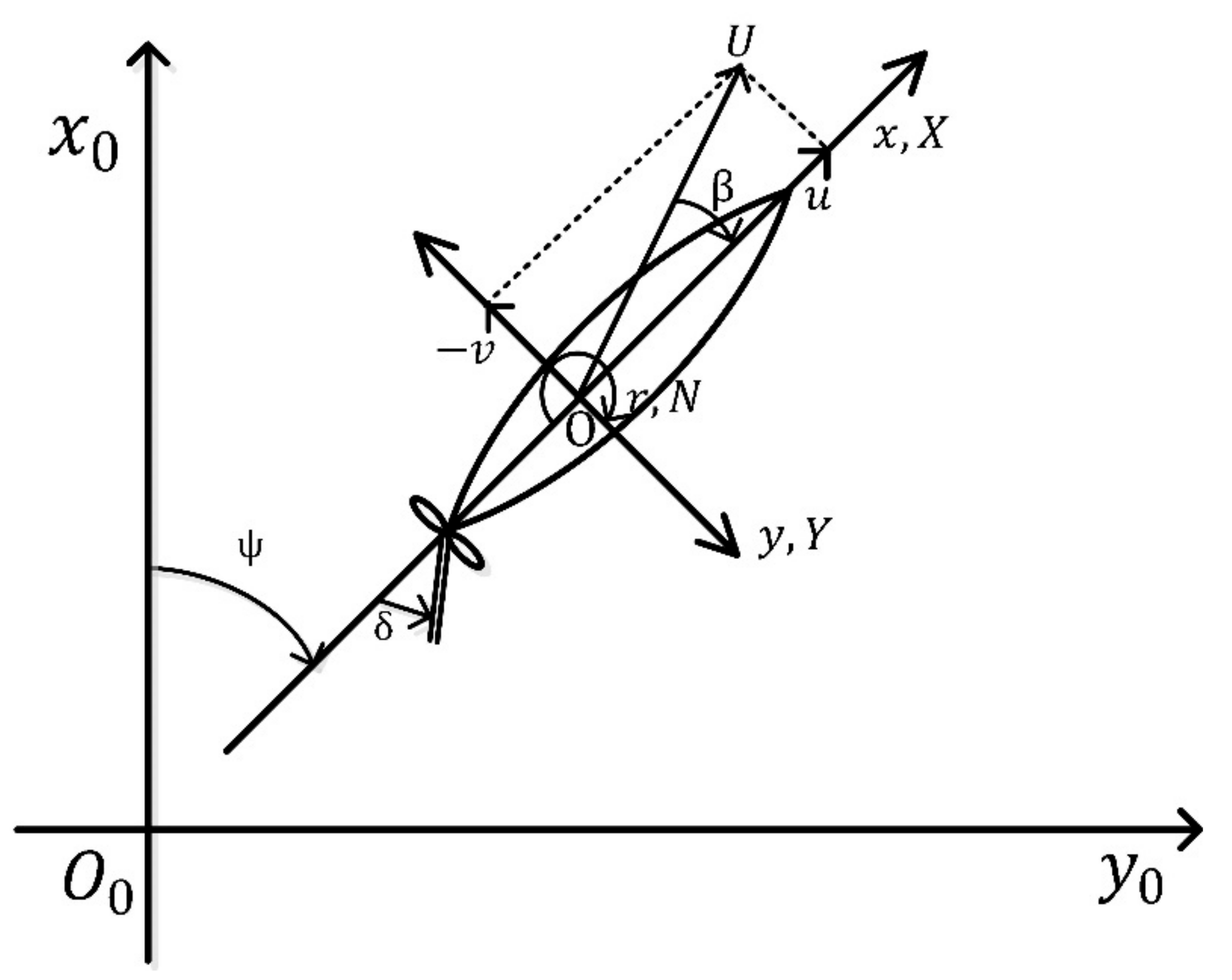
2.1. Coordinate System and Motion Equations

The equation of motion used in this study was derived from the right-handed orthogonal coordinate system shown in Figure 1. o 0 x 0 y 0 z 0 is the earth-centered fixed coordinate system, o x y z and is the hull body-fixed coordinate system with the mid-ship fixed at the origin o . Here, z 0 is oriented vertically downwards in the x 0 y 0 plane, and similarly, z is oriented vertically downwards in the x−y plane.
The maneuvering equation of motion can be expressed in various ways. In the Kijima et al. empirical formula used in this study, the drift angle β and the nondimensionalized angular velocity r were used, as shown in Equation (1).
m + m x L U U ˙ U cos β β ˙ sin β + m + m y r sin β = X m + m y L U U ˙ U sin β + β ˙ cos β + m + m x r cos β = Y I zz + i zz L U 2 U ˙ L r + U L r ˙ = N
m , m x , m y = m , m x , m y / 1 2 ρ L 2 d I zz , i zz = I zz , i zz / 1 2 ρ L 4 d X , Y = X , Y / 1 2 ρ L d U 2      N = N / 1 2 ρ L 2 d U 2 r = r L / U
The Kijima et al. empirical formula is based on the maneuvering modeling group (MMG) model [17,28]. It can be expressed as Equation (2) by dividing the external force terms X ,   Y ,   N on the right side of Equation (1) into hull, rudder, and propeller components, respectively. Here, the subscripts H, R, and P denote hull, rudder, and propeller [29].
X = X H + X R + X P Y = Y H + Y R N = N H + N R

2.2. Forces and Moment Affecting the Hull

The forces X H , Y H and moment N H affecting on the hull are calculated using the drift angle β and the nondimensionalized angular velocity r and it can be expressed as Equation (3) [30].
X H = X β r r sin β + X uu cos 2 β Y H = Y β β + Y r r + Y β β β β + Y rr r r + Y β β r β + Y β rr r β r N H = N β β + N r r + N β β β β + N rr r r + N β β r β + N β rr r β r

2.3. Forces and Moment from the Propeller

In general, the force generated by the propeller is the forward and backward force X P , if left-right force Y P and moment N P are omitted under the assumption that they are minute, they can be expressed as Equation (4) [29].
X P = C tP 1 t P 0 K T J P n 2 D P 4 / 1 2 LdU 2 K T J P = C 1 + C 2 J P + C 3 J P 2 J P = U cos β 1 w P / nD P

2.4. Forces and Moment from the Rudder

The forces X R , Y R and moment N R affecting the rudder is expressed as Equation (5), and t R , a H , x H are the main interaction coefficients affecting the rudder, propeller, and hull, and the normal force affecting the rudder F N also has a strong correlation with the interaction coefficients, as shown in Equation (6) [29].
X R = 1 t R F N sin δ Y R = 1 + a H F N cos δ N R = x R + a H x H F N cos δ
F N = A R / Ld C N U R 2 sin a R C N = 6.13 K R / K R + 2.25 U R 2 = 1 w R 2 1 + Cg s g s = η K 2 2 K s s / 1 s 2 η = D P / h R K = 0.6 1 w P / 1 w R s = 1.0 1 w P Ucos β / nP w R = w R 0 · w P / w P 0 a R = δ γ · β R β R = β 2 x R · r , x R 0.5

3. Empirical Formula

The method for predicting maneuverability at the design stage can be classified as a method using a database of similar or identical ships, constructing and testing a model, and a numerical simulation which is a mathematical method. Among them, the empirical formula, one of the numerical simulation methods, is mainly utilized in the case of fishing vessels. Although the accuracy is lower than that of the model test, it has the advantage of the execution process being relatively simple.
There are various empirical formulae developed for hull-shape merchant ships designed by each ship design laboratory, and they are corrected through consistent researches and revisions. However, since the process of deriving an empirical formula similar to this is technology belonging to each research institute, only a small portion of it is disclosed. On the other hand, the Kijima et al. empirical formula has been published using the specifications of the target ships used in the research for the process of deriving the empirical formula [29,31,32]. Also, since the proposed empirical formula concerning the shape of the stern for shallow water has been developed [33], the authors performed a study selecting the subjects based on the Kijima et al. empirical formula.

3.1. Kijima et al. Empirical Formula

The empirical formula used in this study is an empirical formula that does not consider the shape of the stern among all of the proposed Kijima et al. empirical formulas. This formula is suitable for predicting the ship’s maneuverability in deep water and is suitable for ships with conventional hull shapes, in particular those that have conventional stern shapes [29]. A typical equation is shown in Equation (7) below to derive linear coefficients among the hydrodynamic forces affecting the hull in the even keel state.
Y β = 1 2 π k + 1.4 C b B / L Y r m + m x = 1.5 C b B / L N β = κ N r = 0.54 κ + κ 2

3.2. Corrected Empirical Formula

As stated, research on the maneuverability of fishing vessels is lacking compared to merchant ships due to various reasons. The model test is rarely carried out due to cost and time-consuming considerations during the design stage, and there have also been many difficulties in securing performance data (resistance, self-propulsion, and propeller open water test) required to predict the maneuverability.
For these reasons, the authors conducted a study to derive a corrected empirical formula. It is expected to further improve the prediction of the maneuverability of fishing vessels by including the unique hull shape characteristic parameters of fishing vessels in the Kijima et al. empirical formula, which is widely used in shipbuilding practice [2,5,20]. The schematic processes are as follows:
(1)
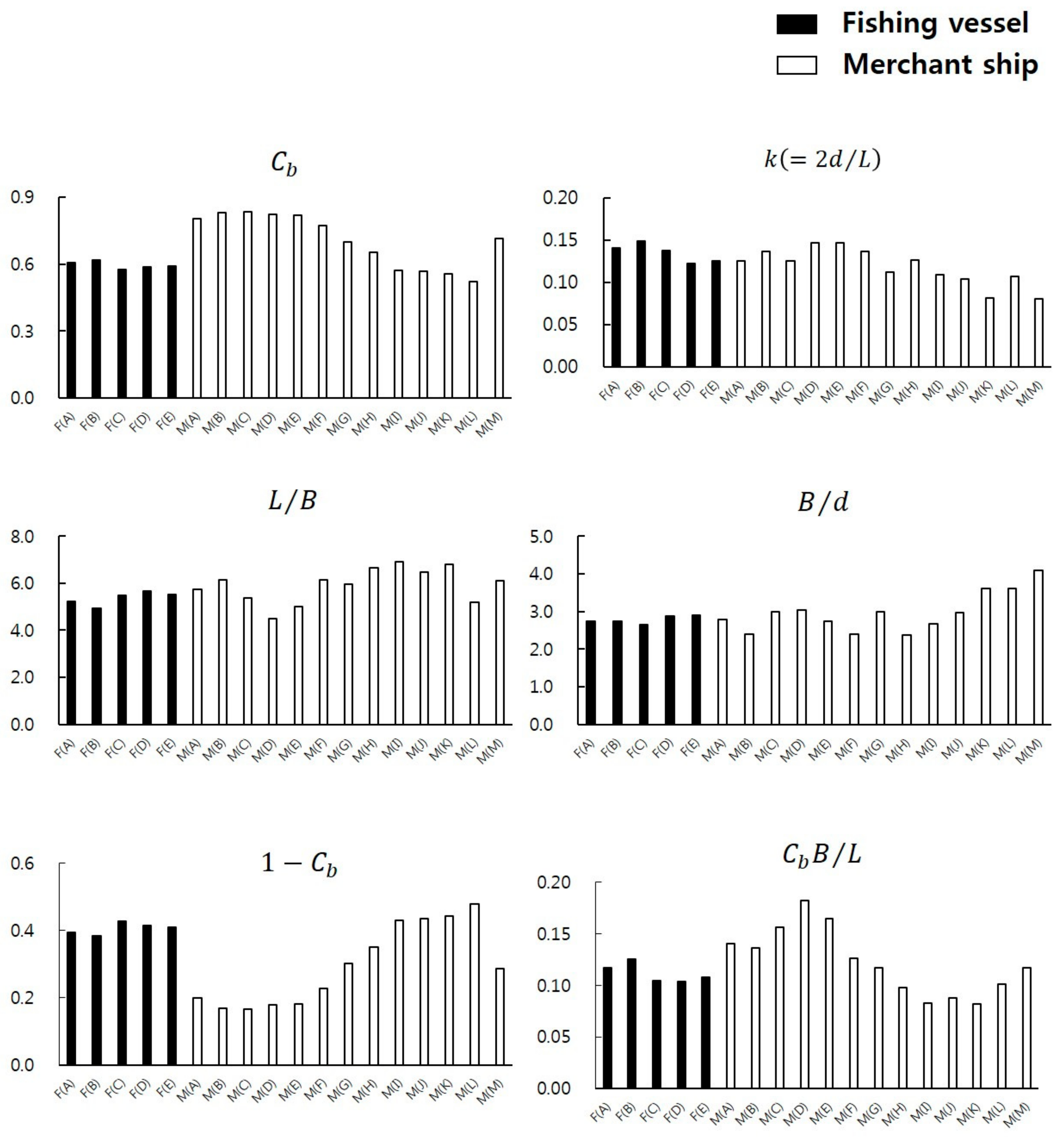
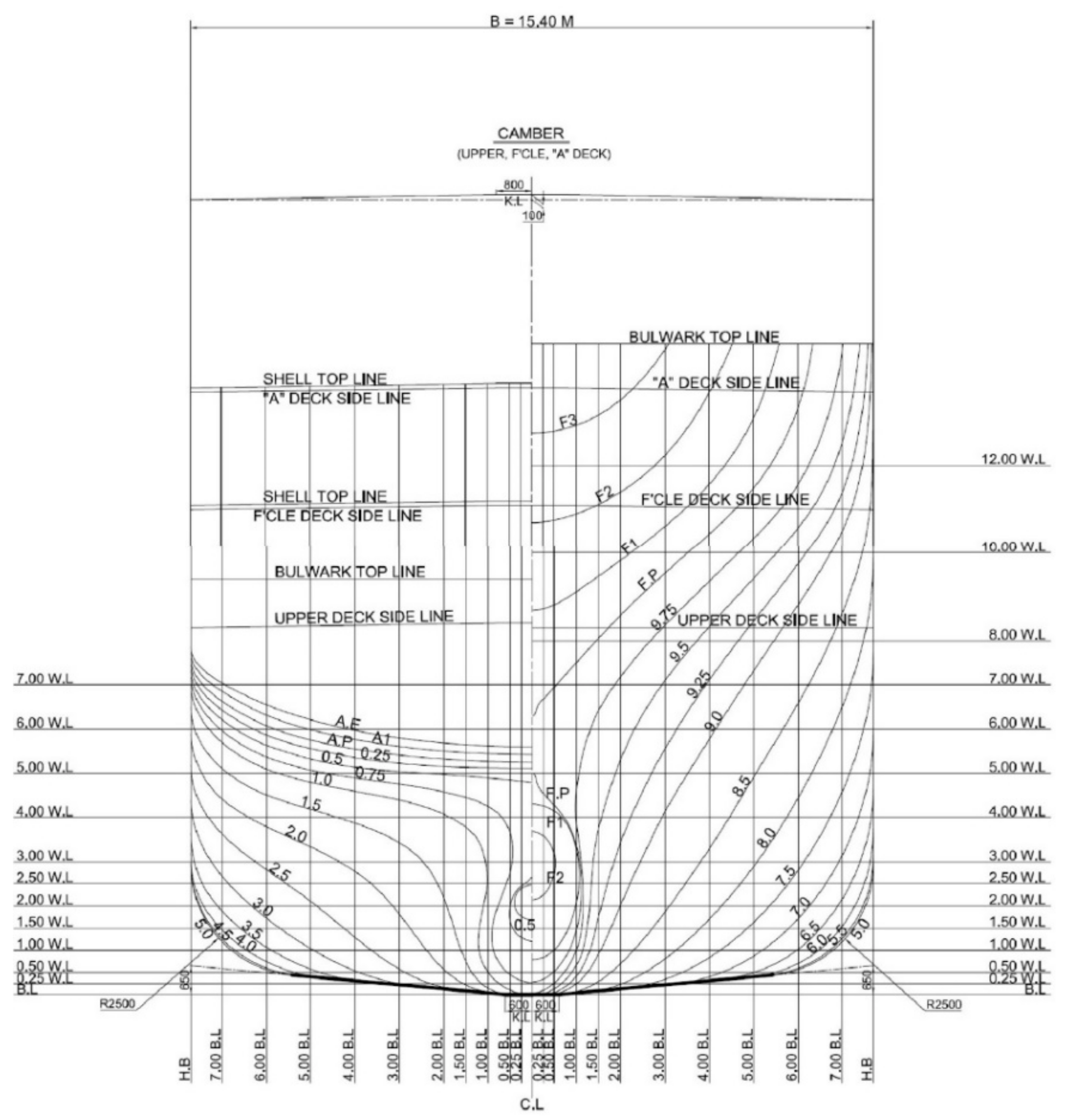
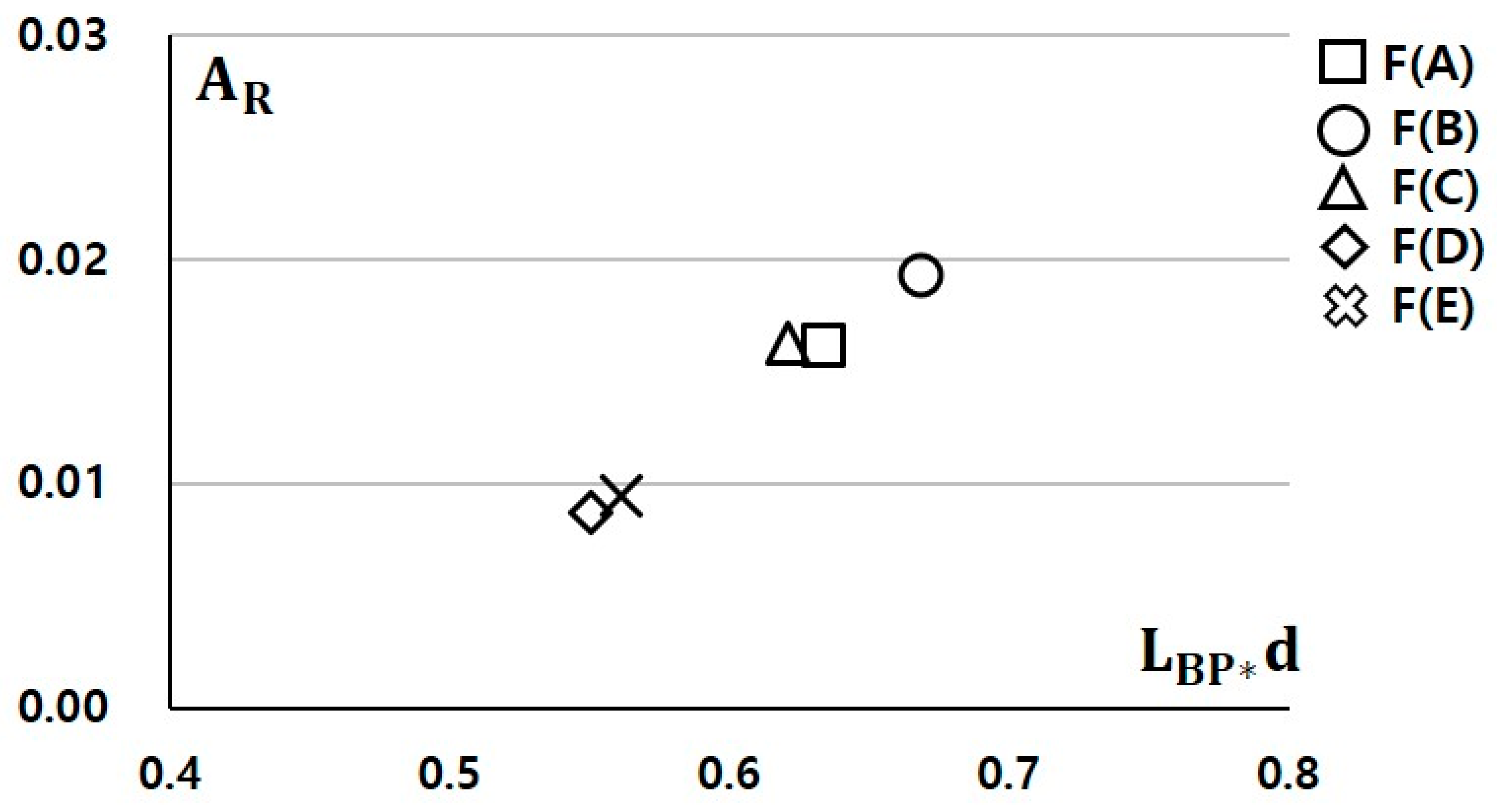
Prior to the study, the hull shape parameters of 5 model fishing vessels (5 Stern trawlers) used for deriving the corrected empirical formula were compared to 13 merchant ships (2 VLCCs, 3 ULCCs, 3 Cargo ships, 2 Container ships, 1 RO/RO ship, 1 Car carrier ship, and 1 LNG ship) included in the model test process for deriving the Kijima et al. empirical formula (Equation (7)). The Cb of the model fishing vessels used in the study had similar values to the high-speed slender ship (container and car carrier), while L/B was similar to a low-speed full ship (VLCC and ULCC). From these results, it can be seen that the fishing vessels have some distinct characteristics different from those of the merchant ships (Table 1, Figure 2).
(2)
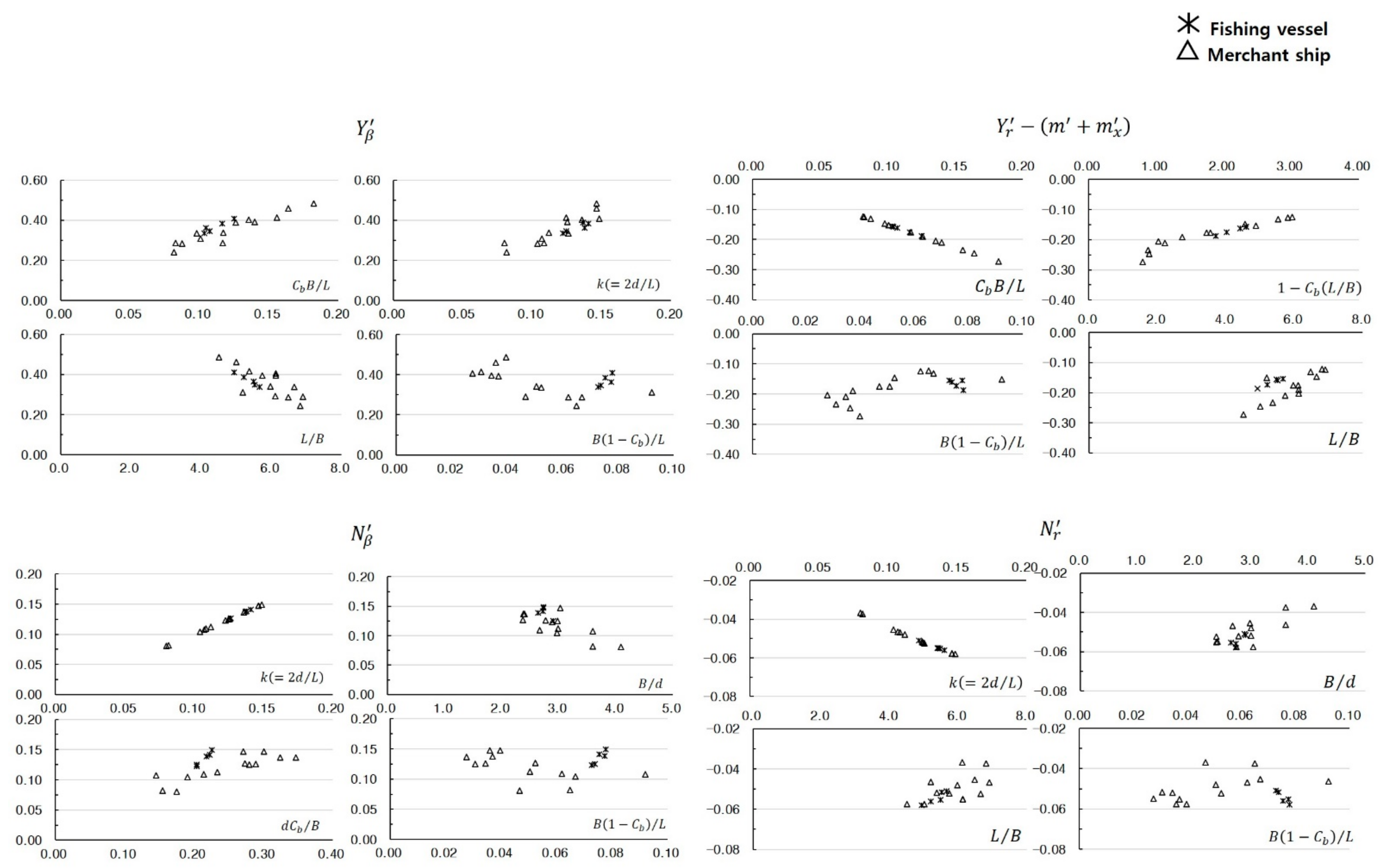
It was also discovered that hull shape parameter has a strong correlation to deriving the hydrodynamic coefficients adapting the empirical formula of Kijima et al. The coefficients showing the different tendencies of merchant ships and fishing vessels were recognized. Examples of typical hydrodynamic coefficients are shown in Table 2 and Figure 3.
(3)
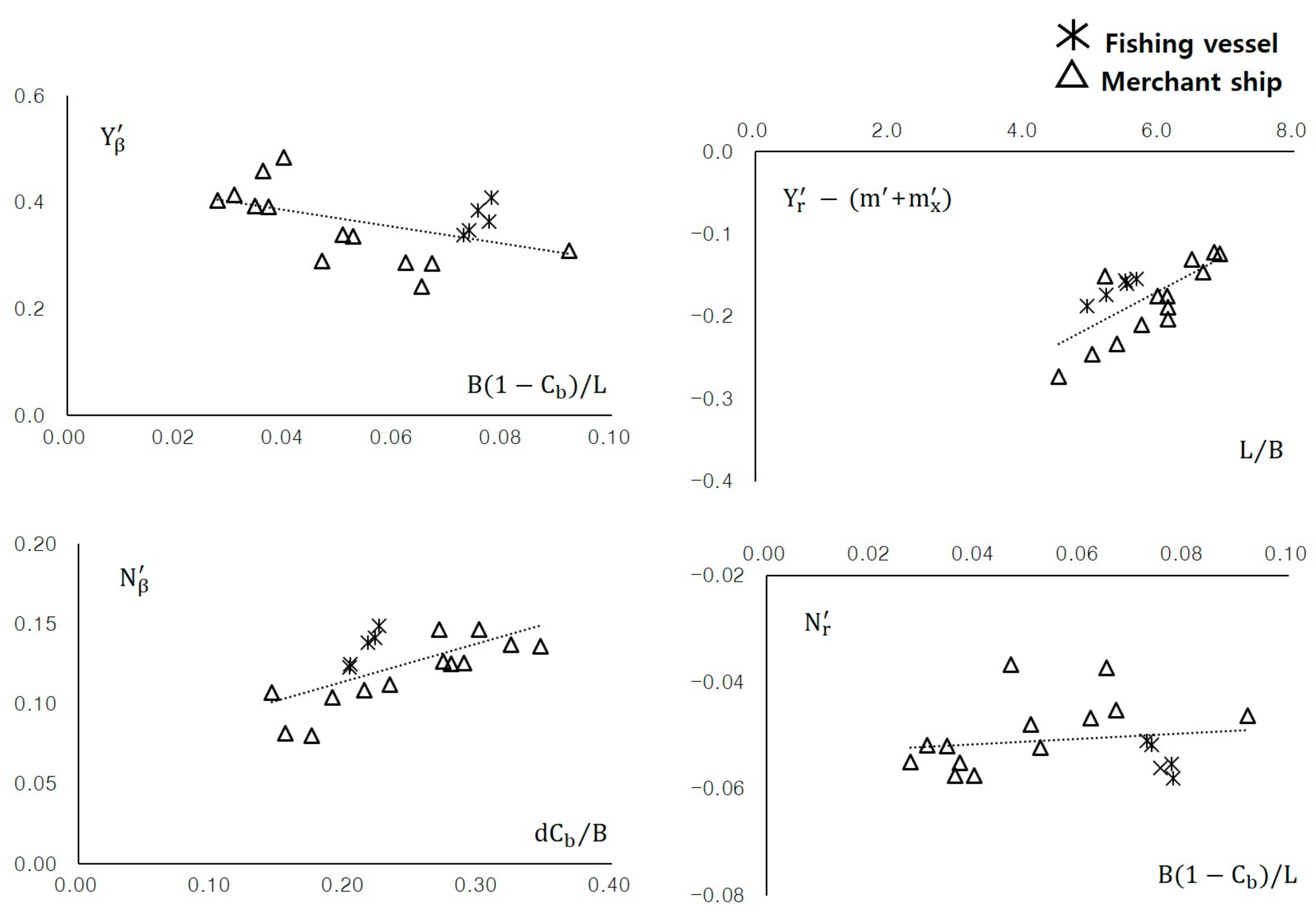
The correlation between the selected characteristics of hull shape parameters and the maneuvering hydrodynamic coefficients are shown and averaged using a trend line to derive a corrected empirical formula expected to be more suitable for fishing vessels (Figure 4). The equations for deriving the coefficients in the even keel state are shown in Equation (8) below.
Y β = 1.5747 1 C b / L / B + 0.4488 Y β β ' = 0.0417 × L / B + 0.541 Y r ' m + m x ' = 0.0432 × L / B 0.4276 Y r r ' = 0.7946 × 1 C b / L / B + 0.0563 Y β r r ' = 0.0993 × L / B + 0.0975 Y β β r ' = 2.7467 × k 0.6316 N β ' = 0.238 × C b / B / d + 0.0663 N β β ' = 0.016 × L / B + 0.0503 N r ' = 0.0515 × 1 C b / L / B 0.0537 N r r ' = 0.0144 × L / B + 0.0525 N β r r ' = 0.9156 × k + 0.0439 N β β r ' = 3.399 × 1 C b / L / B 0.0737 1 t R = 0.0127 × L / B + 0.8122 a H = 0.1107 × L / B + 1.1421 x H ' = 0.258 × L / B + 0.4603 1 w P 0 = 0.0227 × L / B + 0.5818 ε = 1.4308 × 1 C b / L / B + 0.9453 γ =   0.1608 × L / B 0.5764
(4)
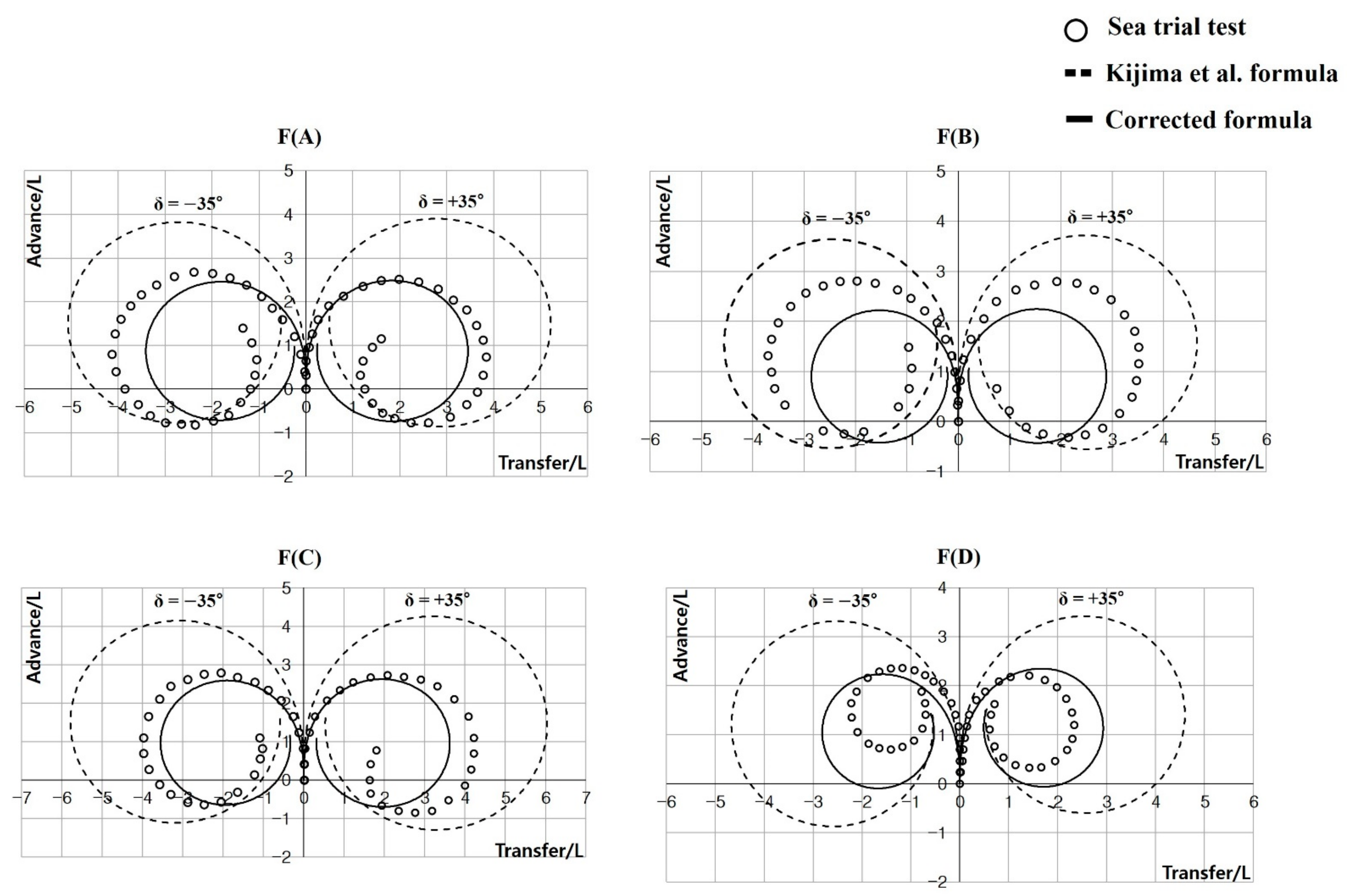
The results for maneuvering hydrodynamic coefficients of the 5 model fishing vessels were derived from the corrected empirical formula (Table 3), and the validity was verified by performing a turning movement simulation in 4 vessels, except for F(E), which was under construction at the time (Figure 5).
It can be confirmed that the corrected empirical formula in Figure 5 shows an improved result compared to the empirical formula developed for merchant ships in predicting the maneuverability of fishing vessels. However, since the corrected empirical formula proposed by the authors is limited to the hull shape parameters of the limited stern fishing trawlers, prediction errors may occur in predicting the maneuverability of fishing vessels having hull shape parameters out of the range presented below.
0.574 ≤ Cb 0.616, 4.93 ≤ L/B ≤ 5.76, 2.64 ≤ B/d ≤ 2.9

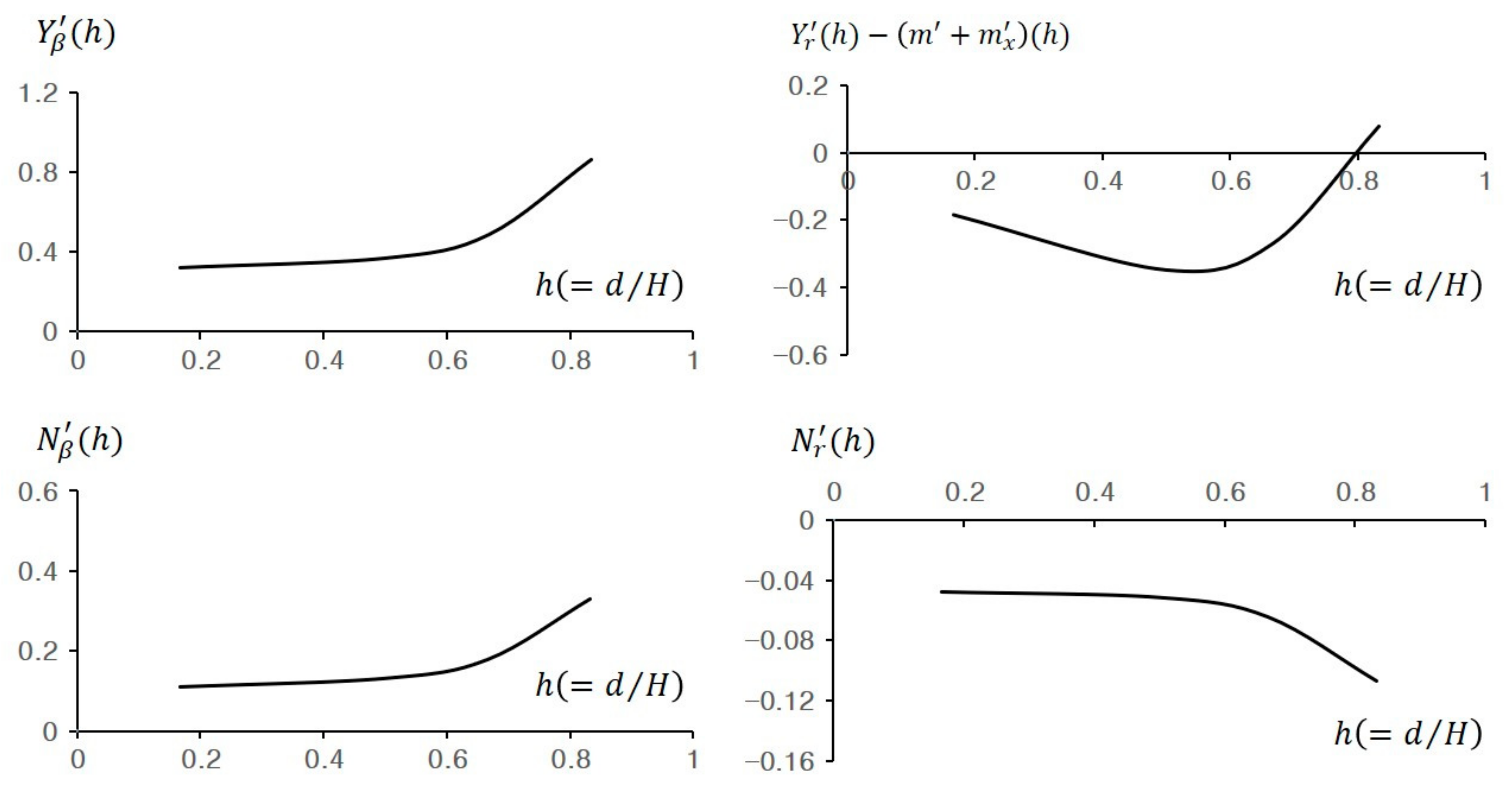
3.3. Kijima et al. Empirical Formula in Shallow Water including Correcting Factors

In modern times, all ships, including fishing vessels, have grown in size and often do not satisfy the operating conditions in ports. Accordingly, not only maneuvering in deep water but also maneuvering in shallow water has become an important research subject. However, since it is difficult to verify research results using real ships in shallow water, research is mainly conducted through numerical simulations or model tests. Studies using model tests such as free-running sailing obtain the most reliable results, though in reality, the method of estimating maneuverability by calculating hydrodynamic force coefficients is widely used. However, all hydrodynamic force coefficients are not linearized, and these values may cause a large error in estimating maneuverability. Fortunately, studies are being conducted to minimize these errors [34,35,36], and it is expected that a more accurate estimation of the nonlinear coefficients will be possible in the future. In this study, the maneuverability of a target fishing vessel was estimated using numerical simulation, which is somewhat uncertain, but results can be derived more easily. After that, the scope of the study will be gradually expanded through comparative analysis with the model tests.
To predict the maneuverability of ships in shallow water, correcting factors concerning the effect of ship-draft to water-depth ratio and the value of the maneuvering hydrodynamic coefficients used for predicting the maneuverability of the ships in deep water is required. Accordingly, Kijima and Nakiri [33] proposed an empirical formula for predicting ship maneuverability in shallow water, including correcting factors regarding the effect of ship-draft to water-depth ratio as shown in Equation (9). The equations for deriving the typical linear coefficients are shown in Equation (10).
D shallow = f h × D deep   f h = 1 / 1 h n h f h = 1 + a 1 h + a 2 h 2 + a 3 h 3
Y β : n = 0.40 C b B / d Y r m + m x a 1 = 5.5 C b B / d 2 + 26 C b B / d 31.5 a 2 = 37 C b B / d 2 185 C b B / d + 230 a 3 = 38 C b B / d 2 + 197 C b B / d 250 N β : n = 0.425 C b B / d N r : n = 7.14 κ + 1.5

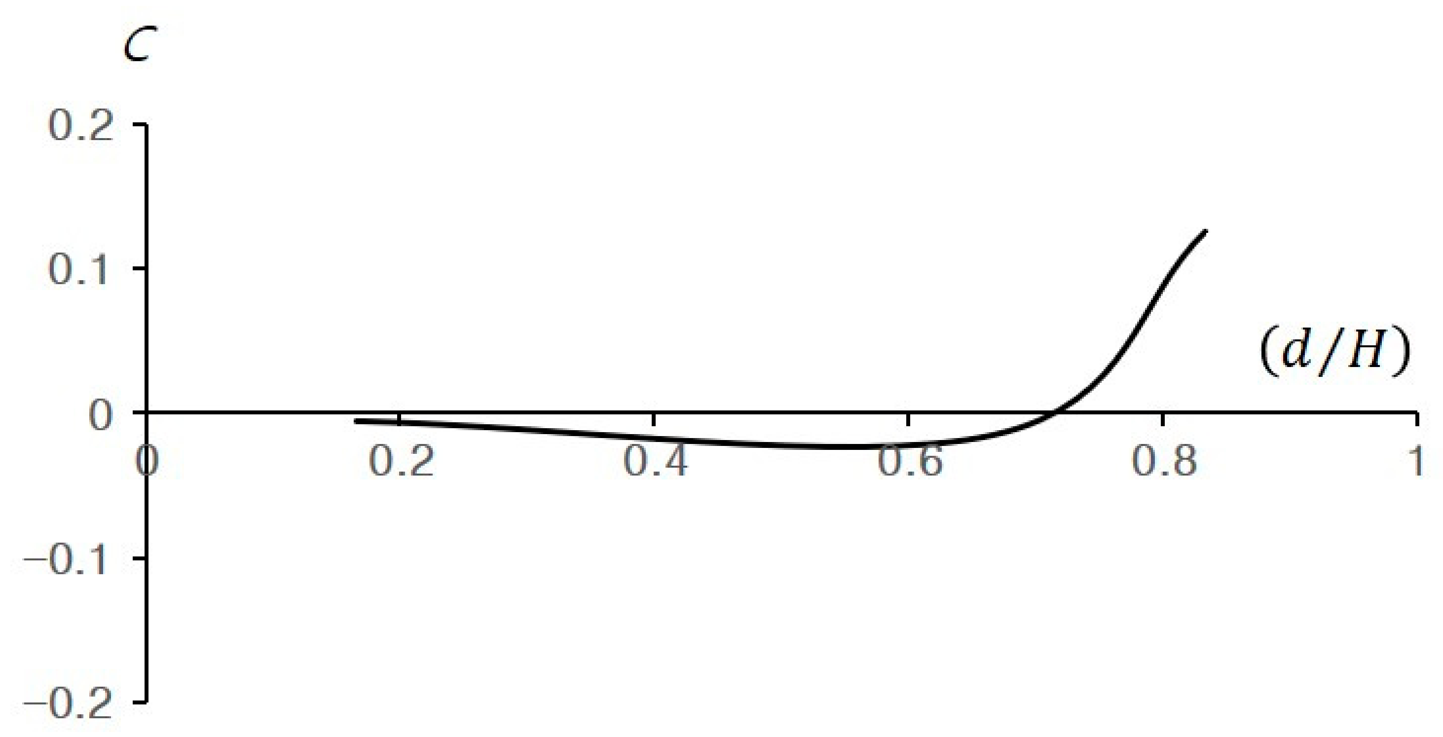
3.4. Discriminant for Course Stability

The course stability depends on the ship-draft to water-depth ratio, and the conditions for quantitatively determining the course stability of a ship using the maneuvering hydrodynamic coefficients are as shown in Equation (11) below. If the value of stability index C is (+), the course is stable, and if it is (−), it is determined as unstable. Since Y β Y r m + m x always represents a (+) value, so if the value of l r l β is (+), the course is stable, and if it is (−), the course is unstable [33].
C = Y β Y r m + m x × N r Y r m + m x N β Y β = Y β Y r m + m x × l r l β

4. Maneuverability Prediction of a Fishing Trawler

4.1. Target Fishing Vessel

The target fishing vessel is the F(E) in Table 1. The reason for selecting F(E) as a representation for the target fishing vessel was because it had been included in the corrected empirical formula derivation process, though the verification process could not be executed as it was under construction at the time. However, through the previous study, the verification of the turning motion test, 10/10 zig-zag test, etc., was verified, so based on the results, successive studies have been conducted to determine whether it is effective in shallow water. Outlined results related to the previous studies are briefly introduced in Section 4.2.
The target fishing vessel is a fisheries training ship having the hull shape of typical stern fishing trawlers, and the main specifications and body plan are shown in Table 4 and Figure 6.

4.2. Prediction of Maneuverability in Deep Water

4.2.1. Derivation of Maneuvering Hydrodynamic Coefficients

The basic purpose of this study is to verify whether the accuracy of the prediction for the maneuverability of a fishing vessel could be improved only by adding the characteristic parameters of the fishing vessels to the empirical formula developed for the merchant vessel type. To verify the validity of the corrected empirical formula, the maneuvering hydrodynamic coefficients of the target fishing vessel have been derived from the empirical formula of Kijima et al., and the corrected formula is shown in Equations (7) and (8). Therefore, all the hydrodynamic coefficients, including the interaction coefficients, were derived only through Equations (7) and (8). The typical linear coefficient values among the hydrodynamic forces affecting the hull are shown in Table 5 below.

4.2.2. Conditions for Maneuverability Evaluation

In order to evaluate the performance of a ship, a maneuvering trial must be executed on both port and starboard under the conditions specified below [1].
  • Deep, unrestricted water;
  • Calm environment;
  • Full load (summer load line draught, even keel condition);
  • Steady approach at the test speed.
However, in an actual ship test, because the external force is affecting as an irresistible force, it is impossible to perfectly harmonize the conditions of the simulation, and such a factor was taken into consideration. Table 6 shows the actual ship test and simulation conditions of the target fishing vessel [5,37].

4.2.3. Results of Maneuverability Evaluation

The simulation results of the maneuverability prediction of the target fishing vessel in deep water (Turning motion and 10/10 Zig-zag) are shown in Figure 7 below. It can be confirmed that the corrected empirical formula is closer quantitatively and qualitatively via actual ship test results than the Kijima et al. empirical formula. On this test, both evaluations were performed [5,37].
First, in the case of the turning motion test, both empirical formula results met the IMO maneuverability criterion. However, it can be confirmed that the corrected empirical formula result is way further quantitatively and qualitatively than the actual ship test result. At the same time, the shape of the port and starboard trajectories in the actual ship test are somewhat different, and based on the port turn it can be analyzed as follows:
a. The effect of the wind blowing from the port stern direction (relative bearing 205°–206°) is shown in Figure 7. During those time, the actual ship test temporarily blocked the turning of the bow just before the turn started, and the results tended to be slightly longer than when turning to starboard. Also, from the point when the bow started to turn, it helped the process, and it became rapidly faster than starboard turning (Figure 7a).
Next, in the case of the 10/10 Zig-Zag test, it can be confirmed that the result of the corrected empirical formula is closer to the actual ship test result compared to the result of the Kijima et al. empirical formula in connection to the tendency of the occurring location and trajectory of the overshoot angle. In the case of 1st overshoot angle, in the actual ship test and the corrected empirical formula, it occurred around 15 s, and for about 10 s, the slope became sharp. On the other hand, in the Kijima et al. empirical formula, 1st overshoot angle started to occur around 27 s, and a slight turning occurred. In the case of the 2nd overshoot angle, it also shows a tendency similar to the 1st overshoot angle (Figure 7b).
However, compared to the results of the two empirical formulas, the overshoot angle of the actual ship test was larger to a degree, which can be seen as a result of reflecting the unique characteristics of the target fishing vessel.
Many factors contribute to maintaining the stability of the ship course, and rudder area ratio plays a large role. When the rudder is large the rudder effect is better, though there are also disadvantages such as a decrease in speed due to resistance generation. Thus, the surface area ratio of the rudder is different depending on the purpose of construction. In the case of fishing vessels, the rudder area ratio is generally larger than that of merchant ships because it requires quick maneuverability to track the fish group. The rudder area ratio can be expressed as the ratio of the longitudinal cross-sectional surface area of the hull subsidence to the rudder area. At maximum draft, merchant ships are around 1/60 to 1/70, fishing vessels are 1/35 to 1/40, and warships are 1/30 to 1/50 [38].
Based on the above-mentioned theory, the results of comparing the rudder area ratio in 5 fishing trawler models (Table 1 and Table 2), which were used to derive a corrected empirical formula to check the effect of the rudder area ratio on the overshoot angle, is as shown in Table 7 and Figure 8 below.
F(A)~F(C) satisfy the other rudder area categories of fishing vessels, but it can be confirmed that F(D) and target fishing vessel F(E) belong to the rudder area ratio category of general merchant ships. This is because in the case of F(D) a flap rudder was installed, and the target fishing vessel was equipped with a thruster at the bow and stern, a function supporting the role of the basic rudder.
Meanwhile, such a result is an important basis for confirming that the maneuvering characteristics may vary depending on the propeller and rudder characteristics. Even though the vessel types have a similar hull shape, it is found that a systematic updating process is required by consistently adding new characteristic parameters as well as developing empirical formulas specific to each vessel type.

4.3. Prediction of Maneuverability in Shallow Water

4.3.1. Derivation of Maneuvering Hydrodynamic Coefficients

As a result of verification of the validation of the corrected empirical formula performed in deep water for the target fishing vessel, it was not possible to accurately predict the unique characteristics (interaction force-related) of the target fishing vessel. However, it was confirmed that improved results could be derived compared to using the Kijima et al. empirical formula developed for the merchant ship type. Therefore, in this section, the hydrodynamic coefficients in shallow water were derived by applying the correcting factor proposed by Kijima et al. to the target fishing vessel derived from the corrected empirical formula. Table 8 and Figure 9 show the change in the typical linear coefficient values based on the ship-draft to water-depth ratio among the hydrodynamic forces affecting the hull. As the ship-draft to water-depth ratio decreases, that is, as the water depth decreases, the Y β h and N β h values tend to increase, and the N r h value tends to decrease. In addition, the Y r m + m x h value shows the tendency to decrease until a ship-draft to water-depth ratio of H/d 1.5, and shows the tendency to rapidly increase thereafter. And it can be confirmed that all linear coefficient values have significant changes in the H/d 1.5 zone in common.

4.3.2. Discriminant of Course Stability by Ship-Draft to Water-Depth Ratio

The values of linear hydrodynamic coefficients of the target fishing vessel changed depending on the ship-draft to water-depth ratio. It was confirmed that a large change occurred in the zone of around H/d 1.5. As a result of judging the course stability by the ship-draft to water-depth ratio, from H/d 6.0 to 1.5, the course stability showed the tendency to become unstable at minute intervals, and then stabilized steeply immediately after H/d 1.5, and the value of ‘C’ was positive (+) at 1.2 (Figure 10). It can be concluded that when H/d becomes less than 1.5, the effect of external forces on maneuvering performance increases rapidly, such as frictional resistance affecting the hull increases and rudder effect decreases.

4.3.3. Conditions for Maneuverability Evaluation

The conditions for maneuverability in shallow water were set identically with the conditions for evaluating IMO maneuverability in deep water suggested in Section 4.2.2, except for item 1 (deep, unrestricted water). Table 9 below shows the simulated conditions for predicting target fishing vessel maneuverability in shallow water.

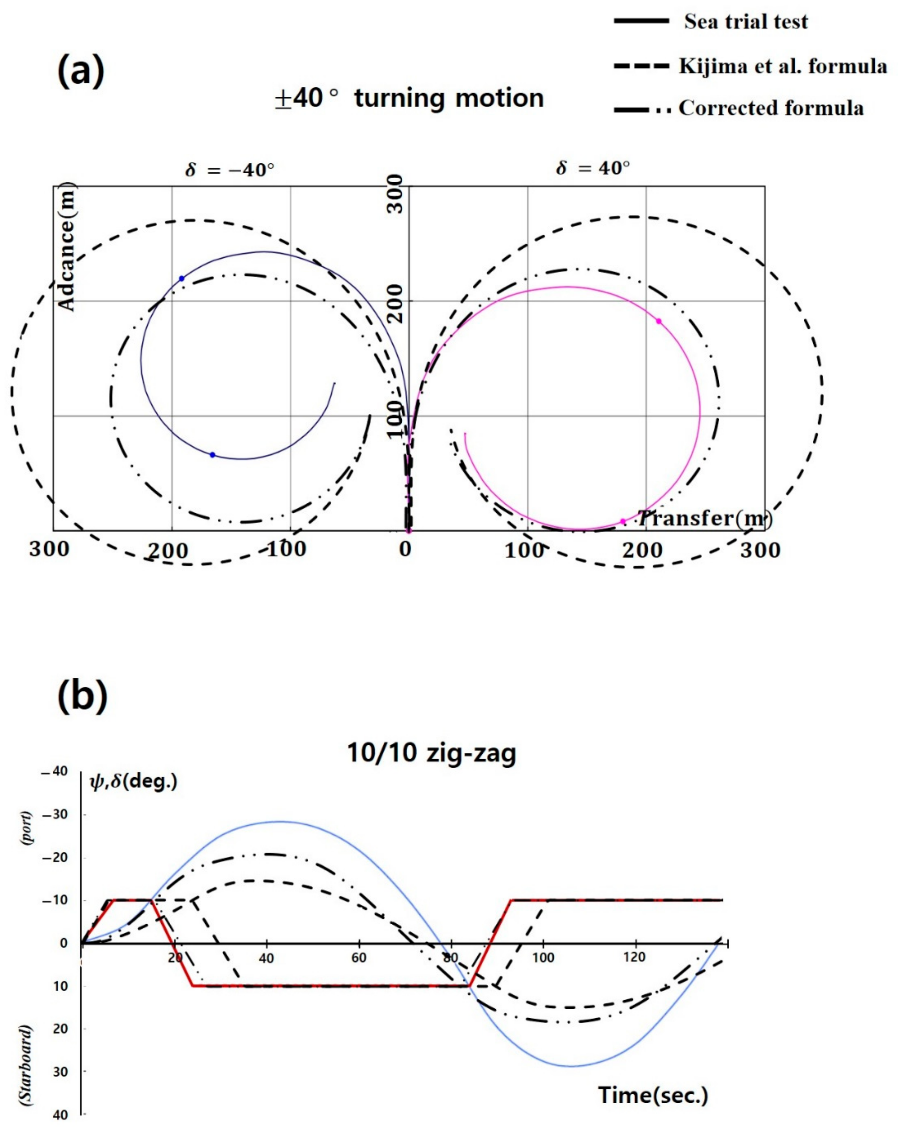
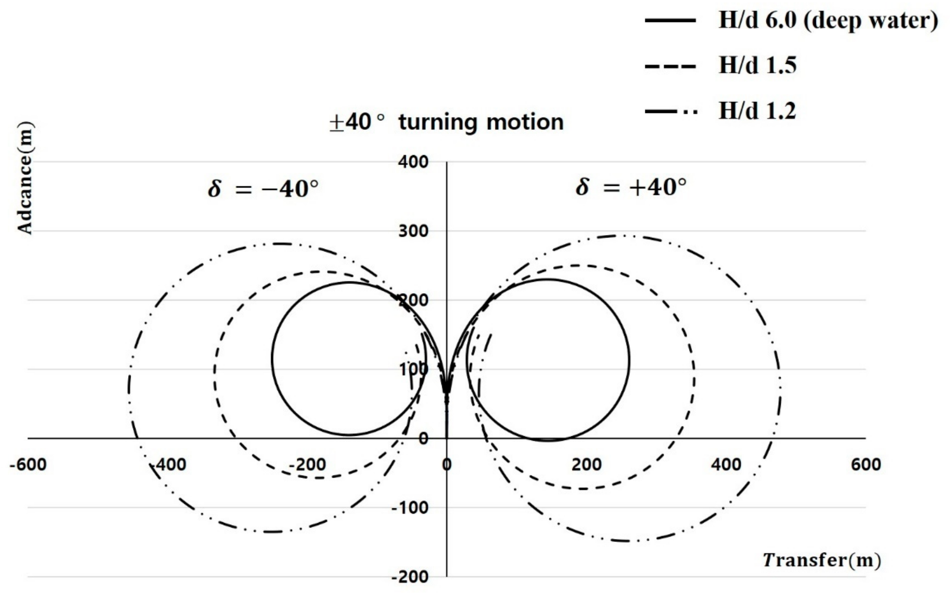
4.3.4. Simulation for Turning Motion

Table 10 and Figure 11 indicate the simulation results of the turning motion in shallow water ± 40 ° of the target fishing vessel. According to the ship-draft to water-depth ratio, the Advance was increased by an average of 60 m (0.7 L, 26%), and the Tactical Diameter was increased by an average of 203 m (2.4 L, 80%). This means that when entering shallow water, the turning radius does not increase identically overall, but increases more laterally. The reason for this is that as the ship starts to turn resistance rapidly increases and speed decreases, while the turning resistance moment increases rapidly as the angular velocity decreases [38].

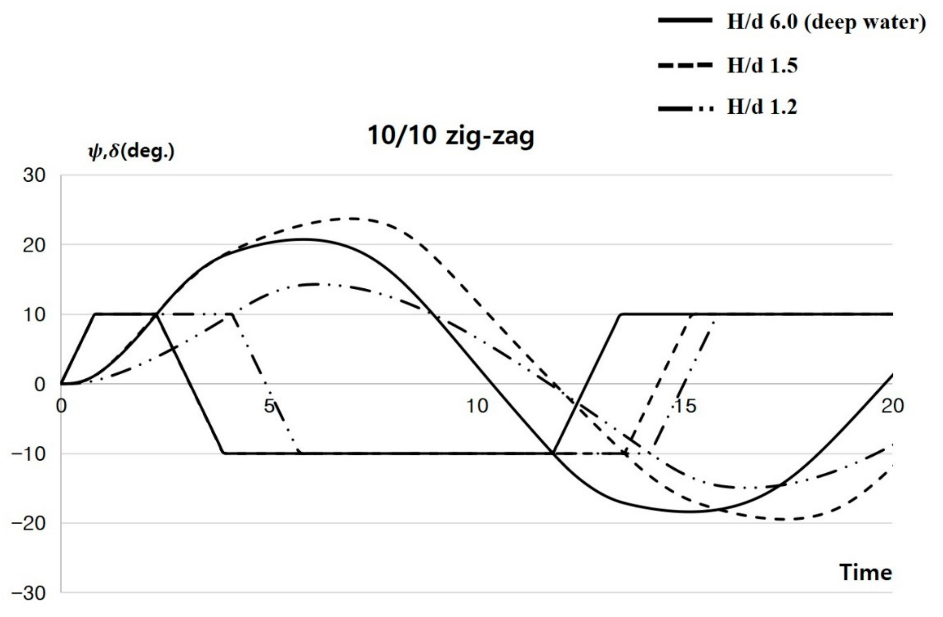
4.3.5. Simulation for 10/10 zig-zag

As a result of the 10/10 zig-zag simulation based on the ship-draft to water-depth ratio for the target fishing vessel, the overshoot angle of H/d 1.5 was larger than that of 6.0, but it was confirmed that the overshoot angle was smaller than 6.0 at 1.2 (Table 11, Figure 12). It was confirmed that a large change in the hydrodynamic coefficient values occurs around H/d 1.5, as shown in the course stability discriminant index (Figure 10) in Section 4.3.2. That is to say that, as in the turning motion test, the rudder pressure moment decreased around H/d 1.5, while the angular velocity decreased as the turning resistance moment increased. The turning curve is relatively slight, and the time of occurrence of the overshoot angle appears late.

5. Conclusions

Although fishing vessels generally meet the IMO maneuverability standard, according to statistics gathered over the last 5 years, it has been confirmed that marine accidents related to maneuverability, such as collision and grounding, occur 3 to 5 times more often to fishing vessels than to merchant ships. The human factor is the main cause of these accidents, but the problem of the maneuverability of the vessel cannot be overlooked. In particular, fishing vessels are often navigated at high speed in shallow water ports because they frequently enter and depart familiar ports, which causes accidents related to maneuvering.
Based on these accident statistics, the authors derived a corrected empirical formula assumed to be more accurate in predicting the maneuverability of a fishing vessel. A study has been conducted to predict the maneuverability in shallow water for the target fishing vessel. As a result, we found that the target fishing vessel shows a significant change in maneuverability near H/d 1.5, and it has been determined that this is mainly due to the decrease in the rudder pressure moment and the increase in the turning resistance moment, among various reasons.
Since this study is about a single newly built trawler, there may be limitations in applying these results to all types of fishing vessels, and reliability issues may be raised.
However, during the research process, the validity of the corrected empirical formula was confirmed once again, and it showed great significance in estimating maneuverability in shallow water using the hydrodynamic force coefficients derived from the corrected empirical formula. It was also able to determine possible improvements in predicting the maneuverability of fishing vessel types.
It is expected that the accumulation of the ship shape-related data of the fishing vessel types obtained from this study will be of great help in performing simulations for the analysis of fishing vessel marine accidents, as well as providing the unique parameters of the type of fishing vessels in the development of autonomous vessels.

Author Contributions

Conceptualization, S.-H.K.; methodology, S.-H.K.; software, C.-K.L.; analysis, S.-H.K.; writing—original draft preparation, Y.-B.C.; writing—reviewing and editing, C.-K.L.; supervision, S.-H.K. All authors have read and agreed to the published version of the manuscript.

Funding

This research received no external funding.

Institutional Review Board Statement

Not applicable.

Informed Consent Statement

Not applicable.

Data Availability Statement

The data used to support the findings of this study are available from the corresponding author upon request.

Acknowledgments

This research was supported by the ‘Development of Autonomous Ship Technology (20200615)’ funded by the Ministry of Oceans and Fisheries (MOF, Korea).

Conflicts of Interest

The authors declare no conflict of interest.

Nomenclature

A R rudder area
a R effective rudder inflow angle
a H rudder force increase factor
C coefficient for starboard and port rudder, stability index
C N rudder normal force gradient coefficient
C tP constants
C 1 ,   C 2 ,   C 3 constants
D P propeller diameter
D s h a l l o w coefficients in the shallow water
D d e e p coefficients in the deep water
F N normal force acting on the rudder/nondimensionalized
f a correcting factor
h d / H , ship-draft to water-depth ratio
h R rudder height
I zz ,   i zz inertia moment of z axis direction, added inertia moment/nondimensionalized
J P advance coefficient
K R aspect ratio of the rudder
K T thrust coefficient
m ,   m x ,   m y mass of ship, added mass of x axis direction, added mass of y axis direction/nondimensionalized
n propeller revolution
nP propeller revolution
S slip ratio
t P 0 thrust deduction coefficient in straight forward moving direction
t R steering deduction factor
U , β , δ resultant velocity, drift angle, rudder angle
U R effective rudder inflow speed
u ,   v ,   r velocity components at the center of gravity of ship and yaw rate about z axis
w P effective wake coefficient at the position of the propeller
w R effective wake coefficient at the position of the rudder
w P 0 effective wake coefficient at the position of the propeller in straight forward moving direction
w R 0 effective wake coefficient at the position of the rudder in straight forward moving direction
x H distance between C.G and the center of additional lateral force/nondimensionalized
x R longitudinal coordinate of the position of the rudder/nondimensionalized
β R effective inflow angle to the rudder in maneuvering motion/nondimensionalized
δ rudder angle
k 2 d / L
γ flow straightening coefficient
1 w P effective wake fraction at the position of the propeller
· (dot)derivative with respect to time
(prime)nondimensionalized quantity

References

  1. IMO MSC 76/23. “Standards for Ship Manoeuvrability” Report of the Maritime Safety Committee on Its 76th Session-Annex 6. Resolut. MSC 2002, 137, 1–6. [Google Scholar]
  2. Kim, S.H. A Study on the Improvement of the Accuracy of Fishing Vessels Manoeuvrability Prediction. Ph.D. Thesis, Korea Maritime and Ocean University, Busan, Korea, 2020. [Google Scholar]
  3. Lee, C.K.; Kim, S.H.; Lee, J.G.; Lee, S.M.; Kim, M.S. A Study on the Characteristics of Manoeuvrability of Fishing Vessel. J. Korean Soc. Fish. Ocean Technol. 2018, 54, 239–245. [Google Scholar] [CrossRef]
  4. Lee, C.K.; Kim, S.H.; Yim, J.B.; Lee, S.M. Study on the Maneuvering Characteristics of a Fishing Vessel in Shallow Water. Nav. Eng. J. 2019, 131, 95–104. [Google Scholar]
  5. Kim, S.H.; Lee, C.K. Estimation of Maneuverability of Trawl Fishing Vessel Using an Analytical Method. J. Mar. Sci. Eng. 2021, 9, 854. [Google Scholar] [CrossRef]
  6. Korea Maritime Safety Tribunal (KMST). Statistical Data of Maritime Accidents and Casualty. 2020. Available online: https://www.kmst.go.kr/kmst/statistics/annualReport/selectAnnualReportList.do (accessed on 10 August 2021).
  7. Lee, M.K.; Park, Y.S. Collision Prevention Algorithm for Fishing Vessels Using WAVE Communication. J. Mar. Sci. Eng. 2020, 8, 115. [Google Scholar] [CrossRef] [Green Version]
  8. Lee, M.K.; Park, Y.S.; Park, S.W.; Lee, E.K.; Park, M.J.; Kim, N.E. Application of Collision Warning Algorithm Alarm in Fishing Vessel’s Waterway. Appl. Sci. 2021, 11, 4479. [Google Scholar] [CrossRef]
  9. Mohamed, A.Z.; Abdulrahman, M.B. Occupational Safety and Health Conditions Aboard Small- and Medium-Size Fishing Vessels: Differences among Age Groups. Int. J. Environ. Res. Public Health 2017, 14, 229. [Google Scholar] [CrossRef] [Green Version]
  10. Rasmussen, H.B.; Ahsan, D. Injuries and Fatalities in Danish Commercial Fishing Fleet in 1998–2016. Safety 2018, 4, 13. [Google Scholar] [CrossRef] [Green Version]
  11. Alvite-Castro, J.; José, A.O.; Vergara, D.; Ángel, M.C.; Bouzón, R. A New Design Criterion to Improve the Intact Stability of Galician Small Fishing Vessels. J. Mar. Sci. Eng. 2020, 8, 499. [Google Scholar] [CrossRef]
  12. Kim, S.H.; Kim, H.S.; Lee, Y.W. The Causes and Counterplan for Marine Casualties of Fishing Vessels According to the Fishing Types. J. Korean Soc. Fish. Ocean Technol. 2020, 56, 246–257. [Google Scholar] [CrossRef]
  13. Jung, C.H. A Study on the Improvement of Safety by Accidents Analysis of Fishing Vessels. J. Fish. Mar. Sci. Educ. 2018, 30, 179–186. [Google Scholar]
  14. Yoshimura, Y.; Ma, N.; Suzuki, S.; Kajiwara, Y. Manoeuvring Performance of the Fishing vessel Modified by a Bulge. J. Soc. Nav. Archit. Jpn. 2002, 192, 37–46. [Google Scholar] [CrossRef]
  15. Yoshimura, Y.; Ma, N. Manoeuvring Prediction of Fishing vessel. In MARSIM 03’Conference Proceedings; RC-29-1-10; The Society of Naval Architects of Japan, Japan Institute of Navigation and International Marine Simulator Forum: Kanazawa, Japan, 2003. [Google Scholar]
  16. Yoshimura, Y.; Masumoto, Y. Hydrodynamic Force with Medium High Speed Merchant Ships Including Fishing Vessels and Investigation into a Manoeuvring Prediction Method. J. Jpn. Soc. Nav. Archit. Ocean Eng. 2011, 14, 63–73. [Google Scholar] [CrossRef] [Green Version]
  17. Yoshimura, Y.; Yasukawa, H. Introduction of MMG Standard Method for Ship Maneuvering Predictions. J. Mar. Sci. Technol. 2015, 20, 37–52. [Google Scholar] [CrossRef] [Green Version]
  18. Obreja, D.; Nabergoj, R.; Crudu, L.; Păcuraru-Popoiu, S. Identification of hydrodynamic coefficients for manoeuvring simulation model of a fishing vessel. Ocean Eng. 2010, 37, 678–687. [Google Scholar] [CrossRef]
  19. Lee, C.K.; Kim, S.H.; Lee, S.M.; Yim, J.B. Study on the Manoeuvring prediction of a fishing vessel. Nav. Eng. J. 2019, 131–134, 101–109. [Google Scholar]
  20. Kim, S.H.; Lee, C.K.; Lee, S.M. Estimation of Maneuverability of Fishing Vessel Considering Hull-Form Characteristics. J. Mar. Sci. Eng. 2021, 9, 569. [Google Scholar] [CrossRef]
  21. Kim, K.Y. Manoeuverabilities of the M.S “SAEBADA”. J. Korean Soc. Fish. Ocean Technol. 1979, 12, 209–215. [Google Scholar]
  22. Kim, M.S.; Shin, H.O.; Kang, K.M.; Kim, M.S. Variation of Turning Circle by the Rudder Angle and the Ship’s Speed. J. Korean Soc. Fish. Ocean Technol. 2005, 41, 156–164. [Google Scholar] [CrossRef]
  23. Ahn, Y.H.; Park, M.H.; Choi, C.M.; Chung, Y.J. A Study on the Maneuverabilities of the Training ship M.S. A-RA. J. Korean Soc. Fish. Ocean Technol. 2001, 37, 275–284. [Google Scholar]
  24. An, Y.S.; Kang, I.K.; Kim, H.S.; Kim, J.C.; Kim, M.S.; Jo, H.J.; Lee, C.K. A Study on the Manoeuvrability of T/S SAEBADA by Real sea trials. J. Korean Soc. Fish. Ocean Technol. 2005, 41, 289–295. [Google Scholar] [CrossRef] [Green Version]
  25. Kim, M.S.; Shin, H.I.; Kim, J.H.; Kang, I.K. A Study on the Maneuverabilities of the T.S KAYA. J. Fish. Mar. Sci. Educ. 2009, 21, 59–67. [Google Scholar]
  26. Huang, J.; Xu, C.; Xin, P.; Zhou, X.; Sutulo, S.; Soares, C.G. A Fast Algorithm for the Prediction of Ship-Bank Interaction in Shallow Water. J. Mar. Sci. Eng. 2020, 8, 927. [Google Scholar] [CrossRef]
  27. Hong, C.B.; Lee, S.M. A Study on Barge-Bank Interaction Forces Considering the Reflected Waves. J. Mar. Sci. Eng. 2020, 8, 451. [Google Scholar] [CrossRef]
  28. Ogawa, A.; Koyama, T.; Kijima, K. MMG report-I, on the Mathematical Model of Ship Manoeuvring. Bull. Soc. Nav. Archit. Jpn. 1977, 575, 22–28. [Google Scholar]
  29. Kijima, K.; Katsuno, T.; Nakiri, Y.; Furukawa, Y. On the Manoeuvring Performance of a Ship with the Parameter of Loading Condition. J. Soc. Nav. Archit. Jpn. 1990, 168, 141–148. [Google Scholar] [CrossRef] [Green Version]
  30. Kobayashi, E.; Kagemoto, H.; Furukawa, Y. Mathematical Models of Ship Manoeuvring Motion; Chapter 2 of Research on Ship Manoeuvrability and Its Application to Ship Design. In Proceedings of the 12th Marine Dynamic Symposium, Japan, Tokyo, 11–12 December 1995; pp. 23–90. [Google Scholar]
  31. Kijima, K.; Nakiri, Y. Approximate Expression for Hydrodynamic Derivatives of Ship Manoeuvring Motion Taking into Account of the Effect of Stern Shape. Trans. West Jpn. Soc. Nav. Arch. 1999, 98, 67–77. [Google Scholar]
  32. Kijima, K.; Nakiri, Y. On the Practical Prediction Method for Ship Manoeuvring Characteristics. Trans. West Jpn. Soc. Nav. Arch. 2003, 105, 21–31. [Google Scholar]
  33. Kijima, K.; Nakiri, Y. On the Practical Prediction Method for Ship Manoeuvrability in Restricted Water. Trans. West Jpn. Soc. Nav. Arch. 2004, 107, 37–54. [Google Scholar]
  34. Xu, H.; Hassani, V.; Soares, C.G. Uncertainty analysis of the hydrodynamic coefficients estimation of a nonlinear manoeuvring model based on planar motion mechanism tests. Ocean Eng. 2019, 173, 450–459. [Google Scholar] [CrossRef]
  35. Hinostroza, M.A.; Xu, H.T.; Soares, C.G. Manoeuvring test for a self-running ship model in various water depth conditions. In Sustainable Development and Innovations in Marine Technologies; Soares, G.G., Ed.; Taylor & Francis Group: London, UK, 2019; pp. 187–196. [Google Scholar]
  36. Hinostroza, M.A.; Xu, H.T.; Soares, C.G. Modified Vector Field Path-Following Control System for an Underactuated Autonomous Surface Ship Model in the Presence of Static Obstacles. J. Mar. Sci. Eng. 2021, 9, 652. [Google Scholar]
  37. Dae Sun Shipbuilding & Engineering Co., Ltd. Result of Sea Trial Test. 2020. [Google Scholar]
  38. Yoon, J.D. Theory and Practice of Ship Manoeuvring; Sejong Publishing, Co.: Busan, Korea, 2019. [Google Scholar]
Figure 1. Coordinate system.
Jmse 09 01392 g001
Figure 2. Hull shape parameters of 18 ships.
Jmse 09 01392 g002
Figure 3. Correlation diagram between linear hydrodynamic coefficients and characteristics of hull shape parameters.
Jmse 09 01392 g003
Figure 4. Trend line of correlation between linear hydrodynamic coefficients and characteristics of hull shape parameters.
Jmse 09 01392 g004
Figure 5. Comparison of turning movement test results in model fishing vessels.
Jmse 09 01392 g005
Figure 6. Body plan of target fishing vessel.
Jmse 09 01392 g006
Figure 7. Comparison of turning motion (a) and 10/10 zig-zag (b) simulation results.
Jmse 09 01392 g007
Figure 8. Rudder area ratio of model fishing trawlers.
Jmse 09 01392 g008
Figure 9. Change of linear hydrodynamic coefficients by ship-draft to water-depth ratio.
Jmse 09 01392 g009
Figure 10. Course stability index by ship-draft to water-depth ratio.
Jmse 09 01392 g010
Figure 11. Comparison of turning motion simulation results by ship-draft to water-depth ratio.
Jmse 09 01392 g011
Figure 12. Comparison of 10/10 zig-zag simulation results by ship-draft to water-depth ratio.
Jmse 09 01392 g012
Table 1. Hull shape parameters of 18 ships.
Type of ShipName of Ship C b k L / B B / d 1 C b C b B / L
Fishing vesselF (A), trawler0.6070.14085.2082.7270.39300.1165
F (B), trawler0.6160.14854.9272.7330.38400.1250
F (C), trawler0.5740.13795.4922.6400.42600.1045
F (D), trawler0.58720.12235.6672.8850.41280.1036
F (E), trawler0.59230.12475.5202.9050.40770.1073
Merchant shipM (A), VLCC0.8020.12565.7342.7770.19800.1399
M (B), VLCC0.8310.13606.1272.4000.16900.1356
M (C), ULCC0.8350.12485.3652.9870.16500.1556
M (D), ULCC0.8210.14644.5053.0330.17900.1823
M (E), ULCC0.8200.14645.0002.7320.18000.1640
M (F), Cargo0.7730.13686.1272.3860.22700.1262
M (G), Cargo0.6980.11205.9672.9930.30200.1170
M (H), Cargo0.6510.12646.6492.3800.34900.0979
M (I), Container0.57170.10866.8972.6700.42830.0829
M (J), Container0.5660.10406.4772.9690.43400.0874
M (K), RO/RO0.5570.08166.8123.5980.44300.0818
M (L), Car carrier0.5220.10725.1873.5970.47800.1006
M (M), LNG0.7140.08006.1124.0900.28600.1168
Table 2. Linear hydrodynamic coefficients of 18 vessels.
Type of ShipName of Ship Y β Y r m + m x N β N r
Fishing vesselF (A)0.3842−0.17480.1408−0.0562
F (B)0.4082−0.18750.1485−0.0581
F (C)0.3629−0.15680.1379−0.0555
F (D)0.3371−0.15540.1223−0.0511
F (E)0.3461−0.16100.1247−0.0518
Merchant shipM (A)0.3930−0.20980.1256−0.0520
M (B)0.3914−0.18920.1368−0.0552
M (C)0.2866−0.12430.1086−0.0469
M (D)0.3092−0.15100.1072−0.0464
M (E)0.3396−0.17550.1120−0.0479
M (F)0.4138−0.23350.1248−0.0518
M (G)0.2891−0.17520.0800−0.0368
M (H)0.2856−0.13110.1040−0.0453
M (I)0.3355−0.14690.1264−0.0523
M (J)0.2426−0.12270.0816−0.0374
M (K)0.4850−0.27340.1464−0.0576
M (L)0.4034−0.20340.1360−0.0549
M (M)0.4594−0.24600.1464−0.0576
Table 3. Linear coefficients of the model fishing vessels derived from the corrected empirical formula.
Name of Ship Y β Y r m + m x N β N r
F(A)0.3300−0.20260.1193−0.0498
F(B)0.3261−0.21480.1199−0.0497
F\(C)0.3267−0.19030.1180−0.0497
F(D)0.3341−0.18280.1147−0.0499
F(E)0.3325−0.18910.1148−0.0499
Table 4. Main specifications of Target fishing vessel.
Hull L BP   m 85.0
B   m 15.4
T   m 5.3
C b 0.592
Rudder A R   m 2 7.631
δ Max. (deg.)45.0
PropellerRotation directionRight
No. of blades4
D   m 3.8
Table 5. Main specifications of Target fishing vessel.
Linear HydrodyNamic CoefficientsKijima et al. FormulaCorrected Formula
Y β 0.34610.3325
Y r m + m x −0.1610−0.1891
N β 0.12470.1148
N r −0.0518−0.0499
Table 6. Maneuverability evaluation conditions in deep water.
Turning Motion10/10 zig-zag
Actual ShipSimulationsActual ShipSimulations
Wind direction (deg, Relative) &
Speed (m/s)
port: 205, 3.8
st’bd: 206, 4.1
calm341, 7.0calm
Water depth (m)approx. 130 H / d > 6 approx. 130 H / d > 6
Ship draft (m)fwd: 5.18
aft: 5.28
fwd: 5.3
aft: 5.3
fwd: 5.18
aft: 5.28
fwd: 5.3
Aft: 5.3
Test speed (kts)port: 14.2
st’bd: 14.52
port: 14.04
st’bd: 14.04
both 14.81both 14.04
Table 7. Rudder area ratio of model fishing trawlers.
Scale L B P m B m A R m 2 Rudder Area RatioRemark
F(A)1/20.8333.00.5760.0161/39.3
F(B)1/20.23.00.6090.0191/34.6
F(C)1/24.1673.00.5460.0161/38.2
F(D)1/28.3333.00.5290.0091/63.1
F(E)1/28.3333.00.5440.0101/59.0Target fishing vessel
Table 8. Linear hydrodynamic coefficients by ship-draft to water-depth ratio.
Deep WaterShallow Water
H/d 6.0
h (=d/H 0.1666)
H/d 1.5
h (=d/H 0.6666)
H/d 1.2
h (=d/H 0.8333)
Y β h 0.33250.48650.8640
Y r m + m x h −0.1891−0.27010.0797
N β h 0.11480.17990.3300
N r h −0.0499−0.0642−0.1071
C −0.0051−0.01730.0657
Table 9. Conditions for evaluating maneuverability in shallow water.
Turning Motion10/10 zig-zag
Wind direction (deg, Relative)
& Speed (m/s)
calm
Water depth H / d : 6.0 ,   1.5 ,   1.2
Ship draft (m)fwd: 5.3
aft: 5.3
fwd: 5.3
aft: 5.3
Test speed (kts)port: 14.04
st’bd: 14.04
port: 14.04
st’bd: 14.04
Table 10. Conditions for evaluating maneuverability in shallow water.
Deep WaterShallowWaterIMO Criteria
H/d 6.0
h (=d/H 0.1666)
H/d 1.5
h (=d/H 0.6666)
H/d 1.2
h (=d/H 0.8333)
(Deep Water)
Advance (m)port224 (2.6 L)237 (2.8 L)281 (3.3 L)(4.5 L)
st’bd229 (2.7 L)246 (2.9 L)292 (3.4 L)
mean227 (2.7 L)242 (2.8 L)287 (3.4 L)
Tac. Dia. (m)port250 (2.9 L)332 (3.9 L)448 (5.3 L)(5.0 L)
st’bd260 (3.0 L)353 (4.2 L)467 (5.5 L)
mean255 (3.0 L)343 (4.0 L)458 (5.4 L)
Table 11. Comparison of 10/10 zig-zag simulation results by ship-draft to water-depth ratio.
Deep WaterShallow WaterIMO Criteria
H/d 6.0h
(=d/H 0.1666)
H/d 1.5h
(=d/H 0.6666)
H/d 1.2h
(=d/H 0.8333)
(Deep Water)
L/V (sec.)11.811.811.8
1st over shoot angle (deg.)10.713.74.3(5 + 1/2(L/V))
2nd over shoot angle (deg.)8.49.44.9(17.5 + 0.75(L/V))
Publisher’s Note: MDPI stays neutral with regard to jurisdictional claims in published maps and institutional affiliations.

