
Gird Based Line Segment Detector and Application: Vision System for Autonomous Ship Small Assembly Line


Abstract
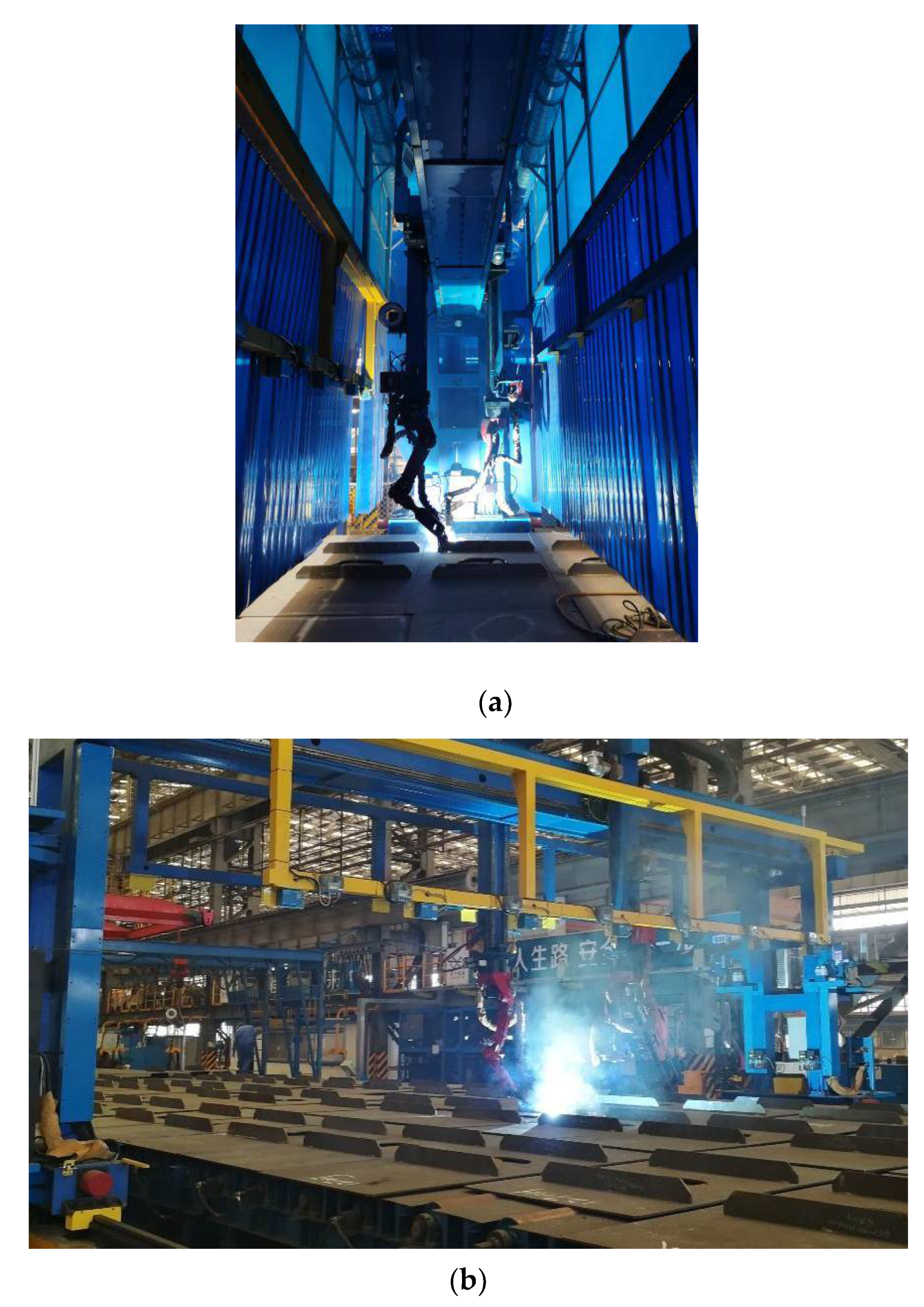
:1. Introduction
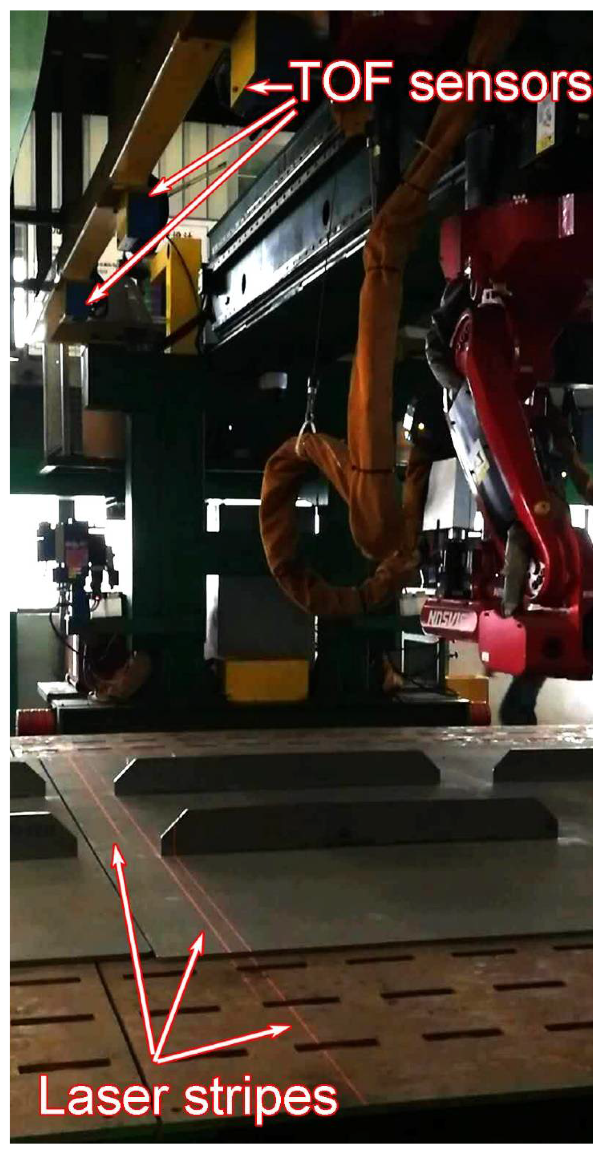
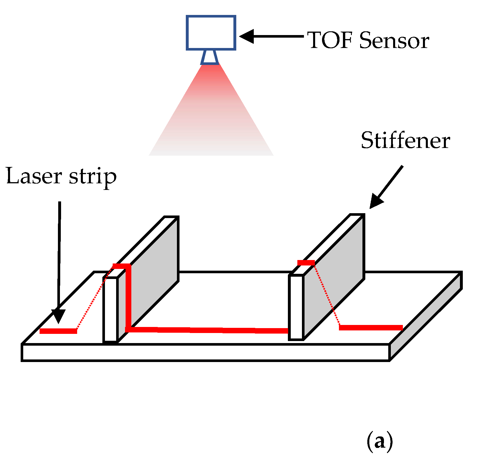
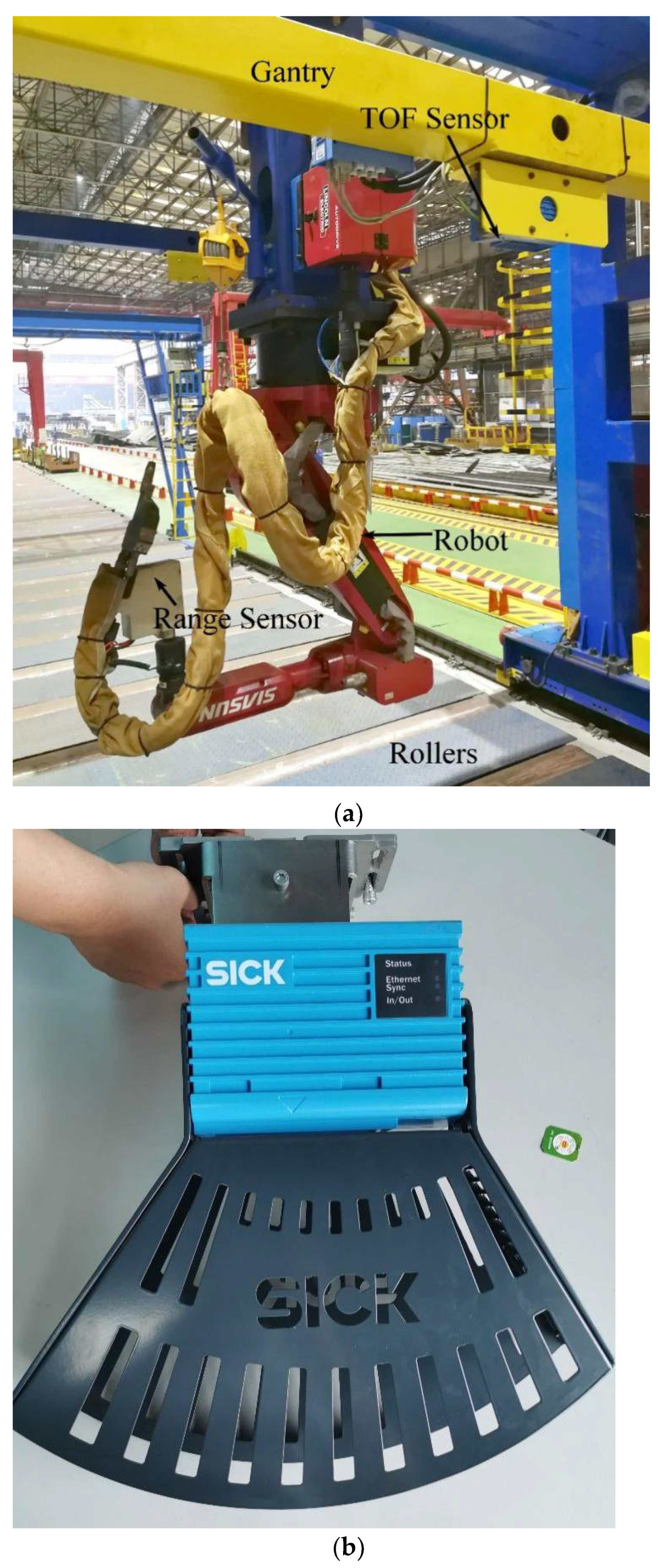
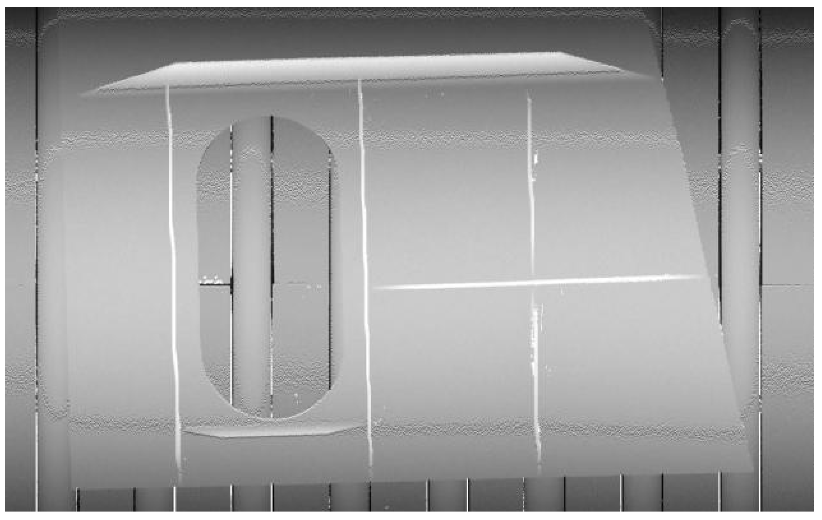
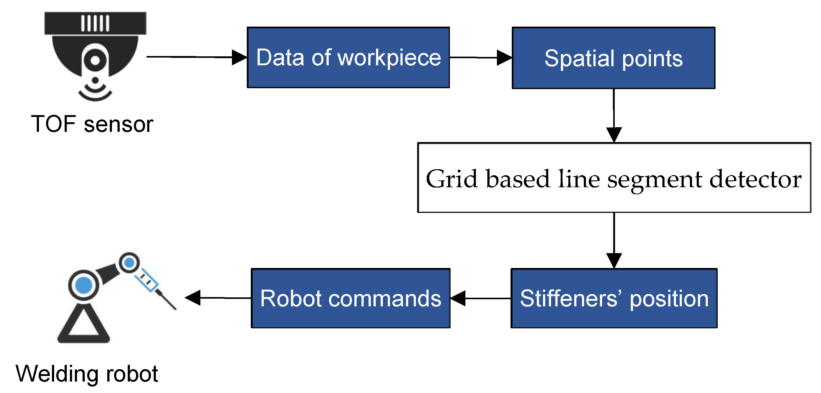
2. Hardware Implementation
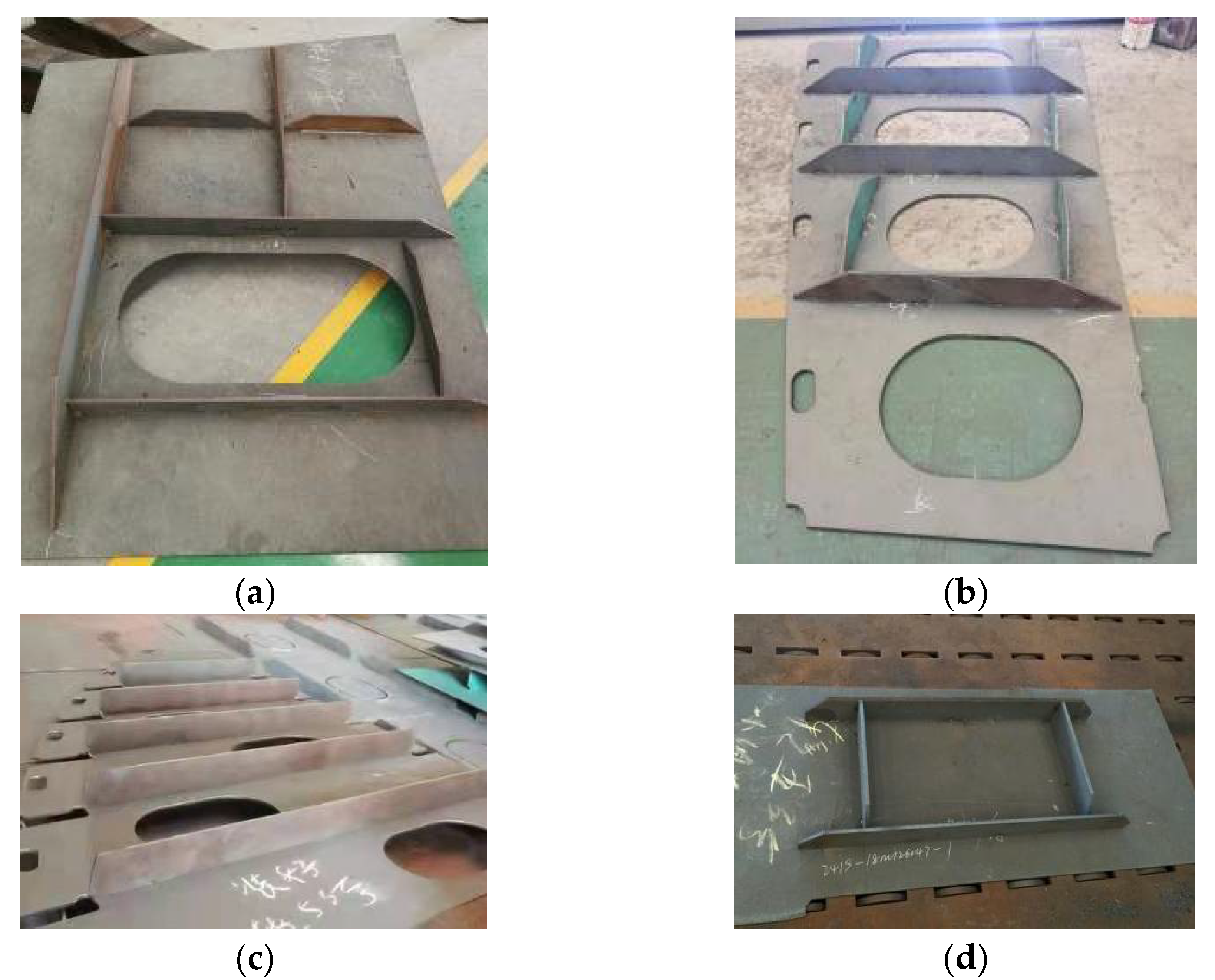
3. Reconstruction of Small Assembly
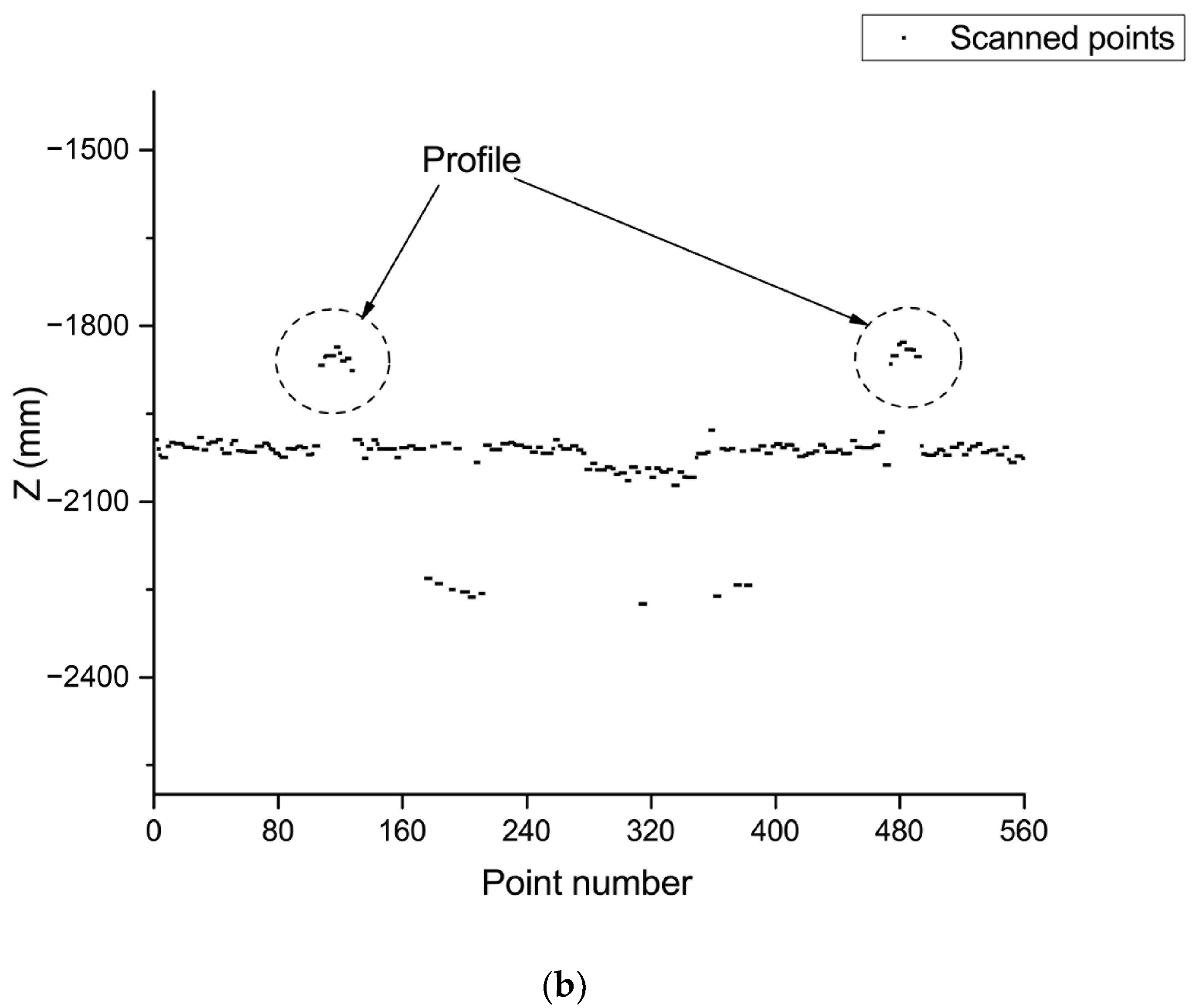
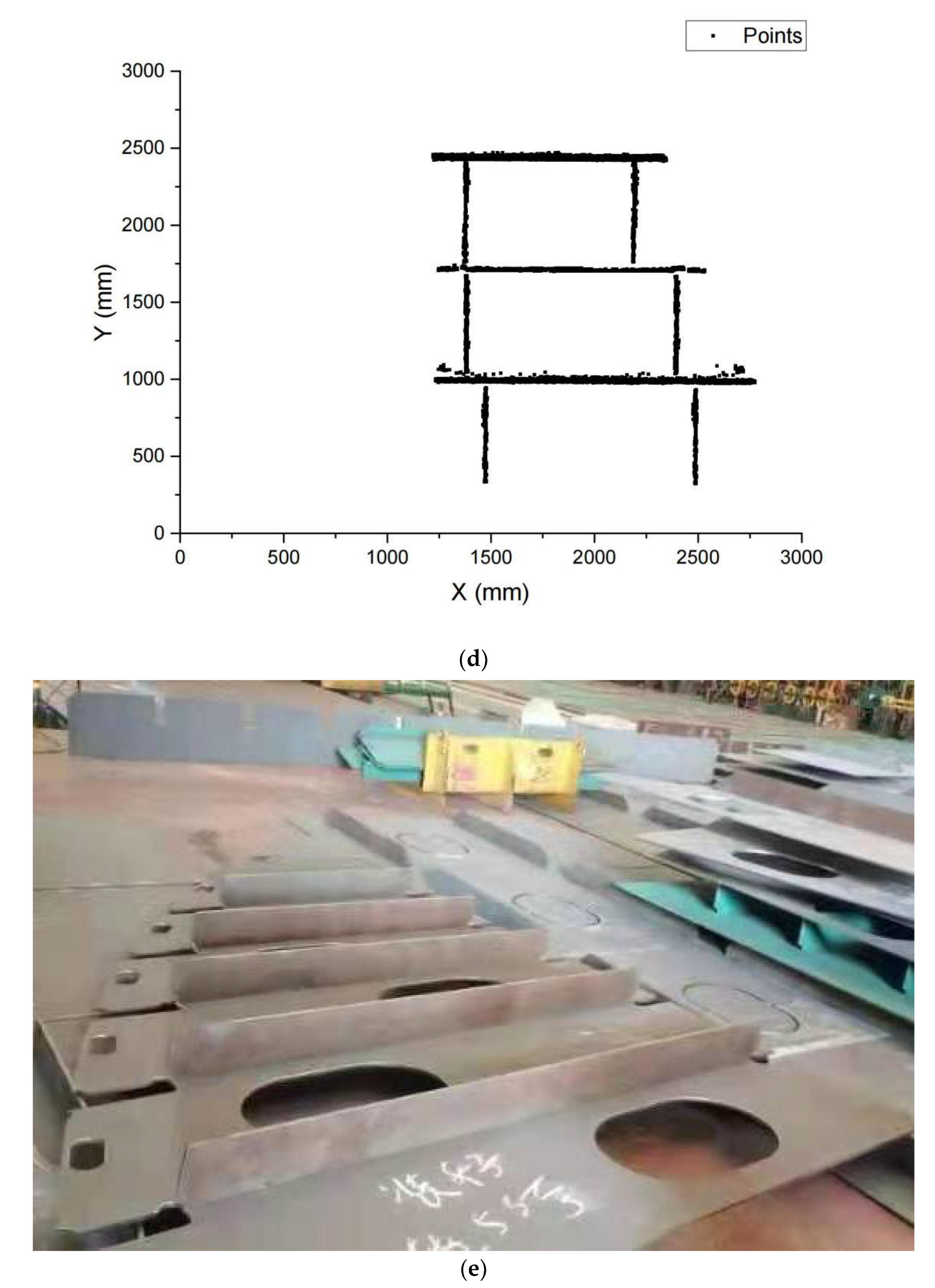
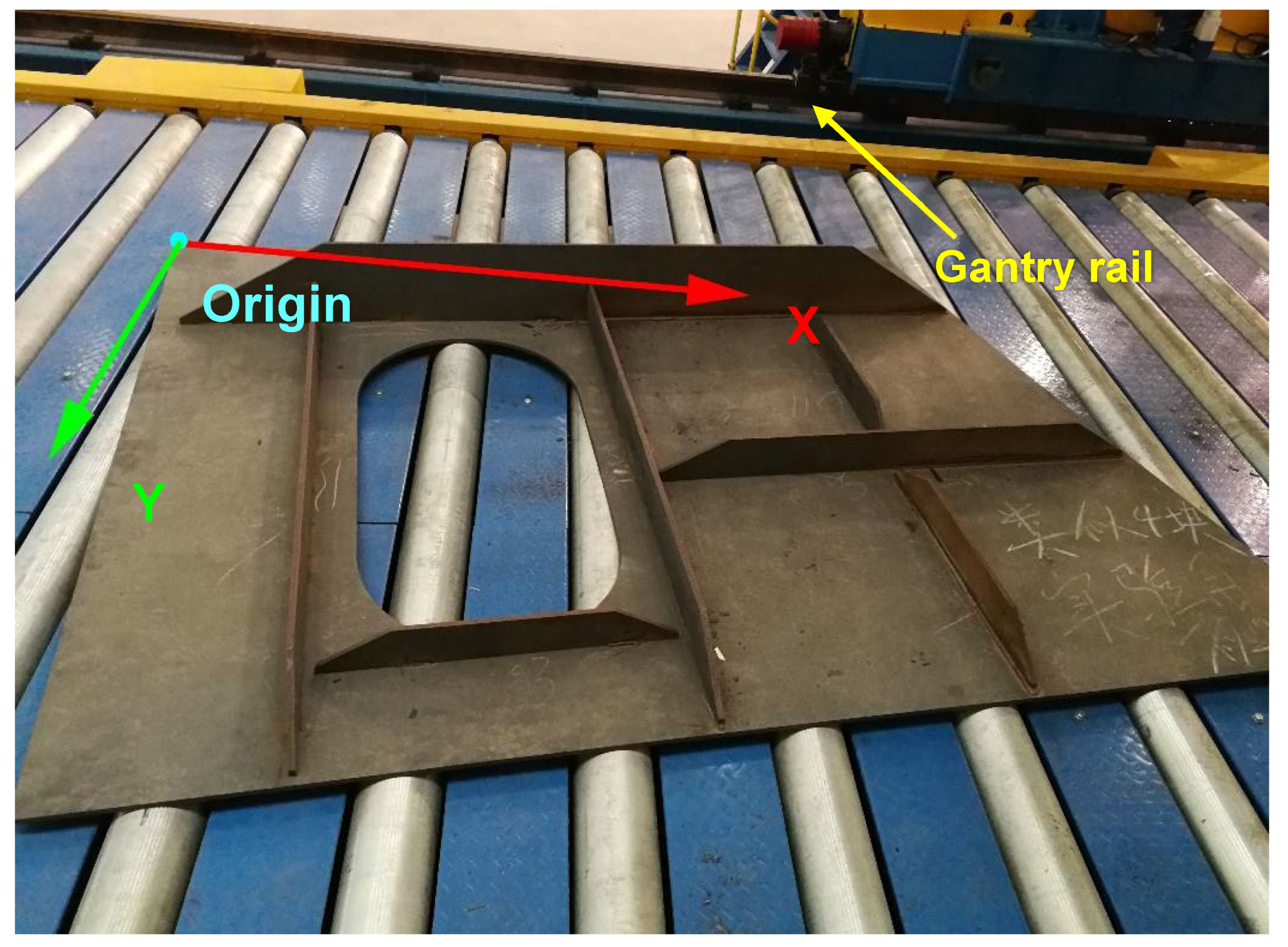
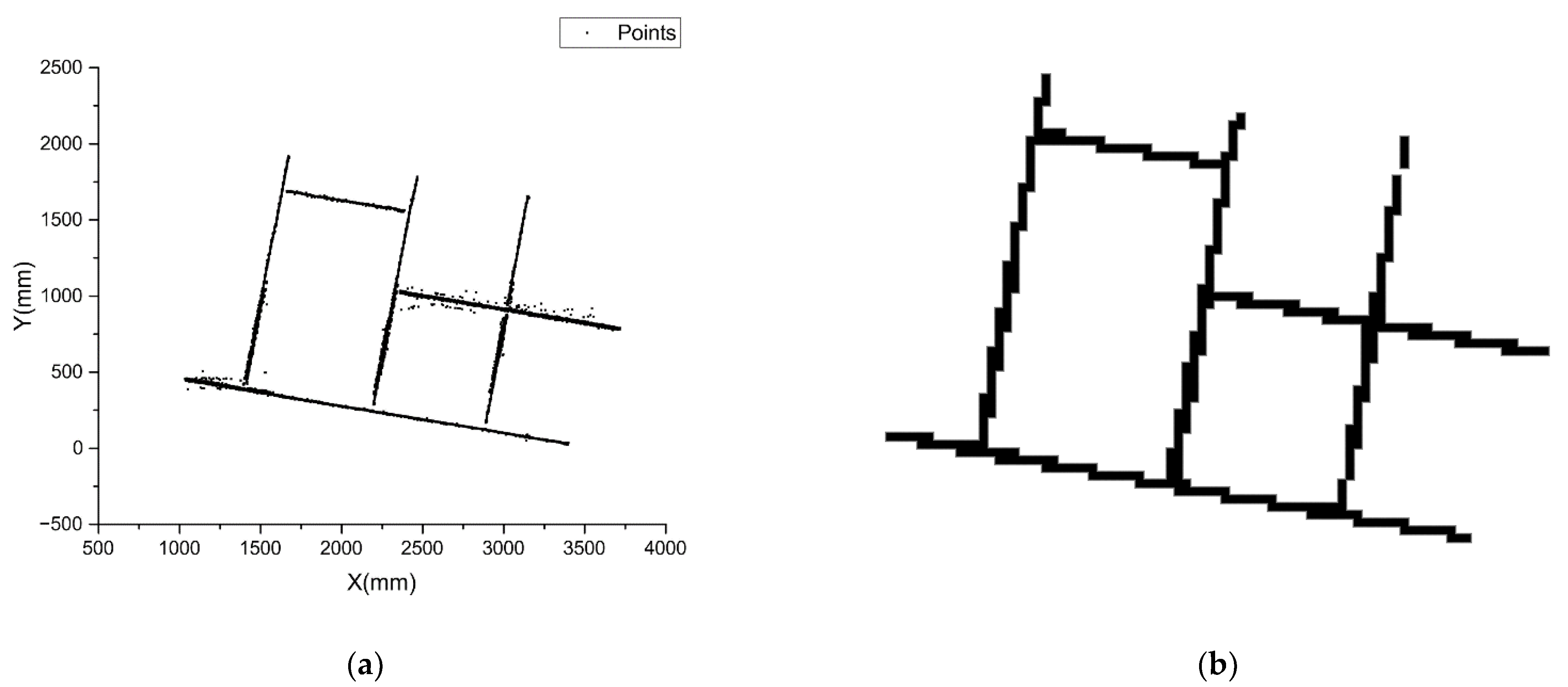
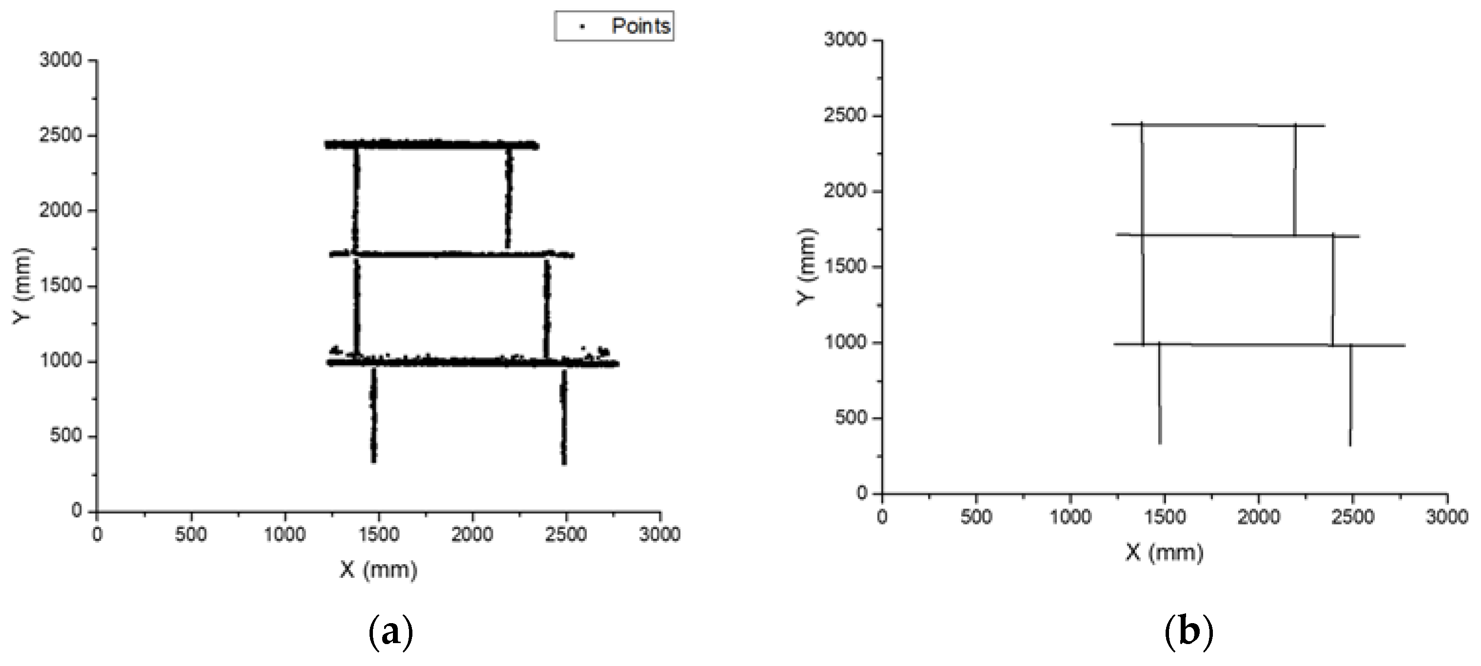
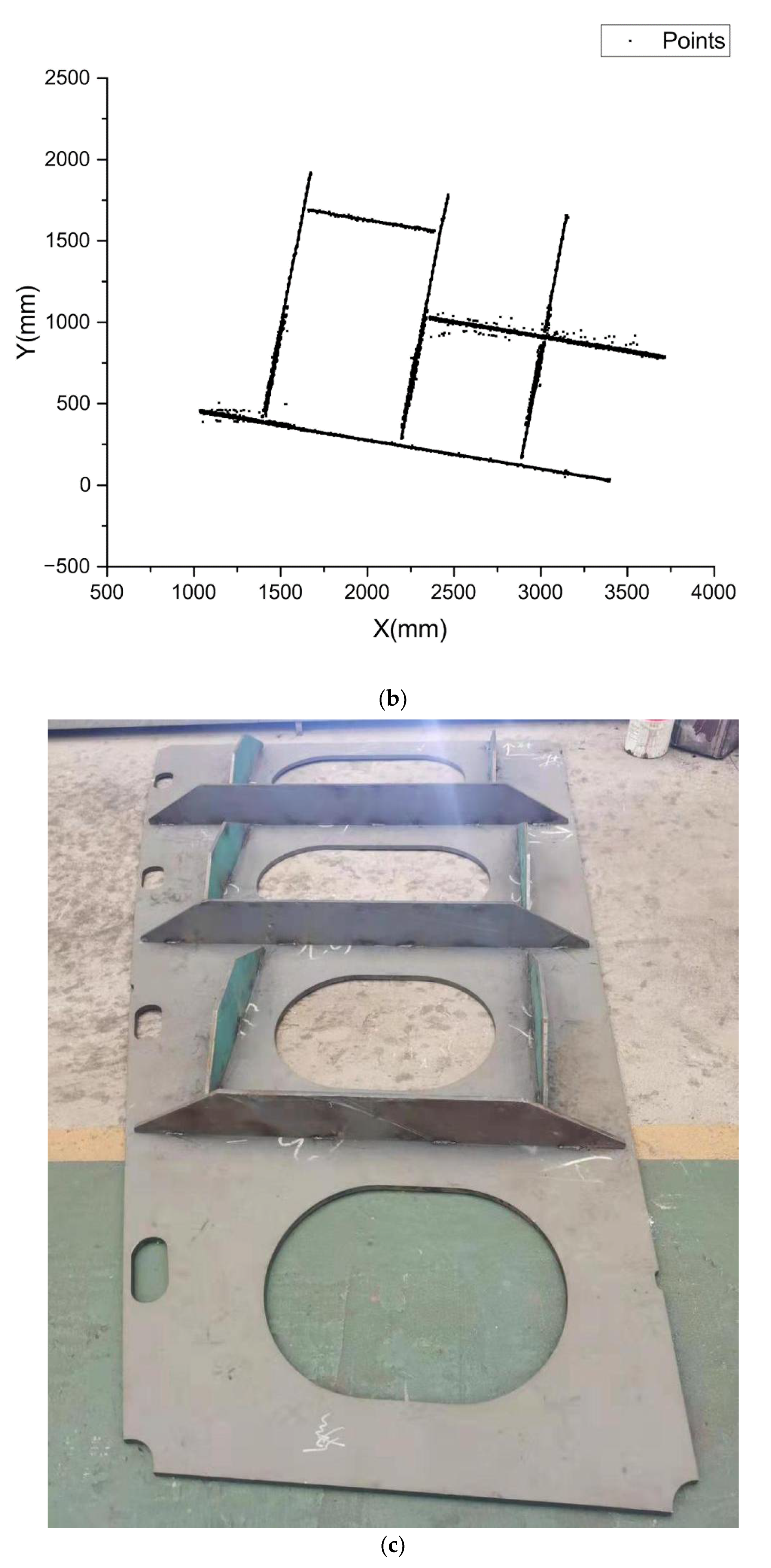
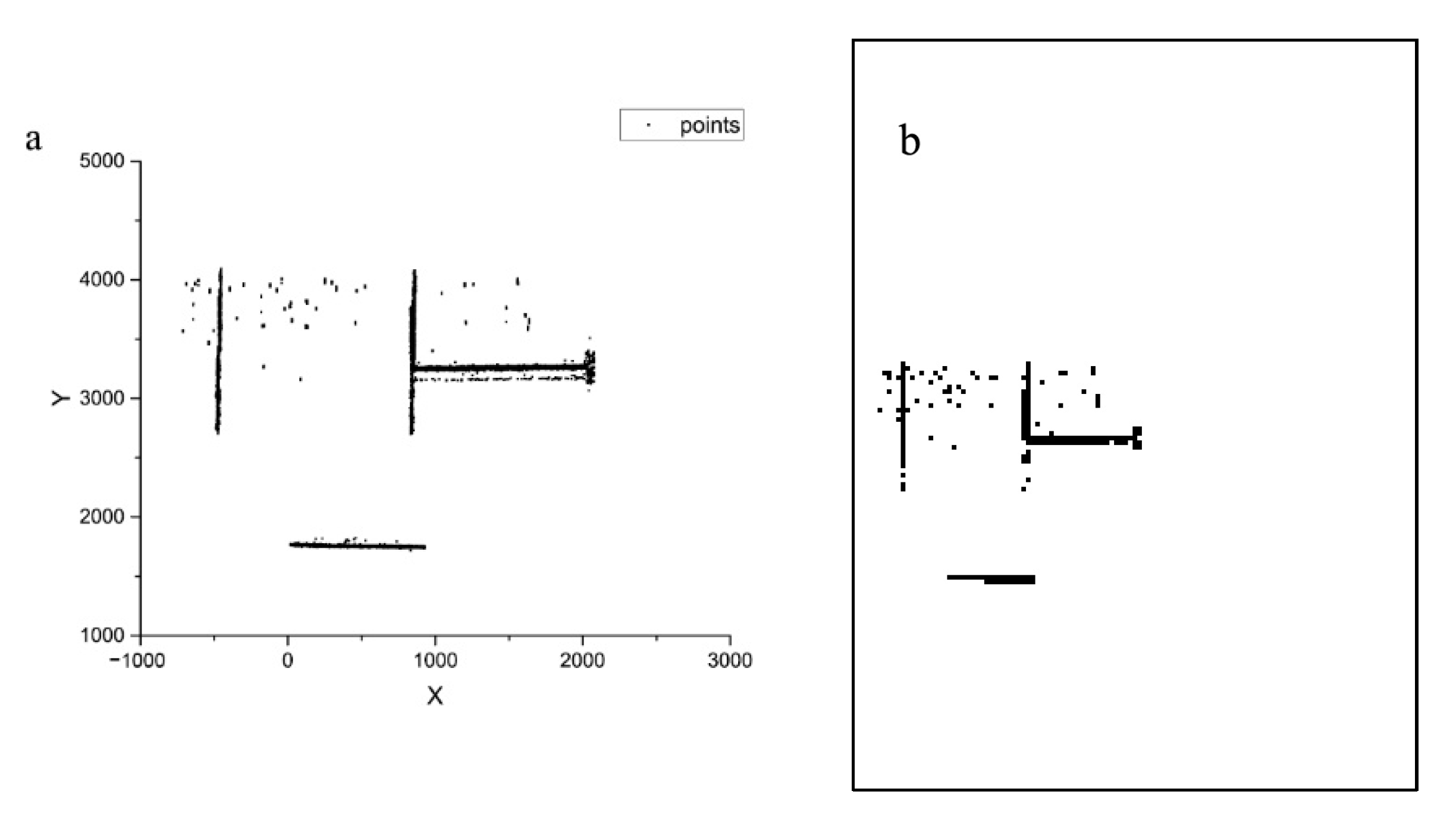
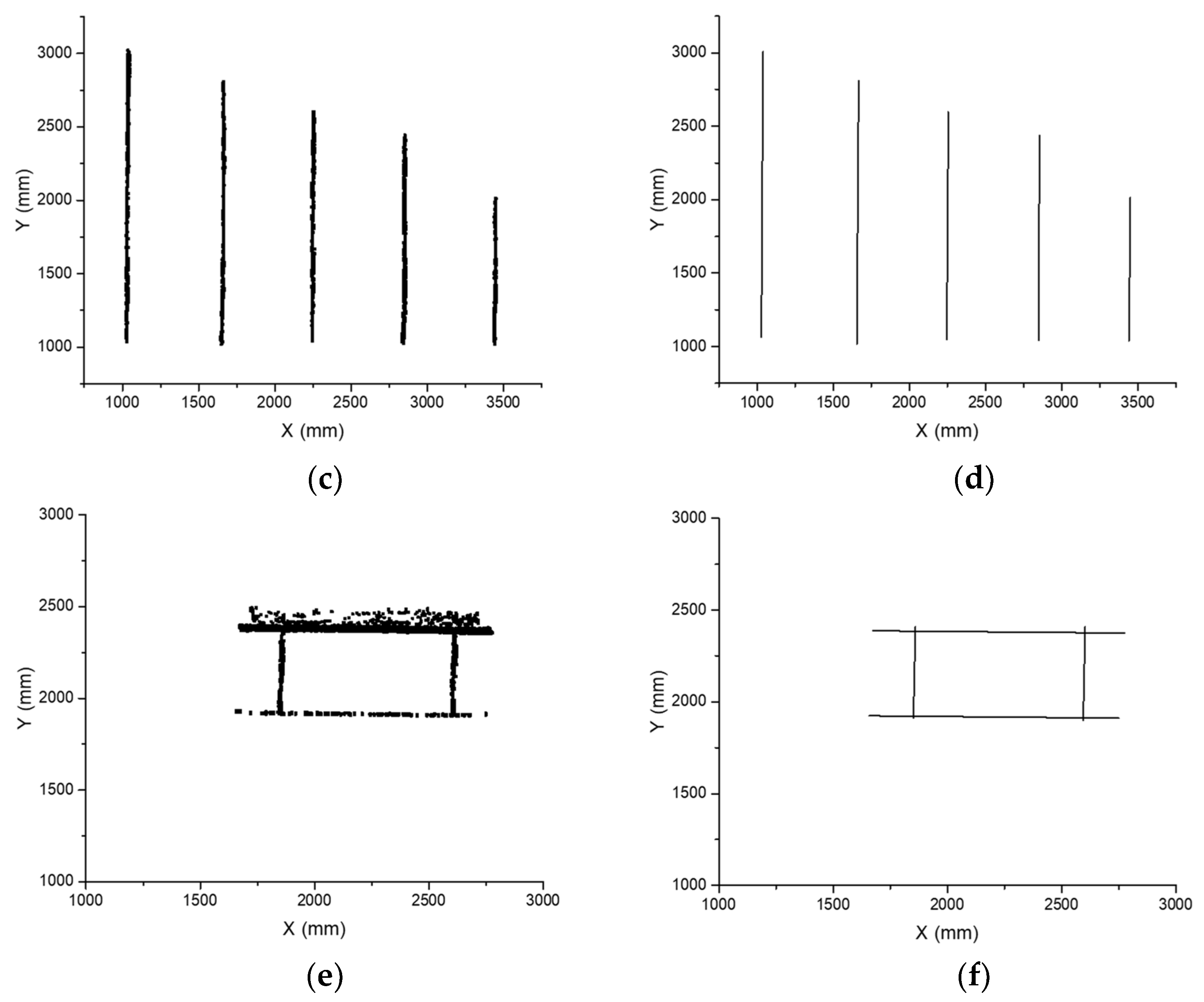
3.1. Spatial Points of Stiffeners
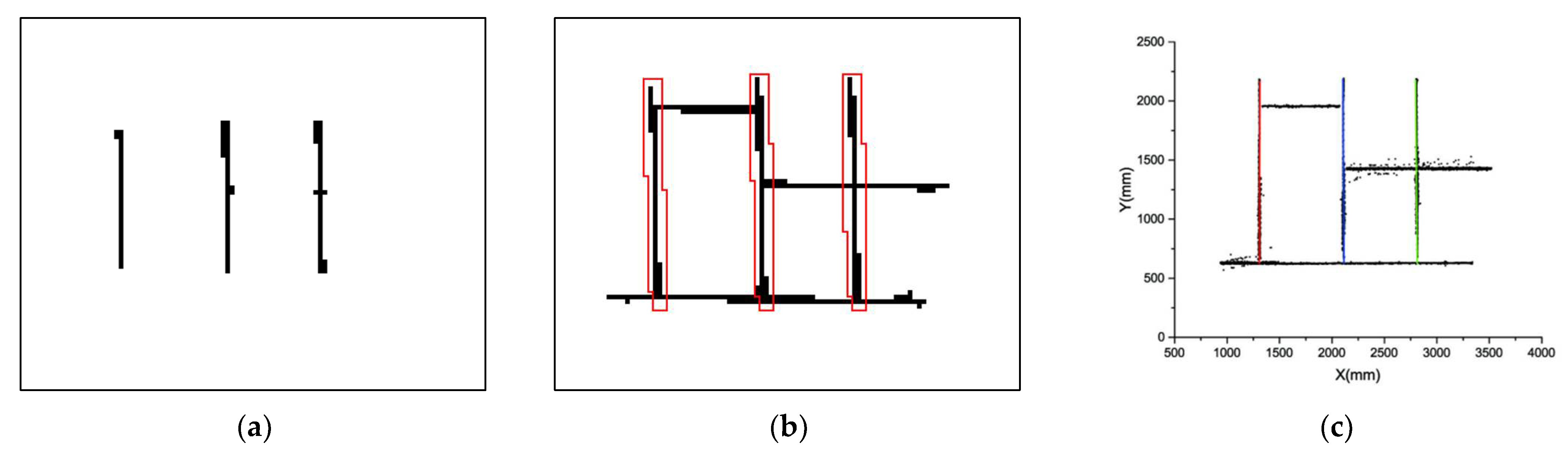
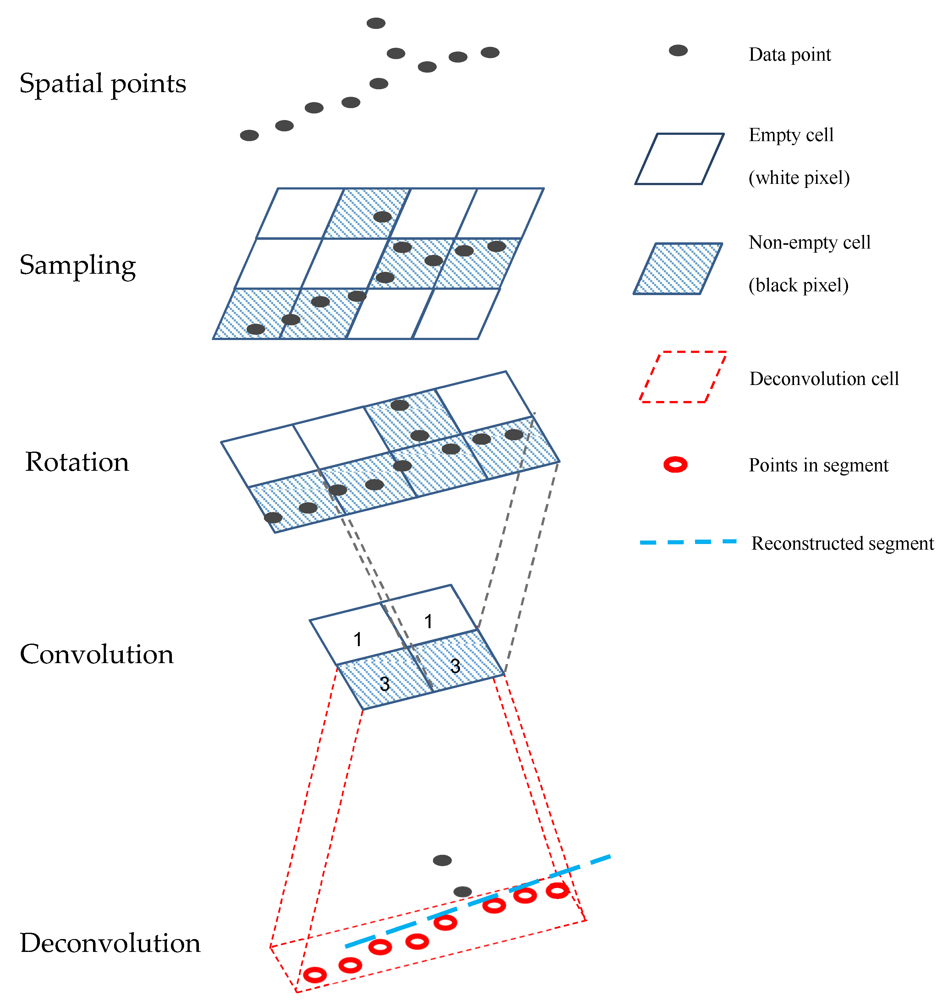
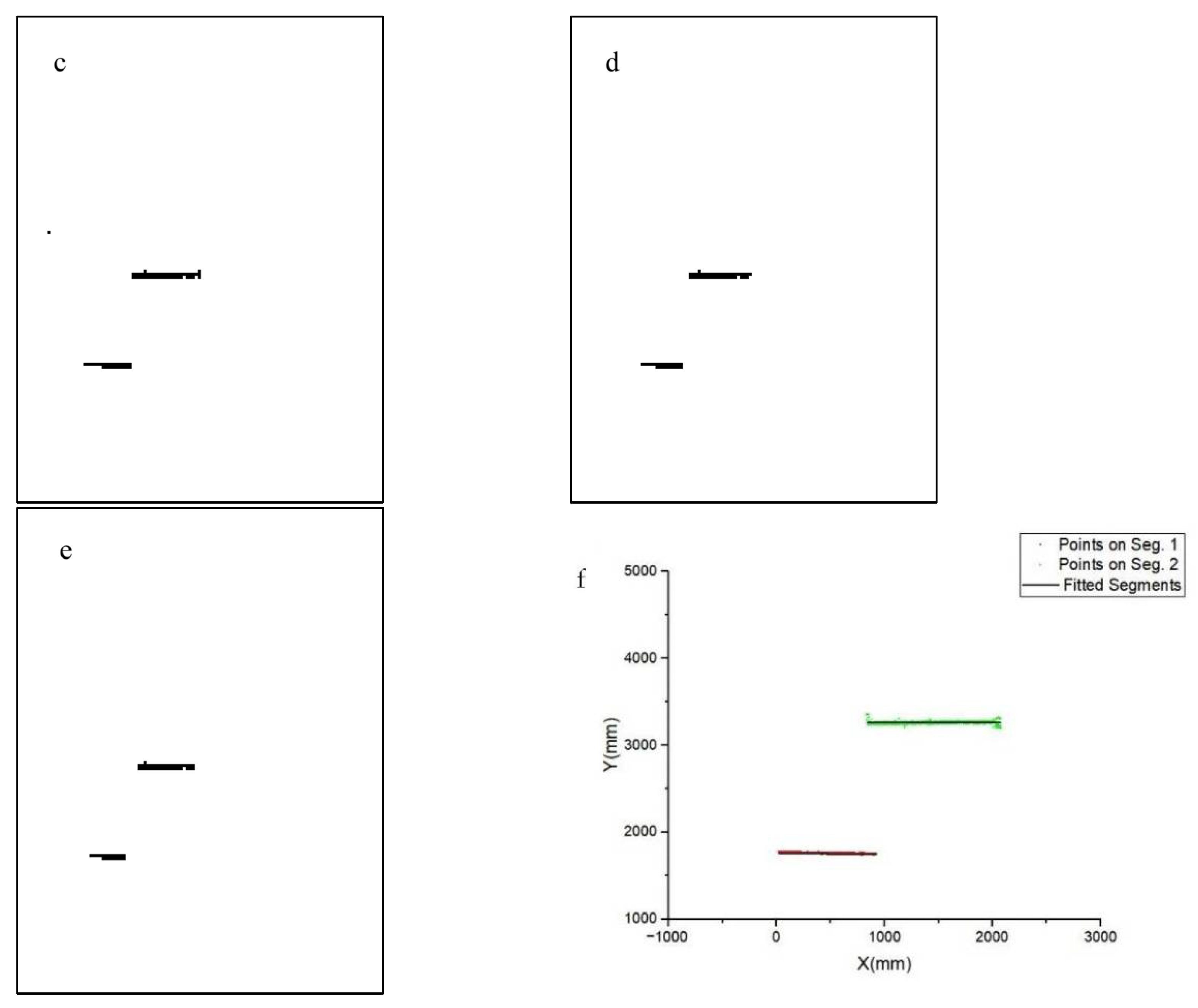
3.2. Grid-Based Line Segment Detector
- Move kernel’s center to a black pixel (i,j), i is the row index, j is the column index
- sum = 0;
- l = j − n;
- Check pixels at (i − 1,l), (i,l) and (i + 1,l), increase sum by 1 if any of these pixels is black;
- Increase l by 1;
- Repeat 3. until l = j + n;
- Convolution output at pixel g(i,j) = 1 if sum is not less than 2n, or g(i,j) = 0;
- Repeat 1. until all nonzero entries are convoluted.
4. Results and Verification
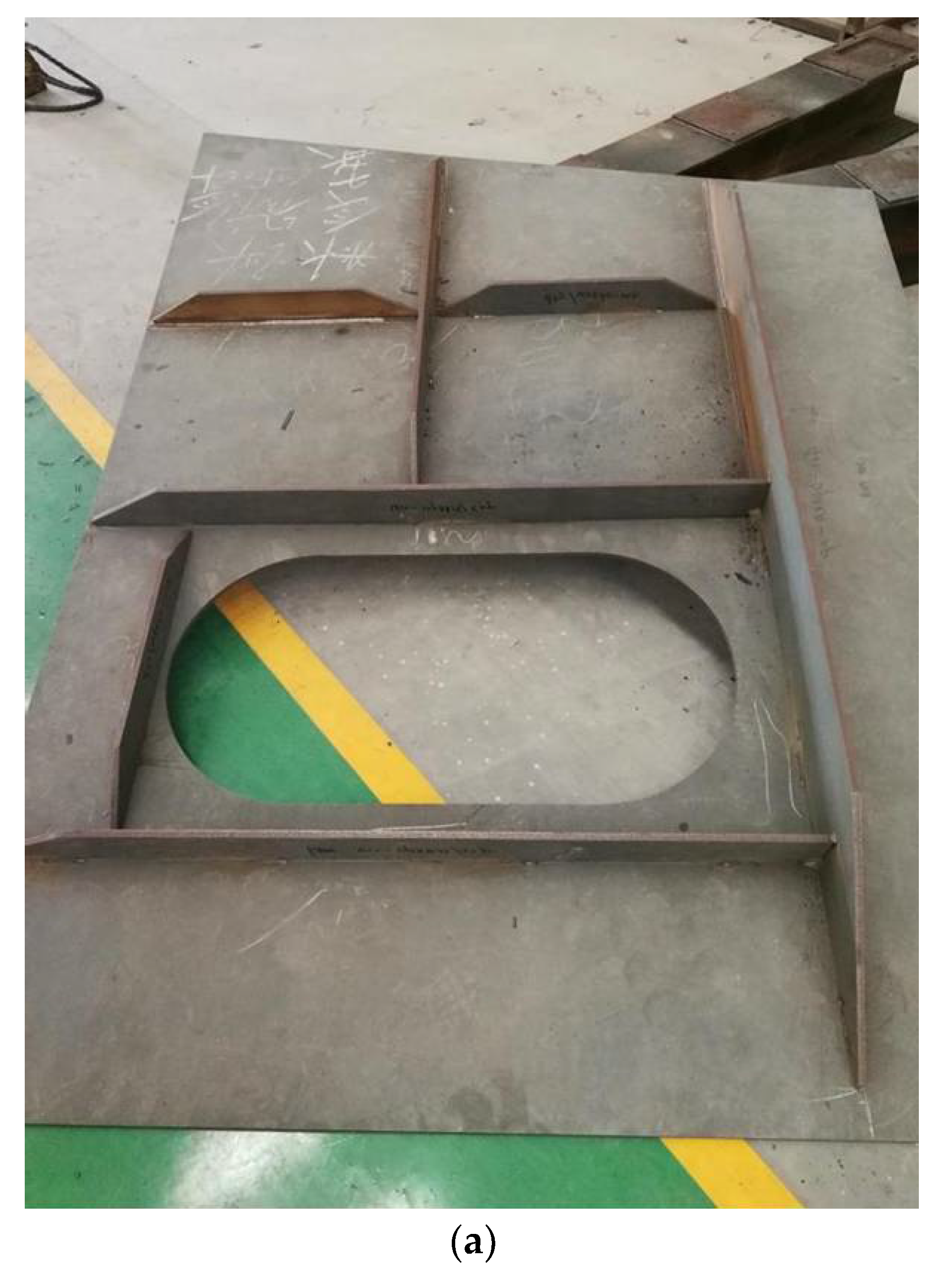
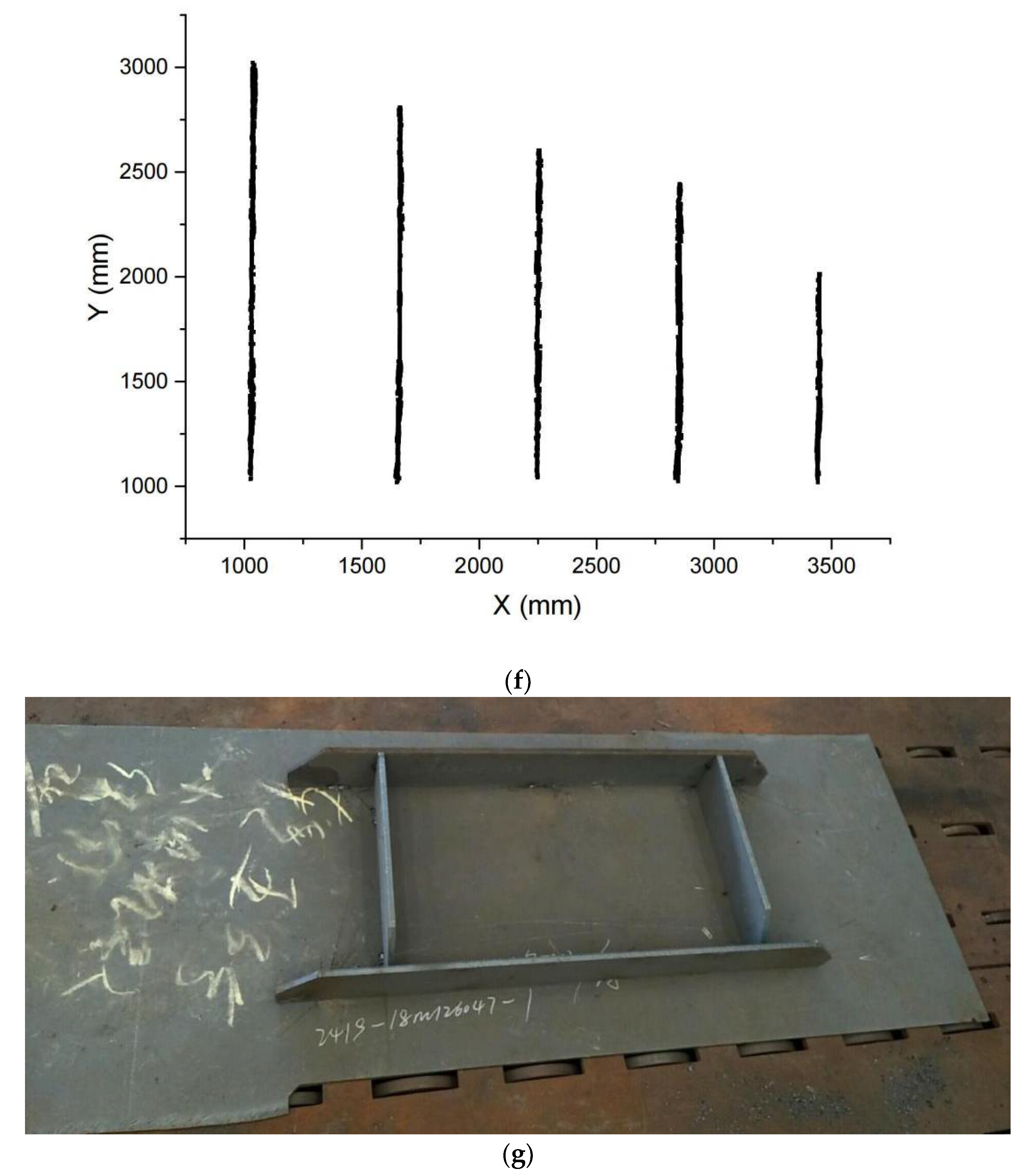
5. Application
6. Conclusions
- (1)
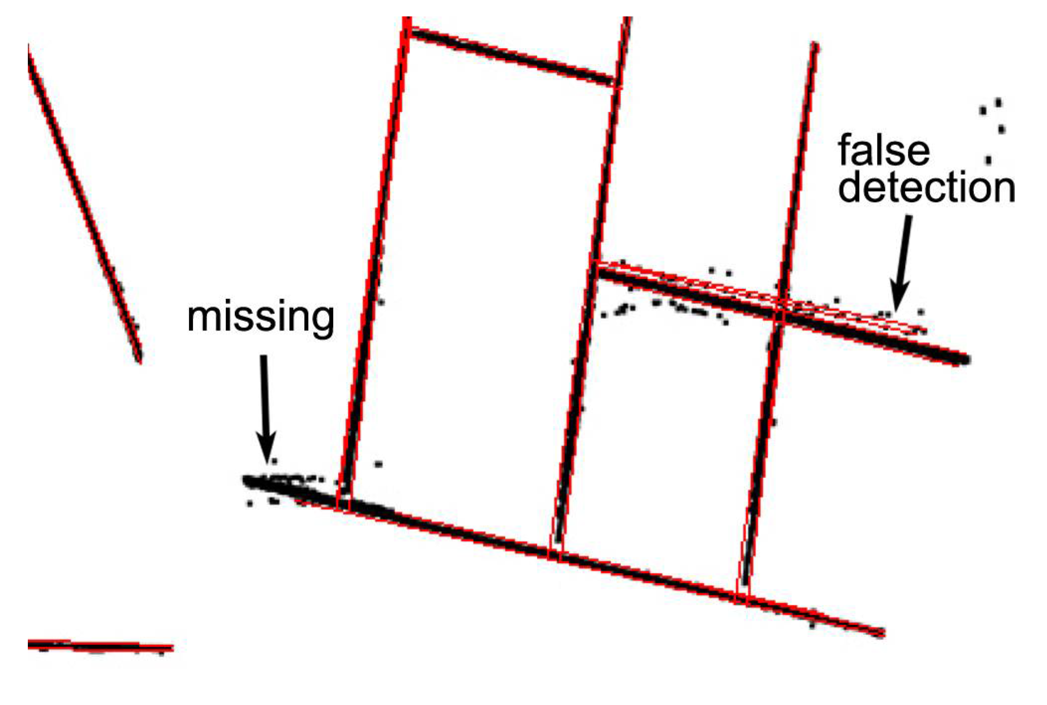
- The method presented in this paper demonstrated good robustness. It successfully clustered the points of stiffeners with complicated structures, despite the interference of noise. The robustness is a great advantage for industrial applications.
- (2)
- This algorithm was verified under manufacturing conditions and exhibited accuracy and robustness. Based on this work, intelligent ship small assembly lines were implemented and put into production in shipyards.
Author Contributions
Funding
Institutional Review Board Statement
Informed Consent Statement
Data Availability Statement
Conflicts of Interest
References
- Rooks, B. Robot Welding in Shipbuilding. Ind. Robot 1997, 24, 413–417. [Google Scholar] [CrossRef]
- Lee, D. Robots in the shipbuilding industry. Robot CIM Int. Manuf. 2014, 30, 442–450. [Google Scholar] [CrossRef]
- Lee, D.; Ku, N.; Kim, T.; Kim, J.; Lee, K.; Son, Y. Development and application of an intelligent welding robot system for shipbuilding. Robot CIM Int. Manuf. 2011, 27, 377–388. [Google Scholar] [CrossRef]
- Kam, B.; Jeon, Y.; Kim, S. Motion control of two wheeled welding mobile robot with seam tracking sensor. In Proceedings of the ISIE 2001—2001 IEEE International Symposium on Industrial Electronics Proceedings (Cat. No. 01TH8570); IEEE: Piscataway, NJ, USA, 2001; Volume 2, pp. 851–856. [Google Scholar] [CrossRef]
- Lee, J.; Kim, J.; Kim, J.; Park, J. Development of carriage-type welding Robot for double hull assembly line in shipbuilding. IFAC Proc. Vol. 2008, 41, 4310–4311. [Google Scholar] [CrossRef] [Green Version]
- Bedaka, A.; Vidal, J.; Lin, C. Automatic robot path integration using three-dimensional vision and offline programming. Int. J. Adv. Manuf. Technol. 2019, 102, 1935–1950. [Google Scholar] [CrossRef]
- Ferreira, L.; Figueira, Y.; Iglesias, I.; Souto, M. Offline CAD-based Robot Programming and Welding Parametrization of a Flexible and Adaptive Robotic Cell Using Enriched CAD/CAM System for Shipbuilding. Procedia Manuf. 2017, 11, 215–223. [Google Scholar] [CrossRef]
- Kang, S.; Youn, H.; Kim, D.; Kim, K.; Lee, S.; Kim, S. Development of multi welding robot system for sub assembly in shipbuilding. IFAC Proc. Vol. 2008, 41, 5273–5278. [Google Scholar] [CrossRef] [Green Version]
- Alexander, Z. Programming of Welding Robots in Shipbuilding. Procedia CIRP 2021, 99, 478–483. [Google Scholar] [CrossRef]
- Muhammad, J.; Altun, H.; Abo-Serie, E. Welding seam profiling techniques based on active vision sensing for intelligent robotic welding. Int. J. Adv. Manuf. Technol. 2016, 88, 127–145. [Google Scholar] [CrossRef]
- Chen, X.; Yu, J. Acquisition and optimization of weld trajectory and pose information for robot welding of spatial corrugated web sheet based on laser sensing. Int. J. Adv. Manuf. Technol. 2018, 96, 3033–3041. [Google Scholar] [CrossRef]
- Zhou, L.; Lin, T.; Chen, S. Autonomous Acquisition of Seam Coordinates for Arc Welding Robot Based on Visual Servoing. J. Intell. Robot Syst. 2006, 47, 239–255. [Google Scholar] [CrossRef]
- Chen, S.; Chen, X.; Qiu, T. Acquisition of Weld Seam Dimensional Position Information for Arc Welding Robot Based on Vision Computing. J. Intell. Robot Syst. 2005, 43, 77–97. [Google Scholar] [CrossRef]
- He, Y.; Chen, Y.; Xu, Y. Autonomous Detection of Weld Seam Profiles via a Model of Saliency-Based Visual Attention for Robotic Arc Welding. J. Intell. Robot Syst. 2016, 81, 395–406. [Google Scholar] [CrossRef]
- Lü, X.; Zhang, K.; Wu, Y. The seam position detection and tracking for the mobile welding robot. Int. J. Adv. Manuf. Technol. 2017, 88, 2201–2210. [Google Scholar] [CrossRef]
- Moon, H.; Kim, Y.; Beattie, R. Multi sensor data fusion for improving performance and reliability of fully automatic welding system. Int. J. Adv. Manuf. Technol. 2006, 28, 286–293. [Google Scholar] [CrossRef]
- Gu, W.; Xiong, Z.; Wan, W. Autonomous seam acquisition and tracking system for multi-pass welding based on vision sensor. Int. J. Adv. Manuf. Technol. 2013, 69, 451–460. [Google Scholar] [CrossRef]
- Tsai, M.; Lee, H.; Ann, N. Machine Vision Based Path Planning for a Robotic Golf Club Head Welding System. Robot CIM Int. Manuf. 2011, 27, 843–849. [Google Scholar] [CrossRef]
- Zhang, K.; Yan, M. 3D Reconstruction of Complex Spatial Weld Seam for Autonomous Welding by Laser Structured Light Scanning. J. Manuf. Proc. 2019, 39, 200–207. [Google Scholar] [CrossRef]
- Dong, S.; Liu, J.; Liu, Y.; Zeng, L.; Xu, C.; Zhou, T. Clustering based on grid and local density with priority-based expansion for multi-density data. Inform. Sci. 2018, 468, 103–116. [Google Scholar] [CrossRef]
- Yue, S.; Wei, M.; Wang, J.; Wang, H. A general grid-clustering approach. Pattern Recogn. Lett. 2008, 29, 1372–1384. [Google Scholar] [CrossRef]
- Wang, W.; Yang, J.; Richard, M. STING: A Statistical Information Grid Approach to Spatial Data Mining. In Proceedings of the 23rd International Conference on Very Large Data Bases (VLDB ’97); Morgan Kaufmann Publishers Inc.: San Francisco, CA, USA, 1997; pp. 186–195. [Google Scholar]
- Sheikholeslami, G.; Chatterjee, S.; Zhang, A. WaveCluster: A Multi-Resolution Clustering Approach for Very Large Spatial Databases. In Proceedings of the 24rd International Conference on Very Large Data Bases (VLDB ’98); Morgan Kaufmann Publishers Inc.: San Francisco, CA, USA, 1998; pp. 428–439. [Google Scholar]
- Agrawal, R.; Gehrke, J.; Gunopulos, D.; Raghavan, P. Automatic subspace clustering of high dimensional data for data mining applications. In Proceedings of the 1998 ACM SIGMOD International Conference on Management of Data (SIGMOD ’98); Association for Computing Machinery: New York, NY, USA, 1998; pp. 94–105. [Google Scholar] [CrossRef] [Green Version]


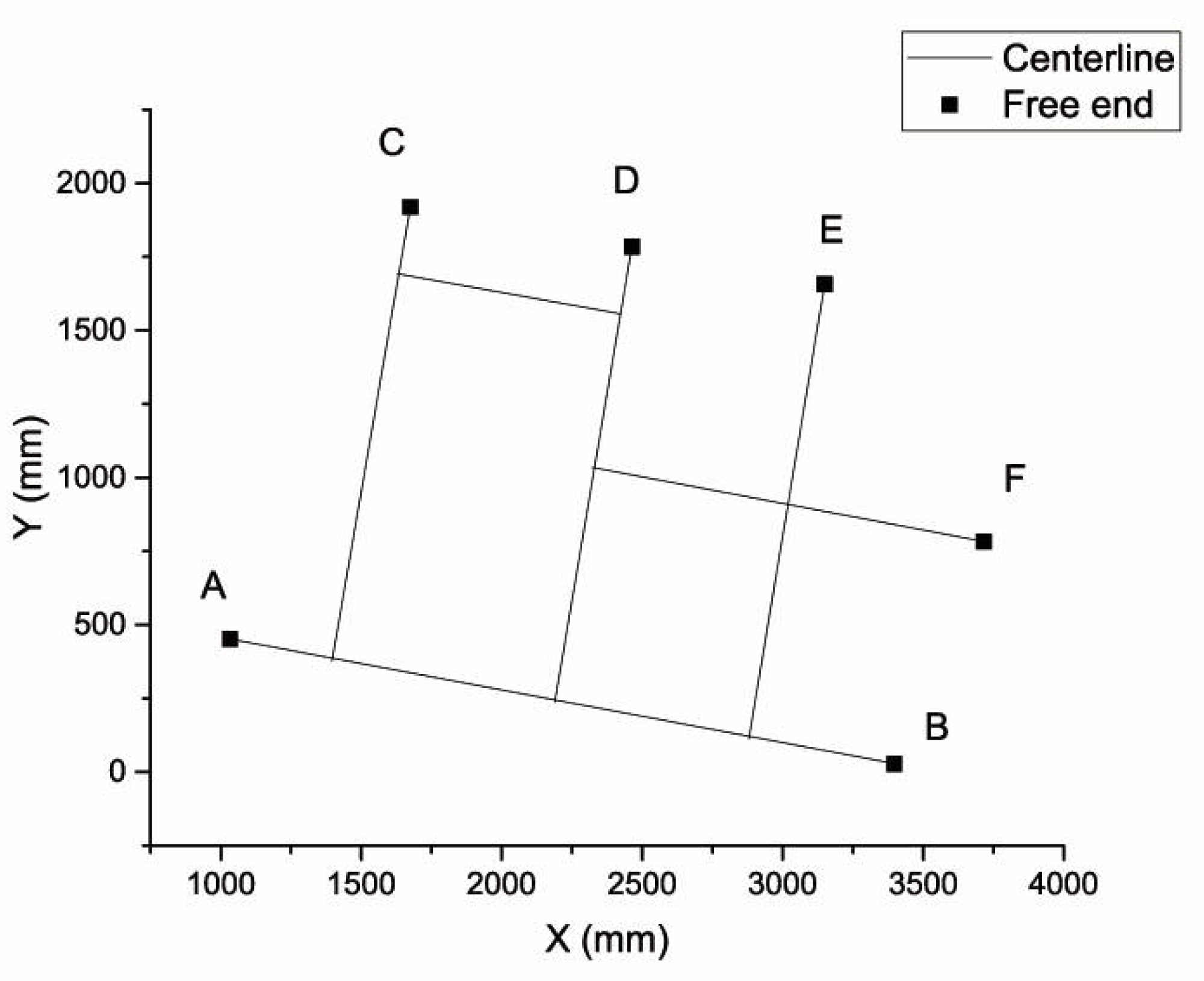
| Free End | X (mm) | Y (mm) |
|---|---|---|
| A | 1043 | 452 |
| B | 3431 | 28 |
| C | 1691 | 1919 |
| D | 2489 | 1784 |
| E | 3181 | 1656 |
| F | 3754 | 783 |
| Free End | Measured Position (x, y) | Reconstructed Position (x, y) | Distance (mm) |
|---|---|---|---|
| A | (1032, 426) | (1043, 452) | 28.2 |
| B | (3410, 25) | (3431, 28) | 21.2 |
| C | (1682, 1910) | (1691, 1919) | 12.7 |
| D | (2483, 1773) | (2489, 1784) | 10.8 |
| E | (3177, 1650) | (3181, 1656) | 7.2 |
| F | (3725, 798) | (3754, 783) | 32.6 |
Publisher’s Note: MDPI stays neutral with regard to jurisdictional claims in published maps and institutional affiliations. |
© 2021 by the authors. Licensee MDPI, Basel, Switzerland. This article is an open access article distributed under the terms and conditions of the Creative Commons Attribution (CC BY) license (https://creativecommons.org/licenses/by/4.0/).
Share and Cite
Ding, J.; Ni, C. Gird Based Line Segment Detector and Application: Vision System for Autonomous Ship Small Assembly Line. J. Mar. Sci. Eng. 2021, 9, 1313. https://doi.org/10.3390/jmse9111313
Ding J, Ni C. Gird Based Line Segment Detector and Application: Vision System for Autonomous Ship Small Assembly Line. Journal of Marine Science and Engineering. 2021; 9(11):1313. https://doi.org/10.3390/jmse9111313
Chicago/Turabian StyleDing, Jinhong, and Chongben Ni. 2021. "Gird Based Line Segment Detector and Application: Vision System for Autonomous Ship Small Assembly Line" Journal of Marine Science and Engineering 9, no. 11: 1313. https://doi.org/10.3390/jmse9111313
APA StyleDing, J., & Ni, C. (2021). Gird Based Line Segment Detector and Application: Vision System for Autonomous Ship Small Assembly Line. Journal of Marine Science and Engineering, 9(11), 1313. https://doi.org/10.3390/jmse9111313