1. Introduction
Ergonomic analysis, widely applied in physical therapy and sports training, provides a tool that achieves optimal performance while reducing the risk of human error or injury [
1]. Recently, ergonomic analysis has been required in various industrial fields, and in particular, the design of a more efficient and safe working environment has been emphasized from the workers’ perspective.
Several studies have shown that the introduction of ergonomics improves working conditions and reduces the number of work-related musculoskeletal disorders, which ultimately increases work productivity and reduces related costs [
2,
3,
4]. Consequently, ergonomic researchers perform workload assessments to determine the maximum workload level that does not violate the steady state when the cardiopulmonary function reaches a balanced state.
Workload generally refers to a measure of various stresses that affect a worker’s performance and perception [
5]. In human–machine systems, it is also used as a term to describe the cost of achieving work requirements. Industrial sites, where workloads are always present, should be designed to provide a certain level of workload that does not interfere with the capabilities and functions of workers such that the working site can be operated safely and efficiently [
6].
Workloads are generally divided into mental and physical aspects. As the automation of some processes in the industry progresses along with technological advancement, the worker’s physical activity is gradually decreasing. Nevertheless, there are cases where it is difficult to introduce automatic control owing to the nature of the processes. For this manual work, it is necessary to consider the physical workload resulting from working posture. Working posture refers to the posture or physical activity adopted by a worker performing a task. As working posture and associated movement are not only important mechanical variables but also load-determining factors, they must be considered for industrial safety [
7]. These variables are claimed to have a profound relationship with musculoskeletal diseases. Processes that require severe physical activity can affect the muscles of an individual if his or her working posture remains the same for a long time or is repeatedly performed [
8]. A variety of analytical tools have been developed to accurately assess workloads for working postures [
8,
9,
10,
11,
12,
13,
14,
15].
A typical example that accompanies manual labor is the welding task in the shipbuilding block assembly process. The shipbuilding industry is known to have a relatively high dependence on manpower owing to the demand for long welding lengths, various welding parts, and high welding quality compared to other industries. Welding in the hull block assembly is a critical process in which an enormous amount of time and cost are invested.
To overcome the weaknesses of this labor-intensive working environment, there is a trend of increasing welding automation facilities. Currently, most shipyards use welding robots in the flat block assembly process; however, this work is mainly limited to unit-assembly processes or filet welds between longitudinal structural members and panels. As the welding robot used in the assembly process moves only within a limited range of motion, it is difficult to apply the robot to the block of a grand-assembly stage, which generally has a narrow space owing to many outfitting parts and structural members. Therefore, in the later stages of the assembly process, many workers still weld manually.
Manual welding requires different types of working postures depending on the assembly tasks, which results in a difference in the man-hours of each block assembly. Large shipyards have also recognized the difference in man-hours depending on the welding positions. They analyze various causes or sources to predict an assembly man-hour similar to the actual value occurring at a site. Consequently, the welding factor, a quantitative value defined by shipyards to account for the level of welding influence, was developed and included in their man-hour calculation systems. As some confidential environmental features and work characteristics of each shipyard are clearly reflected, these welding factors are treated as confidential and are used only for internal purposes.
Academically, there have been attempts to link the relationship between ergonomic conditions, workloads, total action cost, and productivity in processes that involve human factors, such as manual welding [
16,
17,
18,
19,
20]. The welding work in the enclosed space of a ship was analyzed by Lowe et al. [
21]. They investigated the fatigue of seven upper-limb muscles caused by two types of welding processes, shielded metal arc welding and flux-core arc welding, by comparing the measurement results obtained by surface electromyography (sEMG). To evaluate the feasibility of an alternatively designed system, sEMG was used to measure and analyze the relevant muscle activity [
22]. A welding training method using the muscle activity measured by EMG as an index was proposed by Stone et al. [
23]. Singh and Singhal [
24] compared the workload between skilled and unskilled welders based on the rapid upper limb assessment (RULA) technique. Suman et al. [
25] collected data through the RULA, OWAS, and discomfort questionnaire, and then performed a postural stress analysis of welders based on finite element analysis, comparing the results before and after the improvement of the working environment. The abovementioned studies aimed to show, through workload evaluation, that the uncomfortable working posture that occurs in manual welding influences work-related musculoskeletal disorders. Therefore, the results are considerably different from quantitative workload evaluation, which is a kind of welding factor pursued in this study.
Welding factors simply imply that the welding difficulty can eventually have a direct influence on man-hours. As these factors are dependent on accumulated experience or observation, it is not easy to check the validity or reliability of the results. In the case of small- and medium-sized shipyards or subcontractors, it is even more difficult to initiate the establishment of a database on welding factors, and consequently, the accurate prediction of man-hours cannot be expected. The fact that the welding position determines the man-hours that affect the production efficiency at assembly shops cannot be gainsaid, not to mention a safe working environment. Nevertheless, research linking the welding position and the resulting efficiency is still insufficient.
This study proposed a method of quantitatively deriving a physical welding factor based on the workload evaluation, aiming at the manual welding position in the shipbuilding block assembly process. The numerical factor derived in this study explains the difficulty of a welding work, based on the reasonable assumption that the physical workload caused by the working posture has a decisive effect on the man-hour calculation system, similar to the role of welding factors. The physical welding factor was obtained via performing physical workload evaluation by sEMG and quantifying the evaluated workload.
In
Section 2, we introduce a method for classifying the manual welding positions in the block assembly based on an analysis of the current welding practices as well as the results of interviews with welding workers on-site. Reclassified welding positions are essential to deriving the physical welding factors.
Section 3 describes the process of measuring sEMG as a method for evaluating the workload.
Section 4 introduces the method to quantify the physical welding factors, as a way to explain the degree of difficulty for manual welding positions. The obtained results are compared with those of the simulation analysis using a musculoskeletal system and welding factors of a shipyard to prove the usability of the proposed method.
2. Subjective Evaluation of Welding Position
It is common to select body posture as the main variable for evaluating workload. Prior to the selection of the proper variables, the definition of the working posture must be determined. In this section, the working postures involved in the welding work are analyzed. Working posture generally depends on the characteristics of the work, size of the target objects, and job site. Welding often requires an unfavorable posture owing to high temperatures, obstruction of vision, or poor working conditions. Based on the industrial standard postures specified for welding, a new classification of welding positions occurring in the shipbuilding industry was promoted. The body posture linked to the established welding work was identified and classified, focusing on the muscles and body joints of the welders. The classified body posture was used as a basic guideline for the measurement of muscle activity in the following section.
2.1. Industrial Standard of Welding Positions
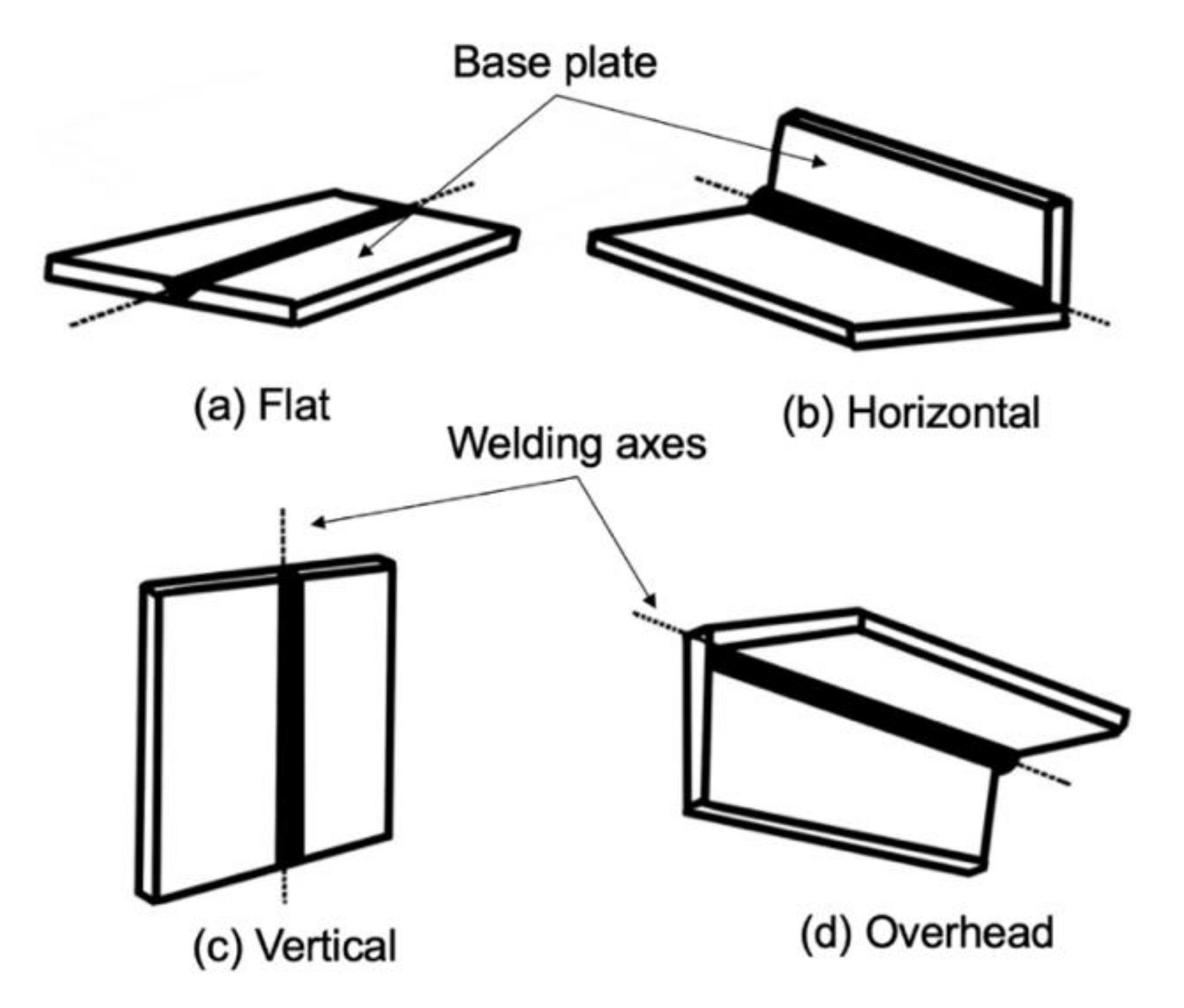
Industrial standards for welding positions have been proposed internationally. The purpose of establishing a standard was to increase the reliability of weld quality. The contents of the standard are continuously updated by prestigious societies such as the American Welding Society (AWS), International Organization for Standardization (ISO), and the American Society of Mechanical Engineering (ASME). The welding standard positions currently designated by the industry are classified into four types, as described in
Table 1, and the relationship between the base metal and the welding axis used for the classification is shown in
Figure 1.
The classified welding positions are mainly defined by the positions where the welding axis and base plate are placed. This classification is solely a relational arrangement based on the position of the objects; it does not consider factors such as the position or angle of the body joints of the welder. Thus, this classification does not provide enough information to analyze the effect of posture on the body when working in a special welding position.
In particular, because the scale of objects assembled in shipbuilding shops is generally large, the movement of the welder inevitably increases. This requires a working posture different from that of a general field; thus, more-diverse welding positions need to be considered.
2.2. Reclassification of New Welding Positions via Working Posture Information
As the classification of industrial standard welding positions is performed focusing on the common welding positions in industry, it cannot sufficiently reflect the characteristics of a specialized working environment, such as the block assembly process of shipyards. A new classification is necessary to consider these special situations.
2.2.1. Analysis of Working Posture in Welding
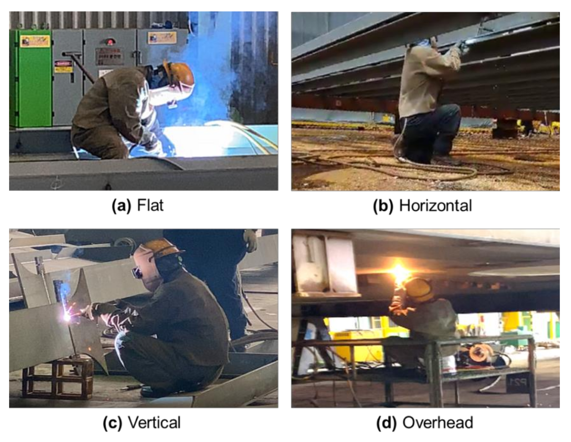
To accurately evaluate the workload, it is necessary to analyze the working posture observed in the assembly workshops. In manual welding, the postures observed in the sub-assembly stage are three industrial standard welding positions: flat, horizontal, and vertical. The vertical position can be subdivided into upward and downward positions according to the welding direction.
In the grand-assembly stage, welding is performed inside the blocks in which the members in the previous stage or the unit-assembly tasks have been completed, thus reducing the working space. Working at heights may be required because of the large block size. This unfavorable working environment restricts the movement of the welding rod when performing overhead welding, resulting in a change in the initial working posture. In this stage, the proportions of the horizontal and vertical welding positions are much higher than those in the sub-assembly or unit-assembly stages. In addition, overhead welding is frequently observed in this stage. Overhead welding is known to be the most difficult position because of the downward flow of the welding bead by gravity in addition to the uncomfortable posture. The details of the overhead position are not covered in the industrial standard.
Figure 2 shows the common welding positions observed at the actual welding site.
2.2.2. Reclassification of Welding Positions
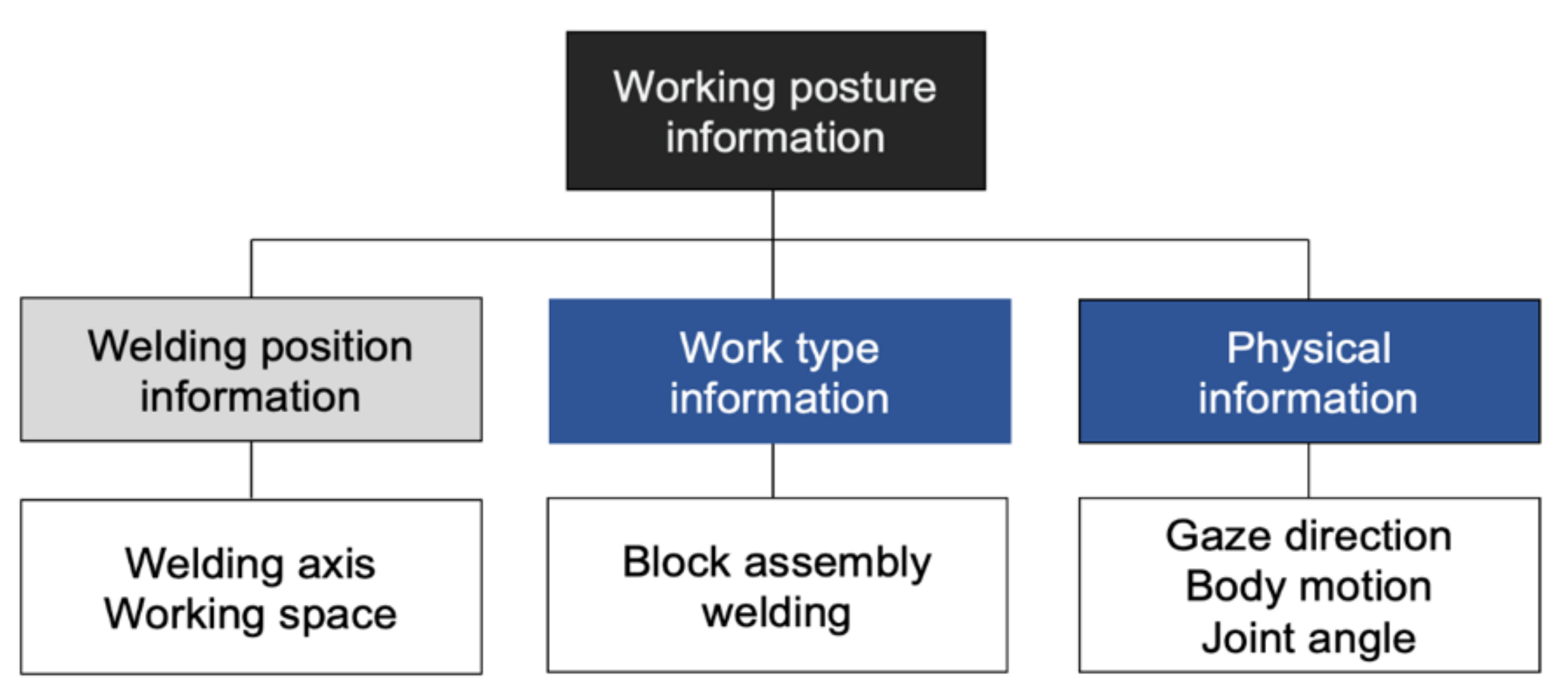
Based on the information of the basic welding axis and working space, new working-posture information, as shown in
Figure 3, was constructed by adding information such as the features of block assembly, gaze direction, and related human factors. It is important to understand the impact of workload by specifically defining the working-posture information generated by manual welding.
Table 2 compares the differences between the proposed and existing welding positions.
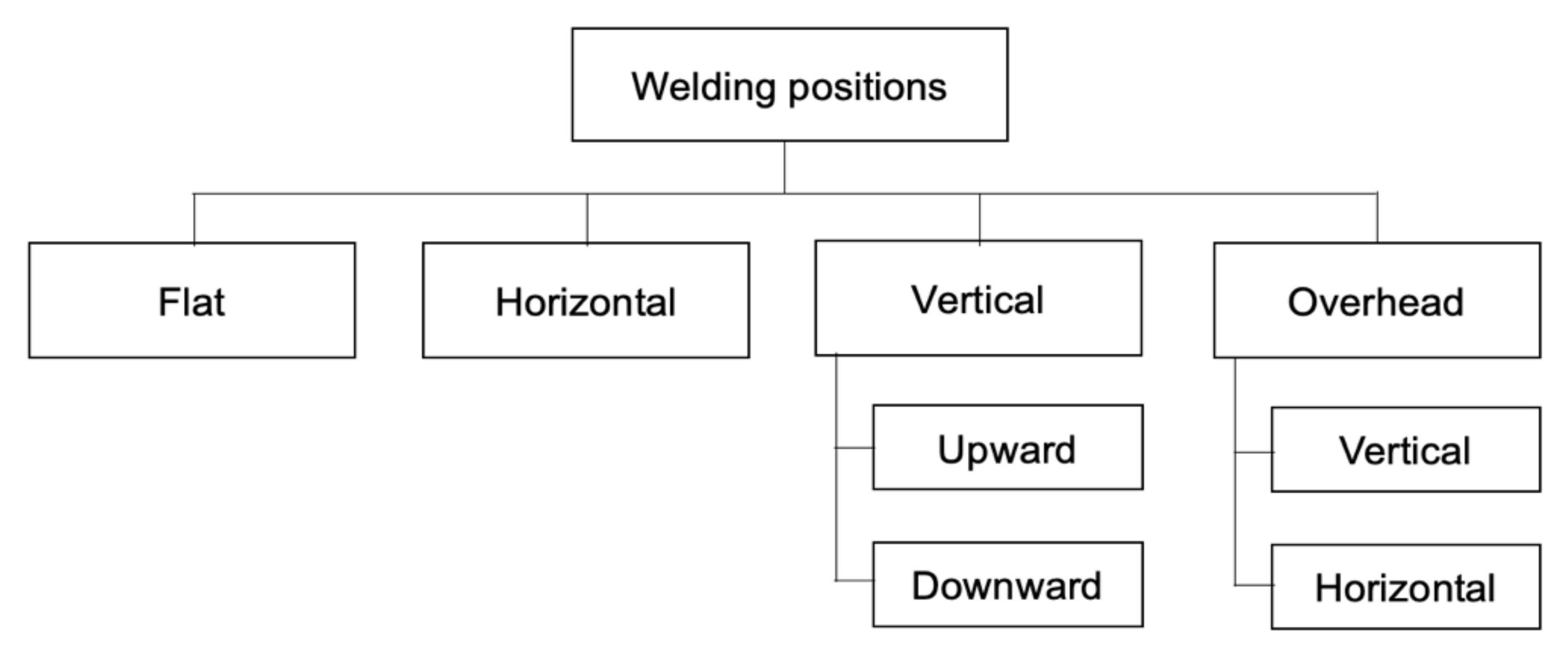
Based on the working-posture information, this study reclassified the welding positions occurring in the shipbuilding production process, as shown in
Figure 4. In the newly proposed classification, to reflect the environmental constraints in the assembly process and the difference in working postures, the vertical and overhead welding positions were added. The subdivision of the overhead welding position reflects the difference in the working posture that occurs depending on the movement of the welding rod either horizontally or vertically. The vertical welding operation was divided into upward and downward positions, where the upward position advances by maintaining the welding rod and the bead perpendicularly, whereas the welding rod faces downward.
2.3. Determination of Physical Information Required for Welding Positions
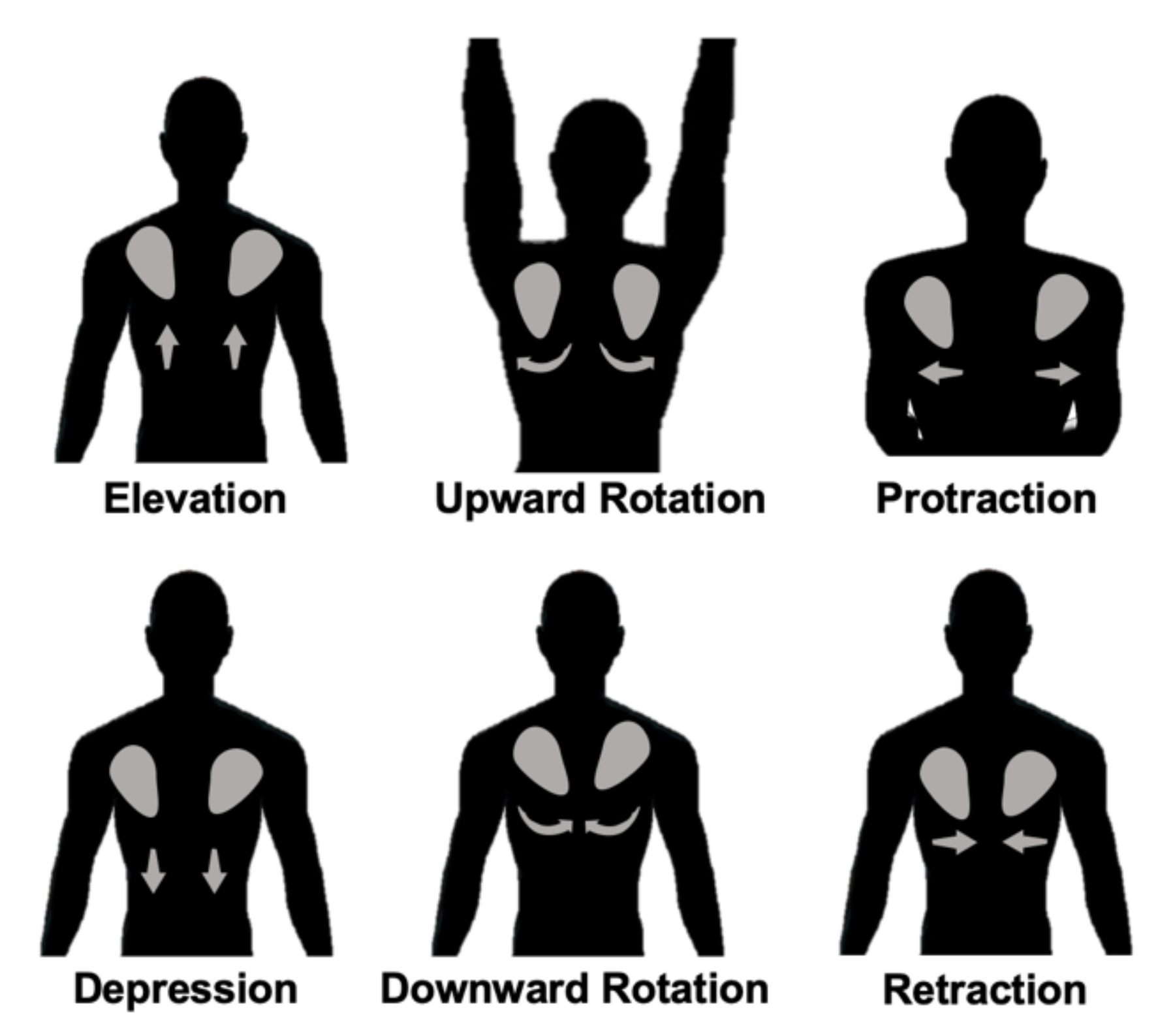
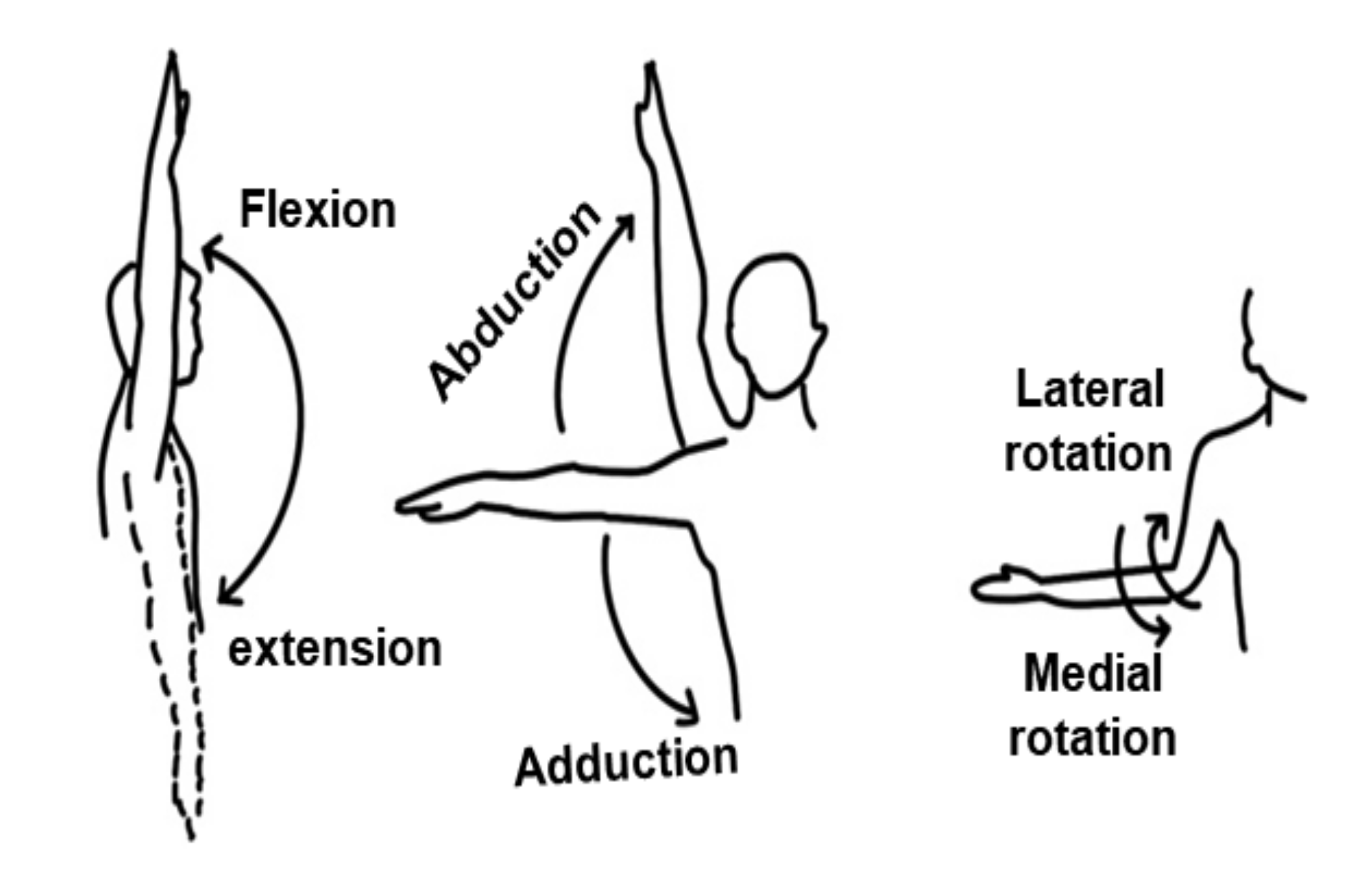
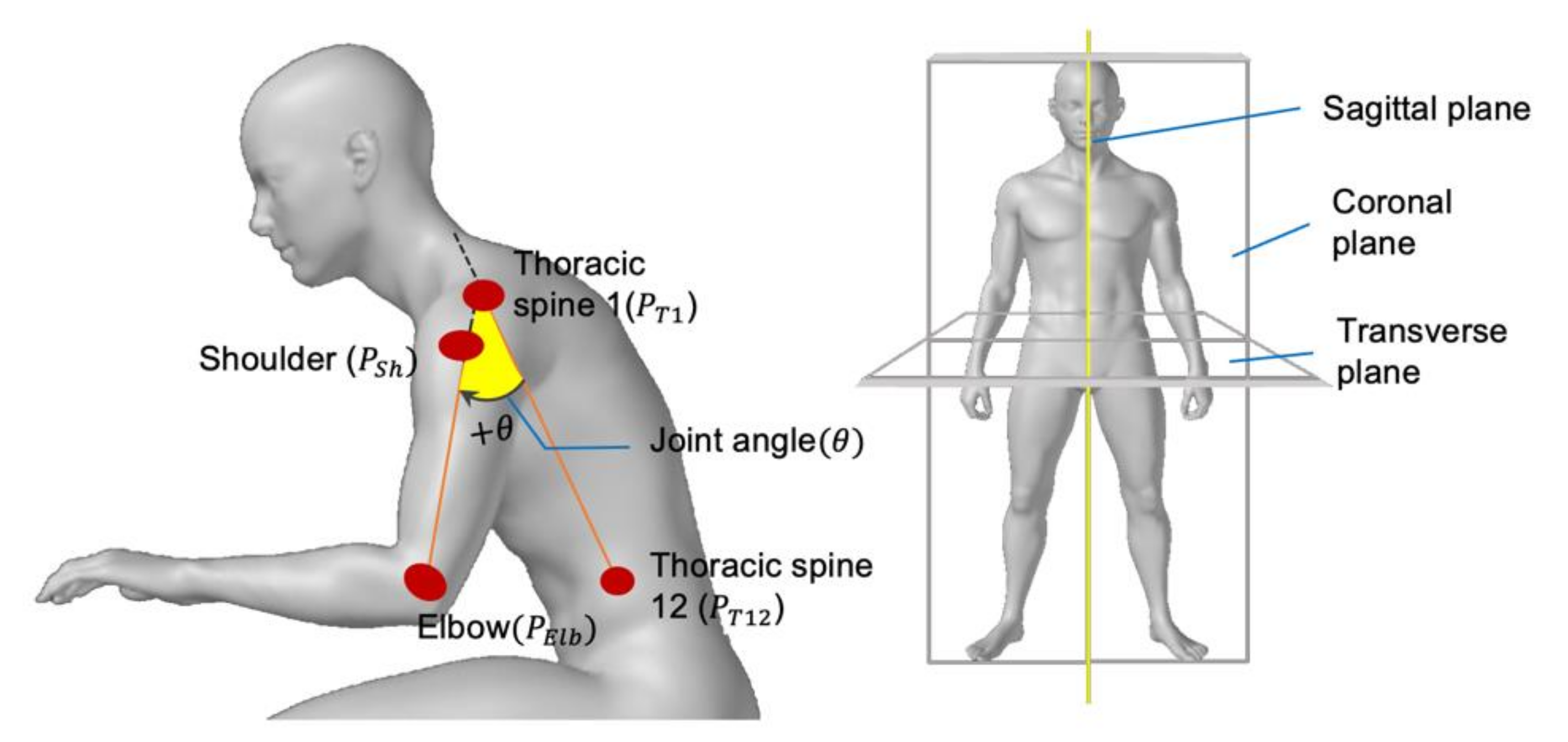
To analyze the newly classified welding positions as per the workload, physical information that determines each position can be exploited. Consequently, it is necessary to investigate the state of the muscles involved in a specific welding position. By reflecting the fact that the body moves around the body joint and the movement of the body joint consequently affects the muscles, the body joints involved in the welding work were selected and the movements of the body joints were examined. The movement of each body joint is expressed by the gaze direction and the body-joint angle.
First, through an interview with welders working at the assembly shop of a shipyard, the body segments, and joints where physical workloads mainly appear were investigated. Interviews were conducted with 12 workers using the survey form shown in
Table A1.
We derived the
p-values using the chi-square test and Fisher’s exact test to identify the relationship between muscles and workloads. Most of the workers responded that the workload on the neck (
), shoulder
), upper arm
), upper back
, and lower back
) was prominent. The summarized
p-value heat map for ten body parts is shown in
Figure 5. The statistical analysis process for the interview results is fully described in
Appendix A.
From the interview results, it can be deduced that the welding work mainly transfers the physical workload to the upper limb joint. The workload on the lower limb varies greatly based on the individual’s disposition, habits, experience, and the presence or absence of equipment.
Subsequently, at the laboratory level, candidate body joints were pre-selected by investigating the workload on the body of the participating men and women. To objectively measure the workload applied to the selected muscles and the connected joints, the motion and its range to be taken by the participants should be provided as a guideline in advance. By following the guidelines, it is possible to prevent ambiguous interpretation of an individual’s posture and thus to reduce the deviation of the participants’ movements. The detailed procedure for the guideline is explained in
Appendix B. As a result, we classified the motions or movement and the joint angles involved in the proposed welding positions considering the gaze direction and associated muscles such as neck, shoulder, and upper arm. The categorized association listed in
Table 3 was used to measure the workload in the following section.
3. Physiological Measurement of Muscles by Surface Electromyography
This section aims to assess the workload exerted on the welder’s body, with a focus on the working posture used in manual welding. To obtain an objective indicator for the workload evaluation, a surface EMG test belonging to the physiological evaluation method was adopted, considering its usability in repeated measurements. The data measured using the test were analyzed and used to calculate the difficulty of the work.
3.1. Surface Electromyography and Muscle Activity
The human body generates various bio-signals through physical and mental activities. These bio-signals include electrocardiography, which measures electrical signals generated from the heart, electroencephalography, which measures electrical signals generated from the brain, and electromyography (EMG), which measures electrical signals generated from muscle activity. Among these, EMG is widely used as an effective tool for muscle-activity research.
EMG is a technique for measuring electrical signals that contain useful information on muscle contraction [
26]. In addition to medical research, it is used as an effective evaluation tool for human motion in various fields such as rehabilitation, ergonomics, and sports. EMG data can be collected using both invasive and non-invasive methods. An invasive method that inserts a needle-shaped electrode into a muscle can provide high-resolution data; however, it is not suitable for repeated use because it causes discomfort to the subject to collect a sufficient amount of data. Moreover, the invasive method cannot measure excessive dynamic motion. By contrast, the non-invasive method reduces discomfort and facilitates repeated measurements because the measurement is performed by attaching a surface electrode to a specific muscle. Consequently, this measurement is called surface electromyography. In this study, non-invasive measurements were performed to facilitate repeated measurements.
3.2. Subjects and Apparatus
For our EMG test, ten healthy participants aged 23–25 years were recruited, as summarized in
Table 4. All participants had prior knowledge of welding in the shipbuilding assembly process through college curriculum and had experience in manual welding through a training course. Prior written consent was obtained from all participants before participating in the experiment, based on the research ethics procedure.
We used commercial surface EMG equipment, manufactured by Lextha Korea, to measure the amount of muscle activity in the required body parts. This device can simultaneously measure up to eight channels with a bipolar surface-type electrode, allowing wireless measurement. If used in an indoor environment with many obstacles, there is a limitation that the measurement must be performed within a radius of 20 m.
3.3. Target Muscle and Electrode Placement
The EMG measurement method depends on the type of electrode. A suitable measurement for dynamic motion in sports or biomechanics is the use of surface electrodes. The disadvantage of this method is that it is difficult to measure the deep muscle, compared to the needle electrode because the electrode can only detect the activation signal of the superficial muscle close to the skin. Nonetheless, this method has been widely used to measure dynamic motion.
As the EMG detects very minute electrical signals generated by muscles, the size of the target muscle and the electrode attachment position are important for stable and accurate signal measurement. The size of the muscle to be measured must be sufficiently large to accommodate the lowest signal strength detected by the electrode. In addition, it is important to select a major muscle and accurately attach electrodes to the muscle.
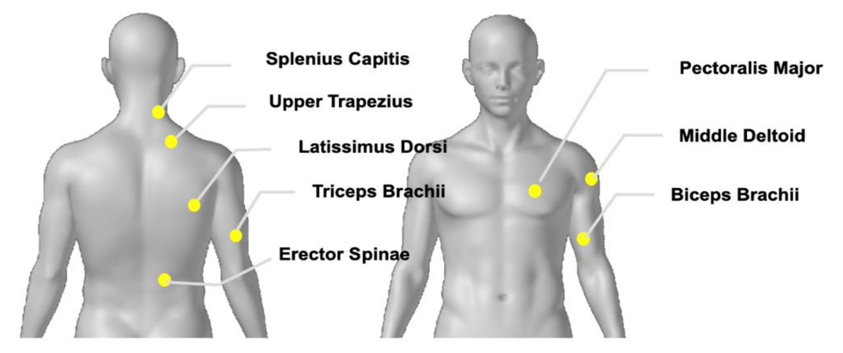
In this study, major joints and body parts were selected based on the results of interviews conducted at the shipyard site. The muscles that govern the movements of the selected major joints and body parts are listed in
Table 5. Here, because the measuring device could measure up to eight channels simultaneously, eight muscles that control the motion were selected.
Figure 6 shows the positions of the target muscles.
The position of an electrode attachment for each muscle was determined by referring to the guidelines of the surface electromyography for the non-invasive assessment of muscle project [
27], known as the international standard.
Table 6 presents a detailed description of the selected muscle, the joints controlled by each muscle, and the position of the electrode attachment.
3.4. Experimental Design
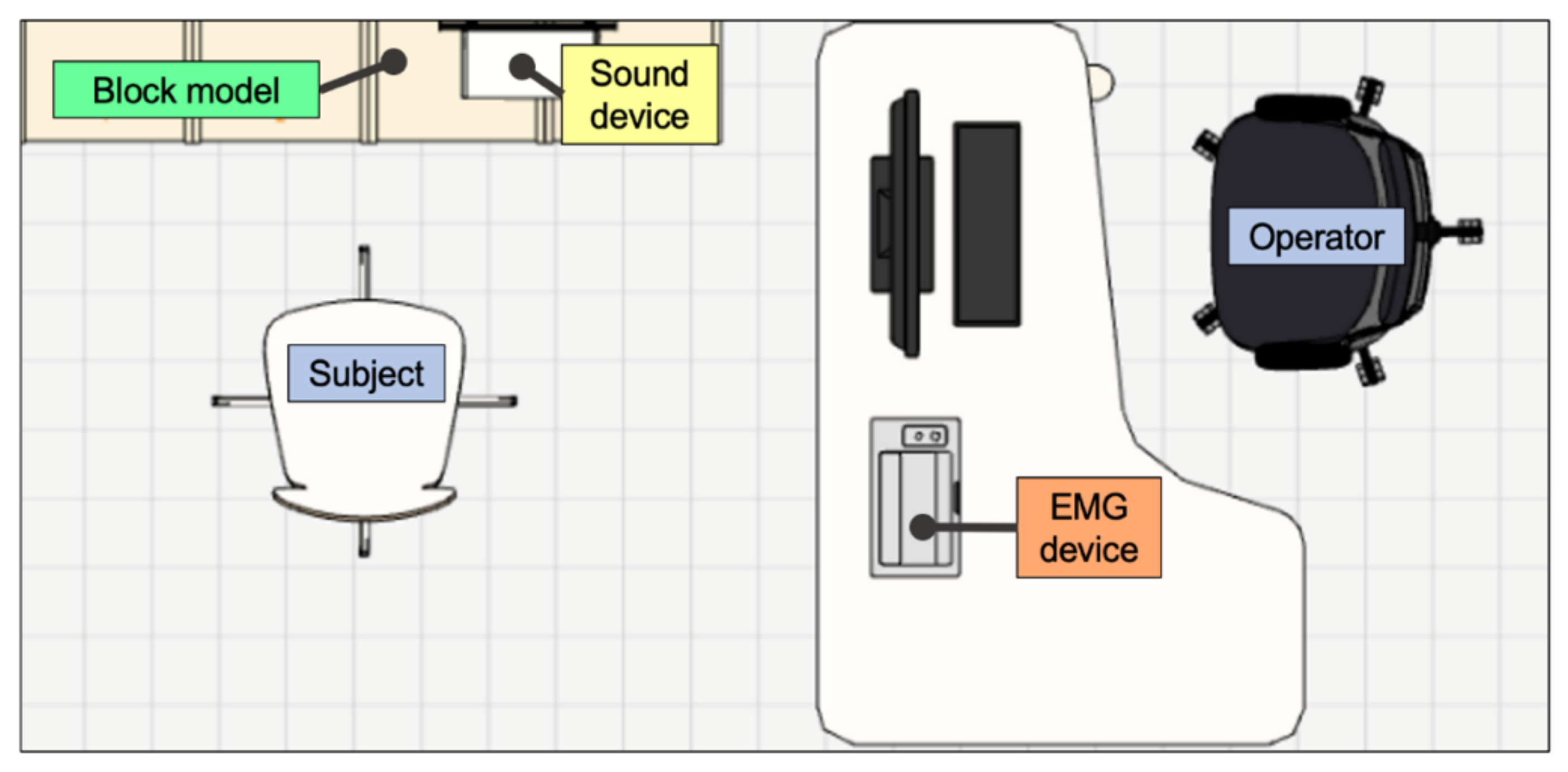
To reproduce the working posture to be similar to that in the field, a welding work environment was prepared as shown in
Figure 7. Even though the experimental block was made of wood, it was intended to reflect the size and shape of real blocks. The work chair was fixed at the same height regardless of the participant’s physical condition. Participants performed welding while holding a dumbbell equivalent to the weight of a welding rod. Measurements were always performed in the morning to minimize the effects of fatigue that may occur after daily activities.
The experimental sequence was as follows: (1) explaining the six welding positions and the experimental procedure to the participant, (2) performing skin preparation to attach the electrodes to the eight selected muscles, (3) measuring stationary EMG signals when the participant was sitting in the work chair, (4) performing welding for 95 s in the order of the randomly selected welding positions, and (5) measuring and collecting EMG data.
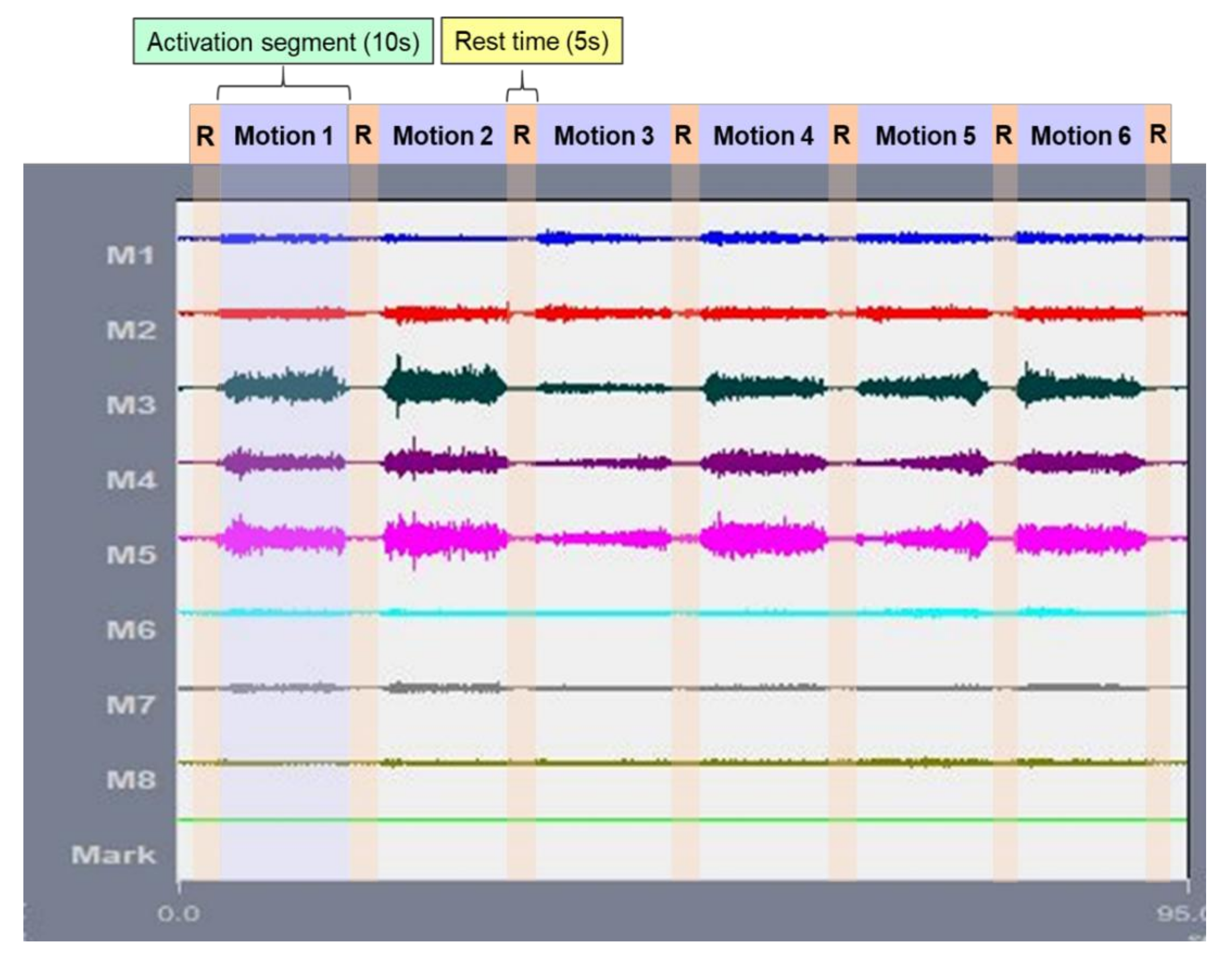
The measurement proceeded with the work–rest iteration shown in
Figure 8. One set was defined as performing all six welding positions, with the participant performing a set for 95 s. The movement of the arm holding the dumbbell was directed to maintain a normal welding speed of 10 cm/s. For this purpose, an auditory cue was given to the participant. There was a 15 min rest period between each set, and up to three sets per day were measured to minimize the effect on fatigue that may result from successive measurements.
3.5. Processing of Measured sEMG Signals
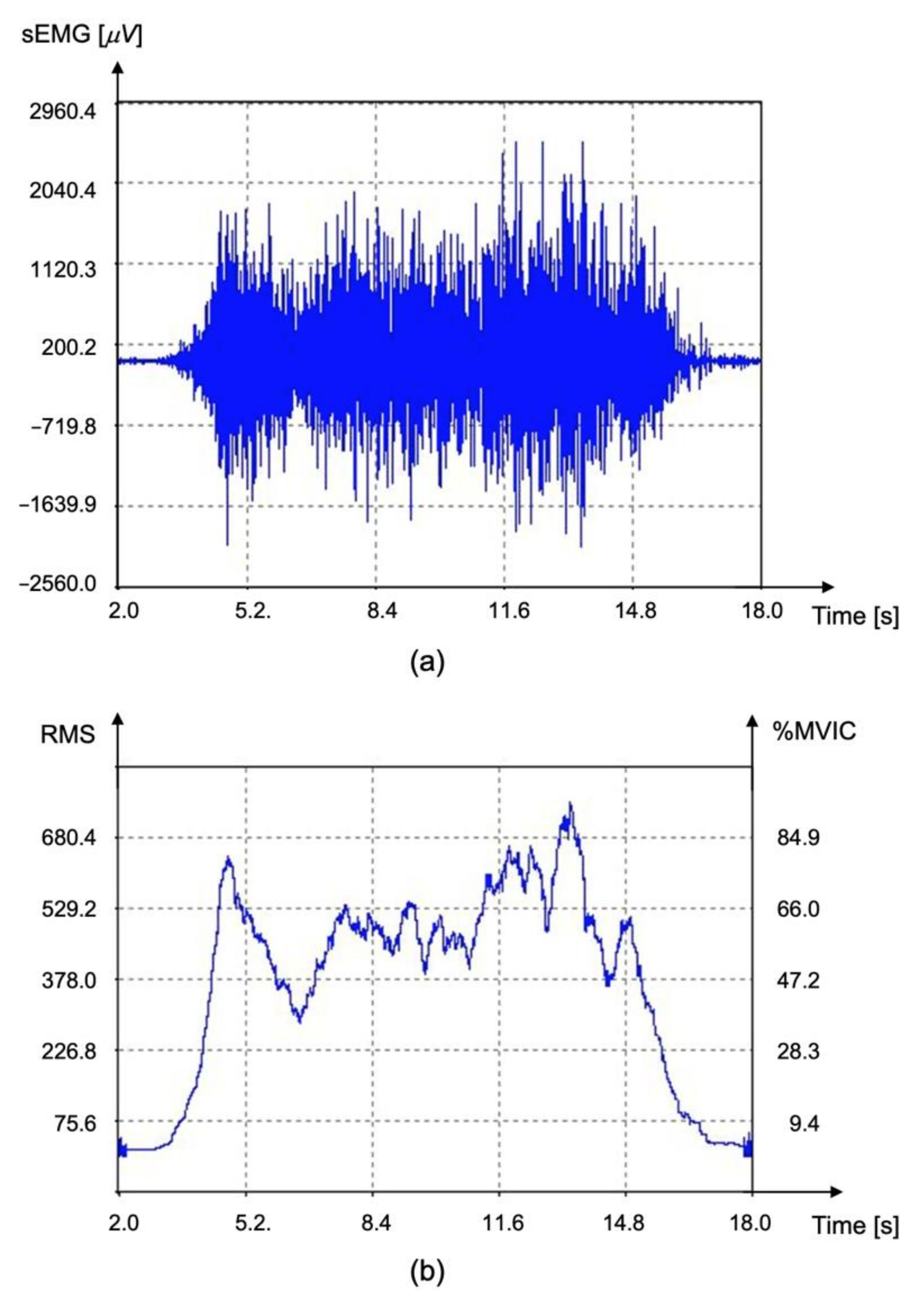
The sEMG measured in the time domain can be quantified as the amount of energy expressed by the muscle through signal analysis. The EMG equipment uses a notch filter to remove the noise generated from the power supply. All stored raw data are rectified after denoising through a high pass filter of 10 Hz and a low pass filter of 300 Hz. In this study, we used a method to quantify the measurement signal using root mean square (RMS) and maximum voluntary isometric contraction (MVIC).
First, the noise included in the signal was eliminated using RMS conversion. RMS conversion is a method of calculating an average value using a low-pass filter or an appropriate window after undergoing a rectification process. Consequently, it is possible to obtain a linear envelope shape in which the noise is mostly removed [
28,
29,
30].
The RMS value is affected by individuality such as the subject’s age, sex, muscle size, skin thickness, and muscle fatigue state. To avoid errors in analysis owing to the differences in individual characteristics, the MVIC that normalizes the amplitude with a reference value was used. MVIC refers to the maximum amount of contraction that a specific muscle can voluntarily produce. A value normalized between 0 and 100 by dividing the muscle signal value appearing in an arbitrary motion by the MVIC was defined as %MVIC.
Figure 9 shows the process of deriving the %MVIC of the sEMG signal obtained from the middle deltoid muscle.
The measured muscle activity
for welding position p and muscle m was recorded at the corresponding cell, as presented in
Table 7.
4. Assessment of Welding Factor in the Physical Domain
A work-difficulty function was proposed to quantify the collected EMG data as an influencing factor on the welding workload in shipbuilding. The proposed function assumes that there is a proportional relationship between EMG data and physical workload. The main elements necessary for calculating the work difficulty were first identified, and a method to measure the work difficulty is suggested.
4.1. Definition of Physical Welding Factor
Based on ergonomic studies, the higher the difficulty or complexity of the work, the higher the likelihood that the worker will have trouble performing the work and will thereby cause errors. Additional actions to correct the errors may result in increased work hours or delays.
Work difficulty or complexity can be divided into two types: physical and mental. As this study emphasized working postures, work difficulty could be explained in terms of the degree of muscle consumption. Therefore, we proposed a difficulty factor explaining the amount of physical effort consumed when performing a specific work, focusing on welding positions.
When performing manual welding in the shipbuilding process, the workload is concentrated on a specific body part of the worker. As the shape of the assembly delivered to the worker in a particular shop is similar, the worker will perform the welding with repeated postures, which can cause strain to certain muscles and body parts. Therefore, it is necessary to establish a basis for calculating the level of work difficulty in the physical domain. The work difficulty caused by the workload of manual welding is formulated as a physical welding factor hereinafter.
4.2. Physical Welding Factor by Muscle Activity
The biometric dynamics analysis of human or animal movements can be revealed using an EMG test. As the relationship between the amplitude caused by the EMG test and the force generated by the muscle contraction is linear [
31,
32], we could utilize this linearity to estimate the workload exerted on the muscle. The amplitude of EMG, which can be a numerical representation of muscle response to nerve stimulation, was defined as muscle activity. This value was represented by the physical effort consumed during a specific working posture.
Work difficulty should be expressed as a representative value for each working posture, based on all the muscles involved. In the case of using an electromyography device, the measured muscle activity in each muscle can be compared relative to the body consumption among muscles using a normalized process. However, because the muscle activity for a specific posture is expressed as a set of all the muscle expenditures involved, it is not reasonable to quantify the muscle activity for each posture by simply adding each normalized muscle activity.
In this study, to recognize the difference in muscle activity among muscles for one working stage, a method of expressing the muscle activity of all selected muscles in a linear combination was proposed. First, the measured muscle activities were added based on two consecutive factors: posture contribution ratio and muscle-activity weight. The posture contribution ratio represents the individual muscle strength occurring in each muscle in a working posture, whereas the muscle-activity weight accounts for the intermuscular influence. Subsequently, the two factors were linearly combined to derive the final muscle activity for a specific posture.
4.2.1. Posture Contribution Ratio
The work-characteristic factor (
) is the average of the muscle activities consumed when performing any work and is not limited to a particular posture. That is, irrespective of the welding position,
is the average muscle activity expressed in individual muscles during manual welding. The work-characteristic factor is defined by Equation (1):
where the subscripts
and
refer to the p-th welding position and m-th muscle, and
and
are the numbers of welding positions and muscles, respectively. N is the number of samples, and
is the average value of the %MVIC value in groups
and
participating in the measurement. The measured muscle activity,
tabulated in
Table 7, is the %MVIC value at
and
. When performing manual welding, the selected muscle physically consumes the average muscle strength as much as the work-characteristic factor.
The posture contribution ratio (
), defined in Equation (2), is the ratio of a particular posture
to the average of the muscle activities accumulated by all the working postures of a particular muscle
. If the ratio exceeds 1, posture
consumes more energy than the average for a muscle
.
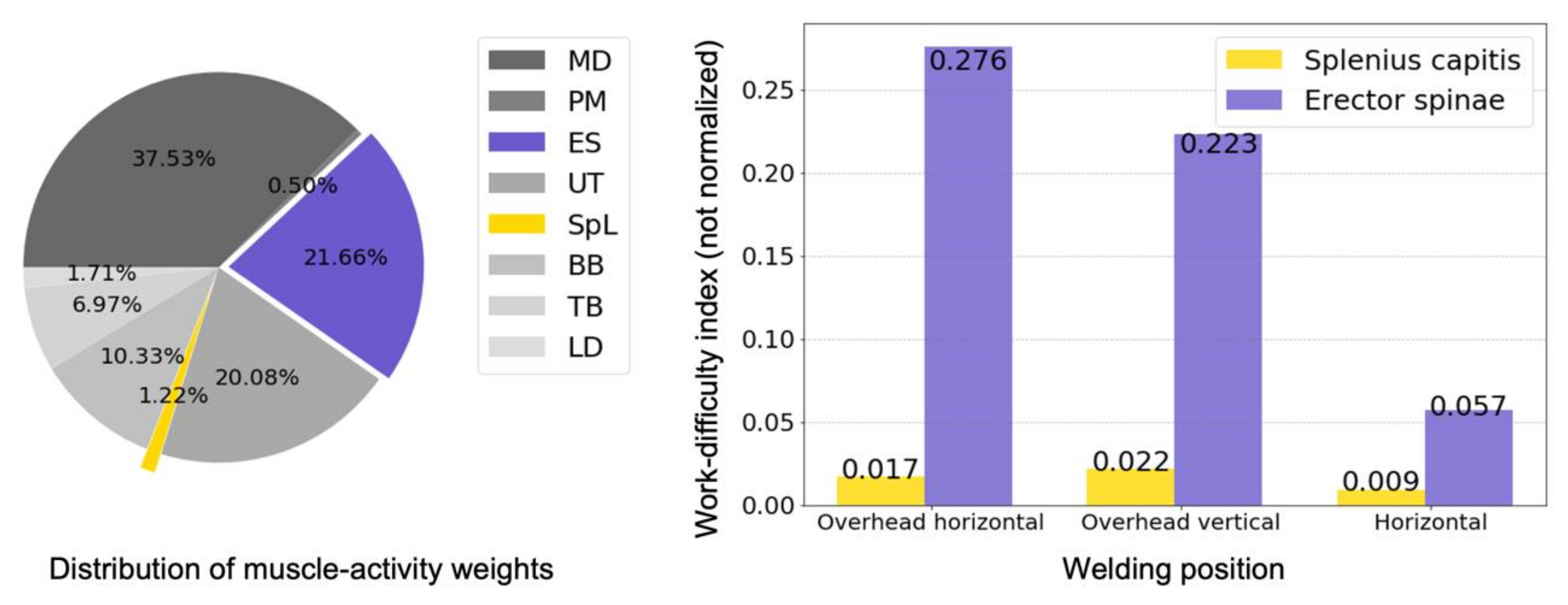
Figure 10 shows the effect of the posture contribution ratio on manual welding. The left figure represents the amount of muscle activity of the erector spinae (ES) and splenius capitis (SpL) for each welding position, and the right figure compares the degree of contribution to the three working positions, considering
.
Comparing the muscle activity of the two muscles, in all welding positions, the muscle activity of the ES was overwhelming compared to the SpL. However, in terms of contribution, the SpL was larger than the ES in overhead and horizontal welding positions. In the case of the posture contribution ratio only, this means in the above three positions, the ES, exhibiting approximately 30 times more muscle activity than the SpL, consumed physical effort at a relatively smaller rate than the SpL. As
is calculated based on the work-characteristic factor (
), each muscle is more affected by the average muscle activity. When only the contribution ratio is applied, as shown in
Figure 10, the muscle characteristics shown in the muscle-activity value (or row data) may not be sufficiently reflected. Consequently, the relative difference among muscles was not considered, which raised the need for another factor to consider the relative differences.
4.2.2. Muscle-Activity Weight
The human body is composed of an aggregate of many muscles. Thus, the contraction and relaxation of various muscles occur simultaneously when performing dynamic movements. As body movement is performed due to the collaboration of the associated muscles, the individual muscle activity and the relative involvement of related muscles should be considered. In this study, we introduced the concept of weights to impart relative priority among the muscles used in the measurement.
The muscle-activity weight (
), Equation (3), is defined as the ratio of the muscle activity of a particular muscle m to all muscle activities in all postures:
Figure 11 shows the distribution of muscle-activity weights and the results of muscle activity applied to the three welding positions. As muscle-activity weight is the activity of an individual muscle compared to the sum of muscle activities in all positions,
of each muscle considers the relative influence of the muscles involved. When
was considered, as shown on the right side of
Figure 11, the ES yielded a larger value compared to the SpL. It is further inferred that these results are based on the characteristics of each muscle. The SpL, a single muscle that extends from the lower cervical spine to the head, serves to lift the neck and head and performs an extension exercise. By contrast, the erect muscle, ES, plays a major role in fixing other parts of the body during movement. To withstand the load that appears in a movement, the ES is composed of many muscles, such as spinalis, longissimus, and iliocostalis. The ES mobilizes a greater number of muscle fibers for movement, which may explain the high contribution of the ES.
4.2.3. Derivation of Physical Welding Factor
The physical welding factor, a function that represents physical work difficulty in welding, is formulated in Equation (4) as the linear combination of the contribution of each muscle’s workload multiplied by its weight:
If the weight in Equation (4) is divided by the total muscle activity, as shown in Equation (5), the factor can be expressed as a matrix product in Equation (6).
4.3. Application of Physical Welding Factors and Discussions
Manual welding is a representative example of a process in which the working posture is an important variable. Recognizing that different assembly man-hours are calculated depending on the welding positions, most shipyards have been developing and utilizing the welding factor for each welding position. The work difficulty of the welding position that is known to be difficult in the field, increases as expected. The physical welding factor proposed in this study also shows the work difficulty in proportion to the working posture.
Unlike the concept of welding factors developed by shipyards, this study focused on the difficulty of welding based on the workload on the body. To interpret the motion of the human body in terms of power consumption, the main purpose of our study was to express the degree of work difficulty, and not just the man-hours required for the work.
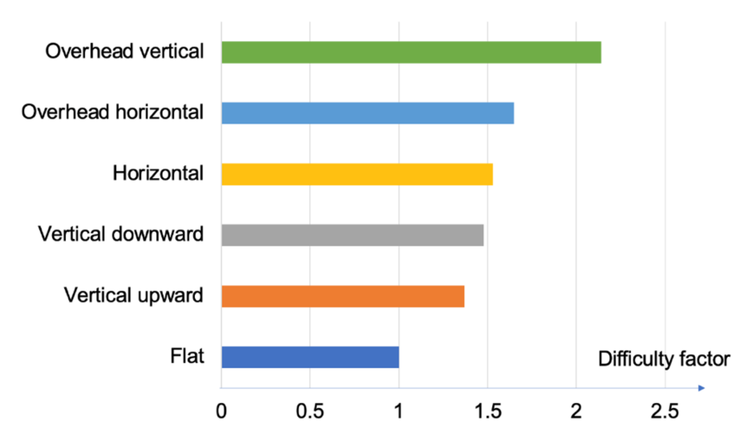
The resulting values of the proposed physical welding factor are depicted in
Figure 12. All values were adjusted based on the value of the flat position for each method. The result shows a larger value in the overhead welding position than in the horizontal or vertical positions. In the overhead welding position, the value along the vertical direction was larger than that in the horizontal direction. These results were expected from interviews. The result also shows that the horizontal welding position had a larger value than the vertical position. This was presumably due to the greater arm movement in the horizontal position. Since vertical welding is generally performed in a narrower space than horizontal welding, the arm and body of the welder are more closely attached to maintain a stable posture, which results in the lower difficulty factor.
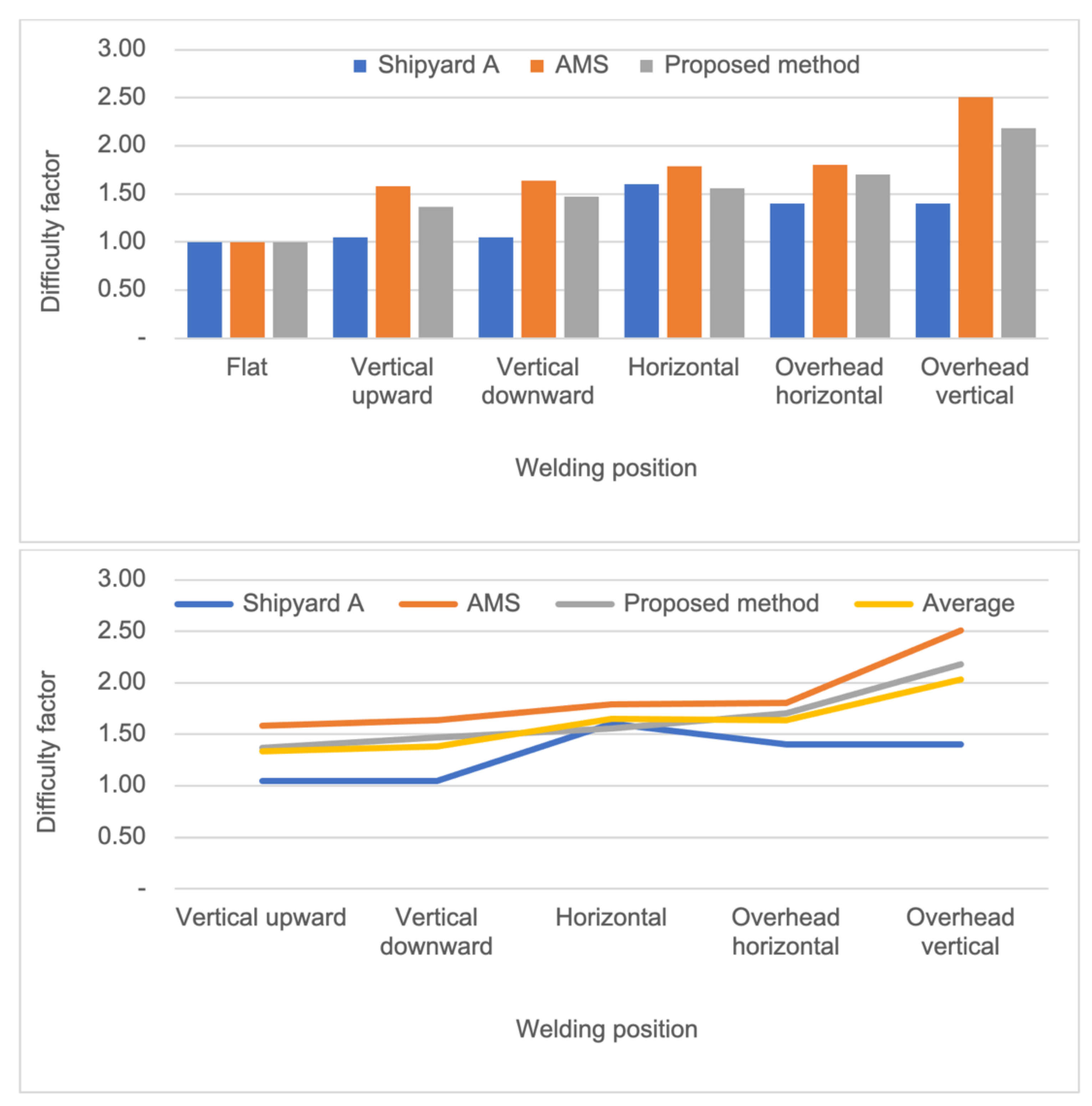
Three different factors were used to compare the degree of influence of the welding task: the welding factor used in Shipyard A, the result of the work attitude analysis by the musculoskeletal simulation package Anybody Modeling System
® (AMS), and the physical welding factor proposed in this study. As these test indexes are dimensionless, we can compare their quantitative results to determine the differences or tendencies of the work-difficulty factors with the welding positions involved. The comparative results are presented in
Figure 13. All results were adjusted based on the value of the flat position for each method.
The musculoskeletal simulation data were produced by entering the welding positions into the widely used commercial software AMS [
33]. The results obtained by the musculoskeletal simulation showed a trend similar to that of the proposed result. The reason is presumed to be that both results were based on body movement and muscle activity. From this result, it can be confirmed that the physical welding factor developed in this study reflects the effect of muscle consumption.
The high value of the horizontal position in Shipyard A (Note that Shipyard A does not distinguish the horizontal/vertical postures in the overhead welding position and the upward/downward directions in the vertical position. The reason for this might be the limited data availability.) was analyzed as the difference in the weaving action performed to prevent defects in the welded part. For example, in the case of horizontal welding, welders make efforts to reduce welding defects by adjusting the welding speed, which soon appears as an increase in the welding factor. By contrast, in overhead welding, because there is a high possibility that the bead flows down to the welder’s face or body, a method of reducing the arc and increasing the welding speed is adopted to reduce the amount of flowing bead to a possible minimum. Therefore, the overhead welding position resulted in a smaller welding factor compared to the horizontal position. This result can be interpreted as a combination of the worker’s safety guarantee and the shipyard’s quality control requirements, meaning, the influence of the working posture diminishes irrespective of the actual workload. It should be noted that when the external factor is relatively higher than the working position itself, a comparison with other indicators should be performed carefully.
In summary, the results of welding influencing factors are inevitably different because each organization has a different approach or concept in calculating work difficulty. Further, the welding factors used in shipyards include their know-how and confidential information, and thus it is almost impossible to estimate the process of deriving the factors. Here, we can only confirm our results with publicly available data or numbers revealed through consultation with those working at a shipyard. Therefore, it is more reasonable to identify the overall trend and suggest a range of work difficulties, rather than focusing on the individual values for each position. The proposed method can be extended to shipyards by further studying and including the practical factors used in shipyards through mutual cooperation.
5. Conclusions
A quantitative work-difficulty calculation to derive the physical welding factor was proposed for manual welding, where the working posture is an important variable. First, new standardized welding positions were established by analyzing all the welding positions appearing in the assembly process of shipyards. New working-posture information was constructed by including detailed factors such as the features of block assembly, gaze direction, and related human factors.
To understand the work difficulty in terms of the amount of physical effort consumed when performing welding, a physical workload evaluation was performed. For a more accurate and objective evaluation of the workload on the body, the surface electromyography method was adopted, and a muscle-activity test was performed on the recruited test subjects. The distribution of muscle activity collected through electromyography was analyzed, and a work-difficulty function was presented to quantify the difficulty of the welding work.
The validity of the proposed method was verified by comparing its results with a set of actual shipyard data and musculoskeletal simulation results. As the welding factors obtained from the different methods included in the comparison were calculated differently from each other, the absolute comparison was meaningless. Nonetheless, similar trends were observed for the main indicators. In particular, the musculoskeletal simulation data showed a similar trend as our method by yielding very small numerical errors with a standard deviation of 0.12.
It was found that external factors such as work preparation or quality-control issues other than the working posture were included in the results of the shipyard, which resulted in a considerable difference between the shipyard’s welding factors and the proposed physical welding factors, particularly in the horizontal welding position. The work practice of a shipyard should be added to the derivation of the physical welding factor proposed in this study to closely simulate the welding factor used in actual shipyards. In the case of welding, which differs based on the equipment, construction method, and skill level of the welder for each shipyard, it is suggested that both the environmental factors and the physical workload should be interrelated in future research.
Unlike the welding factor of shipyards based on experience, the physical welding factor can be systematically derived in a laboratory environment. The proposed method provides the advantage of fundamentally improving the current database-construction method which has been a stumbling block in the development of existing welding influencing factors. Although this study focused on the process of manual welding, it is fundamentally based on general working postures. If expanded, it is possible to not only update the welding factor of shipyards but also provide the basis for the relevant man-hour estimation. Large shipyards can review and analyze the method of welding factor derivation that has been difficult to analytically formulate. In particular, the proposed method can be easily applied to small and medium-sized shipyards and subcontractors, where it was impossible to consider the effect of welding work and thus to predict the workload.


