
The Simulation of Sloped Bank Effect Influence on Container Ship Trajectory


Abstract
1. Introduction
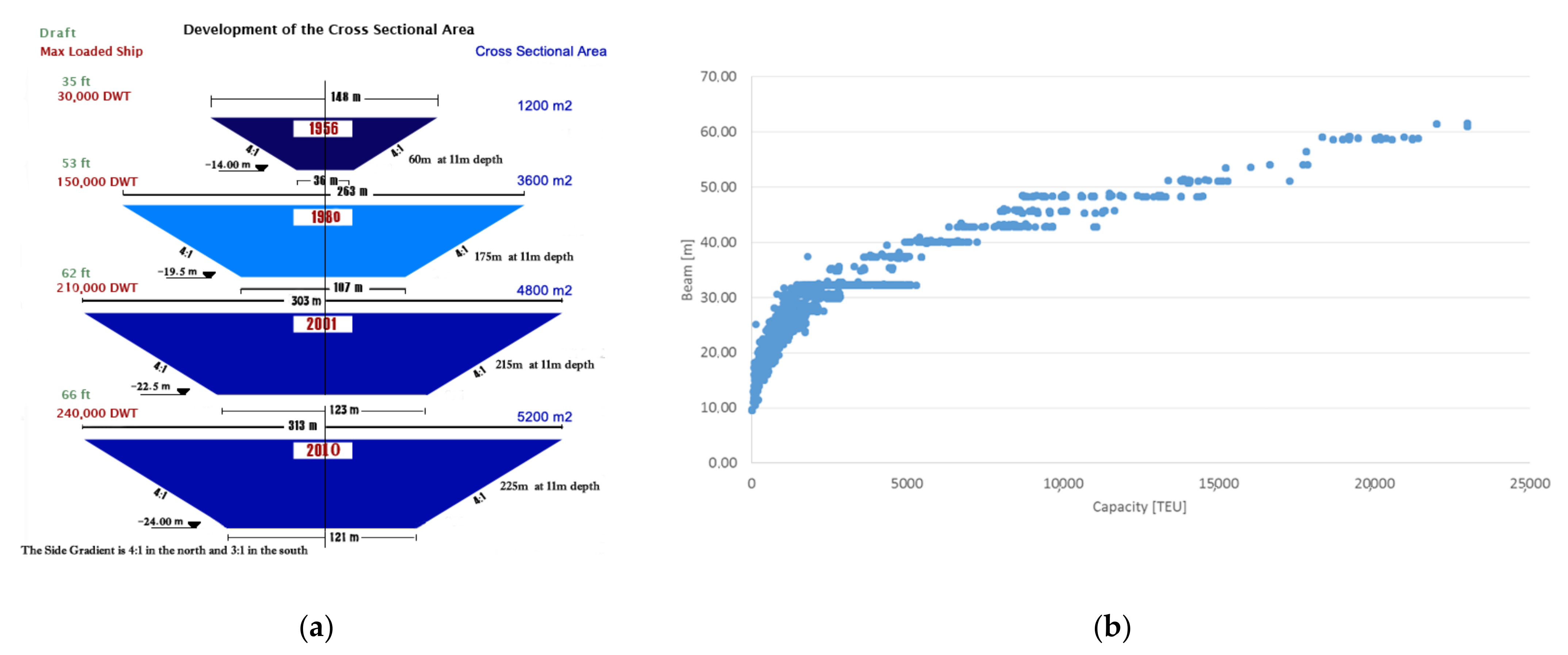
2. Bank Effect and Channel Design Standards
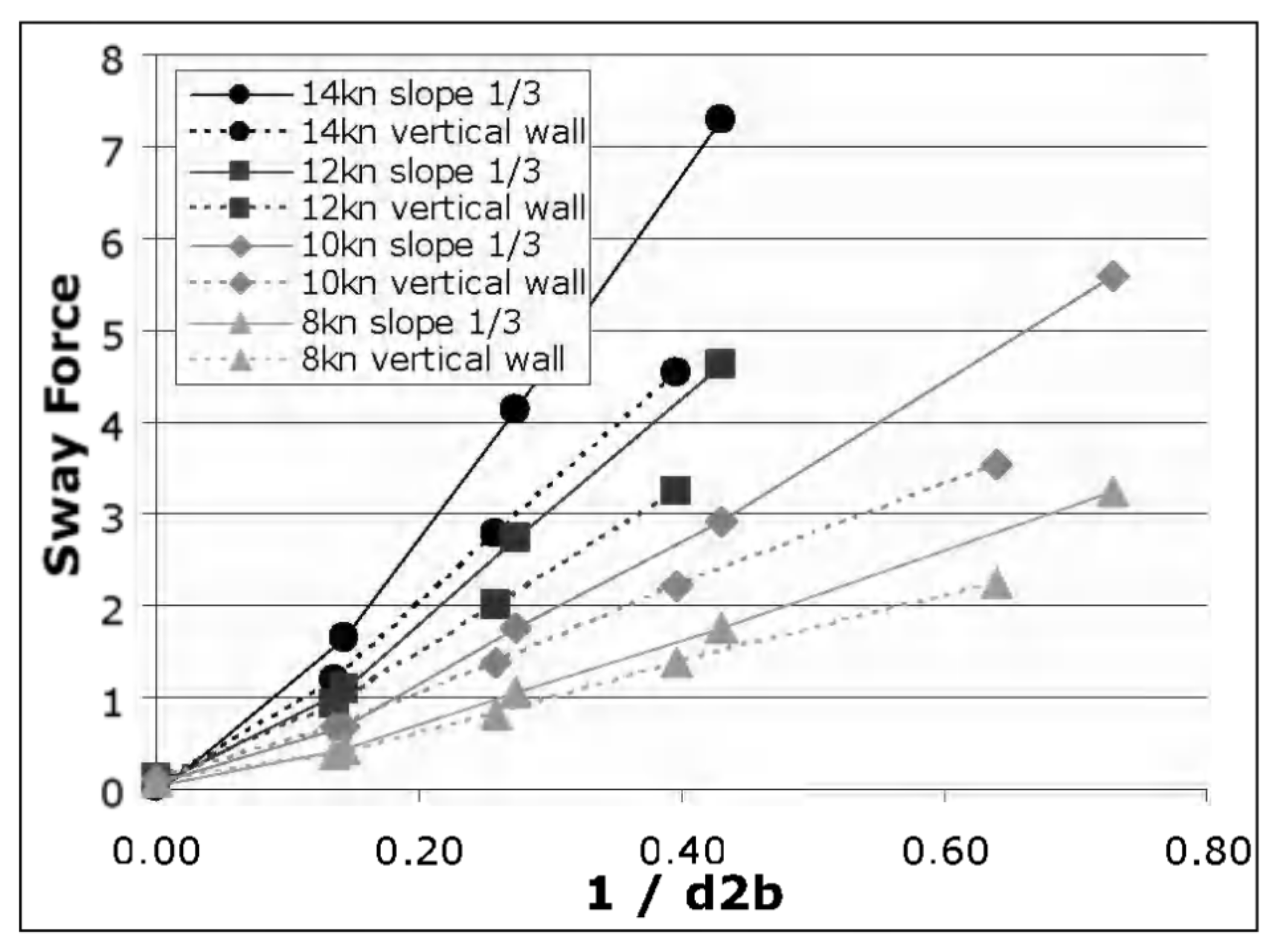
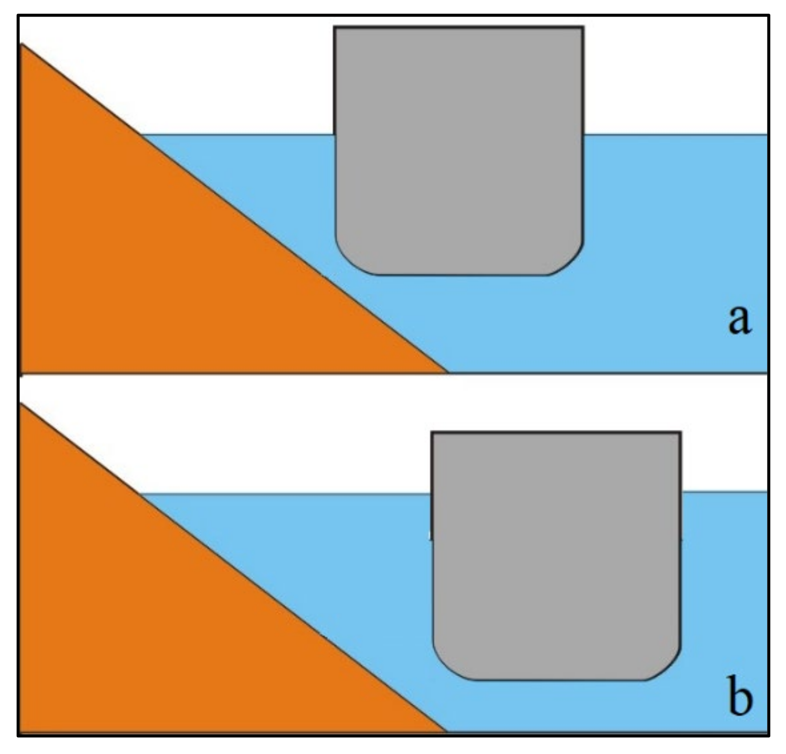
3. The Bank Effect of Sloped Banks
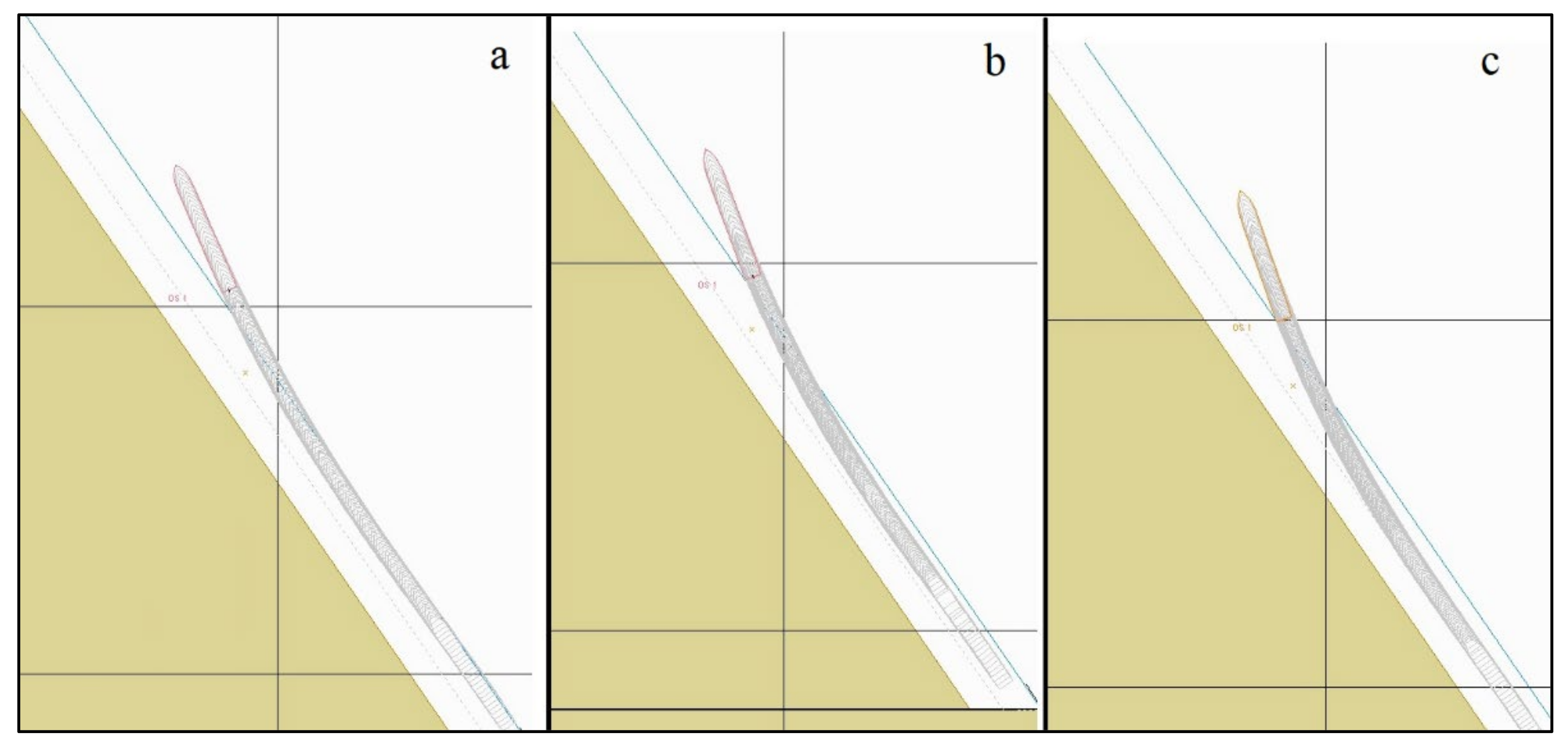
4. Simulation of Sloped Bank Effect on Large Container Vessels
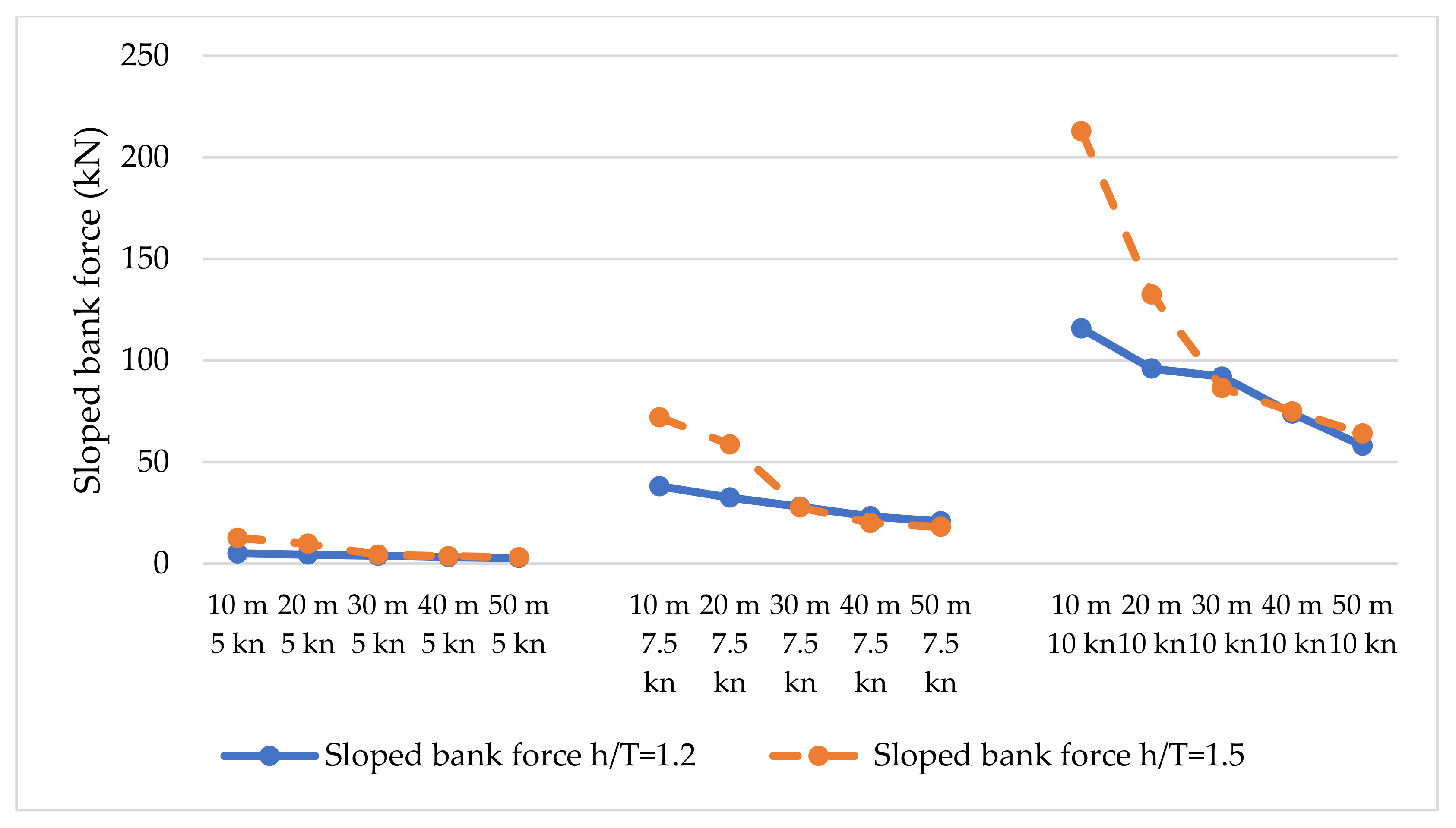
5. Discussion
6. Conclusions
Author Contributions
Funding
Institutional Review Board Statement
Informed Consent Statement
Data Availability Statement
Conflicts of Interest
References
- Suez Canal Authority. Annual Report 2019; Planning & Research Department, Information Center, Suez Canal Traffic Statistics: Ismailia, Egypt, 2019.
- Allianz Global Corporate & Speciality. Safety and Shipping Review 2020; Alliant Global Corporate and Speciality: Berchem, Belgium, 2020. [Google Scholar]
- Transport Malta. Marine Safety Investigation Report, APL Danube, Report No. 08/2020; Marine Safety Investigation Unit: Furjana, Malta, 2020.
- Marine Casualty Specialists. Available online: http://www.maricaspe.com/ (accessed on 10 May 2021).
- Lataire, E.; Vantorre, M.; Laforce, E.; Eloot, K.; Delefortrie, G. Navigation in Confined Waters: Influence of Bank Characteristics on Ship-Bank Interaction. In Proceedings of the International Conference on Marine Research and Transportation, ICMRT, Naples, Italy, 28–30 June 2007. [Google Scholar]
- Serban, P.S.; Panaitescu, V.N. Simulation of ship to shore interaction in shallow and narrow waters. Sci. Bull. Mircea Cel Batran Nav. Acad. 2015, 18, 112. [Google Scholar]
- Sian, A.Y.; Maimun, A.; Priyanto, A.; Ahmed, Y.M. Assessment of Ship-Bank Interactions on LNG Tanker in Shallow Water. J. Technol. 2014, 66, 141–144. [Google Scholar] [CrossRef][Green Version]
- Eloot, K.; Vantorre, M. Ship behaviour in shallow and confined water: An overview of hydrodynamic effects through EFD. In Proceedings of the AVT-Specialists’ Meeting on Assessment of Stability and Control Prediction Methods for Air and Sea Vehicles, Portsdown, UK, 11 October 2011. [Google Scholar]
- Permanent International Association of Navigation Congresses (PIANC). Harbour Approach Channels Design Guidelines; Report No. 121–2014; PIANC MarCom Working Group 30: Brussels, Belgium, 2014. [Google Scholar]
- Del Estado, P. Recommendations for Maritime Works (Spain) ROM 3.1-99: Designing Maritime Configuration of Ports, Approach Channels and Floatation Areas. Spain CEDEX. 1999. Available online: https://www.puertos.es/es-es/BibliotecaV2/ROM%203.1-99%20(EN).pdf (accessed on 14 November 2021).
- Ministry of Land, Infrastructure, Transport and Tourism (MLIT). Technical Standards and Commentaries for Port and Harbour Facilities in Japan; OCDI: Tokyo, Japan, 2009. Available online: https://ocdi.or.jp/tec_st/tec_pdf/tech_00H.pdf (accessed on 14 November 2021).
- Suez Canal Authority. Available online: https://www.suezcanal.gov.eg/English/About/SuezCanal/Pages/CanalCharacteristics.aspx (accessed on 10 May 2021).
- Container-Ship Size: What Dimensions Can We Expect to See? Available online: https://piernext.portdebarcelona.cat/en/mobility/container-ship-size/ (accessed on 10 August 2021).
- Vantorre, M.; Delefortrie, G.; Eloot, K.; Laforce, E. Experimental investigation of ship-bank interaction forces. In Proceedings of the International Conference MARSIM, Kanazawa, Japan, 25–28 August 2003. [Google Scholar]
- Baric, M.; Mohovic, R.; Mohovic, D. Determining Restricted Fairway Additional Width due to Bank Effect for Fine Form Vessels. J. Navig. 2019, 72, 1435–1448. [Google Scholar] [CrossRef]
- Kim, I.; Chae, C.; Lee, S. Simulation Study of the IAMSAR Standard Recovery Maneuvers for the Improvement of Serviceability. J. Mar. Sci. Eng. 2020, 8, 445. [Google Scholar] [CrossRef]
- Hörteborn, A.; Ringsberg, J.W. A method for risk analysis of ship collisions with stationary infrastructure using AIS data and a ship manoeuvring simulator. Ocean Eng. 2021, 235, 109396. [Google Scholar] [CrossRef]
- Szlapczynski, R.; Szlapczynska, J. A ship domain-based model of collision risk for near-miss detection and Collision Alert Systems. Reliab. Eng. Syst. Saf. 2021, 214, 107766. [Google Scholar] [CrossRef]
- Androjna, A.; Perkovič, M.; Pavic, I.; Mišković, J. AIS Data Vulnerability Indicated by a Spoofing Case-Study. Appl. Sci. 2021, 11, 5015. [Google Scholar] [CrossRef]
- Park, D.J.; Yim, J.B.; Yang, H.S.; Lee, C.K. Navigators’ Errors in a Ship Collision via Simulation Experiment in South Korea. Symmetry 2020, 12, 529. [Google Scholar] [CrossRef]
- Yim, J.-B.; Park, D.-J.; Youn, I.-H. Development of navigator behavior models for the evaluation of collision avoidance behavior in the collision-prone navigation environment. Appl. Sci. 2019, 9, 3114. [Google Scholar] [CrossRef]
- Łazuga, K.; Minh, Q.N.; Gucma, L. Cost-Effective Design of Port Approaches Using Simulation Methods Based on the Example of a Modernized Port in the Ustka. J. Mar. Sci. Eng. 2021, 9, 211. [Google Scholar] [CrossRef]
- Žagar, D.; Svetina, M.; Košir, A.; Dimc, F. Human factor in navigation: Overview of cognitive load measurement during simulated navigational tasks. J. Mar. Sci. Eng. 2020, 8, 775. [Google Scholar] [CrossRef]
- DNV Statement of Compliance. Bridge Operation Simulator, Navi-Trainer NTPro 5000, Class A Standard for Certification of Maritime Simulators No. 2. Sandefjord. 2012. Available online: https://www.transas.com.ua/certificates-sim/SIM%20-%20002%20121218%20DNV.pdf (accessed on 14 November 2021).
- Transas MIP Ltd. Description of Transas Ship Motion Mathematical Model; Version 2.11; Transas MIP Ltd.: Cork, Ireland, 2012; pp. 62–63. [Google Scholar]
- Lataire, E. Experiment Based Mathematical Modelling of Ship-Bank Interaction. Ph.D. Thesis, Ghent University, Ghent, Belgium, 2014. [Google Scholar]
- Böttner, C.-U. Ship handling simulation in approach channel and harbour design. In Proceedings of the 34th PIANC World Congress: Connecting Maritime Hubs Globally, Panama City, FL, USA, 7–11 May 2018. [Google Scholar]
- Senčila, V.; Zažeckis, R.; Jankauskas, A.; Eitutis, R. The Use of a full mission bridge simulator ensuring navigational safety during the Klaipeda Seaport development. TransNav Int. J. Mar. Navig. Saf. Sea Transp. 2020, 14, 417–424. [Google Scholar] [CrossRef]
- Czaplewski, K.; Zwolan, P. Using the software of Navi-Trainer PRO 5000 simulator for assessment of the designed navigational infrastructure. Pol. Nav. Acad. Annu. Navig. 2011, 18, 55–68. [Google Scholar]
- Perkovic, M.; Brcko, T.; Luin, B.; Vidmar, P. Ship handling challenges when vessels are outgrowing ports. In Proceedings of the 19TH INTERNATIONAL NAVIGATION SIMULATOR LECTURERS’ CONFERENCE, Western Cape, South Africa, 5 September 2016. [Google Scholar]
- Duffy, J.T. Modelling of Ship-Bank Interaction and Ship Squat for Ship-Handling Simulation. Ph.D. Thesis, University of Tasmania, Hobar, Australia, 2008; p. 103. [Google Scholar]
- Luo, W.; Yang, B.; Sun, Y. Hydrodynamic Analysis of KVLCC2 Ship Sailing near Inclined Banks. Math. Probl. Eng. 2021, 1, 6655971. [Google Scholar] [CrossRef]


| Vessel Speed (kn) | Bank Slope | PIANC | ROM 3.1 | MLIT |
|---|---|---|---|---|
| 5 | Vertical bank | 0.5 B 1 | - | 1.1 B |
| 7.5 | 1.0 B | |||
| 10 | 1.3 B | |||
| 5 | 1:2 slope | 0.3 B | 0.6 B | - |
| 7.5 | 0.5 B | 1.0 B | ||
| 10 | 0.7 B | 1.4 B | ||
| 5 | 1:4 slope | 0.0 B | 0.3 B | - |
| 7.5 | 0.1 B | 0.5 B | ||
| 10 | 0.2 B | 0.7 B |
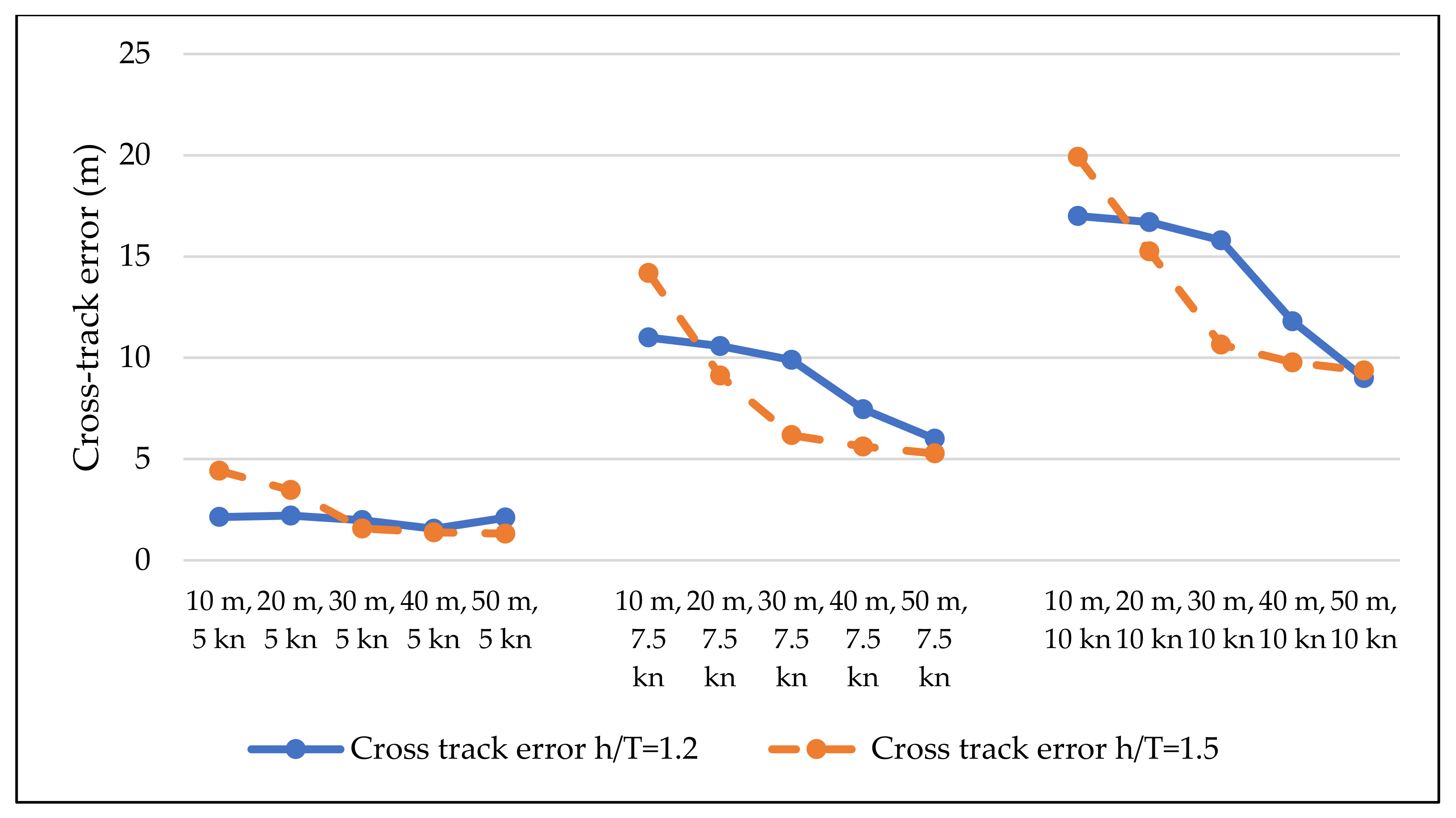
| h/T = 1.2T | h/T = 1.5T | ||||||||||
|---|---|---|---|---|---|---|---|---|---|---|---|
| Vessel Speed (kn) | Bank Slope | Ship Bank Sailing Distance | Ship Bank Sailing Distance | ||||||||
| 10 m | 20 m | 30 m | 40 m | 50 m | 10 m | 20 m | 30 m | 40 m | 50 m | ||
| 5 | 1:4 bank | 0.1 B | 0.1 B | 0.1 B | 0.1 B | 0.1 B | 0.1 B | 0.1 B | 0.0 B | 0.0 B | 0.0 B |
| 7.5 | 0.3 B | 0.3 B | 0.3 B | 0.3 B | 0.3 B | 0.4 B | 0.3 B | 0.3 B | 0.2 B | 0.2 B | |
| 10 | 0.4 B | 0.4 B | 0.3 B | 0.3 B | 0.3 B | 0.4 B | 0.3 B | 0.3 B | 0.2 B | 0.2 B | |
Publisher’s Note: MDPI stays neutral with regard to jurisdictional claims in published maps and institutional affiliations. |
© 2021 by the authors. Licensee MDPI, Basel, Switzerland. This article is an open access article distributed under the terms and conditions of the Creative Commons Attribution (CC BY) license (https://creativecommons.org/licenses/by/4.0/).
Share and Cite
Baric, M.; Mohovic, R.; Mohovic, D.; Pavic, V. The Simulation of Sloped Bank Effect Influence on Container Ship Trajectory. J. Mar. Sci. Eng. 2021, 9, 1283. https://doi.org/10.3390/jmse9111283
Baric M, Mohovic R, Mohovic D, Pavic V. The Simulation of Sloped Bank Effect Influence on Container Ship Trajectory. Journal of Marine Science and Engineering. 2021; 9(11):1283. https://doi.org/10.3390/jmse9111283
Chicago/Turabian StyleBaric, Mate, Robert Mohovic, Djani Mohovic, and Vinko Pavic. 2021. "The Simulation of Sloped Bank Effect Influence on Container Ship Trajectory" Journal of Marine Science and Engineering 9, no. 11: 1283. https://doi.org/10.3390/jmse9111283
APA StyleBaric, M., Mohovic, R., Mohovic, D., & Pavic, V. (2021). The Simulation of Sloped Bank Effect Influence on Container Ship Trajectory. Journal of Marine Science and Engineering, 9(11), 1283. https://doi.org/10.3390/jmse9111283