1. Introduction
Maritime transport accounts for 2.8% of the global greenhouse gases and pollutant emissions, which represents around 940 million [tons] of carbon dioxide (
) emissions annually, pollutant emissions being
equivalent for this estimation [
1,
2]. As a comparison, approximately fifteen of the biggest mega-ships alone account for as much pollution as 760 million cars. The main emissions of maritime transport are referred to
, nitrogen dioxides, sulphur dioxide, and particular matter. International shipping accounts for 87% of
emissions in shipping followed by domestic shipping with an 8% and fishing with a 5%, with an estimated grow expected by 2050 of 50–250% in emissions [
3,
4].
These increasing concerns related to the continuous use of fossil fuels in maritime transport activities have introduced the need for migrating from fossil fuel-based propulsion systems, towards different hybrid and all-electric propulsion system concepts, integrating alternative fuels from renewable energy sources (RES) having low and zero-carbon content. In this field of applications, the concept of Zero Emissions Ships (ZES) has gained great research interest. The most notorious ships in this group are ferries [
5].
The concept of Zero-Emission Ferry Ships (ZEFSs) has been introduced in the maritime industry. This concept consists of ferry consuming alternative fuels from RESs for service. Hybrid configuration of fuel cells (FC) and batteries is known as an efficient combination of clean energy devices for supplying the shipboard loads and providing propulsion power to ZEFSs. Energy produced by FCs is utilized as the main energy resource while batteries can be used to respond to the fast dynamics of the loads that FCs are not capable to cover [
6]. Moreover, energy from photovoltaics (PV) and cold ironing at the harbours can be considered as auxiliary resources along with an optimal energy management system to improve the efficiency of these ships.
However, when extrapolating the ZEFS configuration into larger ocean-going ships, several technological and logistic challenges arose, such as: energy density, weight of these devices, power conditioning, time underway, and port interface support, which must be taken into consideration, before its implementation. In this field of applications, hybrid propulsion systems exhibit many advantages, but a concern referred to ensure a complete reduced emission operational profile.
This work discusses the advances and new trends in marine propulsion systems and auxiliary systems, focused on the challenges towards the development of a ZES propulsion systems and a zero-emissions shipping.
2. Zero-Emissions Ship
The challenges to achieve a zero-emissions ship (ZES) start from getting a clear definition of emissions. The most common definition relates the release of something to the environment, being a product and/or a by-product from an energy source. The current shipping energy source is based in fossil fuels and the conversion technologies to get the energy content based in thermal processes associated with thermal machines. Product and by-products of these processes are work and exhaust gases. The focus of the work is to get ships navigating fulfilling different operational profiles most efficiently and exhaust gases are the wasted energy, respectively. The efficiency means fulfilling the operational profiles consuming minimum amounts of energy. The operational profiles considering not just navigating from one point to another but also including the operation at berth and port interaction of cargo handling. The main propulsion system and the auxiliary systems supporting it and to support the general services of the ships need to be included.
Energy sources based in fossil fuels are presented in
Table 1 along with the conversion technologies based in thermal processes commonly found in current ocean-going ships. This is just a list and no details regarding a specific combination of fuel and technology are considered. Taking the definition and considering the energy source and the thermal process associated, it is possible to fully define and understand the by-product exhaust gases as the emissions from shipping. These emissions can be segregated into two main groups, greenhouse gases (GHG) and pollutant emissions (PE).
Table 2 presents these emissions including those not produced by the technologies presented in
Table 1 but produced by auxiliary systems and consumables used to keep the general services of the ship such as refrigeration, cargo handling, and maintenance systems. The formation and the quantity of emissions depend on the quantity of fuel consumed and the technology associated. The more efficient the consumption, the lower emissions generation.
The real challenge to achieve a ZES is to replace current fossil energy sources along with the technologies associated with their consumption but not just for the main propulsion system also considering the auxiliary systems and consumables. Taking fuels, technologies, and emissions presented in
Table 1 and
Table 2 as a baseline, it is possible to start selecting new energy sources and technologies to replace them. It is even possible to consider alternatives to retrofit existing technologies aiming to start to propose and define concrete options to achieve a ZES.
The IMO through the Initial IMO Strategy to Reduce GHG Emissions [
7] helps to identify some of the new energy sources and technologies available and under research to canalize the efforts of getting a true ZES. The strategy considers the application of short-term, mid-term and long-term measures to reduce firstly and to eliminate further emissions from shipping. The development of a ZES needs to consider options to retrofit existing ships because the replacement process, in quantity and just more efficient ships of the current fleet, is not enough to overcome the inefficient existing ocean-going fleet, which is almost complete based on the consumption of fossil fuels [
5].
Table 3 presents the measures, the timeline, and a reproduction of some of the technologies identified as the most suitable to achieve a ZES from the Initial IMO strategy.
The energy efficiency design index (EEDI) is a technical measure established and mandatory by the IMO for every new ship built from 2013 ensuring efficiency baselines that new ships need to meet [
8]. The energy efficiency existing ship index (EEXI) is a new regulation coming from the IMO to know the operational efficiency of the current fleet by establishing a baseline of the actual efficiency from where to start working to improve the efficiency by the application of technological and operational measures [
9]. The carbon intensity indicators (CII) are tools to measure the actual efficiency of an existing ship and works in tandem with the EEXI to ensure that existing ships efficiently perform considering the application of technological and operational measures to further improvement [
9]. The ship energy efficiency management plan (SEEMP) is an operational measure acting as the interface between the administration and the operation of its ships establishing protocols that consider the measure, control, mitigation, and improvements of the efficiency over time [
10]. The rest of the technologies presented in
Table 3 can be correlated to the EEDI, EEXI, CII, and SEEMP because their application is evaluated by these indexes, indicators, and plan. Shoreside power supply (SPS) or cold ironing from RESs consider the interface between the port and ship activities, which is quite important because emissions generated affecting the port cities and coastal areas need to be reduced as well. These emissions, especially the pollutants, notoriously affecting human health [
11,
12].
Considering the dependency of energy from fossil fuel sources of the existing fleet of ocean-going ships, its emissions and the technological and operational measures of efficiency established by the IMO seems reasonable to get a ZES. This is achievable by changes in the technology currently applied in the main propulsion and auxiliary systems by considering alternative fuels as energy sources with a zero-carbon content.
For the development of full electric propulsion systems based on auxiliary systems supplying the required electric power for the ship, running on alternative fuels has been addressed as the path to follow to achieve a new ZES. This path to be applied to existing ships as well as part of a process of hybridization of the propulsion and auxiliary systems reducing the impact of emissions due to shipping. Full electric and hybrid ships are already in service but limited to a certain type and size, creating a necessity to understand the reasons of its lack of applicability to new and existing ocean-going ships.
3. Full Electric Propulsion System
The Full Electric Propulsion (FEP) system consists of an arrangement, where the ship’s prime mover is an electric machine in a direct drive configuration, directly connected to the main propulsion shaft, without using a gearbox. In this configuration, electric power is provided by a certain number of generator sets (genset) commonly driven by thermal based machines such as gas turbines, diesel engines, or a combination of both. Gas turbines, such as genset, related to existing old LNG tankers have the capacity to use the boil-off gases of its cargo as the fuel for its service, new LNG tankers using dual fuel diesel engines [
13]. Depending on its structure, the electric propulsion systems can be classified as segregated or integrated [
14,
15].
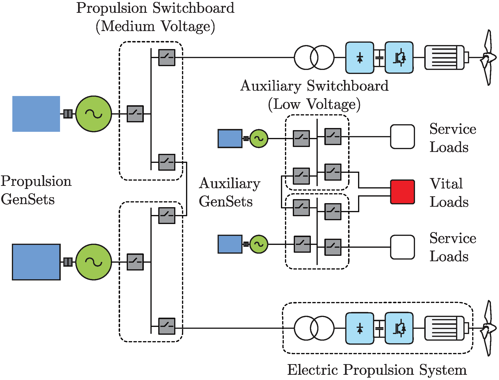
3.1. Segregated Configuration
The segregated FEP can be understood as the natural evolution of conventional propulsion systems, by replacing the main combustion engines with low speed electric machines, usually multi-pole machines, resulting in two segregated electric distribution systems: one dedicated to providing the required power for the propulsion system and another dedicated to supply the required power to the ship’s auxiliaries, which is already part of the original ship configuration.
Figure 1 shows a typical segregated FEP configuration.
In this configuration, about 90% of the total generation installed power is dedicated to the electric propulsion drive. This arrangement becomes very attractive for those applications where high manoeuvrability and thrust are required, such as icebreakers and towing ships [
16]. Despite this operational advantage because of the ship’s operational profile, propulsion gensets operate in an underrated condition, with the consequent increase of emissions. Moreover, the remaining available power in the propulsion system is not available for the ship’s auxiliaries because of the nature of this configuration, regarding power management flexibility and availability.
3.2. Integrated Configuration
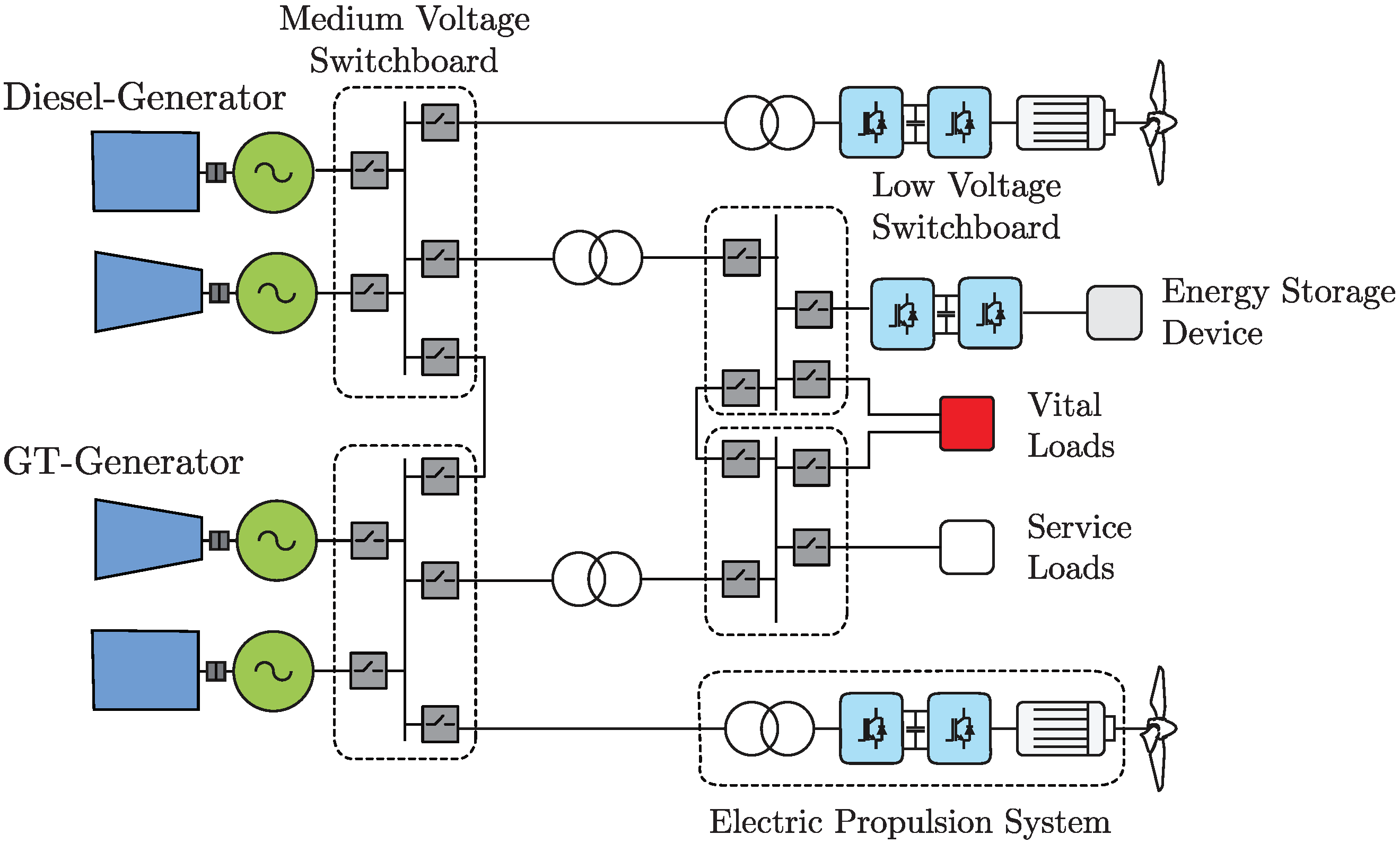
The integrated FEP is the next evolution of new propulsion systems design. This concept considers that all the required power for propulsion and the ship’s auxiliaries is to be supplied by the gensets depending on their power capacity.
Figure 2 shows a typical integrated FEP configuration.
In this configuration, the gensets feed a single busbar or switchboard in the medium voltage range. Electric power for the propulsion system is fed directly from this busbar by means of power converters, which use an active front end to condition power quality and enable the regeneration during speed dynamic breaking and manoeuvres. This recovered energy could be stored in batteries, supercapacitors, or other similar devices, to be available during fast dynamic response speed and thrust transitions. The ship’s auxiliaries, on the other hand, are fed from the main busbar, the medium voltage switchboard, using step-down power transformers.
The most remarkable characteristic of integrated FEP is referred to its capability of ensuring high flexibility, availability, and system redundancy. The total demanded and available power are managed using an energy efficiency optimization strategy, which defines the number and capacity of the gensets to be in operation in the most efficient operation point of their maximum continuous rating (MCR), thus enhancing fuel efficiency and reducing emissions [
17,
18].
4. Hybrid Propulsion System
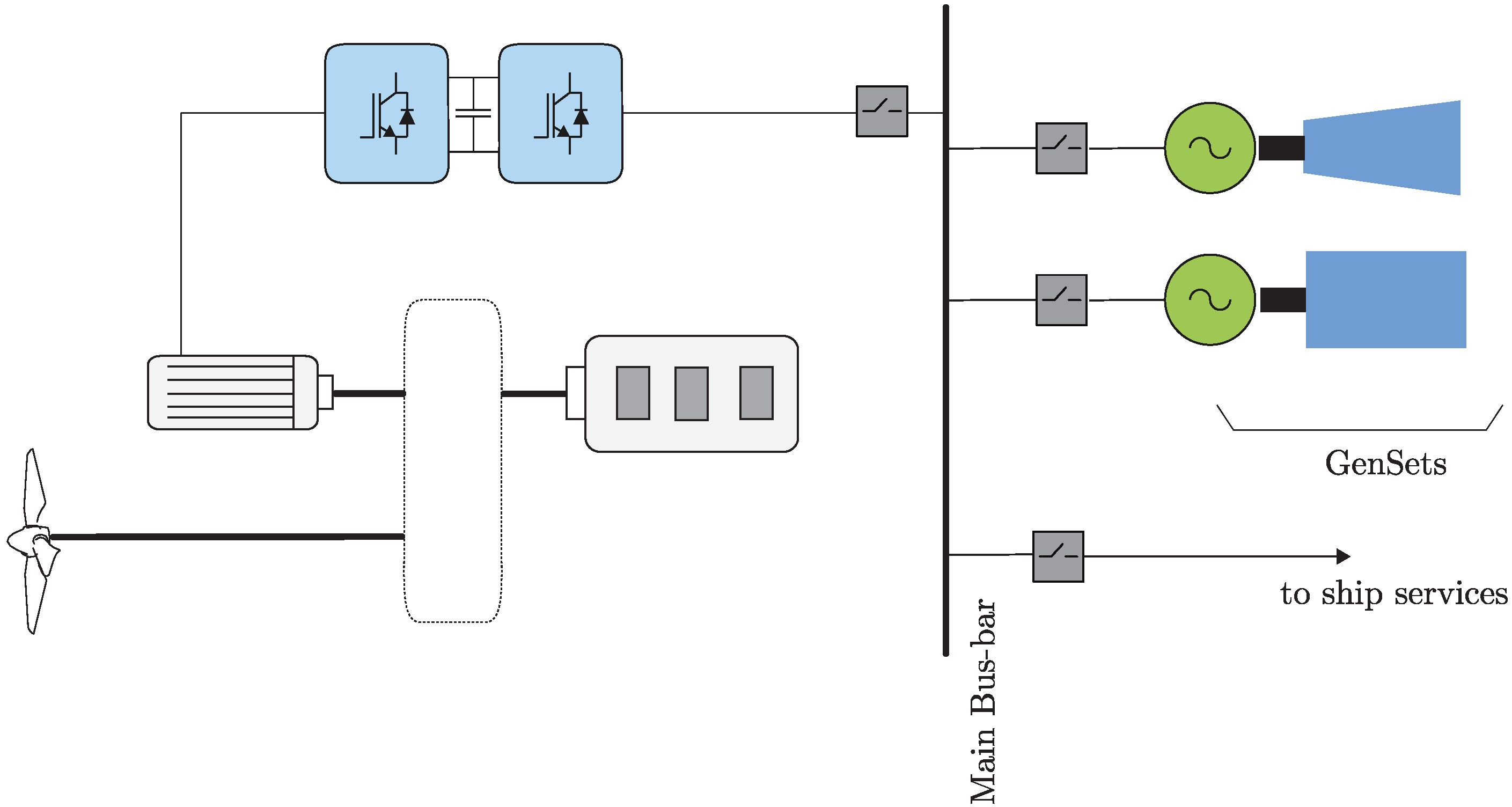
A Hybrid Propulsion System (HPS) is the combination of a conventional thermal based system with an electric propulsion system working either in parallel or in series, as shown in
Figure 3. It is a well-known configuration applied either to existing or new ships. The conventional part of the HPS usually considers the use of a diesel engine as the driver, which is connected through a transmission system, usually a shaft, to the propulsor. The propulsor is usually a propeller, which can be a fixed pitch propeller or a controllable pitch propeller. The electric part of the HPS considers the use of an electric motor as the driver connected to the rest of the propulsion train system. The HPS introduced to support the variability of the operational profiles of some type of ships such as tugboat, ferries and supply vessels as the most notorious [
19,
20].
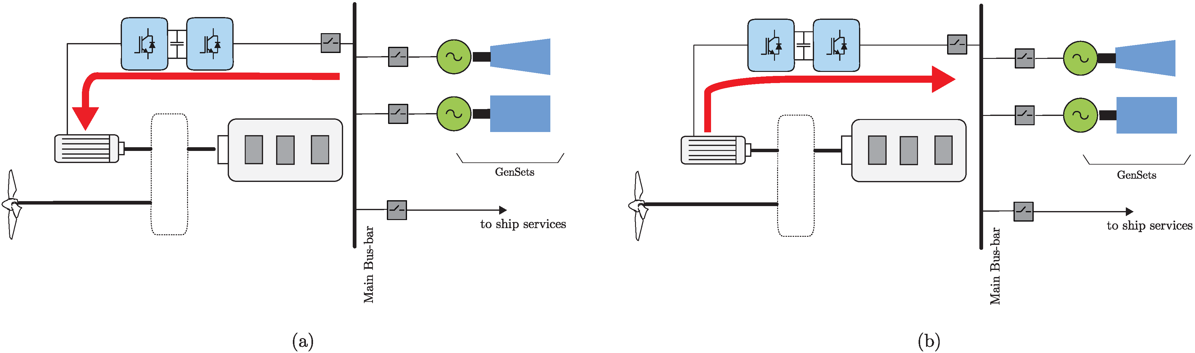
In this propulsion system configuration, the electric drive can operate either as a motor, power take-in mode (PTI) or as a generator, power take-off mode (PTO) as shown in
Figure 4. In PTI mode, the electric drive provides the required propulsion power, where the energy is provided by the gensets, allowing the thermal based engines to remain shut down. On the other hand, when operating the thermal based engines for long periods in their low power range, the electric drive can be set to operate in PTO mode, taking advantage of the remaining power that could be provided by the thermal engine, supplying the main electric busbar. Being in PTO mode enables the possibility of reducing the number of running gensets, thus reducing emissions, by moving their operation point, towards the optimal fuel efficiency range. The HPS offers many benefits over conventional thermal, including efficient operation of thermal based engines at low ship speeds, additional power for auxiliary systems, and an efficient power dispatch for the gensets [
16,
21].
Having the ability to work either in parallel or in series allows for the system to support fluctuate ships’ operational profiles. Attached to an efficient Energy Management System (EMS), this configuration takes the best performance of the drivers either at low or heavy loads, keeping the whole system efficiently operated as well [
22].
The challenges of this configuration are related to the drivers and the EMS. The drivers to work either in parallel or in series need a transmission system robust enough to allow the switching from one to another or keep them both working at the same time in a fast and secure way. The transmission system needs to keep the ship continually performing reliably.
This system is a combination of gearboxes and clutches, which relates mechanical efficiencies related to the drivers’ efficiencies that make the whole system an intrinsic dependency of performances. The better the performance of the driver, the better the performance of the whole system. In this sense, the diesel engine part is the most challenging system to be considered when developing an HPS. The performance of the diesel engine is most efficient around 75% and 85% of MCR [
22], having the lowest specific fuel-oil consumption (SFC). Moving from these percentages, either to low or high loads, increases the SFC and thus the emissions. The EMS needs to overcome the performance of the diesel engine allowing for the PTI to enter into service to complement its performance. The EMS becomes a challenge because it needs to have the capacity to estimate at which point the performance of the whole HPS is most efficient keeping either the mechanical and/or the electric part of it performing.
The EMS needs a robust and reliable control system to keep the individual performances of the drivers and also the energy needed and distributed over the performance of the ship fulfilling its operational profile.
The HPS applied to a new ship takes the considerations presented embedded into a reliable EMS and rigorous analysis of the operational profile of the ship. The gain in efficiency of the HPS applied to new ships has been reported when comparing similar ships [
20]. Applied to an existing ship is completely different and the most challenging because it needs to consider the actual performance of the ship, which is related to energy efficiency and economical evaluations without forgetting its life-cycle. The improvements in efficiency need to be compared against the performance of similar ships or over time, which is a complex task when considering that ship’s performances depend on external factors such as weather and routing [
23,
24].
When considering an FEP and an HPS, new technology arises, which can still consume current fossil fuels but alternative fuels as well. Technology associated with the propulsion and auxiliary systems consider the development and application, either for retrofitting existing ships and for new ships, of fuel cells, batteries, supercapacitors, and dual-fuel engines—the latest to be applied either to the main and to the auxiliary system as the main driver and as part of the gensets.
4.1. Fuel Cells
A Fuel Cell (FC), as a technology application, is an option to be implemented in FEP and HPS because it eliminates emissions and noise while producing the required electric power. Associated with the consumption of zero-carbon fuels such as
and
, a fuel cell converts these fuels into electricity generating heat and water as by-products [
25]. The electricity to be used is either by the main propulsion or the auxiliary systems. Two types of FCs are used on board ships, proton exchange membranes, or polymer electrolyte membranes (PEM) and solid oxide fuel cells (SOFC). PEM is already in use on board ships such as ferries, passenger vessel, and navy applications [
25,
26] with research behind later applications from early 2000 [
27,
28,
29]. SOFC is still in the development stage to be applied on board, despite the high readiness level of it [
30] and research behind it [
31,
32]. The application of PEM FCs on board ships considers the establishment of a fuel cell’s stack connected to the ship’s grid to provide the required electric power demands either for propulsion or for ship’s auxiliaries. The current application range of PEM stacks on board ships is up to 6 MW [
33].
PEM stacks into FEP configuration and replaces the conventional means of electric power generation allowing for obtaining a zero-emissions system. The same replacement occurs in a HPS but the conventional part of the system, keeping the ship generating emissions. Unless the conventional part of a HPS is replaced, the efficiency of using PEM stacks is wasted if a ZES wants to be achieved. Only fuel cells for new ships and retrofits to FEP systems can be considered. The current readiness and scalability of PEM stacks allow for considering its use in ocean-going ships but keeping in mind the requirements of storage of the fuel consumed. It seems that there is no challenge when considering the capabilities and electric power generation rate of FCs but is not possible to consider its application without analysing and evaluating its fuel type and consumption. How much fuel relates to the storage/energy density and the risks to be used on board become the real challenges rather than the PEM stacks application. Current ships having FCs applications are restricted to inland navigation using waterways such as rivers, canals, and bays only. This restriction allows for obtaining a well-defined fuel supply chain securing enough refuelling capacity and reducing the on-board storage capacity is deemed to be the challenge when estimating the fuel consumption of using FCs. The autonomy of these ships is limited yet enough to fulfil their operational profile, which is mostly to transport passengers and vehicles [
26].
4.2. Dual-Fuel Engines
A dual-fuel engine (DFE) is an engine that can work under the Otto cycle and the Diesel cycle. When working under the Otto cycle, it burns gaseous fuels and, when working under the Diesel cycle, it burns liquid fuels [
34]. A DFE from origin is the kind of engine considered to be fitted in new ocean-going ships [
5] because it allows for obtaining more fuel options to be used for services’ operations and to comply with IMO regulations regarding sulphur content and Emissions Control Areas (ECA) [
9,
35]. This DFE can be used either for propulsion or as gensets.
The technology behind this type of engine considers the configuration and adaptation of the fuel system to be switched from one fuel to another in a reliable way, securing the ability to keep the ship’s power demand for service. One of the challenges of using DFE is to make the decision of which fuel to use. Gaseous fuels such as LNG, LPG, and syngas are available having a lower carbon footprint. Liquid fuels such as current fossil fuels, HFO, LS/VLS/ULSHFOs, MDO, LPG, and CNG along with alternatives fuels having a lower carbon footprint such as biodiesel, methanol, ethanol, butanol, compressed , and compressed are available.
Fuels such as NG,
, and
when compressed can be used as liquid fuels. One of the challenges of considering these liquid fuels to be used by DFE is the storage based in their energy density, which in fact is a challenge for every alternative fuel when compared to current fossil fuels. Details regarding alternative fuels challenges are going to be developed in the next section.
when burned in this engine generates by-products [
36], and limiting its consideration to get a ZES yet from a transitional perspective is an option to reduce emissions from shipping.
Another option regarding DFE is the retrofitting of existing single fuelled engines to use different liquid fuels, different gaseous fuels, and the use of one liquid and one gaseous fuel. The technological readiness level of retrofitting existing engines is quite mature and has been applied to existing ships since 2000 [
37,
38]. The applications reaching and exceeding the power needed by the largest ships already in service [
5]; therefore, no technical challenge can be found to switch to a dual-fuel configuration.
The review of these, not new, technologies in the context of a HPS configuration showed that there is no technology limitations for them to be applied on board ocean-going ships. There is enough capacity to deliver the power, either for propulsion or for auxiliaries, to fulfil the operational profile of an ocean-going ship. In general, it is expected to develop a technical assessment of safety elements to connect these technologies because it implies making modifications of the ship’s fuel storage capacities, and to the existing machinery as well. Perhaps the scaling of sizing current technology could be considered as a challenge, but this is inherent in any project, either a retrofit or a new ship and thus an integral part of the technical assessment, which is not limited to just safety but also to capacities. The capacity based on the energy density of considering new alternative fuels becomes the real challenge, and it is reviewed and discussed next.
5. Alternative Fuels
An alternative fuel is a different fuel from current fossil fuels considering its carbon content. Two groups can be defined: first, alternative fuels having a low-carbon content and, second, alternative fuels having zero-carbon content.
Table 4 presents some of the main general characteristics of current available alternative fuels for comparison. In the low-carbon content group, just considering the carbon factor and content, methanol and ethanol are the notorious fuels reducing the
footprint. Nonetheless, for the scope of getting a ZES, the use of these fuels helps to reduce the emissions generation from shipping. Biofuels enter this group but were omitted from
Table 4 just because of the large pallet of options currently available [
25].
In the zero-carbon content group, both and are feasible options to be used to get a ZES. This is independent of the technology associated with obtaining their energy for the ship being just a fact based on the no carbon content of it, which, for this review, allows for obtaining a general view of changing current fossil fuels for these alternative zero-carbon fuels.
Early reports from the IMO, Classification Societies, and the IEA have showed that less than 2% of the total mix of fuels consumed by the shipping industry correspond to alternative fuels [
4,
9,
25]. This low consumption is related to their low availability and demand. However, regarding the capabilities of these alternative fuels to support and help decarbonize the shipping industry, their applicability on board is a task not just related to the bunkering process but to the whole supply chain. The availability of these alternative fuels considers their use in industries different from shipping, which means that, for shipping, more production is needed, a challenge to overcome not just for a ZES but for the whole shipping industry.
It seems impossible not to connect this availability and the technology associated with the Initial strategy to reduce GHG and Emissions from the IMO. The establishment of regulations to apply this mix of alternative fuels and technologies clearly shows that, to reach a ZES, a transitional process moving from current fossil fuels to zero-carbon fuels is needed. The process involves the use of low-carbon fuels in early stages of applicability to new and existing ships considering current technologies and the process mandated by the IMO to monitor and evaluate its impact over time. An example of this is the coming regulations from the EU regarding the application of low-carbon fuels to ships navigating in EU waters by 2030 [
39], which is a clear statement to reach a full decarbonized shipping industry as declared by the IMO [
7].
5.1. Hydrogen
This zero-carbon fuel, also considered as an energy carrier, can be produced by reforming fuels and by an electrolysis process [
25]. Both need a great amount of energy. Depending on which energy source is used for its production,
gets different notations such as brown, blue, and green as the most common nowadays. Brown and blue denote the use of energy sources from fossil fuels producing a
with a
footprint. Green
means the use of a RES such as wind, solar and hydraulic to produce the electric power needed for its production, eliminating its
footprint.
It is important to notice that only the instant production process approach is considered to get these notations. When considering a global approach, which means the whole productive process including the production of the technology related to the processes, a footprint can be estimated. The footprint of the whole production process can be considered as a challenge. If the immediate goal of getting a ZES is desired, this could not be a challenge because the quantitative result is a ship not generating emissions.
As a fuel,
have a high energy density and can be consumed by FCs and engines on board ships yet applications have been limited to small ships such as recreational and ferries since 2007 [
26]. The storage capacity and autonomy of these ships is quite limited compared to an ocean-going ship but works because secures a bunkering network across the routes to keep them operational without disruption. Ocean-going ships are designed with a high storage capacity to ensure maximum autonomy to fulfil their operational profile without disruption. Considering the properties of
in terms of energy density compared with the rest of available alternative fuels is easy to understand why is so keen to be used in ocean-going ships. The drawback of this comparison relates the volume needed to storage, which in accordance with
Table 4 requires more than 4 times compared to MGO, which is something difficult to overcome for any ship. Is this a challenge? design processes involve rather than technical challenges, technology to storage includes pressurized and cryogenic tanks with a high level of readiness to be applied on board ocean-going ship [
37]. It seems that
availability in quantities to support the demand to cover the operational profile of ocean-going ships is the challenge along with a bunkering network with capacity to cover different and long routes.
5.2. Ammonia
This zero-carbon fuel is less energetic compared to
and can be consumed by FCs and engines as well. Engine manufacturers developing an engine working under the Diesel cycle capable to burn
to be commercially available between 2022 and 2024 [
37,
38]. In FCs,
can be quite corrosive when considering PEMs limiting its use in SOFCs but from where high power density up to 2 MW could be reached [
30]. Perhaps the only problem with this SOFCs is the high operating temperature, between 500 °C and 1000 °C, which is quite a high range compared to those working temperatures found in current ocean-going ships, and this could be considered as a challenge because it implies the use of a more efficient and robust cooling system or perhaps a Waste Heat Recovery System (WHRS) to regain some of this heat. The latest challenge could become an advantage, yet no information of ships’ applications has been reported to explore this option; however, research showing the alternative could prove to be valuable for further revision [
40]. Projects regarding ships fuelled by
using SOFCs were found but without many details to quantitatively explore and perform a more comprehensive analysis [
41].
Storage capacity, as per
, limited its applicability in ocean-going ships even though, when considered as cargo, it could be used in the same way as LNG. This principle is only based on the characteristics of
transported in chemical tankers, which is a well developed process and safe under the IMO [
42]. No references were found to develop this option, but it is something to look up when considering the readiness level of the
transport in existing tankers besides the quite well developed infrastructure to load/unload
.
Particular attention, when reviewing
as a fuel, was made to Classification Societies. These Societies provide the notation of “Ammonia Ready” to new ocean-going ships. The particularity of these ships is the consideration of DFE for the main and auxiliary engines besides structural characteristics for the storage tanks [
43,
44]. DFE with the capacity to burn current fuels and LNG as an alternative fuel. The ammonia notation allows for switching from LNG to
when available.
Considering the declarations from engine manufacturers regarding the development of new engines burning
, the notation given to new ocean-ships from Classification Societies and the well know process of carrying
, seems reasonable to infer that is no technical challenge ahead of getting an ocean-going ship running on
, this is just a matter of time. This is not a ZES on
because the combustion process of it still generating
emissions [
34].
5.3. Transitional Fuels
This group of fuels includes MGO, LNG, LPG, Methanol, Ethanol, Biofuels and the nearly new so called electrofuels or e-Fuels. The latest are based on the use of renewable energy sources for its production and considered as carbon-neutral fuels [
25]. These fuels having a low-carbon content, meaning that emissions are less compared to the use of current fuels such as HFO and LS/VLS/ULSHFOs. Some of these fuels significantly reducing
,
, and
, which are deemed to affect port areas and coastal cities the most [
11,
12,
45,
46].
These transitional fuels are the bridge between current fuels and zero-carbon fuels—considered in this way because they can be used by most existing ocean-going ships after a technical assessment, which means a comprehensive analysis of how much the efficiency will improve without forgetting the safety and economical aspects, availability, and IMO mandatory compliance. The latest includes evaluation of the SEEMP, EEDI, EEXI, and CII because there is a direct relation between reducing the emissions over the life-cycle of the ship. GHG and EP besides
are considered through an estimation of getting a
equivalent or
to quantify the real impact of shipping over time [
47].
The technical assessment includes retrofit options but keeping in mind that, unless the retrofit is to a FEP, the ship still cannot be considered as a ZES. These transitional fuels help to reduce emissions from shipping overall, keeping the shipping industry operative moving towards a zero-emissions shipping.
In general, when mixing HPS technologies with alternative fuels, a technical assessment of safety elements is necessary to develop, in the same way as for the technologies, to truly connect these alternative fuels. This implies, besides the modifications of the ship’s fuel storage capacities, and to the existing machinery, a financial assessment of fuel conversion costs. The assessment includes and cannot be limited to the investment in the technology associated with the existing machinery, the costs of these alternative fuels plus the maritime shipping costs without forgetting the ship’s life-cycle [
48].
6. Energy Storage Devices
The use of Energy Storage Devices (ESD) such as batteries and hybrid battery/super-capacitor configurations is meant to be used as an alternative to the installed gensets to support the generation and distribution of electrical power. When going into the HPS concept, as described previously, gensets are assisted by ESDs [
49,
50,
51], improving the stability and availability of the propulsion system by reducing the voltage variations. These devices are also used to optimize the fuel consumption to minimize costs and emissions, by strategically controlling the load of the gensets during transient operation, according to a reference model [
52].
ESDs have been improved during the last few years, in terms of their capacity, functionality, and regulations, allowing them to be used as a spinning energy reserve. For this purpose, ESDs must be compliant with several requirements:
Dynamic performance: when getting the gensets into load, it should be gradually ramped up because increasing the load too quickly might lead to a system blackout due to the unbalance between the active and reactive power flow. In this field of operation, ESDs can supply the required power, in a short time rate during these load steps, thus permitting an accurate balance of active and reactive power.
Peak shaving: ESDs can supply the required power to overcome voltage peaks and sags, which occur during the starting and stopping of electric machinery, thus stabilizing voltage and preventing damage of the service and essential ship loads.
Spinning reserve: for redundancy purposes, ships can run with fewer gensets supplying the main busbar, by moving the load per genset towards the optimal fuel efficiency point and thereby reduces the fuel consumption and emissions.
Zero-emissions operation: under some operational conditions, it may be possible to shut-down the gensets and supply the electric power demands from large ESDs, leading to a zero emissions operation. This requirement has become a very interesting goal for the development of future ZES and port operations.
ESDs are commonly connected to the main busbar via an active front-end power converter, thus enabling the ESD to operate in floating mode for the stand-by condition and the supply power when required to the busbar. To ensure this operational profile, an EMS is required to supervise and control the power flow, on the base of the instantaneous power demand, the number of on-load gensets, their MCR, and the stored energy in the ESD.
DC-grids are another alternative of integrating ESDs to the ships busbar, reducing the size and costs of power electronic devices and ensuring a stabilized voltage operation, which is vital when considering the life indicators of ESDs. Another important improvement is the increased efficiency of gensets by operating in variable frequency mode, which allows for decreasing the engine speed at low loads, thus reducing emissions.
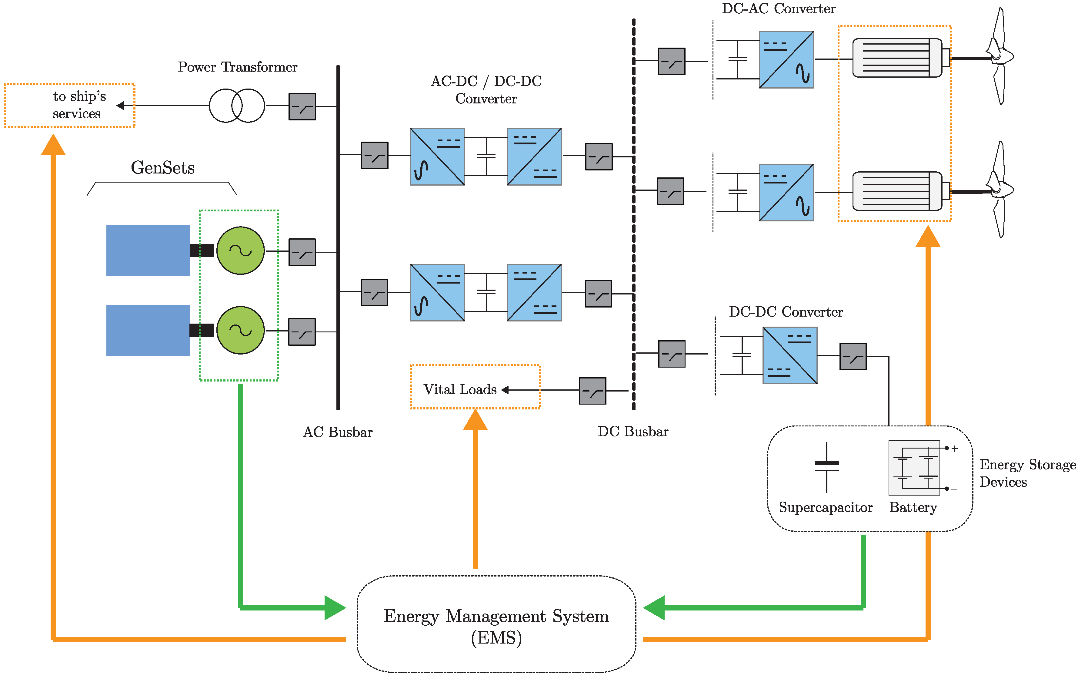
Figure 5 shows an IEP system configuration, integrating ESDs such as batteries and supercapacitors.
The electric power distribution system consists of both AC and DC busbars. The last one provides the interface for the incorporation of the ESDs into the ship’s power grid. The electric propulsion motors are fed directly from the DC busbar, thus reducing the complexity of the requited propulsion power converters. An AC-DC conversion stage linking both AC and DC busbars ensures full control decoupling and voltage stability in the DC busbar. Power flow is supervised by an EMS in order to optimize the operation of the gensets, thus reducing the emissions.
6.1. Batteries
Nowadays, the high costs of batteries make their lifetime a very important parameter to take into consideration, when defining the size of an ESD. In this aspect, some limitations must be considered, to maximize the battery lifetime, such as:
State of Charge (SOC): as the ratio of the available charge capacity and the maximum possible charge that can be stored in the battery.
State of Health (SOH): considers the capacity loss in terms of the remaining capacity in aged batteries compared to the nominal capacity of a new battery.
State of Function (SOF): as an indicator which evaluates the continuous and instantaneous load capability of a battery.
Depth of Discharge (DOD): as the percentage of battery capacity that has been discharged, expressed as a percentage of maximum capacity.
Life-Cycle: as an indicator of the charge-discharge cycles that the battery can experience before it fails to meet specific performance criteria. Life-cycle is estimated for specific charge and discharge conditions. The actual operating life of the battery is affected by the rate and depth of cycles and by other conditions such as temperature and humidity. The higher the DOD, the lower the life-cycle.
Considering the high cost of batteries, their lifetime is a very important parameter to be taken into consideration. Subsequently, to increase the battery lifetime, their application is limited to several types of ships. In the case of ferries and coastal cruise ships which have short voyage times, the ESD based on batteries is a suitable power source because the DOD is not so high, ensuring the battery lifetime. In the case of tugs and dynamic positioning vessels that require high electric power for a short time, the ESD can be used for a limited time in response to peak operations ensuring battery SOF. Furthermore, the ESD has becoming a main power source replacing conventional gensets into small coastal ships [
26]. For an oceangoing medium-sized merchant vessel, which requires megawatt (MW)-class electric power, it is not easy to totally replace the main power source from gensets with an ESD. Therefore, the combination of the ESD with the installed gensets is the only solution [
53,
54].
In addition to the above referenced constrains, the time at berth needs to be considered when using battery based ESDs. In this concern, recharge time is a key factor, which will depend on the SOC, SOH, and DOD of the battery.
Table 5 shows the typical time spent at berth of different ship types as a reference [
55,
56].
6.2. Supercapacitors
Supercapacitors (SCs) or Electric Double Layer Capacitors (EDLC) are high power density ESDs that have gained huge research interest in the last decade towards their application in electric vehicles and renewable energy conversion systems, as the natural evolution of batteries. In this respect, as presented previously, besides batteries being a very well-known and developed technology, they have several drawbacks, such as: a low life-cycle which limits their recharge capability and long recharging time, which appears as a major concern for marine applications, and low power density [
57,
58,
59]. SCs, on the other hand, can provide and recover to storage a high amount of power in a short time, during voltage sags and regenerative breaking conditions. Some performance parameters must be considered when considering SCs as a technological solution for large vessels:
Capacitance: as an indication of the energy storage behaviour of the SC, which is a function of the operating voltage and frequency. This is an important aspect to be considered; thus, it can represent a 15–20% variation in the SC rated energy storage capacity.
Aging: related to the degradation of the SC internal chemical and physical layers, affecting their capacitance and charging/discharging dynamics. However, in this aspect, it must be mentioned that the degradation process due to cycling operation or cycling aging is more significant than the degradation due to time aging.
Self-discharge: this effect is due to the leakage of current, which is established between the electrodes of the SC. This leakage current is a consequence of the electrostatic phenomena that take place at the electrode surface of these kinds of storage devices. The self-discharge time of an SC depends mostly on the actual device voltage, operational temperature, and aging.
Compared to batteries, SCs have many advantages, such as: higher power density and a wide range of operating temperature, although both present the effect of cycling aging, but, in SCs, it is less significant, which make them very suitable for smoothing voltage gaps and sags, and to recover energy during regenerative breaking, due to emergency manoeuvring for a few seconds. On the other hand, because of their low capacitance, the discharge cycle is too fast to consider their use as voltage stabilizing or emergency voltage source for vital machinery. In this context, SCs will be preferred to batteries for applications where high power, low energy, and large cycling requirements are demanded.
7. Toward Zero-Emissions Ship
ZESs are becoming increasingly viable in several settings for short-sea shipping applications. The use of FEP along with zero-carbon fuels seems to be the only feasible current alternative. Battery-electric ferries have been deployed in several countries in Europe and appear to be poised for expansion. Although batteries appear to be the most cost-effective option for this application, FCs ferries are also in development. Batteries and FCs both represent feasible and compelling options that offer ZES. However, cost and weight of batteries, fuel costs, and storage difficulties for are currently limiting the scalability to commercial implementation as a solution to get an ocean-going ZES.
For larger ocean-going ships, such as container ships and tankers, the transition to zero emissions remains much more challenging. The low energy density of energy storage devices, such as batteries and SCs, makes this technology not viable as a main power source because of the extremely long voyages between recharging/refuelling. Storing for long voyages, in a compressed or liquid form, requires substantial modifications in the ship design, safety measures, and regulations.
and other gas stage alternative fuels have been proposed as an attractive alternative in terms of storage and energy density, but these solutions are still under research and development. implementation to be burned in thermal based machines is under development as well without forgetting that other emissions can still be generated. Additionally, the relatively high efficiency of actual fossil fuels based marine engines and the low cost of associated fuels, especially HFO and LS/VLS/ULSHFOs, make operational costs of these new technologies unattractive. However, moving from current fossil fuels to these zero-carbon fuels implies the development of drivers and gensets with the capacity to handle them. Technology able to handle these fuels was presented, and the challenges were clearly stated. It is not just about to change the fuel also to the development of a technical assessment to get the implications considering the life-cycle of ships. The ZES seems like a process instead of just something to be done.
Another important issue to take into consideration is the upgrading of ports to bunker alternative fuels, including cold-ironing capability for high-power battery charging. In this context, financial support and local policies are critical aspects to consider accelerating the transition in these sectors to drive down the costs of these new technologies—without forgetting the role of ship owners and port authorities when applied.
Going for HPS configurations appears as a short-term high reliable solution for the currently operating fleet. The capability of using ESDs, in combination with thermal based machine operating with alternative fuels, can provide fuel efficiency operation, with the consequent reduction of emissions. In general, some challenges were found, but they are on their way to be overcome when early adopters make the decision to improve the efficiency by applying these options.
Retrofit of existing ocean-going ships is a task involving not just the shipowner but also the shipyard, which means a process of availability, scheduling, and lay-down period to name a few. This task needs to oversee the new building and scrapping of old ships adding an extra consideration to aim for. The renovation and scrapping of the existing fleet involve the whole shipping industry chain and cannot be avoided in the analysis of achieving a ZES. It seems reasonable to draw a line; even if the shipping industry starts building ZES from now, the renovation is not going to be enough to make the existing fleet converge into a ZES fleet before 2050 as IMO requires and mandates [
7]. The ratio between the existing fleet and the new ZES needs to be calculated. This analysis needs to be worked on and is going to be part of the future work in order to get a deep understanding of the challenges to get a zero-emissions shipping based on ZES.
8. Conclusions
Technological challenges to get an ocean-going ZES consider the following:
The development and scalability of the machinery, for main and auxiliary systems, based on an electric configuration instead of using conventional thermal based machinery.
The retrofit of thermal based machinery of existing ocean-going ships considering their life-cycle. A technical assessment is necessary, which means considering economical aspects.
The low ratio between the renovation and scrapping of the existing fleet against new ZES.
Alternative fuel challenges to get an ocean-going ZES consider:
Especially for and , to consider the storage capacity and the use in electric rather than thermal based machines because it is the only option to avoid the whole spectrum of emissions that the combustion process of the latest generates.
Get the existing fleet to swoop to low-carbon fuels when the availability is still uncertain.
Avoid, reduce, and mitigate the whole spectrum of emissions that the combustion process, in current single and dual fueled engines, generates.
Energy Storage Device challenges towards ZES consider:
Life indicators, which will limit the number of consecutive charge-discharge cycles, and will limit their maximum stored energy capability.
The power electronics interface and power managing system to ensure operation of the thermal based machines within their minimum emissions operation point, and maximum stored power availability.
Upgrading of ports, to ensure cold-ironing interface capability.
Overall, the incorporation and development of electric machines, power electronics, control and optimization strategies, and energy storage systems has become a key actor towards a ZES based on an electric ship configuration. This development enhanced when consuming energy from zero-carbon fuels such as and .
The shipping industry under the wing of the IMO has a well-structured framework to achieve, in the long-term and as a transitional process, a ZES fleet. The transitional process considers the improvement of the efficiency of the existing fleet applying technological options such as HPS and the use of low-carbon alternative fuels.
The implementation of energy efficiency indexes such as: EEDI, EEXI, CII, and energy management planning SEEMP will help to approach the efforts toward a ZES fleet involving local governments, as key role players to enforce policies that promote the implementation and development of strategies and technologies, by ship owners and port authorities to truly achieve a zero-emissions shipping based on ZES.


