ENDURUNS: An Integrated and Flexible Approach for Seabed Survey Through Autonomous Mobile Vehicles

 ,
,  ,
,  ,
,  ,
,  , ,
, , 
Abstract

1. Introduction
2. The ENDURUNS Overall Approach
3. System Functionalities
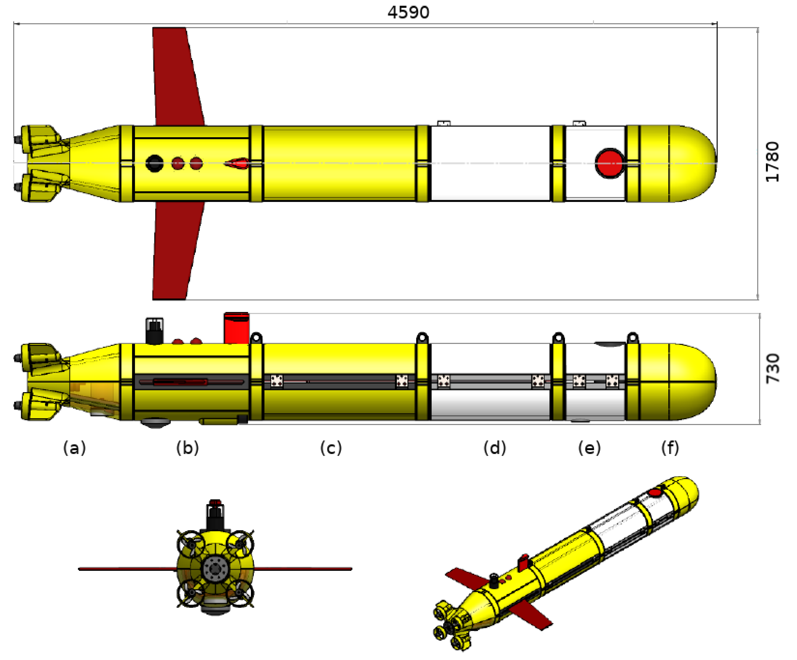
3.1. Hybrid Underwater Autonomous Vehicle
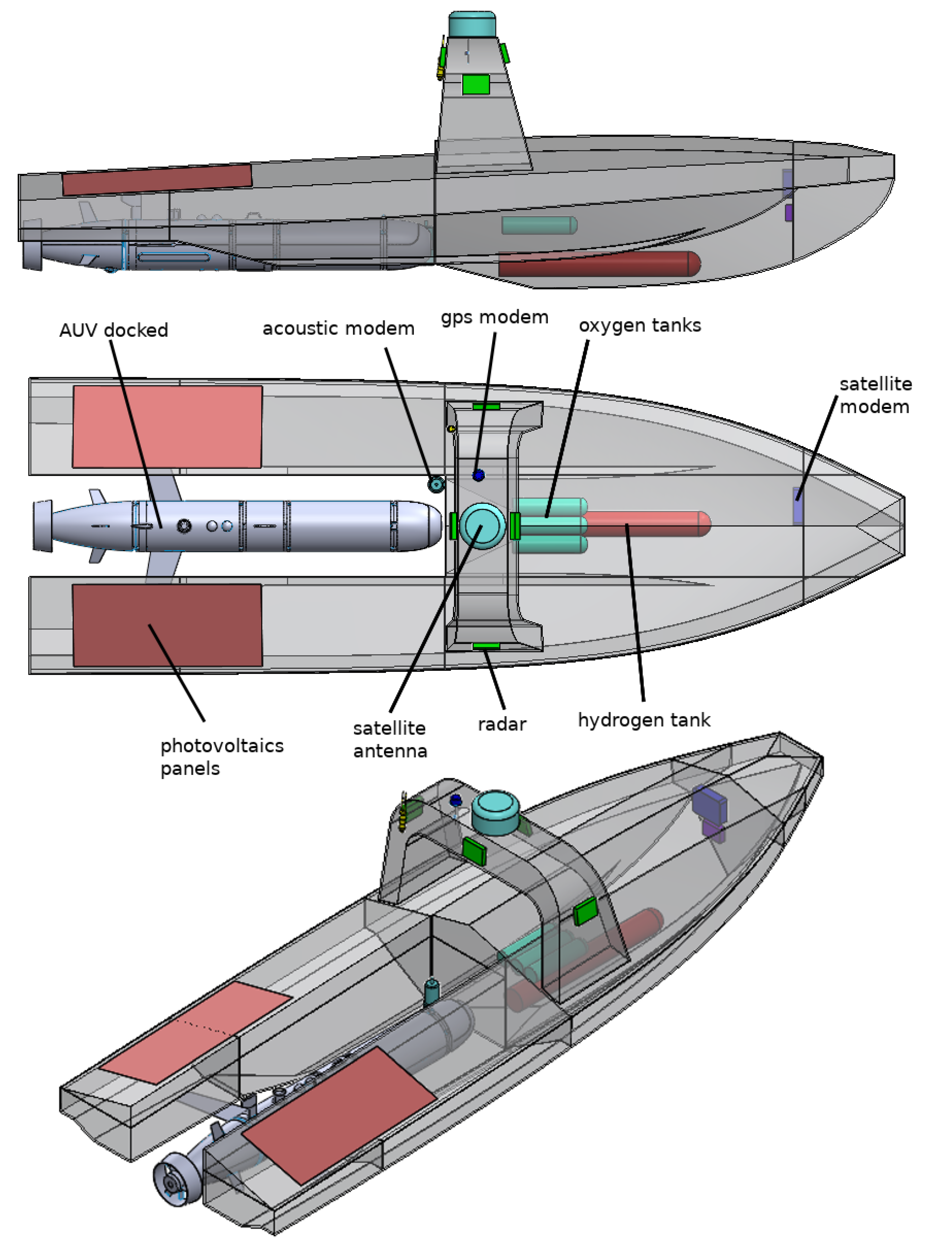
3.2. Unmanned Surface Vehicle
3.3. Power Pack and Energy Management
3.4. Mission Planning
3.5. Data Sensing, Storage and Processing
3.6. SeaCube: A Third Party Payload
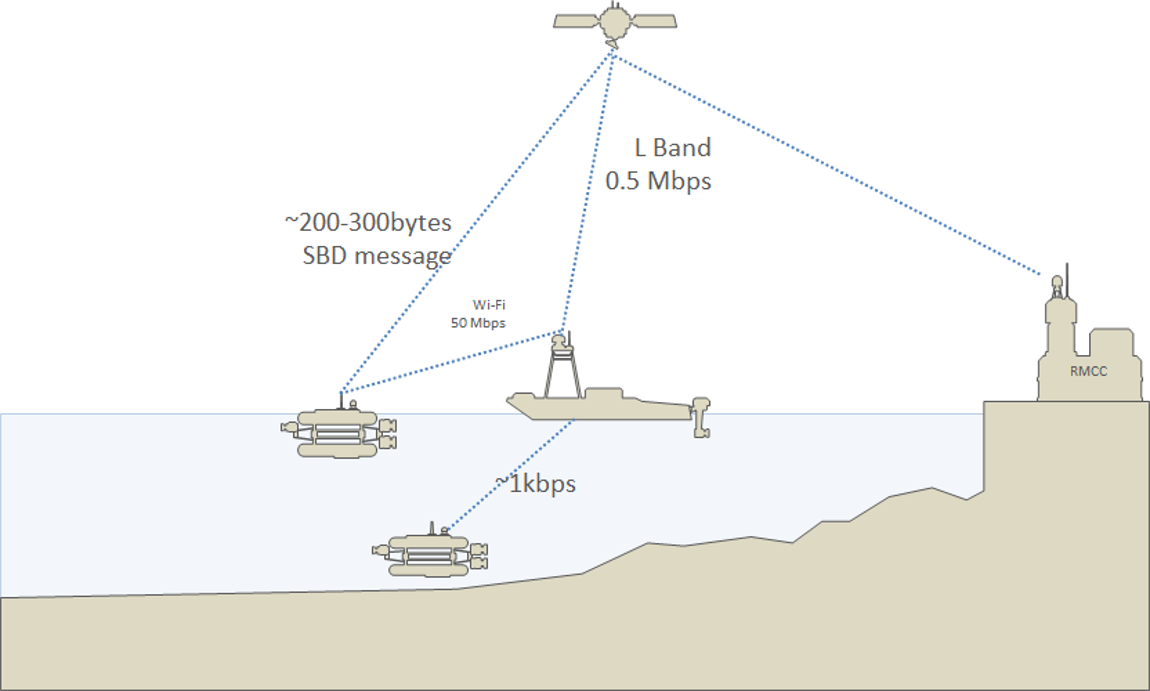
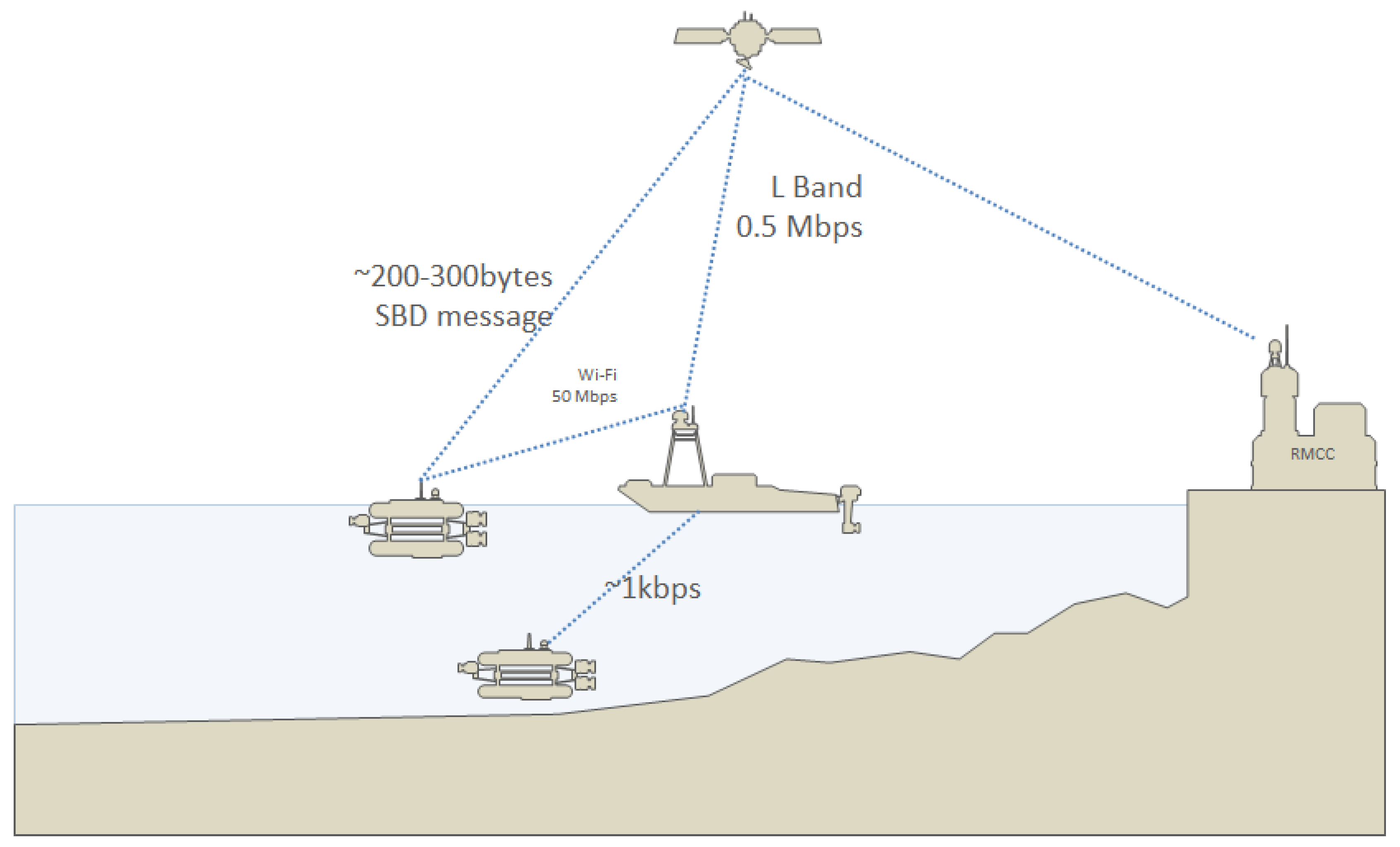
3.7. Data Communication
4. Discussion
5. Conclusions
Author Contributions
Funding
Acknowledgments
Conflicts of Interest
References
- Rahmstorf, S. Ocean circulation and climate during the past 120,000 years. Nature 2002, 419, 207–214. [Google Scholar] [CrossRef] [PubMed]
- Mora, C.; Tittensor, D.P.; Adl, S.; Simpson, A.G.B.; Worm, B. How Many Species Are There on Earth and in the Ocean? PLoS Biol. 2011, 9, 1–8. [Google Scholar] [CrossRef] [PubMed]
- Danovaro, R.; Aguzzi, J.; Fanelli, E.; Billett, D.; Gjerde, K.; Jamieson, A.; Ramirez-Llodra, E.; Smith, C.R.; Snelgrove, P.V.R.; Thomsen, L.; et al. An ecosystem-based deep-ocean strategy. Science 2017, 355, 452–454. [Google Scholar] [CrossRef] [PubMed]
- Grizzetti, B.; Lanzanova, D.; Liquete, C.; Reynaud, A.; Cardoso, A. Assessing water ecosystem services for water resource management. Environ. Sci. Policy 2016, 61, 194–203. [Google Scholar] [CrossRef]
- Sokolov, S.; Zhilenkov, A.; Nyrkov, A.; Chernyi, S. The Use Robotics for Underwater Research Complex Objects. In Computational Intelligence in Data Mining; Behera, H.S., Mohapatra, D.P., Eds.; Springer: Singapore, 2017; pp. 421–427. [Google Scholar]
- Eddy Lee, Y.D.; George, R.A. High-resolution geological AUV survey results across a portion of the eastern Sigsbee Escarpment. AAPG Bull. 2004, 88, 747–764. [Google Scholar] [CrossRef]
- Bickle, M.; Chadwick, A.; Huppert, H.E.; Hallworth, M.; Lyle, S. Modelling carbon dioxide accumulation at Sleipner: Implications for underground carbon storage. Earth Planet. Sci. Lett. 2007, 255, 164–176. [Google Scholar] [CrossRef]
- Draycott, S.; Sellar, B.; Davey, T.; Noble, D.; Venugopal, V.; Ingram, D. Capture and simulation of the ocean environment for offshore renewable energy. Renew. Sustain. Energy Rev. 2019, 104, 15–29. [Google Scholar] [CrossRef]
- Aguzzi, J.; Chatzievangelou, D.; Marini, S.; Fanelli, E.; Danovaro, R.; Flögel, S.; Lebris, N.; Juanes, F.; De Leo, F.C.; Del Rio, J.; et al. New High-Tech Flexible Networks for the Monitoring of Deep-Sea Ecosystems. Environ. Sci. Technol. 2019, 53, 6616–6631. [Google Scholar] [CrossRef]
- Aguzzi, J.; Chatzievangelou, D.; Francescangeli, M.; Marini, S.; Bonofiglio, F.; del Rio, J.; Danovaro, R. The Hierarchic Treatment of Marine Ecological Information from Spatial Networks of Benthic Platforms. Sensors 2020, 20, 1751. [Google Scholar] [CrossRef]
- GEBCO. General Bathymetric Chart of Oceans. 2020. Available online: https://www.gebco.net/ (accessed on 8 March 2020).
- IHO. International Hydrographic Organization. 2020. Available online: https://iho.int/ (accessed on 8 March 2020).
- IOC. Intergovernmental Oceanographic Commission. 2020. Available online: http://www.ioc-unesco.org/ (accessed on 8 March 2020).
- Wynn, R.B.; Huvenne, V.A.; Bas, T.P.L.; Murton, B.J.; Connelly, D.P.; Bett, B.J.; Ruhl, H.A.; Morris, K.J.; Peakall, J.; Parsons, D.R.; et al. Autonomous Underwater Vehicles (AUVs): Their past, present and future contributions to the advancement of marine geoscience. Mar. Geol. 2014, 352, 451–468. [Google Scholar] [CrossRef]
- Nilssen, I.; Ødegård, Ø.; Sørensen, A.J.; Johnsen, G.; Moline, M.A.; Berge, J. Integrated environmental mapping and monitoring, a methodological approach to optimise knowledge gathering and sampling strategy. Mar. Pollut. Bull. 2015, 96, 374–383. [Google Scholar] [CrossRef] [PubMed]
- Ludvigsen, M.; Sørensen, A.J. Towards integrated autonomous underwater operations for ocean mapping and monitoring. Annu. Rev. Control 2016, 42, 145–157. [Google Scholar] [CrossRef]
- Verfuss, U.K.; Aniceto, A.S.; Harris, D.V.; Gillespie, D.; Fielding, S.; Jiménez, G.; Johnston, P.; Sinclair, R.R.; Sivertsen, A.; Solbø, S.A.; et al. A review of unmanned vehicles for the detection and monitoring of marine fauna. Mar. Pollut. Bull. 2019, 140, 17–29. [Google Scholar] [CrossRef] [PubMed]
- Scherwath, M.; Thomsen, L.; Riedel, M.; Römer, M.; Chatzievangelou, D.; Schwendner, J.; Duda, A.; Heesemann, M. Ocean Observatories as a Tool to Advance Gas Hydrate Research. Earth Space Sci. 2019, 6, 2644–2652. [Google Scholar] [CrossRef]
- Aguzzi, J.; Albiez, J.; Flögel, S.; Godø, O.R.; Grimsbø, E.; Marini, S.; Pfannkuche, O.; Rodriguez, E.; Thomsen, L.; Torkelsen, T.; et al. A Flexible Autonomous Robotic Observatory Infrastructure for Bentho-Pelagic Monitoring. Sensors 2020, 20, 1614. [Google Scholar] [CrossRef] [PubMed]
- Brito, M.; Smeed, D.; Griffiths, G. Underwater Glider Reliability and Implications for Survey Design. J. Atmos. Ocean. Technol. 2014, 31, 2858–2870. [Google Scholar] [CrossRef]
- Sánchez, P.J.B.; Papaelias, M.; Márquez, F.P.G. Autonomous underwater vehicles: Instrumentation and measurements. IEEE Instrum. Meas. Mag. 2020, 23, 105–114. [Google Scholar] [CrossRef]
- Micallef, A.; Krastel, S.; Savini, A. Submarine Deomorphology; Springer: Berlin/Heidelberg, Germany, 2018. [Google Scholar]
- Pergent, G.; Monnier, B.; Clabaut, P.; Gascon, G.; Pergent-Martini, C.; Valette-Sansevin, A. Innovative method for optimizing Side-Scan Sonar mapping: The blind band unveiled. Estuar. Coast. Shelf Sci. 2017, 194, 77–83. [Google Scholar] [CrossRef]
- Wang, V.T.; Hayes, M.P. Synthetic Aperture Sonar Track Registration Using SIFT Image Correspondences. IEEE J. Ocean. Eng. 2017, 42, 901–913. [Google Scholar] [CrossRef]
- Mizuno, K.; Saito, Y.; Katase, F.; Nagahashi, K.; Asada, A. Development of the parametric sub-bottom profiler for autonomous underwater vehicles—Prediction of the reflection level using sonar equation based on TBE and Biot-Stoll model. In Proceedings of the 2017 IEEE Underwater Technology (UT), Busan, Korea, 21–24 February 2017; pp. 1–4. [Google Scholar] [CrossRef]
- Matsuda, T.; Maki, T.; Sakamaki, T. Accurate and Efficient Seafloor Observations With Multiple Autonomous Underwater Vehicles: Theory and Experiments in a Hydrothermal Vent Field. IEEE Robot. Autom. Lett. 2019, 4, 2333–2339. [Google Scholar] [CrossRef]
- Johnsen, G.; Ludvigsen, M.; Sørensen, A.; Aas, L.M.S. The use of underwater hyperspectral imaging deployed on remotely operated vehicles-methods and applications. IFAC-PapersOnLine 2016, 49, 476–481. [Google Scholar] [CrossRef]
- Yu, Y.; Bian, Q.; Lu, Y.; Zhang, X.; Yang, J.; Liang, L. High Sensitivity All Optical Fiber Conductivity-Temperature-Depth (CTD) Sensing Based on an Optical Microfiber Coupler (OMC). J. Light. Technol. 2019, 37, 2739–2747. [Google Scholar] [CrossRef]
- Yu, C.; Xiang, X.; Lapierre, L.; Zhang, Q. Robust Magnetic Tracking of Subsea Cable by AUV in the Presence of Sensor Noise and Ocean Currents. IEEE J. Ocean. Eng. 2018, 43, 311–322. [Google Scholar] [CrossRef]
- Meurer, C.; Fuentes-Perez, J.F.; Schwarzwalder, K.; Ludvigsen, M.; Sorensen, A.J.; Kruusmaa, M. 2D Estimation of Velocity Relative to Water and Tidal Currents based on Differential Pressure for Autonomous Underwater Vehicles. IEEE Robot. Autom. Lett. 2020. [Google Scholar] [CrossRef]
- Thomson, D.J.M.; Dosso, S.E.; Barclay, D.R. Modeling AUV Localization Error in a Long Baseline Acoustic Positioning System. IEEE J. Ocean. Eng. 2018, 43, 955–968. [Google Scholar] [CrossRef]
- Taudien, J.Y.; Bilén, S.G. Quantifying Long-Term Accuracy of Sonar Doppler Velocity Logs. IEEE J. Ocean. Eng. 2018, 43, 764–776. [Google Scholar] [CrossRef]
- Meurer, C.; Francisco Fuentes-Pérez, J.; Palomeras, N.; Carreras, M.; Kruusmaa, M. Differential Pressure Sensor Speedometer for Autonomous Underwater Vehicle Velocity Estimation. IEEE J. Ocean. Eng. 2019, 1–33. [Google Scholar] [CrossRef]
- Kok, M.; Hol, J.D.; Schön, T.B. Using Inertial Sensors for Position and Orientation Estimation. arXiv 2017, arXiv:1704.06053. [Google Scholar]
- Eichhorn, M.; Ament, C.; Jacobi, M.; Pfuetzenreuter, T.; Karimanzira, D.; Bley, K.; Boer, M.; Wehde, H. Modular AUV System with Integrated Real-Time Water Quality Analysis. Sensors 2018, 18, 1837. [Google Scholar] [CrossRef]
- Armstrong, R.; Pizarro, O.; Roman, C. Underwater Robotic Technology for Imaging Mesophotic Coral Ecosystems. In Mesophotic Coral Ecosystems; Loya, Y., Puglise, K., Bridge, T., Eds.; Springer: Cham, Switzerland, 2019; Chapter 12. [Google Scholar]
- Lynch, B.; Ellery, A. Efficient Control of an AUV-Manipulator System: An Application for the Exploration of Europa. IEEE J. Ocean. Eng. 2014, 39, 552–570. [Google Scholar] [CrossRef]
- Jawhar, I.; Mohamed, N.; Al-Jaroodi, J.; Zhang, S. An Architecture for Using Autonomous Underwater Vehicles in Wireless Sensor Networks for Underwater Pipeline Monitoring. IEEE Trans. Ind. Informatics 2019, 15, 1329–1340. [Google Scholar] [CrossRef]
- Couillard, M.; Fawcett, J.; Davison, M. Optimizing Constrained Search Patterns for Remote Mine-Hunting Vehicles. IEEE J. Ocean. Eng. 2012, 37, 75–84. [Google Scholar] [CrossRef]
- Stilinovic, N.; Nad, D.; Miskovic, N. AUV for diver assistance and safety—Design and implementation. In Proceedings of the OCEANS 2015-Genova, Genoa, Italy, 18–21 May 2015; pp. 1–4. [Google Scholar] [CrossRef]
- Ødegård, Ø.; Sørensen, A.J.; Hansen, R.E.; Ludvigsen, M. A new method for underwater archaeological surveying using sensors and unmanned platforms. IFAC-PapersOnLine 2016, 49, 486–493. [Google Scholar] [CrossRef]
- Kukulya, A.L.; Stokey, R.; Fiester, C.; Padilla, E.M.H.; Skomal, G. Multi-vehicle autonomous tracking and filming of white sharks Carcharodon carcharias. In Proceedings of the 2016 IEEE/OES Autonomous Underwater Vehicles (AUV), Tokyo, Japan, 6–9 November 2016; pp. 423–430. [Google Scholar] [CrossRef]
- Zadeh, S.M.; Powers, D.M.; Sammut, K. An autonomous reactive architecture for efficient AUV mission time management in realistic dynamic ocean environment. Robot. Auton. Syst. 2017, 87, 81–103. [Google Scholar] [CrossRef]
- E.U. ENDURUNS: Development and demonstration of a long-endurance sea surveying autonomous unmanned vehicle with gliding capability powered by hydrogen fuel cell. H2020-EU.3.4.-SOCIETAL CHALLENGES-Smart, Green And Integrated Transport, MG-BG-01-2018-Unmanned and autonomous survey activities at sea, Overall budget:Eur 8.747.7656. 2018–2022. 2018. Available online: https://enduruns.eu/ (accessed on 8 March 2020).
- Caffaz, A.; Caiti, A.; Casalino, G.; Turetta, A. The Hybrid Glider/AUV Folaga. IEEE Robot. Autom. Mag. 2010, 17, 31–44. [Google Scholar] [CrossRef]
- Woithe, H.C.; Kremer, U. Feature based adaptive energy management of sensors on autonomous underwater vehicles. Ocean Eng. 2015, 97, 21–29. [Google Scholar] [CrossRef]
- Segovia, I.; Pliego, A.; Papaelias, M.; García Márquez, F. Optimal management of marine inspection with autonomous underwater vehicles. Adv. Intell. Syst. Comput. 2020, 1001, 760–771. [Google Scholar]
- Gjeci, N.; Govindaraj, S.; Coene, S.; But, A.; Ottaviani, E. Transmission of classified and varying quality underwater maps over constrained networks. In Proceedings of the IMEKO TC-19 International Workshop on Metrology for the Sea, Genova, Italy, 3–5 October 2019. [Google Scholar]
- Zolich, A.; Palma, D.; Kansanen, K.; Fjørtoft, K.; Sousa, J.; Johansson, K.H.; Jiang, Y.; Dong, H.; Johansen, T.A. Survey on Communication and Networks for Autonomous Marine Systems. J. Intell. Robot. Syst. 2019, 95, 789–813. [Google Scholar] [CrossRef]
- Vasilijevic, A.; Nad, D.; Mandic, F.; Miskovic, N.; Vukic, Z. Coordinated Navigation of Surface and Underwater Marine Robotic Vehicles for Ocean Sampling and Environmental Monitoring. IEEE/ASME Trans. Mechatronics 2017, 22, 1174–1184. [Google Scholar] [CrossRef]
- Sarda, E.I.; Dhanak, M.R. Launch and Recovery of an Autonomous Underwater Vehicle From a Station-Keeping Unmanned Surface Vehicle. IEEE J. Ocean. Eng. 2019, 44, 290–299. [Google Scholar] [CrossRef]
- Roper, D.T.; Phillips, A.B.; Harris, C.A.; Salavasidis, G.; Pebody, M.; Templeton, R.; Amma, S.V.S.; Smart, M.; McPhail, S. Autosub long range 1500: An ultra-endurance AUV with 6000 Km range. In Proceedings of the OCEANS 2017-Aberdeen, Aberdeen, UK, 19–22 June 2017; pp. 1–5. [Google Scholar]
- McPhail, S.; Templeton, R.; Pebody, M.; Roper, D.; Morrison, R. Autosub Long Range AUV Missions Under the Filchner and Ronne Ice Shelves in the Weddell Sea, Antarctica-an Engineering Perspective. In Proceedings of the OCEANS 2019-Marseille, Marseille, France, 17–20 June 2019; pp. 1–8. [Google Scholar] [CrossRef]
- Yan, G.X.; Pan, G.; Shi, Y.; Chao, L.M.; Zhang, D. Experimental and numerical investigation of water impact on air-launched AUVs. Ocean Eng. 2018, 167, 156–168. [Google Scholar] [CrossRef]
- Pan, C.J.; Guo, Y.Q. Design and Simulation of High Altitude Air-Launched Automatic Underwater Vehicles. Appl. Mech. Mater. 2012, 128, 1386–1391. [Google Scholar] [CrossRef]
- Stevenson, P. Report on Air Launched Autonomous Underwater Vehicles; (National Oceanography Centre Research and Consultancy Report, 4); National Oceanography Centre: Southampton, UK, 2011; 80p, Available online: https://eprints.soton.ac.uk/188105/ (accessed on 27 July 2020).
- Fan, S.; Li, B.; Xu, W.; Xu, Y. Impact of Current Disturbances on AUV Docking: Model-Based Motion Prediction and Countering Approaches. IEEE J. Ocean. Eng. 2018, 43, 888–904. [Google Scholar] [CrossRef]
- Gonzalez, C.E.; Rojas, C.J.; Bergel, A.; Diaz, M.A. An Architecture-Tracking Approach to Evaluate a Modular and Extensible Flight Software for CubeSat Nanosatellites. IEEE Access 2019, 7, 126409–126429. [Google Scholar] [CrossRef]
- Fezzani, R.; Berger, L. Analysis of calibrated seafloor backscatter for habitat classification methodology and case study of 158 spots in the Bay of Biscay and Celtic Sea. Mar. Geophys. Res. 2018, 39, 169–181. [Google Scholar] [CrossRef]
- Gavazzi, G.M.; Madricardo, F.; Janowski, L.; Kruss, A.; Blondel, P.; Sigovini, M.; Foglini, F. Evaluation of seabed mapping methods for fine-scale classification of extremely shallow benthic habitats—Application to the Venice Lagoon, Italy. Estuar. Coast. Shelf Sci. 2016, 170, 45–60. [Google Scholar] [CrossRef]
- Madricardo, F.; Foglini, F.; Campiani, E.; Grande, V.; Catenacci, E.; Petrizzo, A.; Kruss, A.; Toso, C.; Trincardi, F. Assessing the human footprint on the sea-floor of coastal systems: The case of the Venice Lagoon, Italy. Sci. Rep. 2019, 9, 6615. [Google Scholar] [CrossRef]
- Liu, Q.; Yan, Z.; Wang, E.; Wang, S.; Sun, G. A high-specific-energy magnesium/water battery for full-depth ocean application. Int. J. Hydrogen Energy 2017, 42, 23045–23053. [Google Scholar] [CrossRef]
- Mori, R. Electrochemical properties of a rechargeable aluminum–air battery with a metal–organic framework as air cathode material. RSC Adv. 2017, 7, 6389–6395. [Google Scholar] [CrossRef]
- Weydahl, H.; Gilljam, M.; Lian, T.; Johannessen, T.C.; Holm, S.I.; Øistein Hasvold, J. Fuel cell systems for long-endurance autonomous underwater vehicles—Challenges and benefits. Int. J. Hydrogen Energy 2020, 45, 5543–5553. [Google Scholar] [CrossRef]
- Zou, Z.; Xu, J.; Mi, C.; Cao, B.; Chen, Z. Evaluation of Model Based State of Charge Estimation Methods for Lithium-Ion Batteries. Energies 2014, 7, 5065–5082. [Google Scholar] [CrossRef]
- Chin, C.S.; Jia, J.; Chiew, J.H.K.; Toh, W.D.; Gao, Z.; Zhang, C.; McCann, J. System design of underwater battery power system for marine and offshore industry. J. Energy Storage 2019, 21, 724–740. [Google Scholar] [CrossRef]
- Makhsoos, A.; Mousazadeh, H.; Mohtasebi, S.S.; Abdollahzadeh, M.; Jafarbiglu, H.; Omrani, E.; Salmani, Y.; Kiapey, A. Design, simulation and experimental evaluation of energy system for an unmanned surface vehicle. Energy 2018, 148, 362–372. [Google Scholar] [CrossRef]
- Li, Z.; Huang, J.; Liaw, B.Y.; Zhang, J. On state-of-charge determination for lithium-ion batteries. J. Power Sources 2017, 348, 281–301. [Google Scholar] [CrossRef]
- Norbit. Wideband Multibeam Sonar. 2020. Available online: https://norbit.com/media/PS-120005-22_WBMS-bathy_Pn_12003-AACDB4_A4.pdf (accessed on 27 March 2020).
- Marini, S.; Griffa, A.; Aliani, S.; Conversi, A.; Shroeder, K.; Borghini, M. EP2863257 (A1)-Underwater images acquisition and processing system. Available online: https://data.epo.org/gpi/EP2863257A1 (accessed on 8 March 2020).
- Corgnati, L.; Marini, S.; Mazzei, L.; Ottaviani, E.; Aliani, S.; Conversi, A.; Griffa, A. Looking inside the Ocean: Toward an Autonomous Imaging System for Monitoring Gelatinous Zooplankton. Sensors 2016, 16, 2124. [Google Scholar] [CrossRef]
- Marini, S.; Corgnati, L.; Mantovani, C.; Bastianini, M.; Ottaviani, E.; Fanelli, E.; Aguzzi, J.; Griffa, A.; Poulain, P.M. Automated estimate of fish abundance through the autonomous imaging device GUARD1. Measurement 2018, 126, 72–75. [Google Scholar] [CrossRef]
- Monteiro, A.; de Oliveira, M.; de Oliveira, R.; da Silva, T. Embedded application of convolutional neural networks on Raspberry Pi for SHM. Electron. Lett. 2018, 54, 680–682. [Google Scholar] [CrossRef]
- Portell, J.; Amblas, D.; Mitchell, G.; Morales, M.; Villafranca, A.G.; Iudica, R.; Lastras, G. High-Performance Compression of Multibeam Echosounders Water Column Data. IEEE J. Sel. Top. Appl. Earth Obs. Remote Sens. 2019, 12, 1771–1783. [Google Scholar] [CrossRef]
- Hussain, T.; Muhammad, K.; Ser, J.D.; Baik, S.W.; de Albuquerque, V.H.C. Intelligent Embedded Vision for Summarization of Multiview Videos in IIoT. IEEE Trans. Ind. Inform. 2020, 16, 2592–2602. [Google Scholar] [CrossRef]
- Raspberry. Raspberry Pi 4 Model B. 2019. Available online: https://www.raspberrypi.org/products/raspberry-pi-4-model-b/ (accessed on 27 March 2020).
- Campos, R.; Quintana, J.; Garcia, R.; Schmitt, T.; Spoelstra, G.; M. A. Schaap, D. 3D Simplification Methods and Large Scale Terrain Tiling. Remote Sens. 2020, 12, 437. [Google Scholar] [CrossRef]
- Marini, S.; Fanelli, E.; Sbragaglia, V.; Azzurro, E.; Del Rio Fernandez, J.; Aguzzi, J. Tracking Fish Abundance by Underwater Image Recognition. Sci. Rep. 2018, 8, 13748. [Google Scholar] [CrossRef] [PubMed]
- Lopez-Vazquez, V.; Lopez-Guede, J.M.; Marini, S.; Fanelli, E.; Johnsen, E.; Aguzzi, J. Video Image Enhancement and Machine Learning Pipeline for Underwater Animal Detection and Classification at Cabled Observatories. Sensors 2020, 20, 726. [Google Scholar] [CrossRef] [PubMed]
- NVIDIA. NVIDIA Jetson Technical Specifications. 2019. Available online: https://developer.nvidia.com/embedded/develop/hardware (accessed on 27 March 2020).
- OpenCV. Open Computer Vision. 2020. Available online: https://opencv.org/ (accessed on 14 July 2020).
- Lecun, Y.; Bengio, Y.; Hinton, G. Deep learning. Nature 2015, 521, 436–444. [Google Scholar] [CrossRef] [PubMed]
- Samson, J.R.; Malphrus, B.K. Update on Dependable Multiprocessor (DM) CubeSat technology development: ISS (International Space Station) flight experiments. In Proceedings of the 2015 IEEE Aerospace Conference, Big Sky, MT, USA, 7–14 March 2015; pp. 1–11. [Google Scholar]
- Wuerl, A.; Wuerl, M. Lessons learned for deploying a microsatellite from the International Space Station. In Proceedings of the 2015 IEEE Aerospace Conference, Big Sky, MT, USA, 7–14 March 2015; pp. 1–12. [Google Scholar]
- Naik, H.; Awasthi, A.K.; Harish, A.R. Shared-aperture dual-band orthogonally polarised antenna array for L-band and S-band applications. IET Microwaves Antennas Propag. 2019, 13, 431–435. [Google Scholar] [CrossRef]
- ICES. Report of the Second Workshop on Practical Implementation of Statistical Sound Catch Sampling Programmes. In Proceedings of the ICES CM 2012/ACOM:52, Copenhagen, Denmark, 6–9 November 2012; 71pAvailable online: https://www.ices.dk/sites/pub/PublicationReports/ExpertGroupReport/acom/2012/WKPICS2/WKPICS2finalreportfebupdate.pdf (accessed on 27 July 2020).
- Angeletti, L.; Taviani, M.; Canese, S.; Foglini, F.; Mastronotaro, F.; Argnani, A.; Trincardi, F.; Barkan-Petriciolo, T.; Ceregato, A.; Chimenti, G.; et al. New deep-water cnidarian sites in the southern Adriatic Sea. Mediterr. Mar. Sci. 2013, 15, 263–273. [Google Scholar] [CrossRef]
- Vladas, Z.; Algirdas, G. Drowned Early Mesolithic Landscapes on the Baltic Sea Bed in the Lithuanian Waters. J. Environ. Sci. Eng. 2014, 274–289. [Google Scholar] [CrossRef]


| Sensor Type | Use & Description | Reference |
|---|---|---|
| Active sonar: This class of instruments are used to measure reflected acoustic signals documenting the objects on the seabed or in the water column. | Multibeam echo-sounders (MBES): acoustic beams with known directions are used to estimates the backscattering of the particulate suspended in the water column and/or the back scattering of the seabed. These sensors produce a 2.5D model bathymetry and the terrain characterization. | [22] |
| Side scan sonars (SSS): this sensor measures the acoustic surface reflectance of the seabed producing a map of the seabed’s acoustical reflectivity. | [23] | |
| Synthetic aperture sonar (SAS): these systems use several pings’ simultaneously for each seabed point establishing a virtual transducer array providing better range and increased seabed resolution compared to conventional SSS. | [24] | |
| Sub bottom profilers (SBP): produce information about the sub-seabed structures. The system transmits low frequency, high power acoustical pulses that are able to penetrate the seabed. Measuring the intensity of the reflected signal, the sub seafloor conditions are recorded. | [25] | |
| Imaging: sensors that provide subsea information in different picture formats. | Video camera: High resolution qualitative information about shape, colour and texture of the seabed and of the objects lying on it. The processes measured by optical imaging can be e.g., geological, archaeological and ecological. | [26] |
| Hyperspectral Imaging: High resolution qualitative information about the absorption of different wavelengths of the seabed minerals and organisms and of several substances dissolved in the water column (e.g., chlorophyll, pigments) | [27] | |
| Conductivity Temperature Depth (CTD) | This sensors measure conductivity, temperature and pressure of the sea water. Salinity, speed of sound and seawater density are calculated from these fundamental parameters. | [28] |
| Magnetometer | This sensor can be used for localizing man-made objects like shipwrecks in archaeology. They are also used to measure the magnetic characteristics of seabed rocks. | [29] |
| Acoustic Doppler Current Profiler (ADCP) | The instrument measures the backscatter intensity and Doppler shift of an acoustic reflection signal and it is used to measure the velocity of the currents. It provides a profile of three-dimensional current vectors. | [30] |
| Navigation sensors: This calss of instruments is used as positioning sensors for underwater operations | Acoustic baseline sensors: they measure the phase of the incoming signal to determine direction. The result is a position derived from range and phase angle. | [31] |
| Doppler Velocity Log (DVL): They measure the Doppler shift in the incoming signal reflected off the seabed (bottom track mode) or particles in the water (water track mode) column using the same principles as ADCP. Having several transducers pointing in different directions, velocity of all three axis is observable. | [32] | |
| Pressure sensors: Together with the estimate of gravity, these class of sensors are used to estimate the accurate depth or the speed of a vehicle. | [33] | |
| Inertial sensors: Integrating the acceleration and rate of changes of the orientation angles in the time domain provide state estimates for position, orientation angles velocities and accelerations. Inertial navigation systems use auxiliary sensors such as DVL, pressure sensors, acoustics or even GPS to augment the measurements. | [34] |
| Application | Description | References |
|---|---|---|
| Research | Seabed Morphology: High-resolution bathymetric and magnetic field maps of the seafloor for discovering and monitoring: scarps, active deformation and seismicity, submarine canyons and channels, fine-scale relief. | [22] |
| Water quality: Mapping and monitoring of deep-water hydrothermal processes and water conditions. | [35] | |
| Marine Life: MBES, photographic and SSS surveys for coral reef, megabenthos and demersal fish monitoring. | [36] | |
| Biogeology Sampling: Bed rock, boulder, coarse (mixed sediment), mega-ripples and fine rippled (sands and muddy sands) | [37] | |
| Industry | Oil and Gas: Pipelines and conductions monitoring, Underwater works as welding or maintenance management. | [38] |
| Electrical Lines: Monitorization and repairs of cable lines in subsea environment | [29] | |
| Military: Inspections and surveys developed for army targets. Mapping of undiscover areas of interest for political or strategical motivation. | [39] | |
| Leisure | Sports Events: Using navigation methods for sea sports or marine challenges | [40] |
| Wrecks Inspections: Using sonar and positioning technologies for ships or planes falling down detection and wrecks recovery operations. | [41] | |
| Films: Cinema tool, specific cameras used to record marine environments for documental or films | [42] |
| State of the Art AUV | ENDURUNS Hybrid System | Measure of Improvement |
|---|---|---|
| Reduced operational endurance due to limitations in state of the art battery technology (0.15–0.25 kWh/kg for commercially available Li-ion batteries) | Operational endurance increased to the use of high-energy density and fuel cells (33 kWh/kg) | The amount of energy stored onboard can be potentially increased to almost 1800% when 6 kg of are used |
| Support surface vessel required for deployment, recovery and operations | USV used for geotagging, data transfer and transmission of commands from the RMCC | No special support surface vessel required by using an autonomous USV instead |
| Navigation based on the use of underwater beacons or data transmitted from a supporting surface vessel | Navigation based on geotagging data transmitted from USV or form instructions transmitted form the RMCC | High-resolution geotagging enabling compatible data output as required by the “Seabed 2030” initiative |
| Gliding operations restricted to sinusoidal trajectories limiting usefulness and versatility | Gliding operations combined with horizontal trajectories | Hybrid operation taking advantage by glider navigation and thrusters in AUV mode |
| Basic control systems | Advanced control system for determining power requirements and adjusting power consumption dynamically | Dynamic power consumption based on input received from sensors onboard measuring speed and data analysis |
| Basic communication capabilities mainly based on the use of a supporting surface vessel | Reliable quasi-real-time communication capability for bidirectional data transfer | Secure dynamic communication with RMCC combined with onboard data analysis and compression |
| Several hours needed for recharging the battery banks is required unless old ones are removed and replaced | refuelling can be achieved in a few minutes time | Various storage options available which can be adapted according to each mission’s specific requirements |
| Component | Model | Description |
|---|---|---|
| Thrusters | Model 550 AUV, Tecnadyne | propeller specifically developed for submarine vehicles. The forward force at 3 knots is about 12 kgf |
| Doppler Velocity Log (DVL) | 500, Nortek | it provides the AUV altitude from the bottom between 0.3 m and 200 m |
| Inertial Navigation System (INS) | Phins C3, iXBlue, | based on FOG (Fiber Optic Gyro) technology it provides very accurate angular measurements and position estimations |
| Acoustic Modem and USBL transponder | S2CR 18/34H, EvoLogics | AUV/USV underwater acoustic communication with additional functionality of acoustic transponder |
| Depthmeter | PA-33x, Keller | nominal accuracy of 0.02% of its maximum value |
| Attitude and Heading Reference System (AHRS) | Orientus, Advanced | it measures the heading and attitude of the vehicle only while gliding |
| GPS receiver | NEO-6M-0-001, Ublox | it computes the absolute AUV position at sea surface |
| Inductive charger | Maelstrom, WiSub | allows data transfer and power when the AUV and USV are docked. |
| Component | Model | Description |
|---|---|---|
| Thrusters Engines | BlueRobotics T200 | the USV is equipped with two thrusters, 390 W each |
| Autopilot Unit | SPECTRE AP PCB | remote control autopilot for USV |
| Radar | UMRR Type 42 | 3D object tracking in ultra high definition for traffic radar |
| GPS Receiver | UBLOX NEO-M8N (USB Dongle) | it compute the absolute USV position |
| GPS Antenna | AQHA.50.A.301111 | active multi-band Global Navigation Satellite System (GNSS) |
| CPU Power source | Neousys Rugged Intel 6th Gen Computer | compact fanless rugged embedded computer |
| Satellite Modem & antenna | Thales VesseLINK | global satellite coverage for maritime communications, with uninterrupted coverage from pole to pole |
| Wi-Fi modem & antenna | WL-WN570HN2 | Long-Range high performance links |
| Acoustic system USBL | EVOLOGICS USBL | AUV/USV underwater acoustic communication with additional functionality of acoustic transponder |
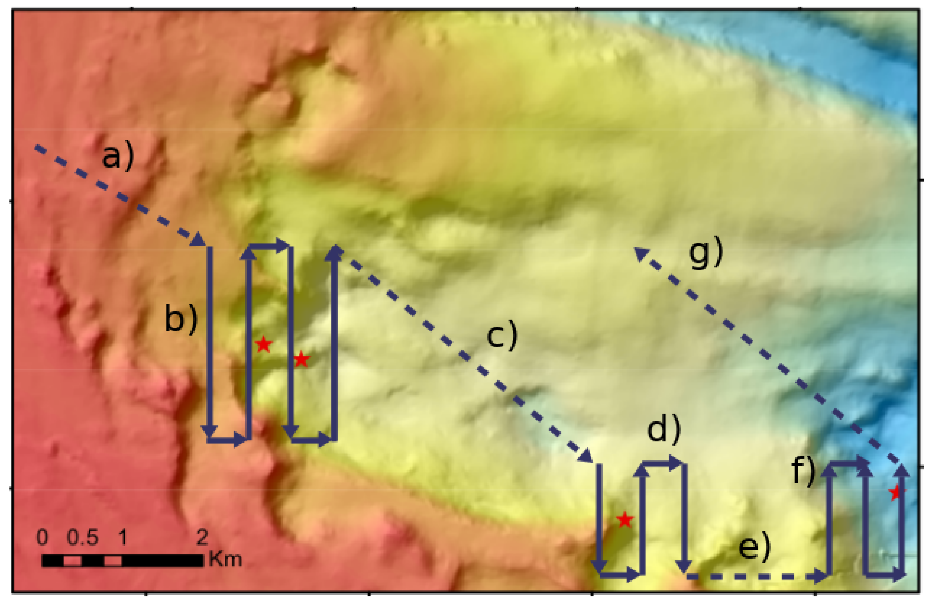
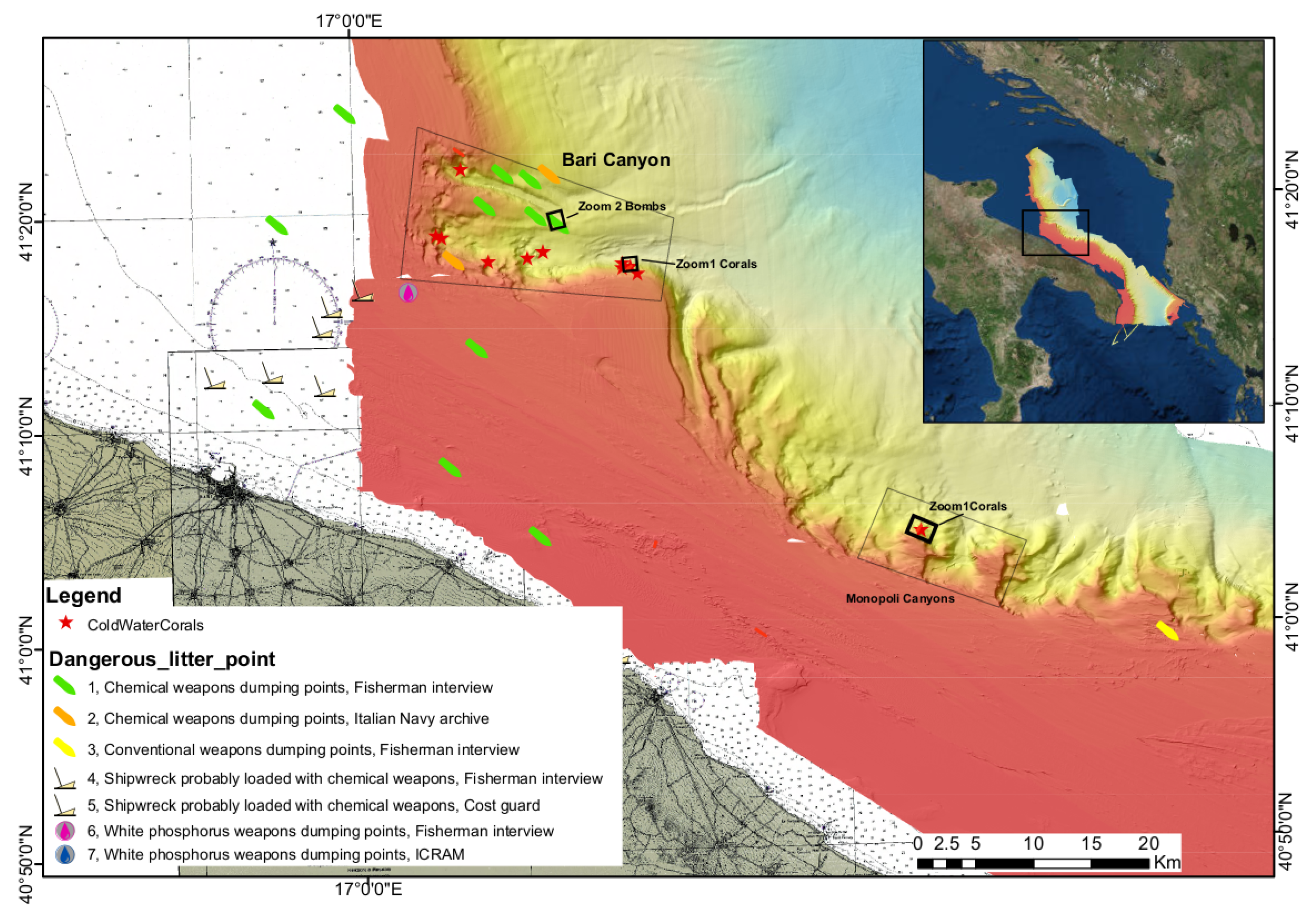
| Parameters | Large Area | Zoom 1 | Zoom 2 |
|---|---|---|---|
| Min Depth (m) | 130 | 315 | 506 |
| Max Depth (m) | 850 | 782 | 613 |
| Distance form the Seafloor (m) | 200 | 50 | 50 |
| MBES Swath Width (km) | 0.8 | 0.2 | 0.2 |
| MBES Footprint (m) | 3.5 | 0.9 | 0.9 |
| Area Long Side (km) | 5.0 | 1.1 | 1.0 |
| Area Short Side (km) | 5.0 | 1.2 | 1.2 |
| Time (h) | 10.5 | 2.2 | 2.0 |
| MBES Storage Size (GB) | 38.0 | 8.0 | 7.0 |
| MBES Power Consumption (KW) | 0.42 | 0.09 | 0.08 |
| AUV Thruster Power (KW) | 4.2 | 0.88 | 0.80 |
| Total Power Consumption (KW) | 4.62 | 0,97 | 0.88 |
© 2020 by the authors. Licensee MDPI, Basel, Switzerland. This article is an open access article distributed under the terms and conditions of the Creative Commons Attribution (CC BY) license (http://creativecommons.org/licenses/by/4.0/).
Share and Cite
Marini, S.; Gjeci, N.; Govindaraj, S.; But, A.; Sportich, B.; Ottaviani, E.; Márquez, F.P.G.; Bernalte Sanchez, P.J.; Pedersen, J.; Clausen, C.V.; et al. ENDURUNS: An Integrated and Flexible Approach for Seabed Survey Through Autonomous Mobile Vehicles. J. Mar. Sci. Eng. 2020, 8, 633. https://doi.org/10.3390/jmse8090633
Marini S, Gjeci N, Govindaraj S, But A, Sportich B, Ottaviani E, Márquez FPG, Bernalte Sanchez PJ, Pedersen J, Clausen CV, et al. ENDURUNS: An Integrated and Flexible Approach for Seabed Survey Through Autonomous Mobile Vehicles. Journal of Marine Science and Engineering. 2020; 8(9):633. https://doi.org/10.3390/jmse8090633
Chicago/Turabian StyleMarini, Simone, Nikolla Gjeci, Shashank Govindaraj, Alexandru But, Benjamin Sportich, Ennio Ottaviani, Fausto Pedro García Márquez, Pedro Jose Bernalte Sanchez, Jonas Pedersen, Casper Vetke Clausen, and et al. 2020. "ENDURUNS: An Integrated and Flexible Approach for Seabed Survey Through Autonomous Mobile Vehicles" Journal of Marine Science and Engineering 8, no. 9: 633. https://doi.org/10.3390/jmse8090633
APA StyleMarini, S., Gjeci, N., Govindaraj, S., But, A., Sportich, B., Ottaviani, E., Márquez, F. P. G., Bernalte Sanchez, P. J., Pedersen, J., Clausen, C. V., Madricardo, F., Foglini, F., Bonofiglio, F., Barbieri, L., Antonini, M., Montenegro Camacho, Y. S., Weiss, P., Nowak, K., Peer, M., ... Papaelias, M. (2020). ENDURUNS: An Integrated and Flexible Approach for Seabed Survey Through Autonomous Mobile Vehicles. Journal of Marine Science and Engineering, 8(9), 633. https://doi.org/10.3390/jmse8090633