Article

Analytical Solution for Estimating Bearing Capacity of a Closed Soil Plug: Verification Using An On-Site Static Pile Test

1
School of Civil Engineering, Qingdao University of Technology, Qingdao 266033, China
2
Department of Civil and Environmental Engineering, Shantou University, Shantou 515063, China
*
Author to whom correspondence should be addressed.
J. Mar. Sci. Eng. 2020, 8(7), 490; https://doi.org/10.3390/jmse8070490
Submission received: 8 June 2020 / Revised: 29 June 2020 / Accepted: 1 July 2020 / Published: 3 July 2020
(This article belongs to the Special Issue Analysis and Design of Offshore Wind Turbine Support Structures)

Abstract

:
When the open-ended pile penetrates the soil layer, the resistance generated by the soil plug cannot be ignored. A pile with a full-size pressure sensor installed at pile tip can detect resistance more accurately than a microsensor when the pile penetrates into the soil. In this paper, the pile installed full-size pressure sensor was used for penetration test and the relationship between formation parameters and pile tip force is obtained. Using the solution of the Kelvin problem in infinite space and the plane stress distribution function, the analytical solution of the bearing capacity of the soil plug is derived under the condition that the displacements of the bottom of the pile and the soil plug are consistent. The results show that the ultimate stress of the soil plug is closely related to the pile diameter and pipe thickness. The bearing capacity of the soil plug is closely related to the properties of the soil layer. The analytical solution of the bearing capacity of the soil plug has a linear relationship with the formation parameters SPT and CPT. The analytical solution of the ultimate bearing capacity of the soil plug has been verified by field test data and has a good match with the geometric dimensions of the pile tip and the formation parameters.

1. Introduction

As one of the deep foundations, piles have the advantages of high bearing capacity [1,2], good stability, small settlement and small environmental impact, and are widely used in construction engineering and marine engineering. Among them, the length of the offshore pile foundation often exceeds 100 m, and the diameter can be larger 2 m. Such a super-long and large-diameter pile foundation needs sufficient penetration force to reach the design depth. Piles usually have two forms: open-ended and closed-ended. Open-ended piles are easier to drive to the design depth than closed-ended piles. However, when the open-ended penetrates, a soil plug will be formed inside the pile [3]. When the soil plug is closed, the open-ended pile behaves similarly to the closed-ended pile [4]. The presence of soil plugs influence the form of pile load transfer [5,6].
Numerous research have been conducted related to formation of soil plugs in open-ended piles from various perspectives such as, (1) Parameters in the dynamic process of forming soil plugs, such as the diameter of the pile [7], the penetration method [8], the penetration speed [9,10] and the condition of the soil layer [11,12]; (2) IFR (incremental filling ratio) [13] and (3) Dynamic effects [14] through the analysis of parameters to more accurately calculate the effects of soil plugs. At the same time, more experimental methods such as centrifuge test [15], model test research [16,17,18], and field test [19,20,21,22] are also adopted to study the soil plug effect. The scale model test and centrifugal test are affected by the particle size, and there are two obvious defects. (1) The number of soil particle samples on the micro sensor is obviously too small, and the data is prone to extremely fluctuating, (2) The test soil samples are mostly remodeled soil, it is difficult to restore the state of the on-site soil samples.
Some scholars [23,24,25,26] explored the analytical solution of pile-soil interaction during penetration process, and analyzed the stress in the process of half-space and full-space penetration, and deduced the mechanical formulas.Few research [27,28,29,30] have utilized model piles for load tests and field load tests. They believe that SPT and CPT are closely related to soil plugs. Many studies [31,32,33,34,35,36,37,38,39,40] utilized the finite element and discrete element methods to numerically evaluate the soil plug effect and to further analyze the plugging mechanism. In the finite element analysis, the Euler-Lagrange model is mostly used to simulate the penetration and plugging mechanism of the pile. The discrete element can better simulate the displacement movement of particles.
The traditional measurement method is to arrange a miniature pressure sensor on the inner or outer surface of the pile [4,13,17,41]. Due to the small size of the sensor, the small number of particle samples on the contact surface of the sensor is easy to cause violent data fluctuations. Past studies have focused on the formation of soil plugs and the stress distribution on it. The distribution of stress at the pile tip is evenly distributed stress, which does not satisfy the condition of consistent displacement at each point of the pile tip. Therefore, to accurately obtain the bearing capacity of the soil plug, the key is to accurately measure the bearing capacity of the pile tip and then rationally divide the bearing capacity of the soil plugs and the pile pipe. The objective of this study is to develop a new analytical solution for exploring relationship between bearing capacity of the soil plug under closed condition with that of properties of soil layers. In order to achieve this, the full-section pressure sensor was used to accurately measure the penetration force of the pile. The relationship between the bearing capacity of the soil plug and the properties of soil layer is studied based on the stress function satisfying the displacement condition of the pile tip. An on-site static pressure pile test was also conducted in order to verify such relationship.

2. New Analytical Solution of Closed Soil Plugs

When the open-ended pile penetrates the soil layer, the soil is squeezed into the pile and a soil plug is formed inside the pile. When the soil plug is closed, the bearing capacity of the open-ended pile tip is the same as that of the closed-ended pile tip, and the internal height of the soil plug does not change with the penetration depth. The bearing capacity of the closed soil plug can be derived with the analytical solution of the bearing capacity of the closed pile tip. The soil plug is often formed in deep soil. The penetration force at the pile tip can be deduced by the solution of the Kelvin problem in infinite space. If the section of the soil plug is to be studied in detail, a stress function is needed, because the penetration force of the Kelvin problem is a concentrated load.

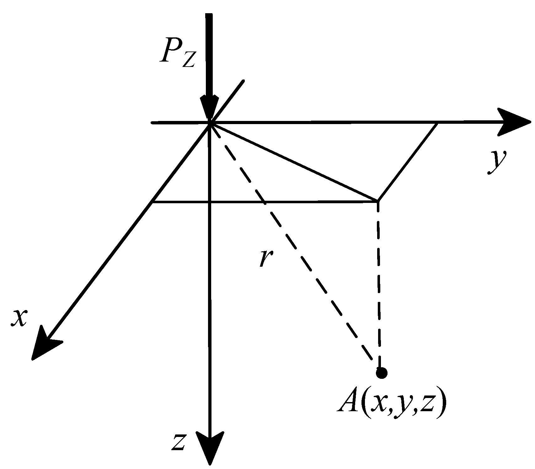
2.1. Analytical Solution of Penetration Force and Displacement in Infinite Space

According to the solution of Kelvin problem, the relationship between the vertical displacement and the vertical force is shown in Equation (1) and Figure 1:
u z = 1 2 ( 1 υ ) ( 1 + υ ) 4 π E [ 2 ( 1 2 υ ) r + 1 r + z 3 r 3 ] P z
among them, Where u z is the vertical displacement, r = x 2 + y 2 + z 2 , E is the compression modulus of soil, υ is the Poisson’s ratio of the soil, and P z is the penetration force of the pile tip.
Taking the center of the coordinate axis as the center of the pile tip and in the infinite body, the vertical displacement is simplified as:
u z = 1 2 ( 1 υ ) ( 1 + υ ) 4 π E [ 2 ( 1 2 υ ) r + 1 r + z 3 r 3 ] P z
Among r = x 2 + y 2 .

2.2. Analytical Solution of Pile Tip Stress in Infinite Space

The force of the Kelvin problem is a vertical concentrated force, and the vertical displacement caused by multiple vertical concentrated forces can be obtained by superposition. To study the penetrating force at the pile tip, it is not possible to use the method of superposition of a limited number of vertical concentrated forces, it is necessary to use the stress distribution function, assuming the stress distribution function:
p = p 0 ( 1 r 2 a 2 ) 1 2
D p d x d y = P z
Among them, p 0 is the compressive stress amplitude, a is the radius of the pile tip, r is the distance from any point to the axis, and D is the area of the pile tip with radius a.
u z = ( 1 + υ ) 2 ( 1 υ ) ( 3 2 υ ) 4 π E D p ( x , y ) r d x d y
Due to the rotational symmetry of the pile tip, the vertical displacement of a point is only related to the distance r from the center point. For this purpose, only the displacement of the point on the x axis needs to be calculated. Take point A coordinate ( x , y ) on the x axis and the B coordinate ( x , y ) at any point on the pile tip, according to the positional relationship shown in Figure 2.
Stress at point B:
p ( s , φ ) = p 0 ( 1 r 2 + s 2 + 2 r s cos φ a 2 ) 1 2 = p 0 a ( a 2 r 2 s 2 2 r s cos φ )
The vertical displacement of point A is equal to the superposition of the influence of any point on the pile tip, according to Equation (6):
u z = ( 1 + υ ) 2 ( 1 υ ) ( 3 2 υ ) 4 π E p 0 a 0 2 π ( 0 s 1 ( a 2 r 2 2 r s cos φ s 2 ) 1 2 d s ) d φ
Among them, s 1 is the positive root of a 2 r 2 2 r s cos φ s 2 = 0 , 0 s 1 ( a 2 r 2 2 r s cos φ s 2 ) 1 2 d s = π 2 arctan [ r cos φ ( a 2 r 2 ) 1 2 ] .
Equation (7) calculates:
u z = ( 1 + υ ) ( 1 υ ) ( 3 2 υ ) 8 E p 0 a π = c o n s t a n t
The vertical displacement of each point in the contact area of the closed-ended pile tip is consistent with the displacement coordination condition.
Calculated by Equation (4) Exchange points:
P z = 0 a p 0 ( 1 r 2 a 2 ) 1 2 2 π r d r = 2 π p 0 a 2
The simultaneous Equations (8) and (9) yield:
u z = ( 1 + υ ) ( 1 υ ) ( 3 2 υ ) 16 P z E a

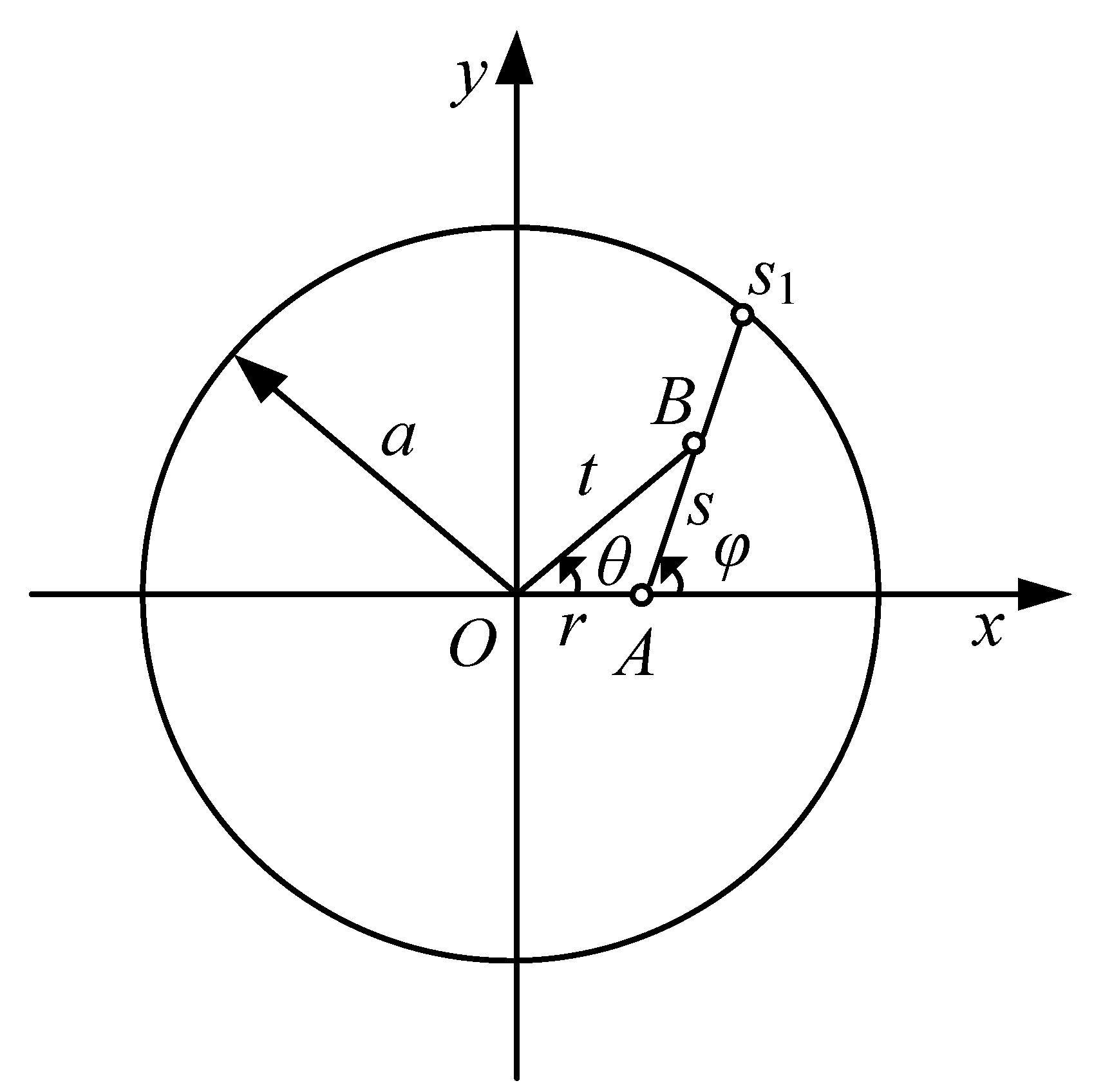
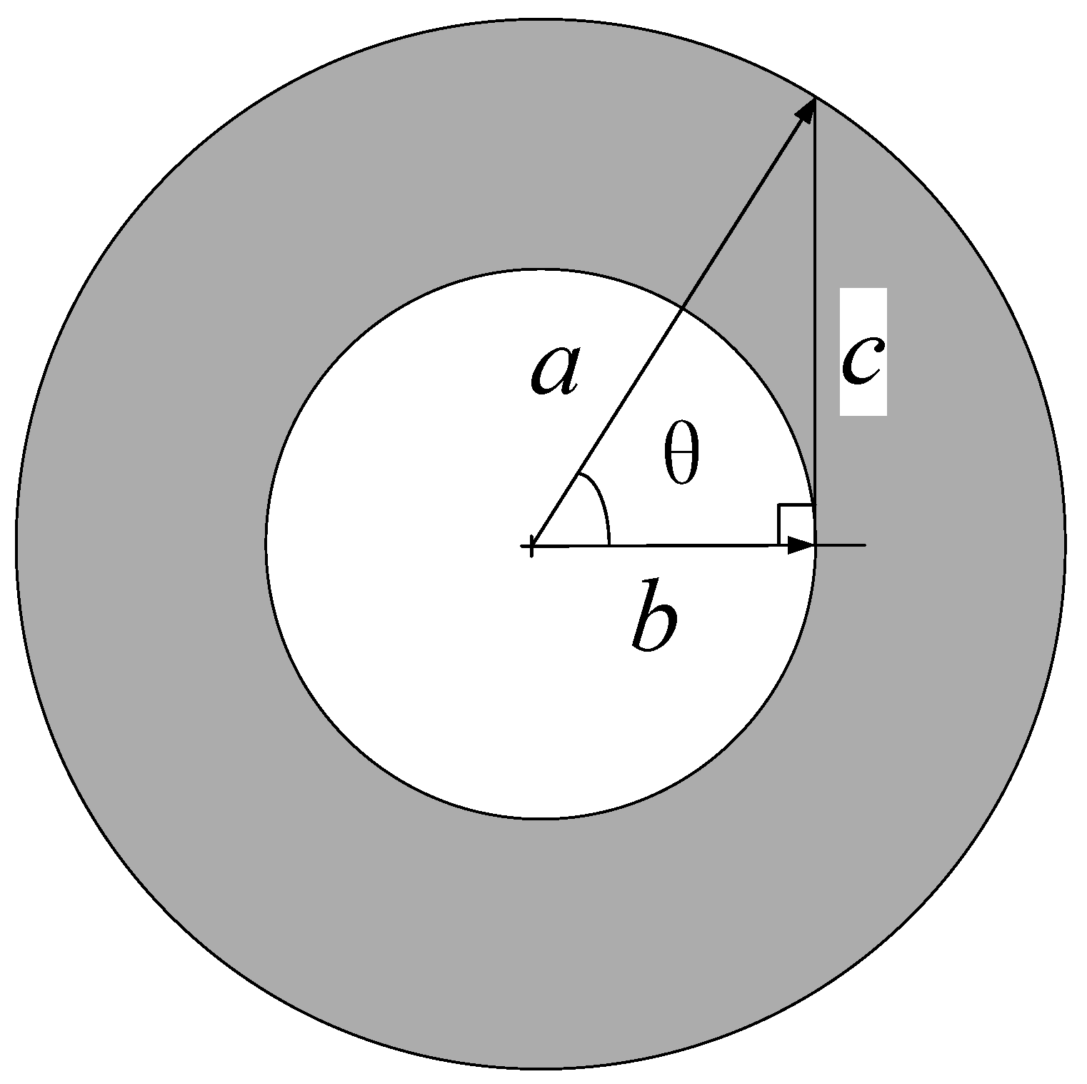
2.3. Stress Distribution of Closed Soil Plug

Since, the displacement of the pile tip is the same under closed soil plug, the stress distribution can be calculated using Equation (1). However, the action range needs to be calculated separately. The section of the soil plug is shown in Figure 3.
P Z- p l u g = 0 b p 0 ( 1 r 2 a 2 ) 1 2 2 π r d r
Exchange points t = 1 r 2 a 2 , d r = a 2 2 r d t .
P Z- p l u g = p 0 π a 2 1 1 b 2 a 2 t 1 2 d t = 2 π a 2 p 0 ( 1 a 2 b 2 a 2 ) = 2 π a 2 p 0 ( 1 sin θ ) = P Z ( 1 sin θ )
σ P Z ¯ = P Z π a 2 ,   σ P Z -plug ¯ = P Z -plug π b 2 = P Z ( 1 sin θ ) π b 2 ,   σ P Z -pipe ¯ = P Z P Z -plug π a 2 π b 2 = P Z sin θ π a 2 π b 2 σ P Z -plug ¯ σ P Z ¯ = P Z -plug π b 2 π a 2 P Z = P Z ( 1 sin θ ) π b 2 π a 2 P Z = P Z ( 1 c a ) π b 2 π a 2 P Z = a 2 a c b 2 = a 2 a 2 a c a 2 b 2 a 2 = 1 sin θ cos 2 θ = 1 sin θ ( 1 sin θ ) ( 1 + sin θ ) = 1 1 + sin θ
σ P Z- p i p e ¯ σ P Z ¯ = P Z sin θ π a 2 π b 2 π a 2 P Z = sin θ a 2 a 2 b 2 = sin θ 1 cos 2 θ = 1 sin θ
When the soil plug is closed, the proportion of the penetration force of the soil plug is directly related to the diameter of the pile tip and the pipe thickness. With a fixed diameter, the greater the pipe thickness and the larger is θ and smaller is the proportion of ultimate load stress of the soil plug. The greater is the proportion of the bearing stress of the pipe (as shown in Figure 4).

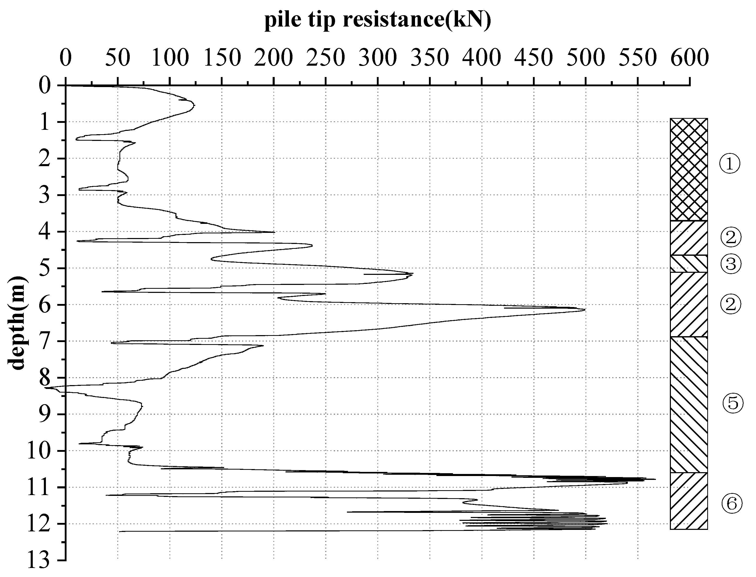
3. Penetration Test of Closed-Ended Pile
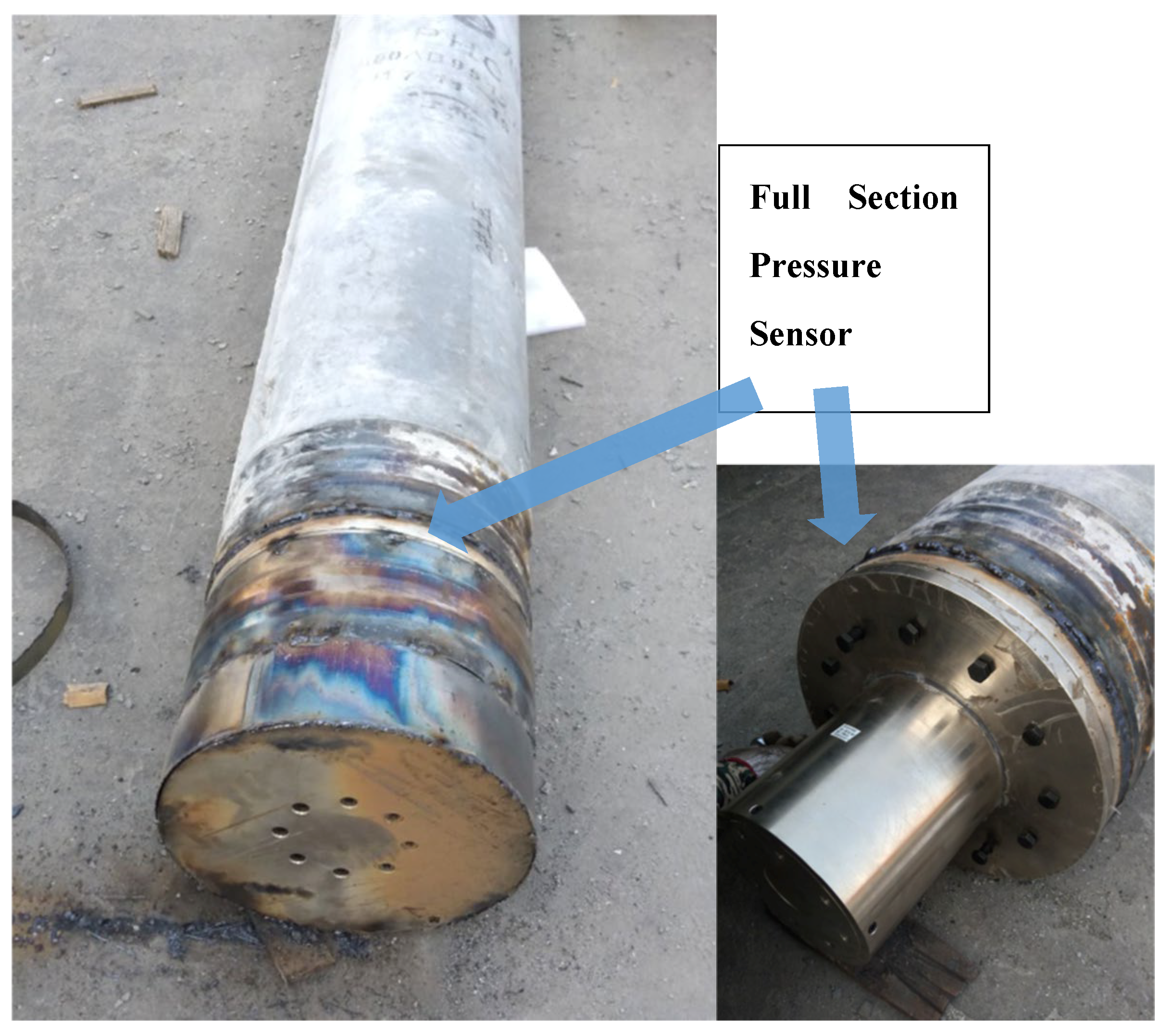
3.1. Test Overview

To verify the relationship between the bearing capacity and displacement of Closed soil plugs, an on-site static pressure pile test was carried out. The test site is located in Dongying, Shandong Province, about 20 km away from the Yellow River. It belongs to the Yellow River impact plain and has clear soil layers. It is mainly composed of silt and silty clay. The soil layer is shown in Table 1. The pile diameter is 400 mm and the pile length is 12 m. A 100t full-section pressure sensor is placed at a pile tip. In order to minimize error due to signal attenuation caused by long cable (60 m), a RS-485 signal transmission is used. Static pressure penetration was applied with the average penetration speed is 1.2 m/min. The test position and sensor are shown in Figure 5.

3.2. Test Results

The penetration test of the static pressure pile is divided into 9 strokes. The penetration depth of each stroke is about 1.4 m. The relationship between the resistance of the pile tip and the penetration depth is shown in Figure 6. After the start of static pressure penetration, there is a stage of stored force pressurization at each stroke before the pile tip pierces the soil layer. During this period, the deformation of the soil body is mainly compression, and the settlement is less. When the pile tip force breaks through the critical value, the pile foundation quickly penetrates the soil layer. Table 2 shows the bearing capacity of pile tips at each stroke.

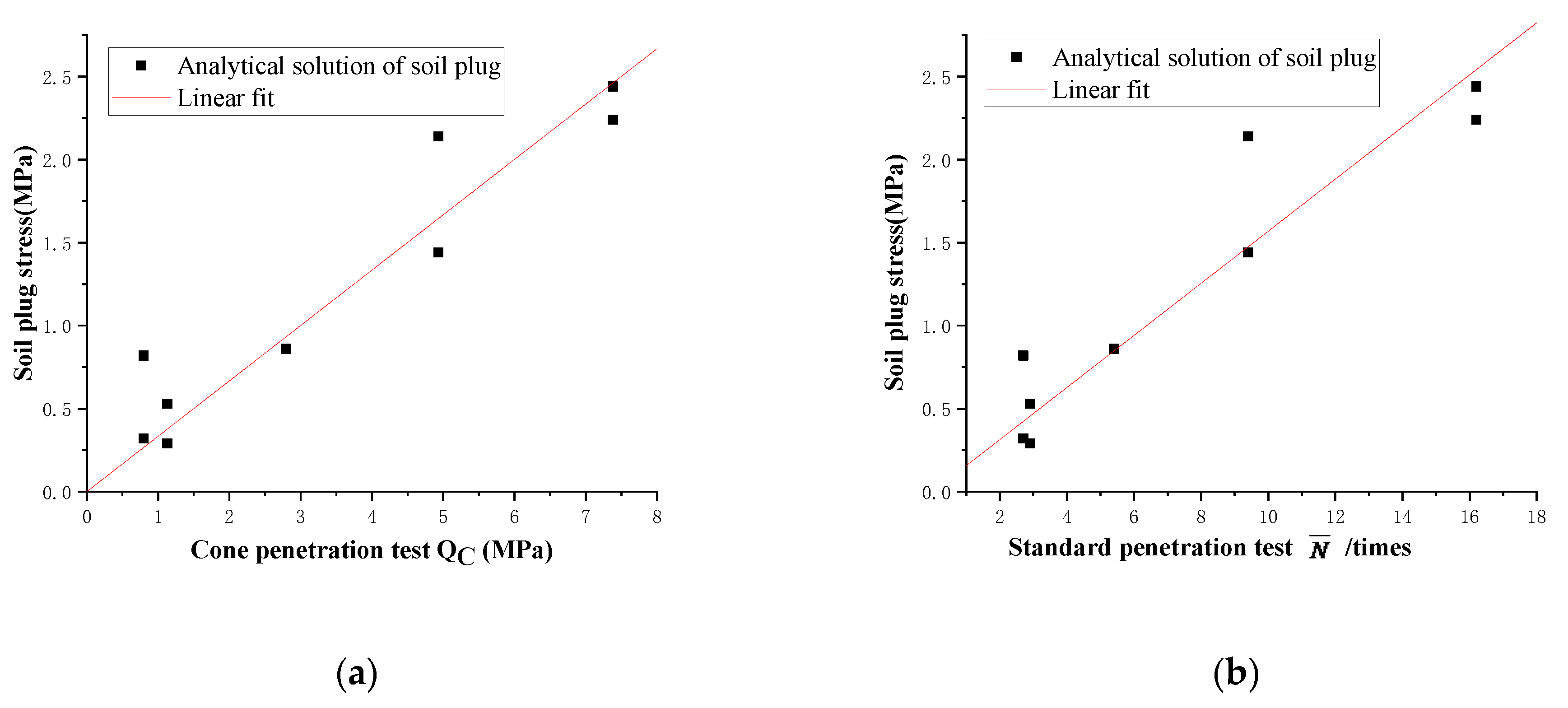
4. Relationship Between Soil Plug Resistance and Soil Layer

According to the relationship (Figure 6), between the penetration resistance at the pile tip and the soil layer, the initial penetration resistance in the soil layer is greater than the secondary penetration in the soil layer. After the initial penetration into the soil layer, the soil around the pile undergoes large deformation, and the part of soil layer, where it penetrates, again has been affected by the previous penetration. A similar phenomenon occurs in the strokes 1~2, 6~7, 8~9. It is proved that the maximum resistance of the layered soil pile tip occurs at the peak value generated, when the layered soil penetrates initially.
According to Equation (12), the analytical solution of closed soil plug is calculated and listed in Table 2. The Equation (15) obtained by fitting the analytical solution of the closed soil plug stress in Table 2 to CPT has a good correlation, R2 = 0.96502.
The Equation (16) obtained by fitting the analytical solution of the closed soil plug stress in Table 2 to SPT has a good correlation, R2 = 0.96176, as shown in Figure 7. This test pile passes through the plain fill, silt, and silty clay, and it can be considered that Equations (15) and (16) have good applicability to these three soil layers.
σ P Z -plug ¯ = 0 . 33357 Q C
σ P Z -plug ¯ = 0 . 15688 N ¯

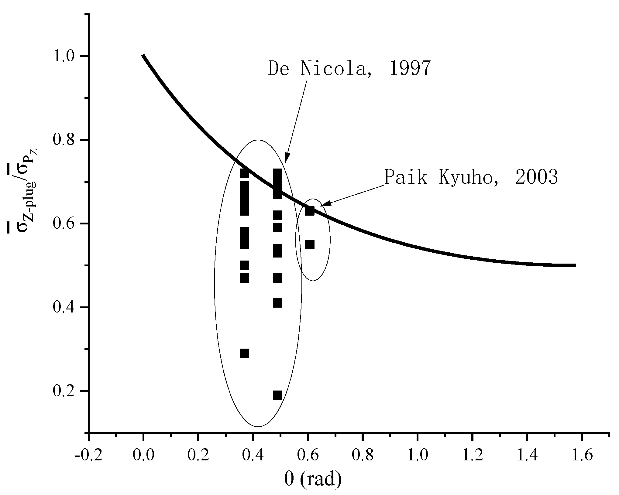
5. Analytical Verification

When the soil plug is closed, the displacement of each point at pile tip is the same. Equation (8) derived from Equation (3) can ensure that the displacement of each point at pile tip is consistent. It can be seen from Equation (3) that the force of each point at pile tip is related to the distance from the center point. Many scholars have conducted theoretical derivation and experimental research on the formation of soil plugs. However, it is more difficult to separate the pile pipe stress and the soil plug stress at pile tip. Only a few scholars have successfully distinguished it, the experimental data of De Nicola [13] and Paik Kyuho [2] are shown in Table 3, Table 4 and Table 5, but it is still difficult to test the values of soil plug stress and plie pipe stress at pile tip when the soil plug is closed. During the penetration of the pile, the experimental value of the stress distribution between the soil plug and the pipe still has a certain reference.
Table 3, Table 4 and Table 5 lists the parameters of the open-ended pile and the results calculated by Equations (13) and (14). The results are made into Figure 8. According to the results shown in Figure 8, more than 90% of the test data are within the scope of the analytical solution proposed in this paper, the formulas in this paper can be used as a reference for the calculation of soil plug stress.

6. Conclusions

Due to the difficulty of the test, only a few tests measured the pipe stress and the soil plug stress at the same time, which brought great difficulty to the verification work of this paper. If the discrete element method can be used to simulate the soils and multi-size piles better, the force at pile tip will no longer be difficult to distribute when the pipe pile is jacked or the soil plug is closed, which is also a new research direction.
This study presents a new analytical solution for exploring relationship of bearing capacity of plug with that of properties of soil layers. Using the solution of the Kelvin problem in infinite space and the analytical solution obtained by the plane stress distribution function, the proportion of the penetration force of the soil plug is directly related to the diameter of the pile tip and the pipe thickness. When the diameter is fixed, the greater the pipe thickness, the smaller the proportion of the ultimate load-bearing stress of the soil plug. Through the static pressure penetration test of the pile foundation installed with a full-section pressure sensor, the obtained formula can be well used in the bearing capacity of the closed soil plug. The results show that the bearing capacity of the soil plug is closely related to the properties of the soil layer. The analytical solution of the ultimate bearing capacity of the soil plug has a linear relationship with the formation parameters SPT, CPT. The conclusion of this article can provide a reference for the design.

Author Contributions

Conceptualization, methodology and writing—original draft preparation, S.Y.; writing—review and editing, J.L., A.G. and M.Z., funding acquisition, J.L. and M.Z. All authors have read and agreed to the published version of the manuscript.

Funding

This research was funded by the National Natural Science Foundation of China (Grant No. 41772318,51778312), Shandong Key Research and Development Plan (2017GSF20107), Cooperative Innovation Center of Engineering Construction and Safety in Shandong Blue Economic Zone, Open Fund of State Key Laboratory of Coastal and Offshore Engineering (LP1712), Ministry of Housing and Urban-Rural Development of China (2014-K3-026).

Acknowledgments

Thanks to Liu Chenxi from Logistics University of People’s Armed Police Force for supporting this work.

Conflicts of Interest

The authors declare no conflict of interest.

References

  1. Yang, S.C.; Zhang, M.Y.; Wang, Y.H.; Sang, S.K.; Miao, D.Z. Field test on pile tip resistance of closed-end jacked pipe pile penetrating into layered foundation. Rock Soil. Mech. 2018, 39, 91–99. [Google Scholar]
  2. Yang, S.C.; Liu, J.L.; Zhang, M.Y. Analytical solution and field test of critical bearing capacity and settlement of pile tip. Civ. Eng. J. Staveb. Obz. 2020, 1, 61–73. [Google Scholar] [CrossRef]
  3. Aleksandrova, N.A.; Kondratenko, A.S. Calculation of Pipe Movement with Soil Plug under Longitudinal Impact. J. Min. Sci. 2019, 54, 384–396. [Google Scholar] [CrossRef]
  4. Paik, K.; Salgado, R.; Lee, J.; Kim, B. Behavior of Open- and Closed-Ended Piles Driven Into Sands. J. Geotech. Geoenviron. Eng. 2003, 129, 296–306. [Google Scholar] [CrossRef]
  5. Randolph, M.; Leong, E.; Houlsby, G. One-dimensional analysis of soil plugs in pipe piles. Geotechnique 1991, 41, 587–598. [Google Scholar] [CrossRef]
  6. Liu, J.; Guo, Z.; Han, B. Load Transfer of Offshore Open-Ended Pipe Piles Considering the Effect of Soil Plugging. J. Mar. Sci. Eng. 2019, 7, 313. [Google Scholar] [CrossRef] [Green Version]
  7. Liu, H.; Wu, W.; Jiang, G.; El Naggar, M.H.; Mei, G.; Liang, R. Influence of soil plug effect on the vertical dynamic response of large diameter pipe piles. Ocean Eng. 2018, 157, 13–25. [Google Scholar] [CrossRef]
  8. Henke, S.; Grabe, J. Field measurements regarding the influence of the installation method on soil plugging in tubular piles. Acta Geotech. 2012, 8, 335–352. [Google Scholar] [CrossRef]
  9. Tran, K.T.; McVay, M.; Herrera, R.; Lai, P. Estimating static tip resistance of driven piles with bottom pile instrumentation. Can. Geotech. J. 2012, 49, 381–393. [Google Scholar] [CrossRef]
  10. Kou, H.-l.; Li, W.; Chu, J.; Yang, D.-l. Model tests on open-ended concrete pipe piles jacked in sand. Mar. Georesour. Geotechnol. 2019, 1–8. [Google Scholar] [CrossRef]
  11. Fattah, M.Y.; Al-Soudani, W.H.S. Bearing capacity of open-ended pipe piles with restricted soil plug. Ships Offshore Struct. 2015, 11, 501–516. [Google Scholar] [CrossRef]
  12. Malik, A.A.; Kuwano, J.; Tachibana, S.; Maejima, T. End bearing capacity comparison of screw pile with straight pipe pile under similar ground conditions. Acta Geotech. 2016, 12, 415–428. [Google Scholar] [CrossRef]
  13. Doherty, P.; Gavin, K. Shaft Capacity of Open-Ended Piles in Clay. J. Geotech. Geoenvironm. Eng. 2011, 137, 1090–1102. [Google Scholar] [CrossRef] [Green Version]
  14. Yan, S.-W.; Zhou, Q.-H.; Liu, R.; Dong, W. Pit bearing capacity effect on status of soil plug during pile driving in ocean engineering. China Ocean Eng. 2011, 25, 295–304. [Google Scholar] [CrossRef]
  15. De Nicola, A.; Randolph, M. The plugging behaviour of driven and jacked piles in sand. Geotechnique 1997, 47, 841–856. [Google Scholar] [CrossRef]
  16. Henke, S.; Grabe, J. Numerical investigation of soil plugging inside open-ended piles with respect to the installation method. Acta Geotech. 2008, 3, 215–223. [Google Scholar] [CrossRef]
  17. Paik, K.H.; Lee, S.R. Behavior of soil plugs in open-ended model piles driven into sands. Mar. Georesour. Geotechnol. 2008, 11, 353–373. [Google Scholar] [CrossRef]
  18. Liu, C.; Tang, X.; Wei, H.; Wang, P.; Zhao, H. Model Tests of Jacked-Pile Penetration into Sand Using Transparent Soil and Incremental Particle Image Velocimetry. KSCE J. Civ. Eng. 2020, 24, 1128–1145. [Google Scholar] [CrossRef]
  19. Randolph, M.; May, M.; Leong, E.; Hyden, A.; Murff, J. Soil plug response in open-ended pipe piles. J. Geotech. Eng. 1992, 118, 743–759. [Google Scholar] [CrossRef]
  20. Bhattacharya, S.; Carrington, T.; Aldridge, T. Observed increases in offshore pile driving resistance. Proceedings of the Institution of Civil Engineers. Geotech. Eng. 2009, 162, 71–80. [Google Scholar] [CrossRef] [Green Version]
  21. Yu, F.; Yang, J. Base Capacity of Open-Ended Steel Pipe Piles in Sand. J. Geotech. Geoenviron. Eng. 2012, 138, 1116–1128. [Google Scholar] [CrossRef] [Green Version]
  22. Tang, C.; Phoon, K.-K. Characterization of model uncertainty in predicting axial resistance of piles driven into clay. Can. Geotech. J. 2019, 56, 1098–1118. [Google Scholar] [CrossRef]
  23. Ahmadi, S.F.; Eskandari, M. Axisymmetric circular indentation of a half-space reinforced by a buried elastic thin film. Math. Mech. Solids 2013, 19, 703–712. [Google Scholar] [CrossRef]
  24. Ahmadi, S.F.; Eskandari, M. Vibration Analysis of a Rigid Circular Disk Embedded in a Transversely Isotropic Solid. J. Eng. Mech. 2014, 140. [Google Scholar] [CrossRef]
  25. Eskandari, M.; Samea, P.; Ahmadi, S.F. Axisymmetric time-harmonic response of a surface-stiffened transversely isotropic half-space. Meccanica 2016, 52, 183–196. [Google Scholar] [CrossRef]
  26. Ai, Z.Y.; Liu, C.L. Dynamic impedance of a pipe pile in layered soils under vertical excitations. Soil Dyn. Earthq. Eng. 2017, 97, 387–394. [Google Scholar] [CrossRef]
  27. Ko, J.; Jeong, S. Plugging effect of open-ended piles in sandy soil. Can. Geotech. J. 2015, 52, 535–547. [Google Scholar] [CrossRef]
  28. Jeong, S.; Ko, J.; Won, J.; Lee, K. Bearing capacity analysis of open-ended piles considering the degree of soil plugging. Soils Found. 2015, 55, 1001–1014. [Google Scholar] [CrossRef] [Green Version]
  29. Xu, M.; Ni, P.; Mei, G.; Zhao, Y. Load-settlement behaviour of bored piles with loose sediments at the pile tip: Experimental, numerical and analytical study. Comput. Geotech. 2018, 102, 92–101. [Google Scholar] [CrossRef]
  30. Liu, J.W.; Cui, L.; Zhu, N.; Han, B.; Liu, J. Investigation of cyclic pile-sand interface weakening mechanism based on large-scale CNS cyclic direct shear tests. Ocean. Eng. 2019, 194, 11. [Google Scholar] [CrossRef]
  31. Leong, E.; Randolph, M. Finite element analyses of soil plug response. Int. J. Numer. Anal. Methods Geomech. 1991, 15, 121–141. [Google Scholar] [CrossRef]
  32. Liyanapathirana, D.; Deeks, A.; Randolph, M. Numerical analysis of soil plug behaviour inside open-ended piles during driving. Int. J. Numer. Anal. Methods Geomech. 1998, 22, 303–322. [Google Scholar] [CrossRef]
  33. Liyanapathirana, D.S.; Deeks, A.J.; Randolph, M.F. Numerical modelling of the driving response of thin-walled open-ended piles. Int. J. Numer. Anal. Methods Geomech. 2001, 25, 933–953. [Google Scholar] [CrossRef]
  34. Ko, J.; Jeong, S.; Lee, J.K. Large deformation FE analysis of driven steel pipe piles with soil plugging. Comput. Geotech. 2016, 71, 82–97. [Google Scholar] [CrossRef]
  35. Guo, Y.; Yu, X.B. Design and analyses of open-ended pipe piles in cohesionless soils. Front. Struct. Civ. Eng. 2016, 10, 22–29. [Google Scholar] [CrossRef]
  36. Liu, J.; Duan, N.; Cui, L.; Zhu, N. DEM investigation of installation responses of jacked open-ended piles. Acta Geotech. 2019, 14, 1805–1819. [Google Scholar] [CrossRef]
  37. Chen, F.; Lin, Y.; Dong, Y.; Li, D. Numerical investigations of soil plugging effect inside large-diameter, open-ended wind turbine monopiles driven by vibratory hammers. Mar. Georesour. Geotechnol. 2019, 38, 83–96. [Google Scholar] [CrossRef]
  38. Liu, J.; Guo, Z.; Zhu, N.; Zhao, H.; Garg, A.; Xu, L.; Liu, T.; Fu, C. Dynamic Response of Offshore Open-Ended Pile under Lateral Cyclic Loadings. J. Mar. Sci. Eng. 2019, 7, 128. [Google Scholar] [CrossRef] [Green Version]
  39. Li, L.; Wu, W.; Hesham El Naggar, M.; Mei, G.; Liang, R. DEM analysis of the sand plug behavior during the installation process of open-ended pile. Comput. Geotech. 2019, 109, 23–33. [Google Scholar] [CrossRef]
  40. Wang, T.; Zhang, Y.; Bao, X.; Wu, X. Mechanisms of soil plug formation of open-ended jacked pipe pile in clay. Comput. Geotech. 2020, 118, 103334. [Google Scholar] [CrossRef]
  41. Yang, S.; Liu, J.; Xu, L.; Zhang, M.; Jeng, D.-S. A New Approach to Explore the Surface Profile of Clay Soil Using White Light Interferometry. Sensors 2020, 20, 3009. [Google Scholar] [CrossRef] [PubMed]
Figure 1. Schematic diagram of Kelvin problem.
Jmse 08 00490 g001
Figure 2. Position relations of various points in the pile tip area. Among them, A is any point on the x axis in the circle, B is any point in the circle, a is the diameter, s is the distance between the two points of A and B, s1 is the distance between the extension line of AB and the circle at a point, and t is the distance from B to the center O, φ is the angle between AB and the x axis, and θ is the angle between OB and the x axis.
Jmse 08 00490 g002
Figure 3. Soil plug section. Among them, a is the outer diameter of the pile, b is the inner diameter of the pile, and c is the length obtained by ab and the Pythagorean theorem, θ is the angle between a and b.
Jmse 08 00490 g003
Figure 4. Stress ratio: (a) Ratio of soil plug stress to penetration stress; (b) Ratio of pipe stress to penetration stress.
Jmse 08 00490 g004
Figure 5. Full Section Pressure Sensor.
Jmse 08 00490 g005
Figure 6. Relationship between resistance and depth.
Jmse 08 00490 g006
Figure 7. Linear fitting: (a) Soil plug stress and CPT linear fitting; (b) Soil plug stress and SPT linear fitting.
Jmse 08 00490 g007
Figure 8. Verification of soil plug to total stress ratio.
Jmse 08 00490 g008
Table 1. Stratigraphic parameters.
Depth/mSoil LayerCompression Modulus Es1-2 /MPaVoid Ratio eWater Content w/%Cone Penetration Test QC/MPa Standard   Penetration   Test   N ¯ /Times
0–3.08①Plain fill(q4ml)4.190.86730.41.1302.9
3.08–4.58②Silt(q4al)8.550.80327.72.7965.4
4.58–5.08③Silty clay(q4al)4.900.87630.50.9283.4
5.08–6.98④Silt(q4al)9.110.79428.04.9309.4
6.98–10.38⑤Silty clay(q4al)4.670.89531.50.7992.7
10.38–13.88⑥Silt(q4al)10.540.79328.07.37916.2
Table 2. Pile penetration parameters.
Pile Penetration StrokePeak Penetration Resistance/kNAnalytical Solution of Soil Plug/kNThrough the Soil LayerSoil Layer at Pile TipCone Penetration Test QC/MPa Standard   Penetration   Test   N ¯ /Times
Stroke 1124(0.99) 1106(0.53)1.1302.9
Stroke 267(0.53)57(0.29)1.1302.9
Stroke 3201(1.60)171(1.86)①②2.7965.4
Stroke 4334(2.66)284(1.44)②–④4.939.4
Stroke 5499(3.97)425(2.14)4.939.4
Stroke 6190(1.51)162(0.82)④⑤0.7992.7
Stroke 774(0.59)63(0.32)0.7992.7
Stroke 8567(4.51)483(2.44)⑤⑥7.37916.2
Stroke 9521(4.15)443(2.24)7.37916.2
1 The value in the table () is the corresponding stress value (MPa).
Table 3. De Nicola open-ended test results analysis.
Internal Diameter
(mm)
Outer Diameter
(mm)
Pipe Thickness
(mm)
a
(mm)
b
(mm)
c
(mm)
sinθ
14.9160.5587.452.920.36
Pipe stress (MPa)Soil plug stress (MPa)Total stress (MPa)Test value of soil plug to total stress ratioTheoretical value of soil plug to total stress ratioTest value of pipe to total stress ratioTheoretical value of pipe to total stress ratio
8.452.044.060.500.732.082.74
8.543.85.290.721.61
4.90.561.930.292.54
7.372.063.730.551.98
7.522.544.420.571.70
11.913.646.240.581.91
10.223.895.880.661.74
14.293.076.60.472.17
11.914.887.090.691.68
8.562.064.110.502.08
12.973.956.790.581.91
23.238.5513.170.651.76
25.9810.0615.070.671.72
23.728.3813.210.631.80
Table 4. De Nicola sleeve-ended test results analysis.
Internal Diameter
(mm)
Outer Diameter
(mm)
Pipe Thickness
(mm)
a
(mm)
b
(mm)
c
(mm)
14.1160.9587.053.78
Pipe stress (MPa)Soil plug stress (MPa)Total stress (MPa)Test value of soil plug to total stress ratioTheoretical value of soil plug to total stress ratioTest value of pipe to total stress ratio
4.90.42.140.190.682.29
7.372.244.220.531.75
8.542.24.650.471.84
8.514.145.830.711.46
10.252.25.310.411.93
14.341.26.280.192.28
11.914.597.420.621.61
11.914.257.210.591.65
23.627.4713.710.541.72
23.6111.7316.320.721.45
8.323.815.550.691.50
12.665.58.270.671.53
23.7410.715.740.681.51
Table 5. Paik Kyuho open-ended test results analysis.
Internal Diameter
(mm)
Outer Diameter
(mm)
Pipe Thickness
(mm)
a
(mm)
b
(mm)
c
(mm)
sinθ
29235632178146101.820.57
Pipe stress (MPa)Soil plug stress (MPa)Total stress (MPa)Test value of soil plug to total stress ratioTheoretical value of soil plug to total stress ratioTest value of pipe stress to total stress ratioTheoretical value of pipe stress to total stress ratio
17.595.029.130.550.641.931.75
13.823.967.180.551.50
15.755.578.900.631.77
18.705.359.710.551.92
22.016.2911.430.551.93

