Features of Earthquake-Induced Seabed Liquefaction and Mitigation Strategies of Novel Marine Structures


Abstract
:1. Introduction
2. Seismic Field Investigations in Marine Engineering
3. Features of Earthquake-Induced Seabed Liquefaction
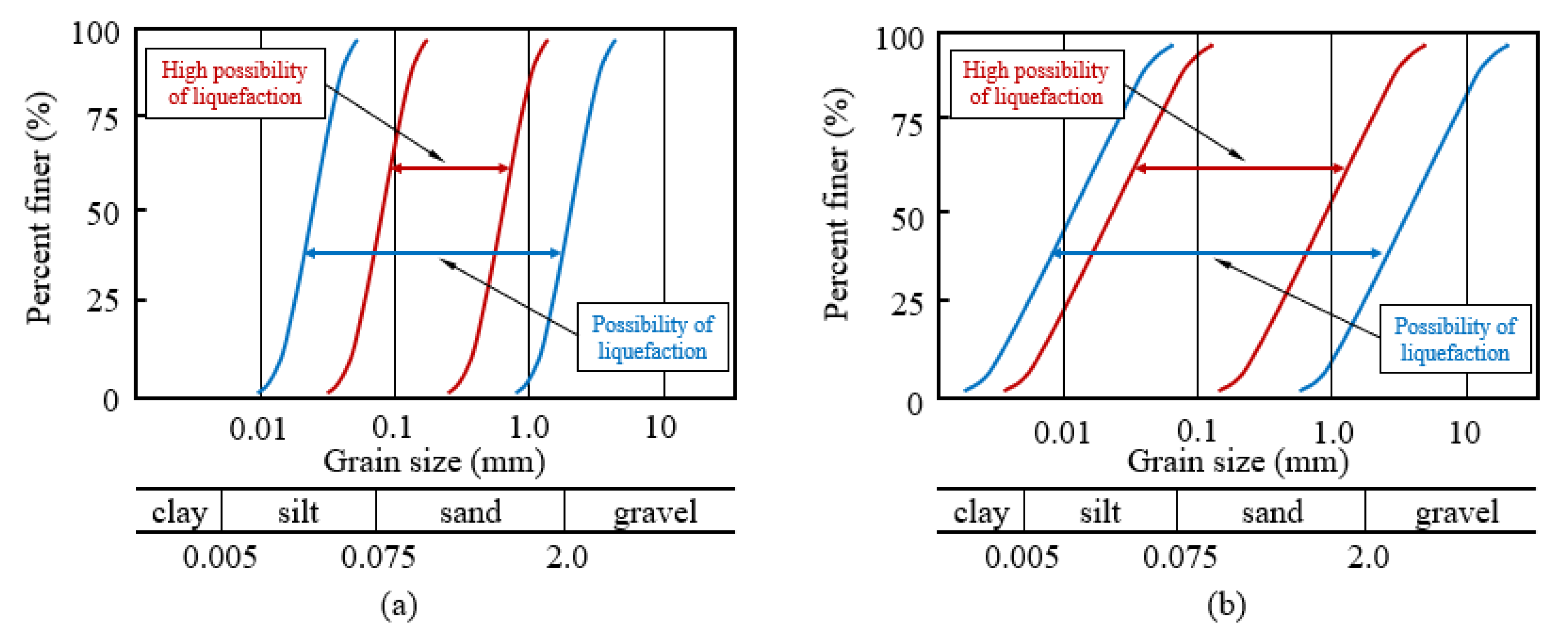
3.1. Marine Deposits Layer
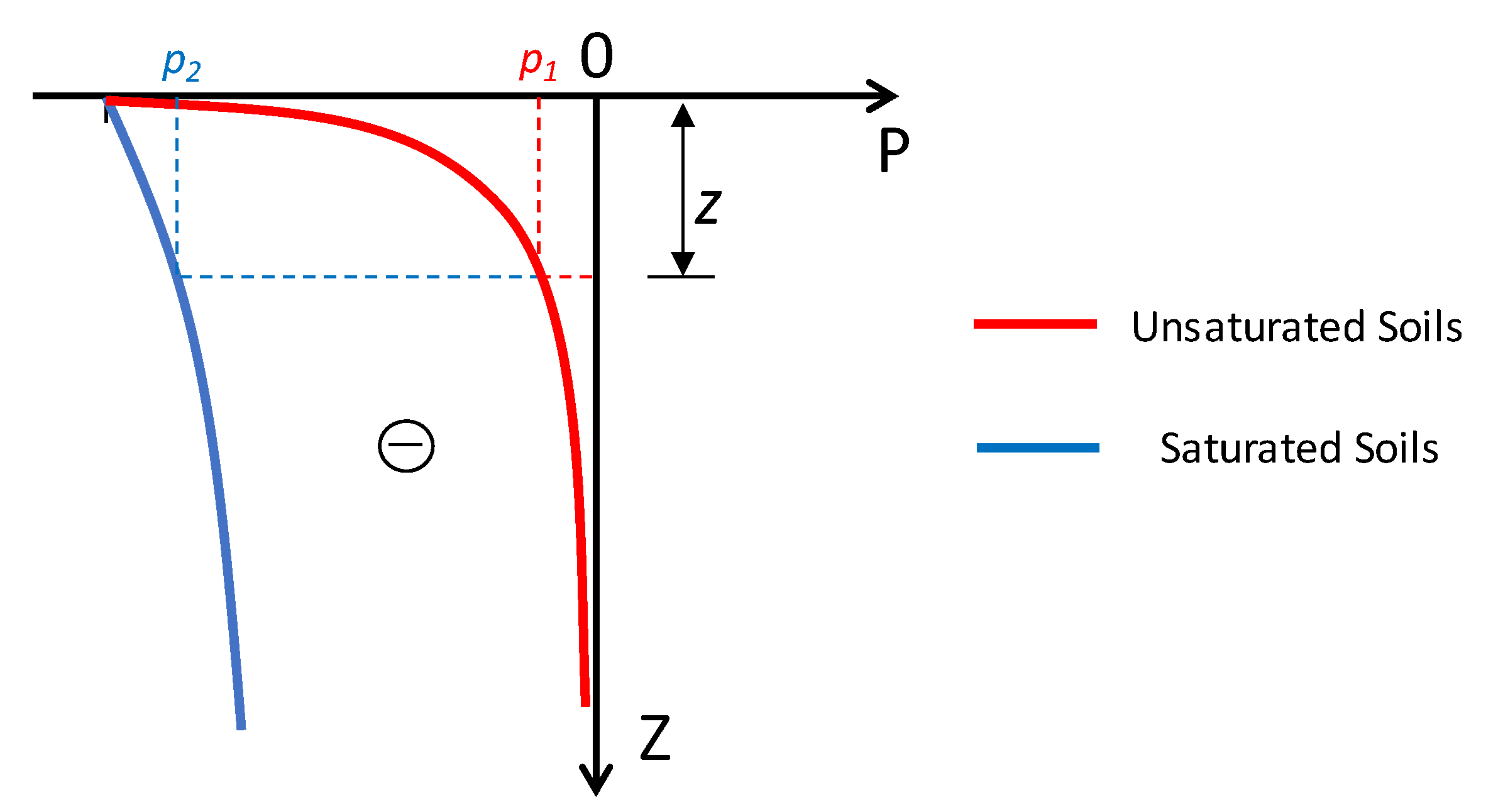
3.2. Influence of Sea Water
3.3. Influence of Submarine Gas Composition
4. Seismic Liquefaction Mitigation Strategies of Novel Marine Structures
4.1. Conventional Liquefaction-Resistance Measures
4.2. Liquefaction-Resistance Measures of New Marine Structures
4.2.1. Non-Supported Structures
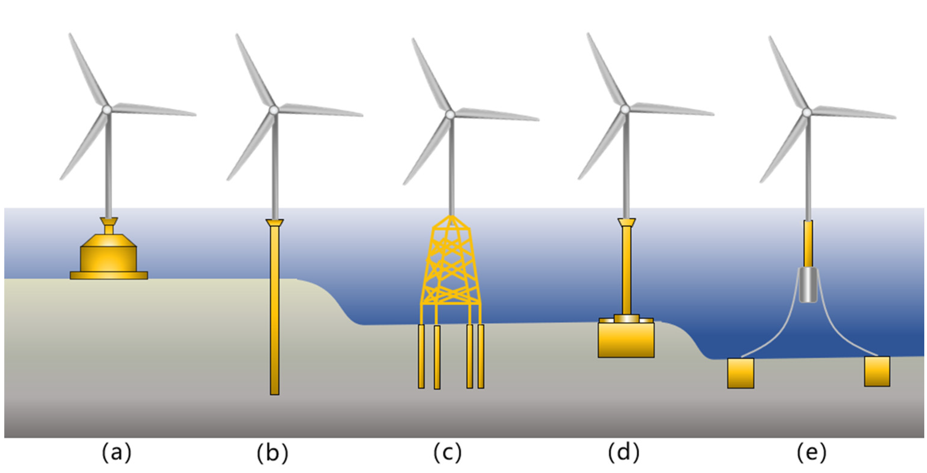
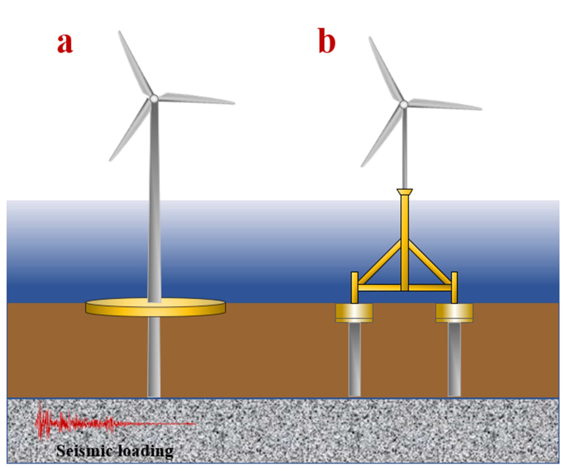
4.2.2. Foundation-Supported Structures
4.2.3. An Example on Site
5. Conclusions
- (1)
- This article summarizes seismic liquefaction field investigations in marine engineering to provide a systematic understanding of the historical cases published over recent decades. These cases show that seismic-induced liquefaction has a huge impact on marine structures and should be taken into account when designing in the future.
- (2)
- Seabed seismic liquefaction has different characteristics to those seen in land seismic liquefaction. The effect of seawater and trapped or escaping gas on seismic liquefaction is not negligible; seabed soil layers are more prone to liquefaction than onshore soil layers, and the liquefied area may be larger than on land.
- (3)
- Many novel improvements of foundation structures that reduce liquefaction damage in marine engineering have been proposed in recent years; these include the hybrid monopile foundation, umbrella suction anchor foundation, and anchor piles with suction for floating foundations, etc. Experimental and numerical analyses show that these new marine structures have better liquefaction-resistance performance than traditional structures and need to be further promoted in engineering design.
- (4)
- Having the advantages of low cost, fast construction and reusability, the suction bucket modification used in OWTs is the most widely studied concept nowadays. However, the monopile is the main foundation type for OWTs in current use. The hybrid monopile concept can be used to strengthen existing monopile structures to increase their liquefaction resistance. In addition, it is foreseeable that the research on floating foundations is likely to expand in the coming years, and new liquefaction-resistant structures with floating foundations may become the next research hotspot.
- (5)
- Many other marine structures have been designed while taking into account seismic liquefaction. However, the prevention of submarine seismic liquefaction damage is still facing many difficulties and challenges. Thus, we should give priority to marine geological disaster prevention in project site selection and design to minimize the damage caused by seismic liquefaction around marine structures.
Author Contributions
Funding
Acknowledgments
Conflicts of Interest
References
- Willis, D.J.; Niezrecki, C.; Kuchma, D.; Hines, E.; Arwade, S.R.; Barthelmie, R.J.; DiPaola, M.; Drane, P.J.; Hansen, C.J.; Inalpolat, M.; et al. Wind energy research: State-of-the-art and future research directions. Renew. Energy 2018, 125, 133–154. [Google Scholar] [CrossRef]
- Wu, X.; Hu, Y.; Li, Y.; Yang, J.; Duan, L.; Wang, T.; Adcock, T.; Jiang, Z.; Gao, Z.; Lin, Z.; et al. Foundations of offshore wind turbines: A review. Renew. Sustain. Energy Rev. 2019, 104, 379–393. [Google Scholar] [CrossRef] [Green Version]
- Zhang, M.; Zhang, W.; Huang, Y.; Cai, Y.; Shen, S. Failure mechanism of submarine slopes based on the wave flume test. Nat. Hazards 2019, 96, 1249–1262. [Google Scholar] [CrossRef]
- Jia, Y.; Zhu, C.; Liu, L.; Wang, D. Marine Geohazards: Review and Future Perspective. Acta Geol. Sin.-Engl. Ed. 2016, 90, 1455–1470. [Google Scholar] [CrossRef]
- Huang, Y.; Jin, P. Impact of human interventions on coastal and marine geological hazards: A review. Bull. Eng. Geol. Environ. 2018, 77, 1081–1090. [Google Scholar] [CrossRef]
- Yang, Q.; Ren, Y.; Niu, J.; Cheng, K.; Hu, Y.; Wang, Y. Characteristics of soft marine clay under cyclic loading: A review. Bull. Eng. Geol. Environ. 2018, 77, 1027–1046. [Google Scholar] [CrossRef]
- Zhang, W.; Askarinejad, A. Centrifuge modelling of submarine landslides due to static liquefaction. Landslides 2019, 16, 1921–1938. [Google Scholar] [CrossRef] [Green Version]
- de Groot, M.B.; Bolton, M.D.; Foray, P.; Meijers, P.; Palmer, A.C.; Sandven, R.; Sawicki, A.; Teh, T.C. Physics of liquefaction phenomena around marine structures. J. Waterw. Port Coast. Ocean Eng. 2006, 132, 227–243. [Google Scholar] [CrossRef]
- Jeng, D.-S.; Chen, L.; Liao, C.; Tong, D. A numerical approach to determine wave (current)-induced residual responses in a layered seabed. J. Coast. Res. 2019, 35, 1271–1284. [Google Scholar] [CrossRef] [Green Version]
- Christian, J.T.; Taylor, P.K.; Yen, J.K.C.; Erali, D.R. Large diameter underwater pipe line for nuclear power plant designed against soil liquefaction. In Proceedings of the Offshore Technology Conference, Houston, TX, USA, 6–8 May 1974. [Google Scholar] [CrossRef]
- Du, F. Research on Geological Causes of Shengli Well Workover Platform III Overturning Accident. Master’s Thesis, Ocean University of China, Qingdao, China, 30 May 2013. [Google Scholar]
- Bhattacharya, S.; Goda, K. Use of offshore wind farms to increase seismic resilience of Nuclear Power Plants. Soil Dyn. Earthq. Eng. 2016, 80, 65–68. [Google Scholar] [CrossRef] [Green Version]
- Jia, Y.; Zhang, L.; Zheng, J.; Liu, X.; Jeng, D.-S.; Shan, H. Effects of wave-induced seabed liquefaction on sediment re-suspension in the Yellow River Delta. Ocean Eng. 2014, 89, 146–156. [Google Scholar] [CrossRef]
- Ye, J.; Wang, G. Numerical simulation of the seismic liquefaction mechanism in an offshore loosely deposited seabed. Bull. Eng. Geol. Environ. 2016, 75, 1183–1197. [Google Scholar] [CrossRef]
- Sui, T.; Jin, Y.; Wang, Z.; Zhang, C.; Shi, J. Effects of the Soil Property Distribution Gradient on the Wave-Induced Response of a Non-Homogeneous Seabed. J. Mar. Sci. Eng. 2019, 7, 281. [Google Scholar] [CrossRef] [Green Version]
- Huang, Y.; Bao, Y.; Zhang, M.; Liu, C.; Lu, P. Analysis of the mechanism of seabed liquefaction induced by waves and related seabed protection. Nat. Hazards 2015, 79, 1399–1408. [Google Scholar] [CrossRef]
- Ding, H.Y.; Qi, L.; Du, X.Z. Estimating soil liquefaction in ice-induced vibration of bucket foundation. J. Cold Reg. Eng. 2003, 17, 60–67. [Google Scholar] [CrossRef]
- Chunning, J.I.; Hai, Z.; Lei, G.U.O. Study of soil dynamic liquefaction in ice-induced vibration of offshore platform. Mar. Sci. Bull. 2008, 27, 81–87. [Google Scholar]
- Momma, H.; Fujiwara, N.; Suzuki, S. Deep-sea monitoring system for submarine earthquakes, environment. Sea Technol. 1998, 39, 72–76. [Google Scholar]
- Sumer, B.M.; Ansal, A.; Cetin, K.O.; Damgaard, J.; Gunbak, A.R.; Hansen, N.-E.O.; Sawicki, A.; Synolakis, C.E.; Yalciner, A.C.; Yuksel, Y.; et al. Earthquake-induced liquefaction around marine structures. J. Waterw. Port Coast. 2007, 133, 55–82. [Google Scholar] [CrossRef]
- Bao, X.; Jin, Z.; Cui, H.; Chen, X.; Xie, X. Soil liquefaction mitigation in geotechnical engineering: An overview of recently developed methods. Soil Dyn. Earthq. Eng. 2019, 120, 273–291. [Google Scholar] [CrossRef]
- Huang, Y.; Wen, Z.; Wang, L.; Zhu, C. Centrifuge testing of liquefaction mitigation effectiveness on sand foundations treated with nanoparticles. Eng. Geol. 2019, 249, 249–256. [Google Scholar] [CrossRef]
- Rodriguez-Castellanos, A.; Martinez-Calzada, V.; Efrain Rodriguez-Sanchez, J.; Orozco-del-Castillo, M.; Carbajal-Romero, M. Induced water pressure profiles due to seismic motions. Appl. Ocean Res. 2014, 47, 9–16. [Google Scholar] [CrossRef]
- Esfeh, P.K.; Kaynia, A.M. Numerical modeling of liquefaction and its impact on anchor piles for floating offshore structures. Soil Dyn. Earthq. Eng. 2019, 127, 105839. [Google Scholar] [CrossRef]
- Yu, H.; Zeng, X.; Li, B.; Lian, J. Centrifuge modeling of offshore wind foundations under earthquake loading. Soil Dyn. Earthq. Eng. 2015, 77, 402–415. [Google Scholar] [CrossRef]
- Wang, X.; Zeng, X.; Li, J.; Yang, X.; Wang, H. A review on recent advancements of substructures for offshore wind turbines. Energy Convers. Manag. 2018, 158, 103–119. [Google Scholar] [CrossRef]
- Nof, D. Rotational turbidity flows and the 1929 Grand Banks earthquake. Deep-Sea Res. Part I-Oceanogr. Res. Pap. 1996, 43, 1143–1163. [Google Scholar] [CrossRef]
- Parsons, T.; Geist, E.L.; Ryan, H.F.; Lee, H.J.; Haeussler, P.J.; Lynett, P.; Hart, P.E.; Sliter, R.; Roland, E. Source and progression of a submarine landslide and tsunami: The 1964 Great Alaska earthquake at Valdez. J. Geophys. Res.-Solid Earth 2014, 119, 8502–8516. [Google Scholar] [CrossRef] [Green Version]
- Landen, D. Alaska Earthquake, 27 March 1964. Science 1964, 145, 74–76. [Google Scholar] [CrossRef]
- Kardogan, P.S.O.; Bhattacharya, S. Review of Liquefaction Around Marine and Pile-Supported Wharf Structures. In Proceedings of 3rd International Sustainable Buildings Symposium; Firat, S., Kinuthia, J., AbuTair, A., Eds.; Springer International Publishing: Berlin, Germany, 2018; Volume 6, pp. 893–903. [Google Scholar]
- Greene, H.G.; Gardnertaggart, J.; Ledbetter, M.T.; Barminski, R.; Chase, T.E.; Hicks, K.R.; Baxter, C. Offshore and onshore liquefaction at moss landing SPIT, central California-result of the October 17, 1989, Loma-Prieta Earthquake. Geology 1991, 19, 945–949. [Google Scholar] [CrossRef]
- Werner, S.D.; Dickenson, S.E.; Taylor, C.E. Seismic risk reduction at ports: Case studies and acceptable risk evaluation. J. Waterw. Port Coast. Ocean Eng.-Asce 1997, 123, 337–346. [Google Scholar] [CrossRef]
- Sumer, B.M.; Kaya, A.; Hansen, N.E.O. Impact of liquefaction on coastal structures in the 1999 Kocaeli, Turkey earthquake. In International Offshore and Polar Engineering Conference Proceedings, 12th International Offshore and Polar Engineering Conference (ISOPE-2002), Kyushu, Japan, 26-31 May 2002; Chung, J.S., Matsui, T., Chen, J., Kyozuka, Y., Eds.; International Society Offshore & Polar Engineers: Cupertino, CA, USA, 2002; pp. 504–511. [Google Scholar]
- Krinitzsky, E.L.; Hynes, M.E. The Bhuj, India, earthquake: Lessons learned for earthquake safety of dams on alluvium. Eng. Geol. 2002, 66, 163–196. [Google Scholar] [CrossRef]
- Sengara, I.W.; Puspito, N.; Kertapati, E. Survey of geotechnical engineering aspects of the December 2004 great sumatra earthquake and indian ocean tsunami and the March 2005 nias-simeulue earthquake. Earthq. Spectra 2006, 22, S495–S509. [Google Scholar] [CrossRef]
- Hornbach, M.J.; Braudy, N.; Briggs, R.W.; Cormier, M.-H.; Davis, M.B.; Diebold, J.B.; Dieudonne, N.; Douilly, R.; Frohlich, C.; Gulick, S.P.S.; et al. High tsunami frequency as a result of combined strike-slip faulting and coastal landslides. Nat. Geosci. 2010, 3, 783–788. [Google Scholar] [CrossRef]
- Verdugo, R.; Gonzalez, J. Liquefaction-induced ground damages during the 2010 Chile earthquake. Soil Dyn.Earthq. Eng. 2015, 79, 280–295. [Google Scholar] [CrossRef]
- Bray, J.; Rollins, K.; Hutchinson, T.; Verdugo, R.; Ledezma, C.; Mylonakis, G.; Assimaki, D.; Montalva, G.; Arduino, P.; Olson, S.M.; et al. Effects of Ground Failure on Buildings, Ports, and Industrial Facilities. Earthq. Spectra 2012, 28, S97–S118. [Google Scholar] [CrossRef]
- Yamaguchi, A.; Mori, T.; Kazama, M.; Yoshida, N. Liquefaction in Tohoku district during the 2011 off the Pacific Coast of Tohoku Earthquake. Soils Found. 2012, 52, 811–829. [Google Scholar] [CrossRef] [Green Version]
- Bastin, S.H.; Bassett, K.; Quigley, M.C.; Maurer, B.; Green, R.A.; Bradley, B.; Jacobson, D. Late Holocene Liquefaction at Sites of Contemporary Liquefaction during the 2010–2011 Canterbury Earthquake Sequence, New Zealand. Bull. Seismol. Soc. Am. 2016, 106, 881–903. [Google Scholar] [CrossRef] [Green Version]
- Leite, J.; Lourenco, P.B.; Ingham, J.M. Statistical Assessment of Damage to Churches Affected by the 2010-2011 Canterbury (New Zealand) Earthquake Sequence. J. Earthq. Eng. 2013, 17, 73–97. [Google Scholar] [CrossRef] [Green Version]
- Aurelio, M.A.; Dianala, J.D.B.; Taguibao, K.J.L.; Pastoriza, L.R.; Reyes, K.; Sarande, R.; Lucero, A., Jr. Seismotectonics of the 6 February 2012 Mw 6.7 Negros Earthquake, central Philippines. J. Asian Earth Sci. 2017, 142, 93–108. [Google Scholar] [CrossRef]
- Cubrinovski, M.; Bray, J.D.; de la Torre, C.; Olsen, M.; Bradley, B.; Chiaro, G.; Stocks, E.; Wotherspoon, L.; Krall, T. Liquefaction-Induced Damage and CPT Characterization of the Reclamations at CentrePort, Wellington. Bull. Seismol. Soc. Am. 2018, 108, 1695–1708. [Google Scholar] [CrossRef]
- Orense, R.P.; Mirjafari, Y.; Asadi, S.; Naghibi, M.; Chen, X.; Altaf, O.; Asadi, B. Ground performance in Wellington waterfront area following the 2016 Kaikōura Earthquake. Bull. N. Z. Soc. Earthq. Eng. 2017, 50, 142–151. [Google Scholar] [CrossRef]
- Sassa, S.; Takagawa, T. Liquefied gravity flow-induced tsunami: First evidence and comparison from the 2018 Indonesia Sulawesi earthquake and tsunami disasters. Landslides 2019, 16, 195–200. [Google Scholar] [CrossRef] [Green Version]
- Bucci, M.G.; Almond, P.C.; Villamor, P.; Tuttle, M.P.; Stringer, M.; Smith, C.M.S.; Ries, W.; Bourgeois, J.; Loame, R.; Howarth, J.; et al. Controls on patterns of liquefaction in a coastal dune environment, Christchurch, New Zealand. Sediment. Geol. 2018, 377, 17–33. [Google Scholar] [CrossRef]
- Lu, X.; Zheng, Z.; Zhang, J. Progress in the study on the bucket foundations of offshore platform. Adv. Mech. 2003, 33, 27–40. [Google Scholar]
- Bhattacharya, S.; Wang, L.; Liu, J.; Hong, Y.J.W.E.E. Chapter 13—Civil Engineering Challenges Associated with Design of Offshore Wind Turbines with Special Reference to China. In Wind Energy Engineering; Academic Press: Cambridge, MA, USA, 2017; pp. 243–273. [Google Scholar] [CrossRef]
- Bhattacharya, S.; Carrington, T.; Aldridge, T. Observed increases in offshore pile driving resistance. Proc. Inst. Civil Eng.-Geotech. Eng. 2009, 162, 71–80. [Google Scholar] [CrossRef] [Green Version]
- Salem, M.; Elmamlouk, H.; Agaiby, S. Static and cyclic behavior of North Coast calcareous sand in Egypt. Soil Dyn. Earthq. Eng. 2013, 55, 83–91. [Google Scholar] [CrossRef]
- Wang, Y.; Qiu, Y.; Ma, L.; Li, Z. Experimental study on the cyclic response of Nanhai Sea calcareous sand in China. Arab. J. Geosci. 2019, 12, 677. [Google Scholar] [CrossRef]
- Sandoval, E.A.; Pando, M.A. Experimental assessment of the liquefaction resistance of calcareous biogenous sands. Earth Sci. Res. J. 2012, 16, 55–63. [Google Scholar] [CrossRef]
- Guangbiao, S.; Qimin, F. Review of studies on earthquake liquefaction failure of submarine soil layer. J. Nat. Disasters 2007, 16, 70–75. [Google Scholar] [CrossRef]
- Fleischer, P.; Orsi, T.H.; Richardson, M.D.; Anderson, A.L. Distribution of free gas in marine sediments: A global overview. Geo-Mar. Lett. 2001, 21, 103–122. [Google Scholar] [CrossRef]
- Sills, G.C.; Wheeler, S.J. The significance of gas for offshore operations. Continent. Shelf Res. 1992, 12, 1239. [Google Scholar] [CrossRef]
- Sobkowicz, J.C.; Morgenstern, N.R. The Undrained Equilibrium Behavior of Gassy Sediments. Can. Geotech. J. 1984, 21, 439–448. [Google Scholar] [CrossRef]
- Sumer, B.M.; Truelsen, C.; Fredsoe, J. Liquefaction around pipelines under waves. J. Waterw. Port Coast. Ocean Eng. 2006, 132, 266–275. [Google Scholar] [CrossRef]
- Sumer, B.M. Introduction and Physics of Liquefaction. In Liquefaction Around Marine Structures; Liu, P.L.-F., Ed.; World Scientific Publishing: Singapore, 2014; Volume 39, pp. 1–16. [Google Scholar] [CrossRef]
- Max, M.D.; Clifford, S.M. The state, potential distribution, and biological implications of methane in the Martian crust. J. Geophys. Res.-Planets 2000, 105, 4165–4171. [Google Scholar] [CrossRef]
- van Paassen, L.A.; Vinh, P.; Mahabadi, N.; Hall, C.; Stallings, E.; Kavazanjian, E., Jr. Desaturation via Biogenic Gas Formation as a Ground Improvement Technique. In Panam Unsaturated Soils 2017: Plenary Papers, 2nd Pan-American Conference on Unsaturated Soils ((PanAm-UNSAT), Dallas, USA, 12-15 November 2017; Hoyos, L.R., McCartney, J.S., Houston, S.L., Likos, W.J., Eds.; AMER Soc Civil Engineers United Engineering Center: New York, NY, USA, 2018; pp. 244–256. [Google Scholar]
- Xu, M.; Song, E.; Jiang, H.; Hong, J. DEM simulation of the undrained shear behavior of sand containing dissociated gas hydrate. Granul. Matter 2016, 18, 79. [Google Scholar] [CrossRef]
- Ren, C.; Li, Z. Research of Anti-liquefaction of buried pipelines by experimentation. In Proceedings of the 2007 Ocean Engineering Conference, Guiyang, China, 1 November 2007; Wu, Y., Ed.; Shipbuilding of China: Shanghai, China, 2007; pp. 622–627. [Google Scholar]
- Yang, Y. Submarine Pipeline Buckling on Uneven Seabed and the Stability of the Submarine Pipeline in Liquefied Soil. Master’s Thesis, Tianjin University, Tianjin, China, November 2014. [Google Scholar]
- Li, H.; Liu, H.; Liu, S. Dynamic analysis of umbrella suction anchor foundation embedded in seabed for offshore wind turbines. Geomech. Energy Environ. 2017, 10, 12–20. [Google Scholar] [CrossRef]
- Katsanos, E.I.; Thons, S.; Georgakis, C.T. Wind turbines and seismic hazard: A state-of-the-art review. Wind Energy 2016, 19, 2113–2133. [Google Scholar] [CrossRef] [Green Version]
- Walsh, C. Offshore Wind in Europe–Key Trends and Statistics 2019; Wind Europe: Brussels, Belgium, 2020. [Google Scholar]
- Kaynia, A.M. Seismic considerations in design of offshore wind turbines. Soil Dyn. Earthq. Eng. 2019, 124, 399–407. [Google Scholar] [CrossRef]
- Liu, H.; Li, H. A New Suction Anchor Foundation of the Yellow River Delta Offshore Wind Power. Period. Ocean Univ. China 2014, 44, 71–76. [Google Scholar]
- Oh, K.-Y.; Nam, W.; Ryu, M.S.; Kim, J.-Y.; Epureanu, B.I. A review of foundations of offshore wind energy convertors: Current status and future perspectives. Renew. Sustain. Energy Rev. 2018, 88, 16–36. [Google Scholar] [CrossRef]
- Perez-Collazo, C.; Greaves, D.; Iglesias, G. A review of combined wave and offshore wind energy. Renew. Sustain. Energy Rev. 2015, 42, 141–153. [Google Scholar] [CrossRef] [Green Version]
- Zhang, P.; Han, Y.; Ding, H.; Zhang, S. Field experiments on wet tows of an integrated transportation and installation vessel with two bucket foundations for offshore wind turbines. Ocean Eng. 2015, 108, 769–777. [Google Scholar] [CrossRef]
- Sturm, H. Geotechnical performance of a novel gravity base type shallow foundation for offshore wind turbines. Geotechnik 2011, 34, 85–96. [Google Scholar] [CrossRef]
- Wang, X.; Zeng, X.; Li, X.; Li, J. Liquefaction characteristics of offshore wind turbine with hybrid monopile foundation via centrifuge modelling. Renew. Energy 2020, 145, 2358–2372. [Google Scholar] [CrossRef]
- Wang, X.; Zeng, X.; Yang, X.; Li, J. Seismic response of offshore wind turbine with hybrid monopile foundation based on centrifuge modelling. Appl. Energy 2019, 235, 1335–1350. [Google Scholar] [CrossRef]
- Hao, Y.; Zeng, X.; Wang, X. Seismic centrifuge modelling of offshore wind turbine with tripod foundation. In Proceedings of the 2013 IEEE Energytech, Cleveland, OH, USA, 21–23 May 2013. [Google Scholar]
- Zhang, P.; Ding, H.; Le, C. Seismic response of large-scale prestressed concrete bucket foundation for offshore wind turbines. J. Renew. Sustain. Energy 2014, 6, 013127. [Google Scholar] [CrossRef]
- Zhang, P.; Xiong, K.; Ding, H.; Le, C. Anti-liquefaction characteristics of composite bucket foundations for offshore wind turbines. J. Renew. Sustain. Energy 2014, 6, 053102. [Google Scholar] [CrossRef]
- Kim, D.-J.; Choo, Y.W.; Kim, J.-H.; Kim, S.; Kim, D.-S. Investigation of Monotonic and Cyclic Behavior of Tripod Suction Bucket Foundations for Offshore Wind Towers Using Centrifuge Modeling. J. Geotech. Geoenviron. 2014, 140, 04014008. [Google Scholar] [CrossRef]
- Li, D.; Zhang, Y.; Feng, L.; Gao, Y. Capacity of modified suction caissons in marine sand under static horizontal loading. Ocean Eng. 2015, 102, 1–16. [Google Scholar] [CrossRef]
- Li, D.; Feng, L.; Zhang, Y. Model tests of modified suction caissons in marine sand under monotonic lateral combined loading. Appl. Ocean Rese. 2014, 48, 137–147. [Google Scholar] [CrossRef]
- Wang, X.; Yang, X.; Zeng, X. Seismic centrifuge modelling of suction bucket foundation for offshore wind turbine. Renew. Energy 2017, 114, 1013–1022. [Google Scholar] [CrossRef]
- Ju, S.-H.; Huang, Y.-C. Analyses of offshore wind turbine structures with soil-structure interaction under earthquakes. Ocean Eng. 2019, 187, 106190. [Google Scholar] [CrossRef]
- Ji, J.; Sun, L.; Zhang, J. Bearing Capacity and Technical Advantages of Composite, Bucket Foundation of Offshore Wind Turbines. Trans. Tianjin Univ. 2011, 17, 132–137. [Google Scholar]
- Zhang, P.; Guo, Y.; Liu, Y.; Ding, H. Experimental study on installation of hybrid bucket foundations for offshore wind turbines in silty clay. Ocean Eng. 2016, 114, 87–100. [Google Scholar] [CrossRef]
- Kuo, Y.-S.; Lin, C.-S.; Chai, J.-F.; Chang, Y.-W.; Tseng, Y.-H. Case study of the ground motion analyses and seabed soil liquefaction potential of Changbin offshore wind farm. J. Mar. Sci. Technol.-Taiwan 2019, 27, 448–462. [Google Scholar] [CrossRef]
- Mardfekri, M.; Gardoni, P. Multi-hazard reliability assessment of offshore wind turbines. Wind Energy 2015, 18, 1433–1450. [Google Scholar] [CrossRef] [Green Version]
- Martin del Campo, J.O.; Pozos-Estrada, A. Multi-hazard fragility analysis for a wind turbine support structure: An application to the Southwest of Mexico. Eng. Struct. 2020, 209. [Google Scholar] [CrossRef]


| Date | Earthquakes | Magnitude | Details | References |
|---|---|---|---|---|
| 17 October 1989 | 1989 Loma Prieta Earthquake | 6.9 | Monterey Bay Aquarium Research Institute’s pier subsided approximately 30 cm led by liquefaction, evidence of seabed liquefaction extending seaward over 600 m, a large number of pipelines failed, some fuel tanks tilted at the dock | [30,31] |
| 17 January 1995 | 1995 Hyogoken-nanbu Earthquake | 7.2 | All 240 berths in Kobe Port suffered at least some damages, quay walls moved laterally seaward | [32] |
| 17 August 1999/12 November 1999 | 1999 Kocaeli, earthquake/Duzce earthquake | 7.4/7.1 | Almost all the backfill and sheet-piled structures were liquefied behind dock walls, some structures were displaced seaward, seabed settled and some marine structures collapsed | [20,33] |
| 26 January 2001 | 2001 Bhuj Earthquake | 7.7 | Dams built on alluavia badly damaged, intake tower titled induced by liquefaction, differential settlement and lateral spreading occurred | [34] |
| 26 December 2004 | 2004 Great Sumatra Earthquake | 9.0+ | Liquefaction-induced coastal structures and embankment failures occurred | [35] |
| 12 January 2010 | 2010 Haiti Earthquake | 7.0 | A piece of coastal land disappeared, large delta area liquefied | [36] |
| 27 February 2010 | 2010 Chile Earthquake | 8.8 | Liquefied zone covered an area with a length of almost 1000km in the north-south direction, several piles-supported facilities were damaged because of liquefaction-induced lateral spreading, some tanks at gas facility titled | [37,38] |
| 11 March 2011 | 2011 off the Pacific coast of Tohoku Earthquake | 9.0 | Liquefaction occurred in the river delta area, offshore ground failed, uplift of pipelines and fuel tanks occurred, sand boiled on quay wall, dike collapsed for liquefaction at the bottom, a wind turbine tilted | [39] |
| 4 September 2010 (start on) | 2010–2011 Canterbury Earthquake Sequence (CES) | 7.1 (mainshock) | Severe seismic liquefaction damage to infrastructures happened, recurrent and large-area liquefaction in offshore area | [40,41] |
| 6 February 2012 | 2012 Negros Earthquake | 6.7 | Columns titled and spans of bridge dismembered, induced by liquefaction, large area settlement of coastal roadbed | [42] |
| 14 November 2016 | 2016 Kaikōura Earthquake | 7.8 | Gravel and sand ejected near the entrance to the harbor, the pier settled below the surface of water, foundation connection failed and wharves damaged | [43,44] |
| 28 September 2018 | 2018 Indonesia Sulawesi Earthquake | 7.5 | Extensive liquefaction happened in offshore areas, floatation of pipelines was observed, a piece of coastal land disappeared, devastating tsunami took place caused by liquefaction | [45] |
| Foundation Type | Application Scape | Descriptions | Novel Anti-Liquefaction Structure Improvements |
|---|---|---|---|
| Gravity | Shallow water (0~10 m) | Simple structure, long construction period and low cost, compaction effect on soil body | Cross-shaped structure [72] |
| Monopile | Shallow water (0~30 m) | Industrialization, large disturbance to soil, high cost, scour effect, poor resistance to liquefaction | Hybrid monopile foundation [73,74], tripod foundation [75] |
| Jacket | Intermediate water (10~50 m) | Applicable to various geological conditions, difficult installation and high cost | — |
| Suction Bucket | Intermediate water (5~60 m) | Fast construction, reusable, most applicable for soft clay, low cost, good resistance to liquefaction | Umbrella suction anchor foundation [64,68], large-scale prestressed concrete bucket foundation [76,77], tripod suction bucket foundations [78], modified suction caisson with external skirt [79,80], modified suction buckets with honeycomb compartment [81] |
| Floating | Deep water (>50 m) | Flexible installation, unstable foundation and a little high cost | Anchor piles and suction anchors [24] |
© 2020 by the authors. Licensee MDPI, Basel, Switzerland. This article is an open access article distributed under the terms and conditions of the Creative Commons Attribution (CC BY) license (http://creativecommons.org/licenses/by/4.0/).
Share and Cite
Huang, Y.; Han, X. Features of Earthquake-Induced Seabed Liquefaction and Mitigation Strategies of Novel Marine Structures. J. Mar. Sci. Eng. 2020, 8, 310. https://doi.org/10.3390/jmse8050310
Huang Y, Han X. Features of Earthquake-Induced Seabed Liquefaction and Mitigation Strategies of Novel Marine Structures. Journal of Marine Science and Engineering. 2020; 8(5):310. https://doi.org/10.3390/jmse8050310
Chicago/Turabian StyleHuang, Yu, and Xu Han. 2020. "Features of Earthquake-Induced Seabed Liquefaction and Mitigation Strategies of Novel Marine Structures" Journal of Marine Science and Engineering 8, no. 5: 310. https://doi.org/10.3390/jmse8050310
APA StyleHuang, Y., & Han, X. (2020). Features of Earthquake-Induced Seabed Liquefaction and Mitigation Strategies of Novel Marine Structures. Journal of Marine Science and Engineering, 8(5), 310. https://doi.org/10.3390/jmse8050310