Article

Fractional-Order PI Control of DFIG-Based Tidal Stream Turbine

1
The Research Institute of Power Drive and Control, Shanghai Maritime University, Shanghai 201306, China
2
Institut de Recherche en Energie Electrique de Nantes Atlantique, University of Nantes, 44602 Saint-Nazaire, France
3
ISEN Yncréa Ouest, UMR CNRS 6027 IRDL, Rue Cuirassé Bretagne, 29200 Brest, France
4
Institut de Recherche Dupuy de Lôme (UMR CNRS 6027 IRDL), University of Brest, 29238 Brest, France
*
Author to whom correspondence should be addressed.
J. Mar. Sci. Eng. 2020, 8(5), 309; https://doi.org/10.3390/jmse8050309
Submission received: 19 March 2020 / Revised: 21 April 2020 / Accepted: 27 April 2020 / Published: 28 April 2020
(This article belongs to the Section Ocean Engineering)

Abstract

:
This study mainly investigates the current and speed control strategies of a doubly-fed induction generator (DFIG), which is applied to a tidal stream turbine (TST). Indeed, DFIG using integer-order PI (IOPI) controller has been widely proposed in the applications with a similar system, especially in wind energy conversion system (WECS). However, these conventional controllers cannot deal with the problems caused by the parameter variations satisfactorily under complex and harsh operation conditions, and may even deteriorate the performance. As a result, a fractional-order PI (FOPI) controller is considered to improve the efficiency and performance of DFIG-based TST in this paper. The FOPI controller, developed from the traditional IOPI controller and the fractional calculus theory, has a lot of prominent merits in many aspects, such as robustness, stability, and dynamic performance. In this paper, the proposed control strategies are embedded into the whole TST model which contains the tidal stream turbine, and the generator. The obtained simulation results demonstrate the prominent effectiveness and advantages of the proposed strategies compared with the conventional IOPI controller in terms of overshoot, static error, adjustment time, and robustness. It implies that FOPI controller could be a good candidate in TST applications.

1. Introduction

Due to serious environmental problems caused by fossil fuels, renewable energy has become more and more attractive in recent years. As a result, renewable technologies have been improved continuously. The ocean, much larger than the land surface, is considered as an abundant energy resource which can theoretically provide five times the global energy demand [1,2]. Thus, there is increasing interest in exploiting energies from the ocean. Unfortunately, among the five mainly ocean energy forms, only marine current energy attracts the most attention owing to present technological and economic considerations.
TST is very similar to WECS. Many mature technologies used in WECS can be employed in TST partially, such as the generators and the control methods. Indeed, DFIG, which is always used in WECS, is considered as a good candidate for TST [3]. Meanwhile, IOPI controller is also proposed due to its prominent advantages, such as simple structure, good performance, and convenience to tune the parameters. The related research results have fully demonstrated that it can achieve satisfactory effects for many objects in both theoretical analysis and actual operation. Indeed, the IOPI controller is the most mature control method with a 90% share in control systems and widely used in industrial processes such as metallurgy, chemical industry, electric power, and machinery [4]. Many researchers have adopted the IOPI controller for TST with different generators in their studies [5,6,7,8,9,10,11,12,13,14,15,16,17,18,19]. However, these papers mainly focused on the control strategies regarding the swell effect, flux-weakening strategy, power smoothing strategy, MPPT strategy, loss minimization strategy, dispatching and frequency strategies, etc.; and do not pay great attention to the robustness and dynamic performance of the system. All these studies hardly considered the possible variation in the system parameters due to the complicated underwater condition. Normally, an IOPI controller prefers an accurate model to tune the parameters for better performance. Although it does overcome the variation in the system parameters to a certain extent, this is at the cost of deteriorating system performance. It implies that it has poor robustness (sensitive to parameter variations and external disturbances) and it is hard to control the system with uncertainties.
Considering TST always operates under the complicated and uncertain underwater environment, accurate models of the electrical and mechanical systems are hard to obtain and the parameters may vary due to the external environment. Numerous different controllers were proposed by the researchers for the different causes; most controllers were applied in the current loop.
In [20,21] HOSMC was developed for both PMSG and DFIG, validated in the experimental bench, and compared with classical PI control. These studies mainly focused on the sensitivity of the system regarding the tidal turbulence and swell effect. Afterward, HOSMC was adopted in the five-phase PMSG based TST. This system was fully compared with three-phase PMSG-based TST under healthy mode and open-circuit faults [22,23]. The achieved results showed that the five-phase PMSG system would appear better performance than the classical three-phase PMSG system; HOSMC had superiority in terms of fault-tolerant control effectiveness compared to PI control. Furthermore, HOSMC was also selected for DSPM-based TST in [24] to deal with the nonlinear time-varying system. HOSMC indeed has very good robust characteristics due to its independence on the model; however, the characteristics of HOSMC itself introduced chattering which may degrade the system performance [25].
In [26], Gu Y.J. proposed one new fuzzy logic SMC strategy to track the maximum power point accurately and smooth the power fluctuations. MPC and backstepping control were applied to deal with the open-circuit fault in the three- and five-phase PMSG based TST [27,28]. All the results showed good performance of the system in both the transient process and steady-state, even in a faulty condition. However, these papers did not give any relative stability and robustness analyses, neither did they provide time-domain nor frequency-domain characteristics. In [29], the authors proposed NPC for hydrostatic transmission based TST. This proposed NPC could cope with the nonlinearities and uncertainties of the system and had sufficient robustness to the uncertainties and disturbances. Nevertheless, this system was hydrostatic transmission based-TST, neither direct-driven system nor gear-driven system. Yin X.Y. presented a new adaptive backstepping control with uncertainty and disturbance estimation [30]. This control was evaluated for maximum power and appeared better performance compared to the classical backstepping control. Although this paper analyzed the system robustness, it mainly focused on the external uncertainty and disturbance. Some other researchers also applied adaptive backstepping control/fuzzy control for a standalone TST which used three-phase full bridge diode rectifier [31,32,33]. The adaptive backstepping control was selected to regulate the duty cycle of a DC-DC boost converter to extract the maximum power.
Besides, these references mainly focused on the current loop, there are still a few papers paying attention to the speed loop. In [34], Ghefiri K, et al. developed a fuzzy gain scheduling-PI controller to improve the rotational speed performance with a variable marine tidal current speed. The obtained results showed that this control had good speed tracking performance and improved output power. In [35,36,37], the authors chose ADRC for TST due to the ability to estimate the entire disturbance by a nonlinear state observer and to compensate them in the control signal. All the simulation results showed that ADRC appeared faster convergence speed, smallest overshoot, and tracking errors compared to PI and HOSMC controllers. However, this control would bring higher computational cost and time due to its complex structure and calculating process.
In the last few years, the FOPI controller, the combination of the fractional calculus theory and IOPI controller, has become increasingly attractive for control systems and applied successfully in many practical systems such as power electronic converters and hard disk drive servo systems [38,39]. The FOPI controller has one additional control dimension with the order of integral λ to deal with the problems such as: parameter uncertainty, external disturbance, robustness, and stability [40,41]. If the actual systems are described with their fractional properties, the nature and behavior of the object can be better revealed due to the memory and hereditary effects of fractional calculus, and the models should be more precise [42,43]. The fractional-order controller is not only suitable for the fractional-order system model, but also fully demonstrates its superiority for the integer-order system model [44,45].
Some researchers have already focused on the application of FOPI controller in the machine system [39,41,46,47,48,49,50,51,52,53,54,55,56,57,58,59]. These references mainly focused on the controller parameters tuning methods according to different criteria.
In [41,46], MATLAB optimization toolbox FMINCON was adopted to minimize the phase margin; Newton iteration method was selected to maximize the gain margin in [47]; ITAE was used as the criterion of optimal parameters tuning in [48,49,50,51]; reference [48] applied PSO to find the minimum ITAE; Dieng A. utilized PSO to optimize a special objective function which could minimize the torque ripple [52,53,54]; in [55], a new non-linear function containing ITSE, settling-time, rising time, and maximum overshoot was minimized by PSO and BFO. There are still a few papers studying on the robustness of internal parameter variations and external disturbances [39,56,57]. Indeed, most of these papers compared the performance of IOPI and FOPI controllers. Nevertheless, the parameters of FOPI controller obtained in these papers were all optimized in different ways; while the parameters of IOPI controller were normally achieved by the time-domain design method. Thus, the performance of FOPI controller was undoubtedly much better than that of IOPI controller. According to the literature, in [58,59], the FOPI controller parameters were developed with the same open-loop gain crossover frequency and phase margin as the IOPI controller. However, this paper mainly discussed the starting characteristics of FOPI/IOPI controllers with fractional-order and integer-order model.
In this paper, FOPI controller is applied for both current and speed loops of DFIG-based TST; the robustness of the internal and external disturbances will be analyzed; the performance will be compared systematically with that of IOPI controller; the overall system performance will also be evaluated. Consequently, this paper is organized as follows. TST is firstly introduced. The turbine, and DFIG are modeled respectively. Subsequently, the fundamental principle and design of IOPI controller are introduced briefly. Then, the FOPI controller is implemented by the phase-and-amplitude-margin method. Finally, the performance of DFIG-based TST using IOPI and FOPI controllers is realized, analyzed, and compared.

2. Model of DFIG-Based TST

In order to simply the system, the only turbine and generator will be modeled. The drive train and the converter are assumed to be ideal without any losses.

2.1. Tidal Stream Turbine Modeling

Like wind energy, regardless of turbine design, only a small portion of the hydrodynamic energy can be absorbed from the water. The amount of extractable mechanical power Pm is expressed by (1) [18,60].
P m = 1 2 C p ρ A V t i d e 3
where the coefficient Cp highly depends on TSR/λ, the pitch angle β and the number and the geometry of the blades. The theoretical maximum Cp is 16/27 (0.59259). For TST, the maximum Cp is around in the range 0.35–0.5 [61].
Principally, the Betz’s coefficient Cp is determined by the drag (‘D’) and lift (‘L’) forces on the blade. These two forces depend on many factors, such as the seawater density ρ, the resultant velocity ‘W’ (m/s), the attack angle ‘α’ (rad) of the water flow, the blade chord ‘chord (r)’ (m), the drag and lift coefficients ‘CD(α)’ & ‘CL(α)’. The local drag and lift gradients ‘dD’ & ‘dL’ on the blade section between radius r and elementary radius (r + dr) are defined in (2). The simple explanation of the blade section is shown in Figure 1. According to this figure, the resultant velocity ‘W’ is defined in (3) consequently [62].
d D d r = 1 2 ρ C D α W 2 chord ( r ) d L d r = 1 2 ρ C L α W 2 chord ( r )
W 2 = V tide ( 1 a ) 2 + Ω turbine r 1 + b 2
According to the blade element momentum theory, the relation between the Cp gradients and λ can be easily achieved in (4) [62].
d C p d r = λ 1 a 2 chord ( r ) N b r C F T R 3 π sin 2 φ
C F T = C L α sin ( φ ) C D α cos ( φ ) C F N = C L α cos ( φ ) + C D α sin ( φ )
Based on this theory and the data from NACA0012, the Cp-TSR/λ variation of the studied three-blade horizontal axis turbine with different β is given in Figure 2. According to this figure, the power coefficient Cp reached the maximum value at 0.3553 when β equates to 0° and TSR (λ) is 4.6.

2.2. DFIG Modeling

For the DFIG-based TST, it has many advantages. Principally, DFIG makes the system easily operate in variable speed, lower the converter costs and power losses [61]. To control the active and reactive power without coupling, DFIG is generally defined in the synchronously d–q frame. Consequently, the model in the d–q coordinate axis of the stator is described in (6) [21,63].
{ V s d = R s i s d + d d t ϕ s d ω s ϕ s q V s q = R s i s q + d d t ϕ s q + ω s ϕ s d V r d = R r i r d + d d t ϕ r d ( ω s ω r ) ϕ r q V r q = R r i r q + d d t ϕ r q + ( ω s ω r ) ϕ r d ϕ s d = L s i s d + L m i r d ϕ s q = L s i s q + L m i r q ϕ r d = L r i r d + L m i s d ϕ r q = L r i r q + L m i s q Γ e m = 3 2 n p L m ( i s q i r d i r q i s d ) J m d d t Ω m = Γ e m Γ m f v Ω m P s = 1.5 ( V s d i s d + V s q i s q ) Q s = 1.5 ( V s q i s d V s d i s q )
According to the stator flux oriented vector control adopted in this paper, the voltage vector coinciding with the q-axis is 90° ahead of the flux vector which coincides with d-axis when the stator resistance is neglected. Therefore, the flux and voltage equations of the stator can be simplified via (7). Then, the flux and the voltage of the rotor can be rewritten in (8).
ϕ s d = ϕ s ϕ s q = 0 V s d = 0 V s q = V s = ω s ϕ s d
{ ϕ r d = L r σ i r d + L m V s L s ω s ϕ r q = L r σ i r q V r d = R r i r d + L r σ d i r d d t s l ω s L r σ i r q = R r i r d + L r σ d i r d d t ω s l L r σ i r q V r q = R r i r q + L r σ d i r q d t + s l ω s L r σ i r d + s l L m V s L s = R r i r q + L r σ d i r q d t + ω s l L r σ i r d + s l L m V s L s σ = 1 L m 2 L r L s ω s l = s l ω s = ω s ω r = ω s n p Ω m Ω m = N gear Ω turbine
According to the equations (6), (7) and (8), the stator current equations can be easily obtained in (9). The d-axis stator flux transfer function can be rewritten in (10).
i s d = ϕ s L s L m L s i r d i s q = L m L s i r q
ϕ s d s = L m L s R s s + 1 i r d s

3. Conventional Integer-Order PI Controller

3.1. Control Strategy

For DFIG-based TST, the controller of the machine side mainly aims to extract the maximum energy from marine current flow. Generally speaking, DFIG has several control strategies, such as torque-speed control strategy and power control strategy. These two strategies have a quite similar double closed-loop structure which can easily control the torque-speed/active power and reactive power respectively without coupling. Due to the intuitiveness of the torque-speed control strategy, it is proposed in this paper.
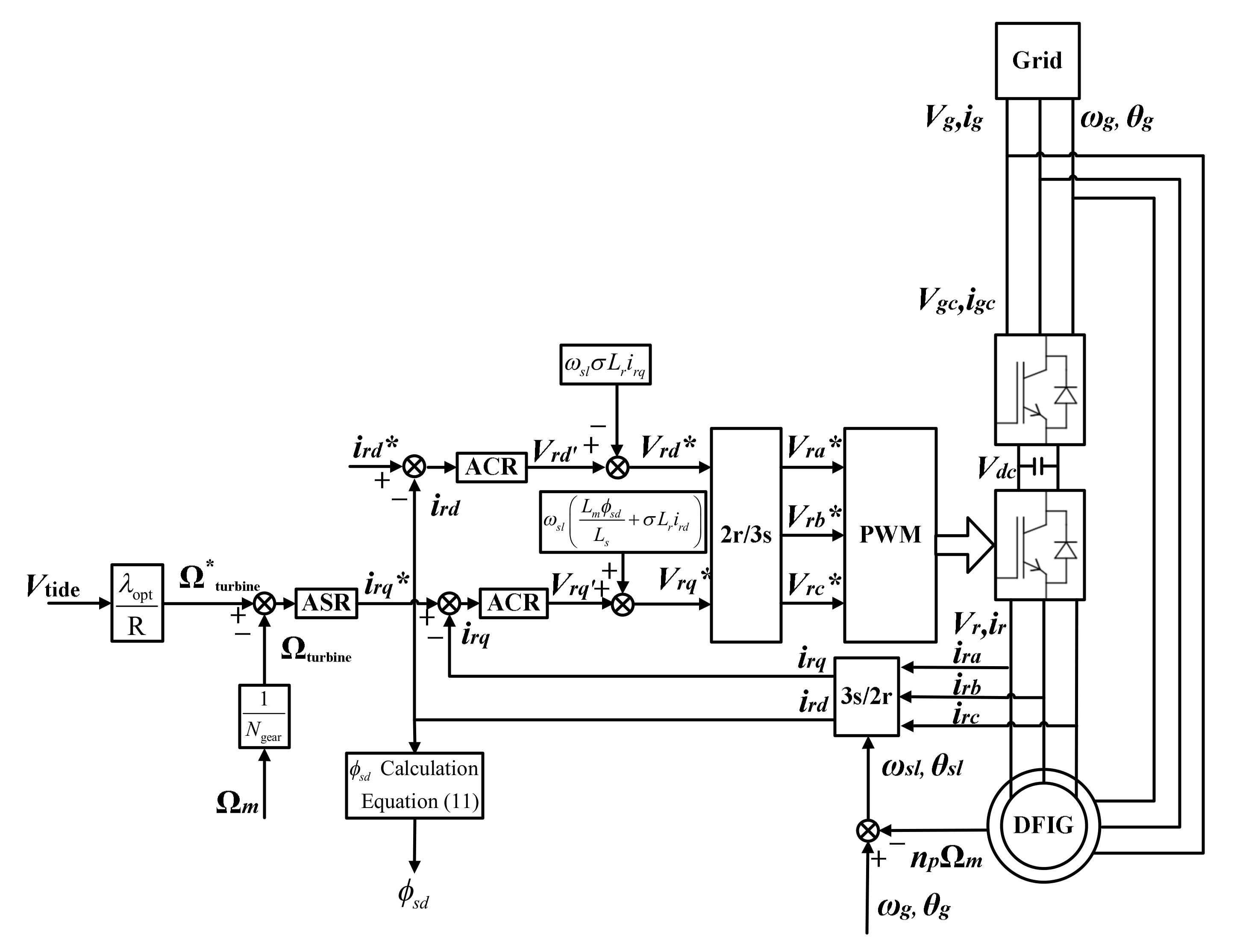
For this strategy, the turbine speed, which would extract the maximum power from the tidal current, is deduced by the optimal tip-speed ratio method. Subsequently, the rotor current reference irq* is achieved by ASR; the rotor current reference ird* can be obtained in (11) which is developed from the stator reactive power and stator flux equations. Then, RSC realizes the excitation control with the control signal of ACR. ASR and ACR can be either FOPI controller or IOPI controller. The processes to obtain the controllers are detailed in the following sections. The basic diagram of this control strategy is given in Figure 3.
i r d = L s L m ϕ s L s Q s 1.5 ω s ϕ s = L s L m V s ω s L s Q s 1.5 V s

3.2. Current Loop

Based on (8), the current open-loop transfer function is represented in (12).
G e , o p s = k p e + k i e s 1 σ L r s + R r = k p e σ L r s + k i e σ L r s s + R r σ L r
For IOPI controller of ACR, the parameters are determined by the pole placement method in this paper [64,65]. Thus, the relative closed-loop transfer function can be later simply developed in the following (13). When the time trends to zero, the first item of the molecule will be zero. Consequently, according to the automatic control theory, the settling time tse of this second-order system can be approximated in (14) for ±5% error bandwidth [39,64,66]. Then, the parameters kpe and kie are deduced in (15) subsequently [63].
G e , c l ( s ) = G e , o p 1 + G e , o p = k p e σ L r s + k i e σ L r s 2 + R r + k p e σ L r s + k i e σ L r ω n e 2 s 2 + 2 ξ ω n e s + ω n e 2
t s e = 3 ξ ω n e
k p e = 6 σ L r t s e R r k i e = 9 σ L r ξ 2 t s e 2

3.3. Speed Loop

The external speed loop aims to follow the optimal speed reference for the maximum power extraction from the tidal current flow. In this section, the current loop is considered as 1 for simplification. Based on the assumption, the relative speed open and closed loops transfer functions are presented in (16) and (17) separately. Then, the controller parameters of ASR could be developed by the same method as the current loop in (18).
G m , o p s = k p m + k i m s 1 J m s + f v = k p m J m s + k i m J m s s + f v J m
G m , c l ( s ) = k p m J m s + k i m J m s 2 + f v + k p m J m s + k i m J m ω n m 2 s 2 + 2 ξ ω n m s + ω n m 2
k p m = 6 J m t s m f v k i m = 9 J m ξ 2 t s m 2

4. Fractional-Order PI Controller

Although the fractional calculus is quite an ancient mathematical subject, it is usually applied to develop more practical and accurate models and to improve the traditional control algorithms right now. Consequently, the researchers regard it as one powerful and effective instrument for ameliorating engineering solutions [40].
Until now, many researchers have proposed various fixed structures for the fractional-order controller, such as: different generations of CRONE controller proposed by A. Oustaloup [67], TID controller [68], FOPID controller and the fractional-order lead-lag compensator [69,70]. According to the algorithms of the different generations of the CRONE controller, FOPID controller has a strong suppression effect on high-frequency and low-frequency disturbances; that is to say, the robustness of the fractional-order controller is much better than the traditional IOPID controller [71].

4.1. Basic Introduction of Fractional-Order PID Controller

FOPID controller is also known as the PIλDμ controller. For this controller, the fractional-order integrator 1/sλ and differentiator sμ replace the integer-order integrator 1/s and differentiator s of IOPID controller. Thus, the relative general form is simplified in (19). λ and μ are bounded between 0 and 2: 0 < λ < 2, 0 < μ < 2 [72,73].
C ( s ) = K p + K i s λ + K d s μ
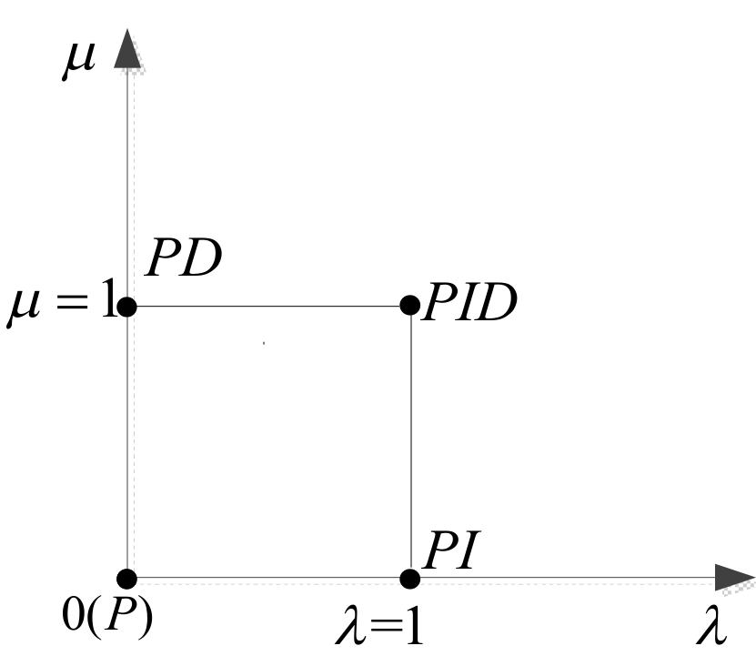
The relationship between the IOPID and FOPID controllers are presented in Figure 4. If λ = μ = 1, FOPID controller becomes IOPID controller. Therefore, FOPID controller can be considered as an exception of IOPID controller. When Kd = 0 or Ki = 0, FOPID controller turns to be FOPI or FOPD controller. As a result, they can simply be regarded as a subclass of FOPID controller and an extension of the traditional IOPI or IOPD controller.
From this figure, IOPID controller can only change the parameters at the four points; while for the FOPID controller, it can take the values in this quadrant. Because of these two adjustable parameters λ and μ, they can highly improve the performance and robustness of the whole system. However, it undoubtedly makes the process of parameter tuning more complex [69].
Theoretically, the fractional-order system is an infinite dimension system. The conventional analysis approach of the integer-order system cannot be applied directly. Therefore, some appropriate methods are proposed by the researchers to analyze the fractional-order systems. Right now, the discretization and approximation of the rational functions of the fractional-order systems becomes one of the main methods [74]. In this paper, the Oustaloup approximation method is selected to solve the fractional-order problem [75].

4.2. Design of FOPI Controller

There are many different parameter tuning algorithms for FOPID controller. At present, the mainly used methods include optimization method, dominant pole algorithm, phase-and-amplitude-margin method, etc. [45,63,76,77].
In this paper, phase-and-amplitude-margin method is applied to design this robust controller. For this method, the phase margin must be regarded as the most important criterion to obtain the relative stability of the system. If the gain crossover frequency ωc and the phase margin γc are determined, the controller parameters can be easily achieved according to the tuning rules. The parameter tuning process is detailed in the following steps [56,57,58,63,78,79].
(1)
Determination of the phase-frequency characteristics at ωc:
A r g G j ω c = A r g C j ω c P j ω c = π + γ c
(2)
Determination of the amplitude-frequency characteristics at ωc:
G j ω c dB = C j ω c P j ω c dB = 0 dB
(3)
Robustness to the variations of the system gain:
The robust stability condition must be added to ensure the robust characteristics of the system. Thus, the phase in the open-loop Bode diagram should be flat near the gain crossover frequency ωc. When the gain of the system increases or decreases by 20%, the phase-to-frequency derivative in Bode diagram is 0 dB at the gain crossover frequency ωc and the overshoot of the dynamic response almost remains the same. To obtain such good robustness characteristics, the transfer function of the open-loop must satisfy (22).
d A r g C j ω c P j ω c d ω ω = ω c = 0
Usually, the unified FOPI controller is simply described as (23). Then, the relative frequency response can be developed in the following (24).
C ( s ) = K p 1 + K i s λ
C ( j ω ) = K p 1 + K i ω λ cos λ π 2 j K i ω λ sin λ π 2
According to the transfer functions in (12) and (16), they can be all approximated as a first-order system. The standard transfer function is given in (25).
P s = K T s + 1
where: T = σLr/Rr for the current loop and T = Jm/fv for the speed loop.
Subsequently, the standard form of the system could be rewritten in (26) and the open-loop transfer function is presented in (27).
P s = 1 T s + 1
G ( s ) = C s P s = K p 1 + K i s λ 1 T s + 1
According to the expressions in (25) to (27), the tuning rules in (20) to (22) could be rearranged in (28) to (30).
A r g [ G ( j ω c ) ] = arctan K i ω c λ sin λ π 2 1 + K i ω c λ cos λ π 2 arctan ω c T = π + γ c
G ( j ω c ) = C ( j ω c ) P ( j ω c ) = K p 1 + K i ω c λ cos λ π 2 2 + K i ω c λ sin λ π 2 2 1 + ( ω c T ) 2 = 1
d A r g G j ω d ω ω = ω c = K i λ ω c λ 1 sin λ π 2 ω c 2 λ + 2 K i ω c λ cos λ π 2 + K i 2 T 1 + ( T ω c ) 2 = 0
For this method, the phase margin γc and the gain crossover frequency ωc are required. For the sake of comparing the performance between two controllers, FOPI controller would choose the same phase margin and gain crossover frequency as IOPI controller.
Based on the open-loop transfer functions with IOPI controller for the current and speed loops in (12) and (16), the relative frequency characteristics could be achieved in (31) and (32) subsequently.
G e , o p j ω = k p e σ L r j ω + ω 2 j ω j ω + R r σ L r ,
G m , o p j ω = k p m J m j ω + ω 2 j ω j ω + f v J m ,
According to the phase-frequency characteristic at the gain crossover frequency ωc, the amplitude-margins of the current and speed loops must be 0 dB: |Ge,op(ce)| = 1 & |Gm,op(cm)| = 1. Consequently, the frequencies (ωce and ωcm) and the relative phases [φ(ωce) and φ(ωcm)] can be obtained by (33) to (36) respectively. Then, the phase margins (γce and γcm) are developed in (37) and (38) consequently.
ω c e = R r 2 σ 2 L r 2 k p e 2 σ 2 L r 2 + R r 2 σ 2 L r 2 k p e 2 σ 2 L r 2 2 + 4 ω n e 4 2
ω c m = f v 2 J m 2 k p m 2 J m 2 + f v 2 J m 2 k p m 2 J m 2 2 + 4 ω n m 4 2
φ ω c e = arctan k p e ω c e σ L r ω n e 2 π 2 arctan σ L r ω c e R r
φ ω c m = arctan k p m ω c m J m ω n m 2 π 2 arctan J m ω c m f v
γ c e = π + φ ω c e = π 2 + arctan k p e ω c e σ L r ω n e 2 arctan σ L r ω c e R r
γ c m = π + φ ω c m = π 2 + arctan k p m ω c m J m ω n m 2 arctan J m ω c m f v
If the damping ratio ξ for these two loops equates to 0.707, the settling times of the current and speed loops are 0.001 s and 3 s respectively, consequently, the relative gain crossover frequencies are ωce = 6536 rad/s and ωcm = 2.18 rad/s, the phase margins for the two loops are γcm = γce ≈ 1.147 rad. In order to get the fractional-order coefficient, equations (28) and (30) must be combined as a set of simultaneous equations. Then, the coefficients λ and Ki can be calculated. Finally, the coefficient Kp can be achieved by (29). According to this solving process, the FOPI controllers of the two loops (Gfopim and Gfopie) can be designed in (39) and (40). Subsequently, the open-loop transfer functions could be future developed with the Oustaloup approximation algorithm. The corresponding Bode diagrams of the current and speed open-loops are shown in Figure 5. From these figures, the phases of the two systems near each gain crossover frequency ωc are almost the same (equal to −π+γc). It means that these two FOPI controllers are well designed and they all have strong gain robustness characteristics.
G f o p i e s = 10.4952 1 + 86.1313 s 0 . 3372
G f o p i m s = 0 . 0535 1 + 14 . 94 s 0 . 299

5. Simulation and Comparison

To verify the proposed control method, the simulation is accomplished by MATLAB/SIMULINK in this part. The performance of the two controllers is analyzed and compared subsequently.
In this section, the settling time tse of the current loop IOPI controller is fixed as 1 ms. Then, the parameters of FOPI controller are designed according to the relative phase margin γce and crossover frequency ωce of IOPI controller.

5.1. Comparison of the Two Controllers

This part will analyze the performance with the different settling times tsm of the speed loop. According to the tuning method detailed above, the relative parameters of FOPI controller could be obtained with the gain crossover frequency and phase margin of every settling time. Consequently, the performance with IOPI and FOPI controllers for the different speed settling times tsm is presented in Figure 6. All the black lines indicate the response of FOPI controller; meanwhile, the red lines imply that of IOPI controller. The different styles of lines (solid line, dashed line, dotted line, and dash-dot line) represent the different settling times.
From Figure 6a, with the different tsm, FOPI and IOPI controllers can follow the reference in the given time. However, for each condition, FOPI controller always appears much quicker response compared with IOPI controller. Moreover, the overshoots of FOPI controller are much smaller than that of IOPI controller for each tsm. In addition, the overshoot of FOPI controller will decrease with the increasing settling time from this figure.
Figure 6b,c shows the electromagnetic torques and rotor current amplitudes of two controllers with different tsm. As the tidal current speeds are the same for these two systems, the final electromagnetic torques and rotor current amplitudes must be the same respectively. However, due to the different speed responses, the torque and current amplitude of IOPI controller will have bigger oscillations and reach their desired values in a longer time. What should be mentioned is that there is a shock in the current at the starting stage for both two controllers, while there is a shock in the torque only for IOPI controller. Indeed, this torque shock can be weakened by the increasing settling time. Nevertheless, the FOPI controller always presents smoother starting performance compared with the IOPI controller. As TST may have big rotor inertia and the inertia may increase due to the adhesion of marine fouling organisms, this characteristic can greatly avoid some mechanical faults that may occur during system start-up [80,81,82].
Due to the better performance of the speed and current FOPI controllers, the corresponding active power is presented in Figure 6d. From this figure, FOPI controller is always much faster than IOPI controller to reach the maximum active power.

5.2. Robustness Analysis

In this section, the robustness of the speed loop is analyzed. For the speed loop, the mechanical equation contains two parameters: rotor inertia Jm and viscosity coefficient fv and can be considered as one low-pass filter after Laplace transformation. In order to simplify the analysis, the rotor inertia and viscosity coefficient would have the same variation.
In this part, the settling time tsm is fixed at 3 s. Then, the performance comparisons are presented in the following figures. The annotations in these figures imply the different rotor inertia and viscosity coefficient compared with the initial values.
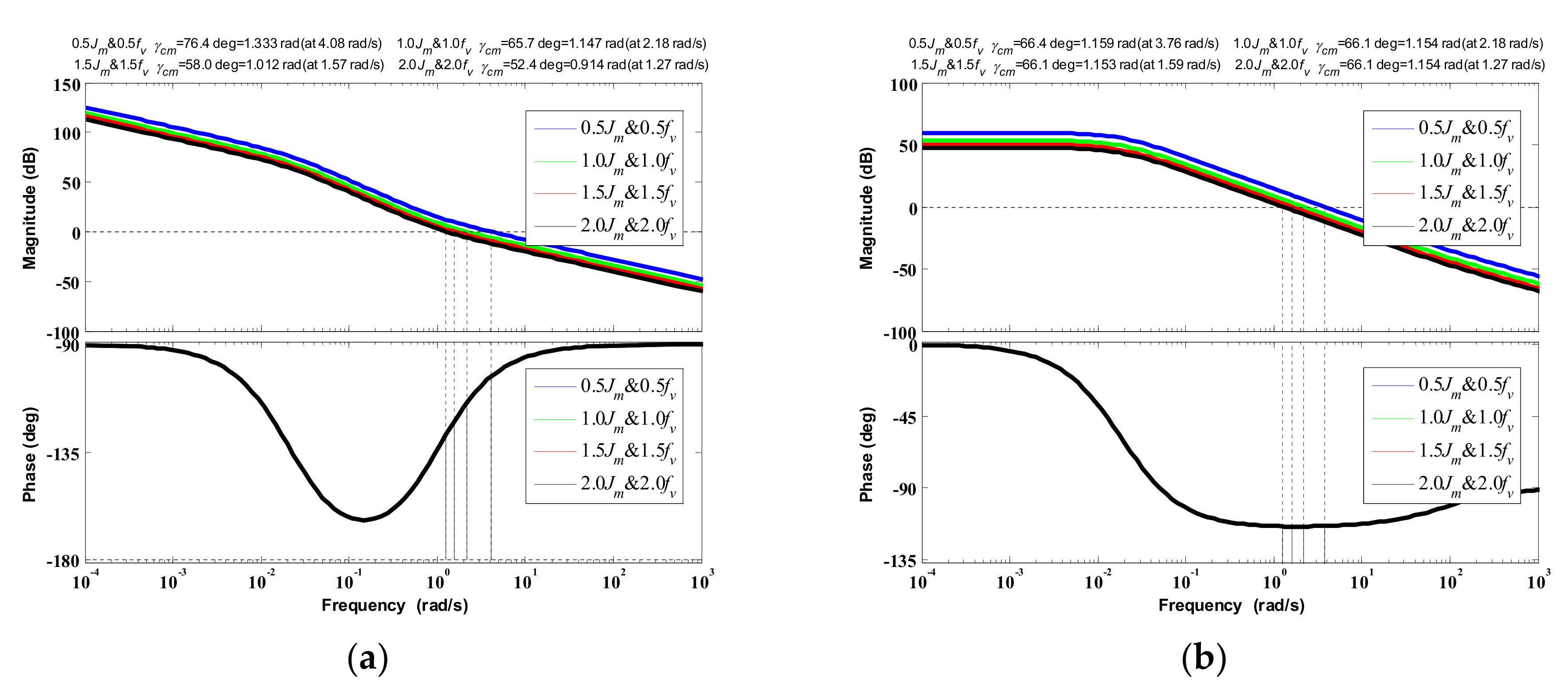
Firstly, bode diagrams of the two systems with different rotor inertia and viscosity coefficient are given in Figure 7. Apparently, if the system parameters vary, the phase-and-amplitude-margin characteristics must change. Although the system gain crossover frequencies will all change with these new modified system models and the same controllers, the FOPI controller can almost keep the same phase margin as the original case. It implies that it can maintain the system stability under these conditions. While for IOPI controller, the stability will be changed with these different system parameters.
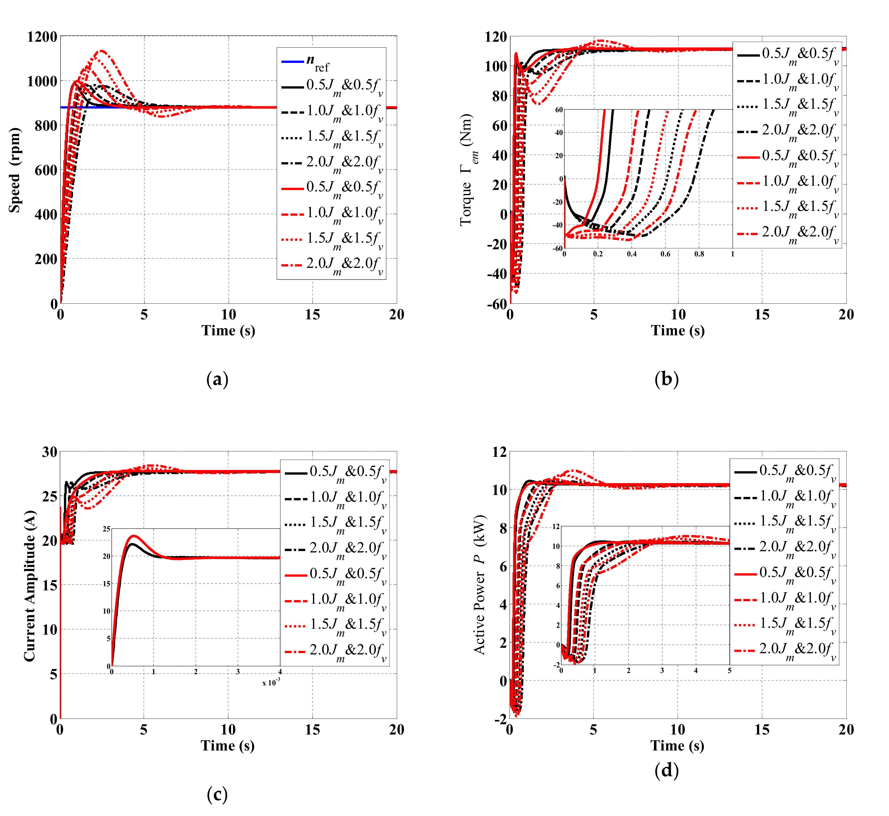
The speed responses of the two controllers are shown in Figure 8a. Absolutely, the speed performance of the two systems varies with the different rotor inertia Jm and viscosity coefficient fv. In general, the speed rising times of the two controllers will all rise with the increasing Jm and fv. The difference is that the rising times of FOPI controller are always relative smaller than that of IOPI controller. Significantly, the speed overshoots of the FOPI controller will remain almost the same. This phenomenon just verifies the robustness to the variations of the system gain which has already been mentioned in the tuning process. For the IOPI controller, its overshoot will grow with the increasing rotor inertia and viscosity coefficient.
Figure 8b,c indicates the electromagnetic torque and rotor current amplitude. From these two figures, there is always a shock for IOPI controller at the beginning. Meanwhile, its oscillations will be bigger with the bigger rotor inertia Jm and viscosity coefficient fv. While for the active power in Figure 8d, these two controllers have similar performance during the start-up. However, the IOPI controller will bring a slight fluctuation. Its value will increase with the raising Jm and fv, and can reach nearly 10% when Jm and fv are twice the original values.
Consequently, from these figures, the FOPI controller can ensure the robustness to parameter variations and system uncertainties. All the simulation results also demonstrate that the FOPI controller always appears much better performance compared with the IOPI controller under these conditions.

5.3. Performance Analysis with the Tidal Current Variation

The marine tidal current speed could be regarded as constant in a short time. However, because of the turbulence and swell effects, the speed is always changing. In this part, the performance analysis and comparison of two controllers will be presented considering varying tidal current speeds.
Firstly, the tidal current speed is considered to have step changes. In the simulation, the marine tidal current speed is 1.8 m/s at the beginning, rises to 2 m/s at 20 s, and then decreases to 1.5 m/s at 40 s. As the two systems are analyzed based on the same condition and parameters, the final values of the rotor current amplitude, torque, and active power must be the same. The relative mechanical speeds with the two controllers are shown in Figure 9a. According to this figure, the overshoot of the FOPI controller is always much smaller than that of the IOPI controller. From Figure 9b–d, when the marine tidal current speed changes suddenly, the torque, current amplitude, and active power will be different in the transient process due to the different responses of the controllers. Moreover, the relative oscillations and the current overshoot will be a little smaller if FOPI controller is employed.
Secondly, the swell effect is applied to simulate the continual variable speed. Indeed, the swell effect is the most important perturbation to vary the flow speed [19]. According to the literature, the simple first-order Stokes model is selected and shown in (41). In order to get this swell effect, some parameters must be obtained beforehand. In this section, the JONSWAP spectrum is adopted because of its sharp peak characteristic which is given in (42). Then, the amplitude of each frequency component ai can be calculated in (43). The other important parameter, each swell length Li, can be achieved by the sea wave dispersion relation in (44) [7,8,19]. If the average marine current is 2 m/s, the total speed including the swell effect is shown in Figure 10 as an example. As can be seen from this figure, if the swell effect is considered, the marine tidal current speed will vary within a certain range continuously.
V swell t = i 2 π a i T i cosh 2 π z + d e p t h L i sinh 2 π d e p t h L i cos 2 π t T i x L i + φ i
S f = k J g 2 2 π 4 f 5 exp 5 4 f m f 4 γ α
a i = 2 S f i Δ f
L i = g T i 2 2 π tanh 2 π d e p t h L i
where:
  • γ = 3.3
  • k J = 0.076 x 0.22 = 0.076 g L F V wind 2 0.22
  • α = exp f f m 2 2 σ 2 f m 2   with   σ = 0.07 f f m 0.09 f   >   f m
  • f m = 3.5 g L F V wind 2 0.33
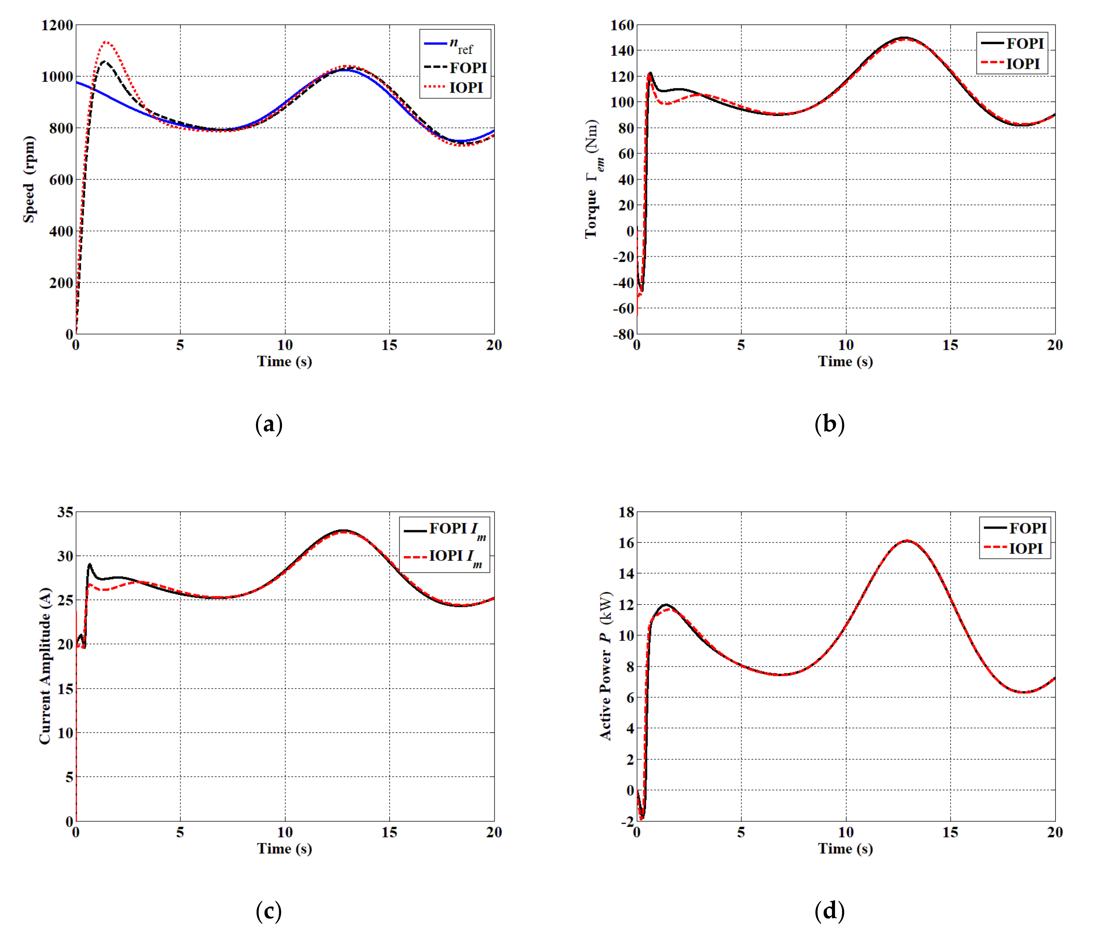
In this part, the system will be simulated only 20 s for simplification. The mechanical settling time is also equal to 3 s as before. The system performance is presented in Figure 11. If the marine current speed varies continuously, both FOPI and IOPI controllers cannot track the speed reference perfectly due to the limitation of PI controller and always have a static error. However, FOPI controller has better starting characteristics compared to IOPI controller in the speed (see in Figure 11). For the torque, current amplitude and active power, two controllers have similar response characteristics except for the start-up process. IOPI controller will have a little bigger fluctuation during the transient process.
Overall, all the analysis in this section only demonstrates the good starting performance of FOPI controller with the variable tidal speed. Nevertheless, it cannot prove its good characteristics during the steady-state process. Furthermore, the IOPI controller seems to have a bigger step pulse when the reference changes suddenly. Considering the possible strong current speed variations/disturbances, it is very important to ensure the TST to have smoother reactions. From this point of view, FOPI controller’s low overshoot characteristic can be advantageous in TST applications.
It should also be noted that all the research in this section is based on the precise model of the system and a shorter settling time. According to the analysis in the previous two sections, the FOPI controller has already demonstrated its prominent advantage in the aspects of different settling time and robustness. Therefore, it is reasonable to believe that if the system model is inaccurate and the marine tidal current has a big variation, the FOPI controller must have better performance compared to the IOPI controller.

6. Conclusions

This paper compares the conventional IOPI and proposed FOPI controllers in a DFIG-based TST. The obtained simulation results are very interesting. They show that the FOPI controller can obtain desired results and present better performance than IOPI controller in the FOC control strategy. (1) The FOPI controller will get smaller overshoot and static error, less adjustment time, and better robustness with variable marine current speed and uncertain system parameters. (2) The FOPI controller can significantly improve the start-up performance and make the system into steady-state without a big impact.
From the system simulation, the FOPI controller demonstrates high effectiveness in terms of speed tracking and current regulation. It implies that the FOPI controller could be a very good candidate in TST applications for the normal operation condition even the system model is inaccurate due to the complex working environment. In the future, a system in faulty condition using a FOPI controller will be studied because of its prominent advantage in the overshoot and robustness.

Author Contributions

Conceptualization, H.C., W.X., J.H. and T.T.; methodology, H.C. and X.C.; software, X.C. and H.C.; validation, X.C. and H.C.; formal analysis, H.C. and X.C.; investigation, X.C.; resources, M.B. and N.A.-A.; data curation, X.C.; writing—original draft preparation, X.C. and H.C.; writing—review and editing, H.C., Z.Z., N.A.-A. and M.B.; visualization, M.B., W.X. and J.H.; supervision, T.T., M.B. and H.C.; project administration, H.C. and M.B.; funding acquisition, H.C. All authors have read and agreed to the published version of the manuscript.

Funding

This research was funded by National Natural Science Foundation of China and Natural Science Foundation of Shanghai, China, grant number 61503242, 61673260 and 15ZR1419800.

Acknowledgments

The authors acknowledge the Research Institute of Power Drive and Control of Shanghai Maritime University, Institut de Recherche en Energie Electrique de Nantes Atlantique of University of Nantes and UMR CNRS 6027 IRDL of University of Brest.

Conflicts of Interest

The authors declare no conflict of interest.

Nomenclature

TSTTidal Stream Turbine
WECSWind Energy Conversion System
IOPIInteger-Order PI
FOPIFractional-Order PI
TSRTip Speed Ratio/λ
PMSGPermanent Magnet Synchronous Generator
DFIGDoubly-Fed Induction Generator
DSPMDoubly Salient Permanent Magnet machine
SMCSliding Mode Control
HOSMCHigh-Order Slide Mode Control
MPCModel Predictive Control
NPCNonlinear Predictive Control
ADRCActive Disturbance Rejection Control
ITAEIntegral of Time multiplied by Absolute Error
PSOParticle Swarm Optimization
ITSEIntegral of the Time multiplied Square Error
BFOBacterial Foraging Optimization
ASRAutomatic Speed Regulator
RSCRotor-Side Converter
ACRAutomatic Current Regulator
CRONECommande Robuste d’Ordre Non Entier
TIDTilt-Integral Derivative
FOPIDFractional-Order PID
ρSeawater density (1024 kg/m3)
CpPower coefficient, also called Betz’s coefficient
λTip Speed Ratio (TSR)
Ωturbine, ΩmMechanical speed of the turbine/DFIG (rad/s)
a, bAxial and tangential flow induction factors
dFN, dFTAxial and tangential components of the blade element hydrodynamic forces (N)
ϕAngle of the resultant velocity “W” relative to the rotor plane (rad)
R, RRadius of the turbine (m), the resistance (Ω)
NbNumber of the blades
s, rStator/rotor index
d, qSynchronous reference frame index
V, i, φ, ωVoltage (V), current (A), flux (Wb) and electrical speed (rad/s)
slSlip
ωslRotor current speed (rad/s)
Ls, Lr, LmSelf inductances of the stator and rotor, and mutual inductances (H, H, H)
ΓemElectromagnetic torque (Nm)
npNumber of the pole pair
JmInertia (kg*m2)
fvViscosity coefficient
Ps, QsStator active and reactive powers (W, VAR)
NgearRatio of the gearbox
VsVoltage amplitude (V)
ξDamping ratio
e, melectrical/mechanical index
tsSettling time of the closed-loop (s)
kp, kiProportional and integral coefficients
ωc, γcGain crossover frequency and the phase margin for the open-loop (rad/s, rad)
Kp, Ki, KdProportional, integral and differential constants
λ and μIntegral and differential orders
KAmplification coefficient which can be integrated into the proportional coefficient Kp
TTime constant
γPeak enhancement factor which indicates the ratio of the maximal spectral energy to the maximum of the corresponding Pierson-Moskowitz spectrum
LFFetch length (m)
VwindWind speed (m/s)
gAcceleration of gravity (m/s2)
f, fmWave frequency and the frequency at the maximum of the spectrum (Hz, Hz)
kJUsual Phillips constant
TiSwell period of each component (s)
φiInitial phase of each term which is given randomly (rad)
depthSea depth (m)
x, zHorizontal and vertical point for the calculation (m)

References

  1. Chen, H.; Tang, T.H.; Aït-Ahmed, N.; Benbouzid, M.; Machmoum, M.; Zaïm, M.E.H. Attraction, challenge and current status of marine current energy. IEEE Access 2018, 6, 12665–12685. [Google Scholar] [CrossRef]
  2. Zhou, Z.; Benbouzid, M.; Charpentier, J.F.; Scuiller, F.; Tang, T. Developments in large marine current turbine technologies—A review. Renew. Sustain. Energy Rev. 2017, 77, 852–858. [Google Scholar] [CrossRef]
  3. Touimi, K.; Benbouzid, M.; Tavner, P. Tidal stream turbines: With or without a gearbox? Ocean Eng. 2018, 170, 74–88. [Google Scholar] [CrossRef]
  4. Ang, K.H.; Chong, G.; Li, Y. PID control system analysis, design, and technology. IEEE Trans. Control Syst. Technol. 2005, 13, 559–576. [Google Scholar]
  5. Zhou, Z.; Scuiller, F.; Charpentier, J.F.; Benbouzid, M.; Tang, T. Power control of a nonpitchable PMSG-based marine current turbine at overrated current speed with flux-weakening strategy. IEEE J. Ocean. Eng. 2015, 40, 536–545. [Google Scholar] [CrossRef] [Green Version]
  6. Anwar, M.B.; Moursi, M.S.E.; Xiao, W. Dispatching and frequency control strategies for marine current turbines based on doubly fed induction generator. IEEE Trans. Sustain. Energy 2015, 7, 262–270. [Google Scholar] [CrossRef]
  7. Zhou, Z.; Scuiller, F.; Charpentier, J.F.; Benbouzid, M.; Tang, T. Power Limitation Control for a PMSG-Based Marine Current Turbine at High Tidal Speed and Strong Sea State. In Proceedings of the 2013 International Electric Machines & Drives Conference (IEEE IEMDC′13), Chicago, IL, USA, 12–15 May 2013; pp. 75–80. [Google Scholar]
  8. Zhou, Z.; Scuiller, F.; Charpentier, J.F.; Benbouzid, M.; Tang, T. Grid-Connected Marine Current Generation System Power Smoothing Control Using Supercapacitors. In Proceedings of the IECON 2012, 38th Annual Conference on IEEE Industrial Electronics Society, Montreal, QC, Canada, 25–28 October 2012; pp. 4035–4040. [Google Scholar]
  9. Greco, L.; Testa, C.; Cirrincione, M.; Pucci, M.; Vitale, G. Effectiveness of a GNG-based MPPT and related control system for marine current turbines in unsteady operating conditions. In Proceedings of the 2015 IEEE Energy Conversion Congress and Exposition (ECCE2015), Montreal, QC, Canada, 20–24 September 2015; pp. 1027–1034. [Google Scholar]
  10. Anwar, B.; Moursi, M.S.E.; Xiao, W. A Novel Frequency Control Strategy for Large Scale Marine Current Turbines Based on Doubly Fed Induction Generator. In Proceedings of the 3rd Renewable Power Generation Conference (RPG 2014), Naples, Italy, 24–25 September 2014; pp. 1–6. [Google Scholar]
  11. Pucci, M.; Cirrincione, M.; Greco, L.; Testa, C.; Vitale, G. Marine current turbine generator system with induction machine growing neural gas (GNG) MPPT based on sensorless sea speed estimation. In Proceedings of the 2015 IEEE Energy Conversion Congress and Exposition (ECCE2015), Montreal, QC, Canada, 20–24 September 2015; pp. 3901–3908. [Google Scholar]
  12. Ghefiri, K.; Bouallègue, S.; Haggège, J.; Ghefiri, K.; Garrido, I.; Garrido, A.J. Modeling and MPPT control of a Tidal stream generator. In Proceedings of the 2017 4th International Conference on Control, Decision and Information Technologies (CoDIT), Barcelona, Spain, 5–7 April 2017; pp. 1003–1008. [Google Scholar]
  13. Fall, O.; Charpentier, J.F.; Nguyen, N.K.; Letellier, P. Maximum Torque Per Ampere Control Strategy of a 5-phase PM Generator in healthy and faulty modes for tidal marine turbine application. In Proceedings of the 2014 International Power Electronics and Application Conference and Exposition (PEAC), Shanghai, China, 5–8 November 2014; pp. 468–473. [Google Scholar]
  14. Mademlis, G.; Liu, Y.; Chen, P.; Singhroy, E. Generator Speed Control and Experimental Verification of Tidal Undersea Kite Systems. In Proceedings of the 2018 XIII International Conference on Electrical Machines (ICEM), Alexandroupoli, Greece, 3–6 September 2018; pp. 1531–1537. [Google Scholar]
  15. Jahromi, M.J.; Maswood, A.I.; Tseng, K.J. Design and evaluation of a new converter control strategy for near-shore tidal turbines. IEEE Trans. Ind. Electron. 2013, 60, 5648–5659. [Google Scholar] [CrossRef]
  16. Toumi, S.; Benelghali, S.; Trabelsi, M.; Elbouchikhi, E.; Momouni, M.F. Robustness Analysis and Evaluation of a PMSG-based Marine Current Turbine System under Faulty Conditions. In Proceedings of the 2014 15th International Conference on Sciences and Techniques of Automatic Control and Computer Engineering (STA), Hammamet, Tunisia, 21–23 December 2014; pp. 631–636. [Google Scholar]
  17. Barakat, M.R.; Tala-Ighil, B.; Chaoui, H.; Gualous, H.; Slamani, Y.; Hissel, D. Energetic Macroscopic Representation of a Marine Current Turbine System with Loss Minimization Control. IEEE Trans. Sustain. Energy 2018, 9, 106–117. [Google Scholar] [CrossRef]
  18. BenElghali, S.E.; Benbouzid, M.; Charpentier, J.F. Modeling and control of a marine current turbine driven doubly-fed induction generator. IET Renew. Power Gener. 2010, 4, 1–11. [Google Scholar] [CrossRef] [Green Version]
  19. Zhou, Z.; Scuiller, F.; Charpentier, J.F.; Benbouzid, M.; Tang, T. Power Smoothing Control in a Grid-Connected Marine Current Turbine System for Compensating Swell Effect. IEEE Trans. Sustain. Energy 2013, 4, 816–826. [Google Scholar] [CrossRef] [Green Version]
  20. BenElghali, S.E.; Benbouzid, M.; Charpentier, J.F.; Ahmed-Ali, T.; Munteanu, I. Experimental Validation of a Marine Current Turbine Simulator: Application to a Permanent Magnet Synchronous Generator-Based System Second-Order Sliding Mode Control. IEEE Trans. Ind. Electron. 2011, 58, 118–126. [Google Scholar] [CrossRef] [Green Version]
  21. BenElghali, S.E.; Benbouzid, M.; Ahmed-Ali, T.; Charpentier, J.F. High-Order Sliding Mode Control of a Marine Current Turbine Driven Doubly-Fed Induction Generator. IEEE J. Ocean. Eng. 2010, 35, 402–411. [Google Scholar] [CrossRef] [Green Version]
  22. Mekri, F.; BenElghali, S.E.; Benbouzid, M. Fault-tolerant control performance comparison of three- and five-phase pmsg for marine current turbine applications. IEEE Trans. Sustain. Energy 2013, 4, 425–433. [Google Scholar] [CrossRef]
  23. BenElghali, S.E.; Mekri, F.; Benbouzid, M.; Charpentier, J.F. Performance Comparison of Three- and Five-Phase Permanent Magnet Generators for Marine Current Turbine Applications Under Open-Circuit Faults. In Proceedings of the 2011 International Conference on Power Engineering, Energy and Electrical Drives, Malaga, Spain, 11–13 May 2011; pp. 1–6. [Google Scholar]
  24. Chen, H.; Tang, S.F.; Han, J.G.; Aït-Ahmed, N.; Tang, T. Second-Order Sliding Mode Current Control of Doubly Salient Permanent Magnet Generator. In Proceedings of the IECON 2019, 45th Annual Conference of the IEEE Industrial Electronics Society, Lisbon, Portugal, 14–17 October 2019; pp. 7010–7015. [Google Scholar]
  25. Mohd Zaihidee, F.; Mekhilef, S.; Mubin, M. Robust Speed Control of PMSM Using Sliding Mode Control (SMC)—A Review. Energies 2019, 12, 1669. [Google Scholar] [CrossRef] [Green Version]
  26. Gu, Y.J.; Yin, X.X.; Liu, H.W.; Li, W.; Lin, Y.G. Fuzzy terminal sliding mode control for extracting maximum marine current energy. Energy 2015, 90, 258–265. [Google Scholar] [CrossRef]
  27. Pham, H.T.; Bourgeot, J.M.; Benbouzid, M. Fault-tolerant finite control set-model predictive control for marine current turbine applications. IET Renew. Power Gener. 2018, 12, 415–421. [Google Scholar] [CrossRef]
  28. Toumi, S.; Amirat, Y.; Trabelsi, M.; Elbouchikhi, E.; Mimouni, M.F.; Benbouzid, M. Backstepping control of a PMSG-based marine current turbine system under faulty conditions. In Proceedings of the 2018 9th International Renewable Energy Congress (IREC), Hammamet, Tunisia, 20–22 March 2018; pp. 1–6. [Google Scholar]
  29. Yin, X.; Zhao, X. ADV Preview Based Nonlinear Predictive Control for Maximizing Power Generation of a Tidal Turbine with Hydrostatic Transmission. IEEE Trans. Energy Conv. 2019, 34, 1781–1791. [Google Scholar] [CrossRef]
  30. Yin, X.X.; Zhang, W.C.; Jiang, Z.S.; Pan, L.; Lei, M.Z. Adaptive backstepping control for maximizing marine current power generation based on uncertainty and disturbance estimation. Int. J. Electr. Power Energy Syst. 2020, 117, 1–11. [Google Scholar] [CrossRef]
  31. Khan, N.; Rabbi, S.F.; Hinchey, M.J.; Rahman, M.A. An adaptive nonlinear MPPT controller for stand alone marine current energy conversion systems. In Proceedings of the IECON 2013, 39th Annual Conference of the IEEE Industrial Electronics Society, Vienna, Austria, 10–13 November 2013; pp. 406–411. [Google Scholar]
  32. Khan, N.; Rabbi, S.F.; Hinchey, M.J.; Rahman, M.A. Adaptive backstepping based maximum power point tracking control for a variable speed marine current energy conversion system. In Proceedings of the 26th IEEE Canadian Conference on Electrical and Computer Engineering (CCECE), Regina, SK, Canada, 5–8 May 2013; pp. 1–5. [Google Scholar]
  33. Choi, J.S.; Jeong, R.G.; Shin, J.H.; Kim, C.K.; Kim, Y.S. New control method of maximum power point tracking for tidal energy generation system. In Proceedings of the 2007 International Conference on Electrical Machines and Systems (ICEMS), Seoul, Korea, 8–11 October 2007; pp. 165–168. [Google Scholar]
  34. Ghefiri, K.; Garrido, I.; Garrido, A.J.; Bouallègue, S.; Haggège, J. Fuzzy Gain Scheduling of a Rotational Speed Control for a Tidal Stream Generator. In Proceedings of the 2018 International Symposium on Power Electronics, Electrical Drives, Automation and Motion (SPEEDAM), Amalfi, Italy, 20–22 June 2018; pp. 1271–1277. [Google Scholar]
  35. Zhou, Z.; BenElghali, S.E.; Benbouzid, M.; Amirat, Y.; Elbouchikhi, E.; Feld, G. Control Strategies for Tidal Stream Turbine Systems-A Comparative Study of ADRC, PI, and High-Order Sliding Mode Controls. In Proceedings of the IECON 2019, 45th Annual Conference of the IEEE Industrial Electronics Society, Lisbon, Portugal, 14–17 October 2019; pp. 6981–6986. [Google Scholar]
  36. Zhou, X.; Wang, T.; Zhang, M.; Xie, T.; Li, Z.; Pandey, S. A Control Strategy for Active Disturbance Rejection Control Based on Marine Current Turbine. In Proceedings of the IECON 2019, 45th Annual Conference of the IEEE Industrial Electronics Society, Lisbon, Portugal, 14–17 October 2019; pp. 6975–6980. [Google Scholar]
  37. Zhou, Z.; BenElghali, S.E.; Benbouzid, M.; Amirat, Y.; Elbouchikhi, E.; Feld, G. Tidal stream turbine control: An active disturbance rejection control approach. Ocean Eng. 2020, 202, 107190. [Google Scholar] [CrossRef]
  38. Monje, C.A.; Chen, Y.; Vinagre, B.M.; Xue, D.; Feliu-Batlle, V. Fractional-Order Systems and Controls Fundamentals and Applications; Springer: Berlin/Heidelberg, Germany, 2010; pp. 251–256. [Google Scholar]
  39. Kumar, D.M.; Mudaliar, H.K.; Cirrincione, M.; Mehta, U.; Pucci, M. Design of a Fractional Order PI (FOPI) for the Speed Control of a High-Performance Electrical Drive with an Induction Motor. In Proceedings of the 2018 21st International Conference on Electrical Machines and Systems (ICEMS), Jeju, Korea, 7–10 October 2018; pp. 1198–1202. [Google Scholar]
  40. Tavazoei, M.S. From Traditional to Fractional PI Control: A Key for Generalization. IEEE Ind. Electron. Mag. 2012, 6, 41–51. [Google Scholar] [CrossRef]
  41. Hammami, R.; Ameur, I.B.; Jelassi, K. Performance evaluation of fractional order controller for induction machine control and comparative study between FOC PI & FOC FOPI. In Proceedings of the 2017 18th International Conference on Sciences and Techniques of Automatic Control and Computer Engineering (STA), Monastir, Tunisia, 21–23 December 2017; pp. 272–277. [Google Scholar]
  42. Yu, W.; Chen, Y.Q.; Luo, Y.; Pi, Y.G. Frequency domain modelling and control of fractional-order system for permanent magnet synchronous motor velocity servo system. IET Contr. Theory Appl. 2016, 10, 136–143. [Google Scholar] [CrossRef] [Green Version]
  43. Torvik, P.J.; Bagley, R.L. On the appearance of the fractional derivative in the behaviour of real material. J. Appl. Mech. Trans. ASME 1984, 51, 294–298. [Google Scholar] [CrossRef]
  44. Luo, Y.; Li, H.S.; Chen, Y.Q. Fractional order proportional and derivative controller synthesis for a class of fractional order systems: Tuning rule and hardware-in-the-loop experiment. In Proceedings of the 48th IEEE Conference on Decision and Control (CDC) held jointly with 2009 28th Chinese Control Conference, Shanghai, China, 14–18 December 2009; pp. 5406–5465. [Google Scholar]
  45. Luo, Y.; Chen, Y.Q.; Wang, C.Y.; Pi, Y.G. Tuning fractional order proportional integral controllers for fractional order systems. J. Process Control 2010, 20, 823–831. [Google Scholar] [CrossRef]
  46. Hammami, R.; Ameur, I.B.; Jelassi, K. Induction machine: Fractional order proportional integral speed control. In Proceedings of the 2016 17th International Conference on Sciences and Techniques of Automatic Control and Computer Engineering (STA), Sousse, Tunisia, 19–21 December 2016; pp. 276–288. [Google Scholar]
  47. Li, C.; Chen, M.; Gao, S. Fractional order PI speed control for permanent magnet synchronous motor drives. In Proceedings of the 11th World Congress on Intelligent Control and Automation, Shenyang, China, 29 June–4 July 2014; pp. 4681–4685. [Google Scholar]
  48. Wang, D.; Song, B.; Kang, C.; Xu, J. Design of Fractional Order PI Controller for Permanent Magnet Synchronous Motor. In Proceedings of the 2018 2nd IEEE Advanced Information Management, Communicates, Electronic and Automation Control Conference (IMCEC 2018), Xi’an, China, 25–27 May 2018; pp. 780–784. [Google Scholar]
  49. Wang, R.; Pi, Y. Fractional-order PI speed control for permanent magnet synchronous motor. In Proceedings of the 2012 IEEE International Conference on Mechatronics and Automation, Chengdu, China, 5–8 August 2012; pp. 2303–2308. [Google Scholar]
  50. Wang, X.; Jiang, S.; Pan, Z.; Hoang, T.T.G.; Tian, L. Fractional-order Identification and Control of Permanent Magnet AC Servo System. In Proceedings of the 2019 Chinese Control Conference (CCC), Guangzhou, China, 27–30 July 2019; pp. 3108–3113. [Google Scholar]
  51. Evangeline, S.J.; Venmathi, K.; Ajayan, S. Speed control of switched reluctance motor using fractional order control. In Proceedings of the 2017 International Conference on Innovations in Electrical, Electronics, Instrumentation and Media Technology (ICEEIMT), Coimbatore, India, 3–4 February 2017; pp. 367–372. [Google Scholar]
  52. Dieng, A.; Benkhoris, M.F.; Aït-Ahmed, M. Torque control strategy of non-sinusoidal Brushless DC Motor based on fractional regulator. In Proceedings of the 2012 International Symposium on Power Electronics Power Electronics, Electrical Drives, Automation and Motion (SPEEDAM2012), Sorrento, Italy, 20–22 June 2012; pp. 207–212. [Google Scholar]
  53. Dieng, A.; Benkhoris, M.F.; Aït-Ahmed, M.; Le Claire, J.C. Fault-tolerant control of 5-phase pmsg for marine current turbine applications based on fractional controller. IFAC Proc. Vol. 2014, 47, 11950–11955. [Google Scholar] [CrossRef]
  54. Dieng, A.; Benkhoris, M.F.; Aït-Ahmed, M. Torque ripples reduction of five-phase PMSM using fractional order regulator. In Proceedings of the 2012 XXth International Conference on Electrical Machines, Marseille, France, 2–5 September 2012; pp. 1114–1120. [Google Scholar]
  55. Chowdhury, D.R.; Dey, J.; Mondal, R. Optimal parameter selection of fractional order PIλ controller for speed control of DC motor. In Proceedings of the 2017 IEEE Calcutta Conference (CALCON 2017), Kolkata, India, 2–3 December 2017; pp. 347–351. [Google Scholar]
  56. Ghasemi, S.; Tabesh, A.; Askari-Marnani, J. Application of Fractional Calculus Theory to Robust Controller Design for Wind Turbine Generators. IEEE Trans. Energy Conv. 2014, 29, 780–787. [Google Scholar] [CrossRef]
  57. Zhang, B.T.; Pi, Y. Robust fractional order proportion-plus-differential controller based on fuzzy inference for permanent magnet synchronous motor. IET Contr. Theory Appl. 2012, 6, 829–837. [Google Scholar] [CrossRef]
  58. Thakar, U.; Joshi, V.; Vyawahare, V. Design of fractional-order PI controllers and comparative analysis of these controllers with linearized, nonlinear integer-order and nonlinear fractional-order representations of PMSM. Int. J. Dyn. Control 2017, 5, 187–197. [Google Scholar] [CrossRef]
  59. Liu, L.; Zhao, M.; Yuan, X.; Ruan, Y. Direct instantaneous torque control system for switched reluctance motor in electric vehicles. J. Eng. 2019, 2019, 1847–1852. [Google Scholar] [CrossRef]
  60. Chen, H.; Aït-Ahmed, N.; Machmoum, M.; Zaïm, M.E.H. Modeling and vector control of marine current energy conversion system based on doubly salient permanent magnet generator. IEEE Trans. Sustain. Energy 2016, 7, 409–418. [Google Scholar] [CrossRef]
  61. BenElghali, S.E.; Benbouzid, M.; Charpentier, J.F. Generator systems for marine current turbine applications: A comparative study. IEEE J. Ocean. Eng. 2012, 37, 554–563. [Google Scholar] [CrossRef] [Green Version]
  62. Batten, W.M.J.; Bahaj, A.S. The prediction of the hydrodynamic performance of marine current turbines. Renew. Energy 2008, 33, 1085–1096. [Google Scholar] [CrossRef]
  63. Chen, H.; Chen, X.; Xie, W. Fractional-Order PI Controller for DFIG-Based Marine Tidal Current Applications. In Proceedings of the 2018 International Power Electronics and Application Conference and Exposition (PEAC), Shenzhen, China, 4–7 November 2018; pp. 1–6. [Google Scholar]
  64. Dorf, R.C.; Bishop, R.H. Modern Control Systems, 11th ed.; Pearson Education Press: Upper Saddle River, NJ, USA, 2008. [Google Scholar]
  65. Liu, K.; Hou, C.; Hua, W. A Novel Inertia Identification Method and Its Application in PI Controllers of PMSM Drives. IEEE Access 2019, 7, 13445–13454. [Google Scholar] [CrossRef]
  66. Sakai, K.; Ishida, Y. A design of an improved anti-windup control using a pi controller based on a pole placement method. Int. J. Simulat. Syst. Sci. Technol. 2016, 17, 1. [Google Scholar]
  67. Oustaloup, A. The CRONE approach: Theoretical developments and major applications. IFAC Proc. Vol. 2006, 39, 324–354. [Google Scholar] [CrossRef]
  68. Lurie, B.J. Three-parameter tunable tilt-integral derivative (TID) controller. U.S. Patent 5,371,670, 1994. [Google Scholar]
  69. Yeroglu, C.; Tan, N. Note on fractional-order proportional-integral-differential controller design. IET Control Theory Appl. 2011, 5, 1978–1989. [Google Scholar] [CrossRef]
  70. Podlubny, I. Fractional-order systems and PIλDμ-controllers. IEEE Trans. Autom. Control 1999, 44, 208–214. [Google Scholar] [CrossRef]
  71. Jin, Y. Fractional Order PID controller Synthesis, Auto-Tuning and Experiment Studies for Robust Motion Control Systems. Ph.D. Thesis, Hunan University, Hunan, China, 2010. [Google Scholar]
  72. Podlubny, I.; Petráš, I.; Skovranek, T.; Terpak, J. Toolboxes and programs for fractional-order system identification, modeling, simulation, and control. In Proceedings of the 2016 17th International Carpathian Control Conference (ICCC), Tatranska Lomnica, Slovakia, 29 May–1 June 2016; pp. 608–612. [Google Scholar]
  73. Mahvasha, H.; Tahera, S.A.; Rahimia, M.; Shahidehpourb, M. DFIG performance improvement in grid connected mode by using fractional order [PI] controller. Electr. Power Energy Syst. 2018, 96, 398–411. [Google Scholar] [CrossRef]
  74. Zhao, H.; Guo, C.; Deng, W. Study on A Combined Optimal Rational Approximation Method of Fractional-order Calculus Operator and Its Application. Recent Adv. Electr. Electron. Eng. 2017, 10, 279–290. [Google Scholar] [CrossRef]
  75. Chen, Y.Q.; Bhaska, R.; Xue, D.Y. Practical tuning rule development for fractional order proportional and integral controllers. J. Comput. Nonlinear Dyn. 2008, 3, 021403. [Google Scholar] [CrossRef] [Green Version]
  76. Yang, B.; Yu, T.; Shu, H.; Han, Y.M.; Cao, P.L.; Jiang, L. Adaptive fractional-order PID control of PMSG-based wind energy conversion system for MPPT using linear observers. Int. Trans. Electr. Energy Syst. 2019, 29, e2697. [Google Scholar] [CrossRef] [Green Version]
  77. Nangrani, S.P.; Bhat, S.S. Numerical study of optimized fractional-order controller for chaos control of nonlinear dynamical power system. Int. Trans. Electr. Energy Syst. 2017, 27, e2336. [Google Scholar] [CrossRef]
  78. Ruszewski, A.; Sobolewski, A. Comparative studies of control systems with fractional controllers. Electr. Rev. 2012, R88, 204–208. [Google Scholar]
  79. Li, H.; Luo, Y.; Chen, Y. A Fractional Order Proportional and Derivative (FOPD) Motion Controller: Tuning Rule and Experiments. IEEE Trans. Control Syst. Technol. 2010, 18, 516–520. [Google Scholar] [CrossRef]
  80. Titah-Benbouzid, H.; Benbouzid, M. Marine renewable energy converters and biofouling: A review on impacts and prevention. In Proceedings of the 2015 European Wave and Tidal Energy Conference (EWTEC2015), Nantes, France, 6–11 September 2015; pp. 1–8. [Google Scholar]
  81. Song, S.; Shi, W.; Demirel, Y.K.; Atlar, M. The effect of biofouling on the tidal turbine performance. In Proceedings of the 2019 Applied Energy Symposium: MIT A+B (AEAB2019), Boston, MA, USA, 22–24 May 2019. [Google Scholar]
  82. Wolfram, J.; Theophanatos, A. The Effects of Marine Fouling on the Fluid Loading of Cylinders: Some Experimental Results. In Proceedings of the Offshore Technology Conference, Houston, TX, USA, 6–9 May 1985; pp. 517–526. [Google Scholar]
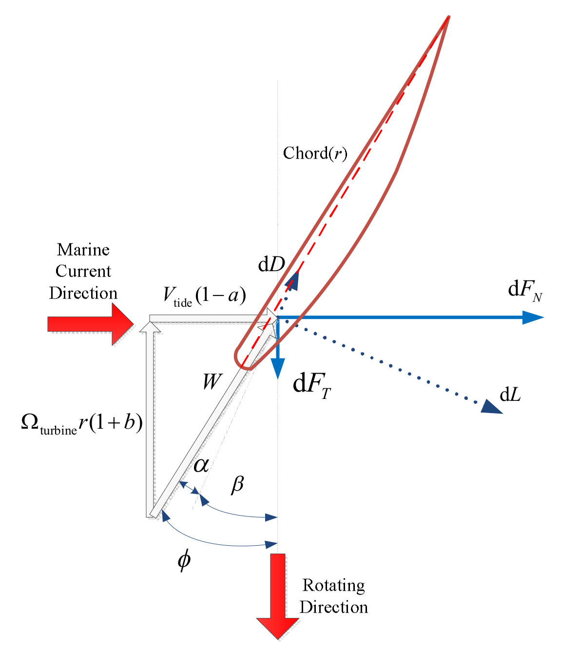
Figure 1. Blade section.
Jmse 08 00309 g001
Figure 2. Cp-TSR/λ curve with different pitch angles β.
Jmse 08 00309 g002
Figure 3. Diagram of torque-speed control strategy of DFIG.
Jmse 08 00309 g003
Figure 4. Range of IOPID and FOPID controllers.
Jmse 08 00309 g004
Figure 5. Bode diagrams of the open−loops with two controllers: (a) current loop; (b) speed loop.
Jmse 08 00309 g005
Figure 6. Performance of DFIG for FOPI (black) and IOPI (red) controllers with different settling time tsm: (a) DFIG speed; (b) electromagnetic torque; (c) rotor current amplitude; (d) active power.
Jmse 08 00309 g006
Figure 7. Bode diagrams of the speed open-loop with inaccurate mechanical model: (a) IOPI controller; (b) FOPI controller.
Jmse 08 00309 g007
Figure 8. Performance of DFIG for FOPI (black) and IOPI (red) controllers with the inaccurate mechanical model: (a) DFIG speed; (b) electromagnetic torque; (c) rotor current amplitude; (d) active power.
Jmse 08 00309 g008
Figure 9. Performance of DFIG for FOPI and IOPI controllers with variable marine tidal current speed: (a) DFIG speed; (b) electromagnetic torque; (c) rotor current amplitude; (d) active power.
Jmse 08 00309 g009
Figure 10. Marine tidal current speed regarding swell effect.
Jmse 08 00309 g010
Figure 11. Performance of DFIG for FOPI and IOPI controllers with swell effect: (a) DFIG speed; (b) electromagnetic torque; (c) rotor current amplitude; (d) active power.
Jmse 08 00309 g011