1. Introduction
The maritime industry are focusing more and more on power optimization, driven by a necessity to reduce fuel consumption and lower emissions [
1,
2,
3]. New innovations like including energy storage or direct current (DC) power systems have found their way on board many vessels [
4,
5]. DC grids can outperform alternating current (AC) grids in two areas: Power stability and economy [
4]. In a AC grid the generator frequency, and thus engine speed is fixed. The engine is designed to optimize at high load, where the fuel consumption is maximized. For lower loads the engine has a better fuel economy using a lower engine speed. This is where a DC grid with variable speed on the engine can be beneficial. Savings up to 30% for certain operations have been claimed [
6,
7].
However, some operations have much smaller benefits of variable-speed engines, or none at all. It is therefore an essential to perform a detailed assessment of the actual operational profile of the vessel in question. One type of vessel which can benefit from variable-speed engines are wind-farm support vessel. These vessels have a very specific operational profile with large variations in power demand in short time frames as well as requirements for power supply redundancy for dynamic positioning. A common solution on many of these vessels are diesel-electric power and propulsion systems with either a 50 Hz or 60 Hz electric frequency on the main switchboard.
This paper will look closer at a real world case of a wind-farm support vessel, the Edda Passat, based on the UT 540 WP design from Kongsberg Maritime [
8] (p. 9) delivered to Østensjø in 2018. While some vessels have utilized batteries for increased operational efficiency, the Edda Passat selected variable-speed engines as one of the key energy efficiency solutions. We have used three months of logged data of actual operations, and calculated the potential fuel savings compared to a fixed-speed engine setup. Thereby to confirm or disprove the benefits of this technology, this paper will give the reader an overview and a hands-on experience of variable-speed engines.
1.1. Vessel Description
Edda Passat is a mid-sized wind farm support vessel with a flexible design to meet the needs of specific farms, regions, and wind farm operators. These ships are equipped for accurate station-keeping and sensitive maneuvering in strong winds, currents, and waves. The transit speed is approximately 13 knots. The UT 540 WP meets special purpose ship rules [
9] with accommodation for up to 40 wind turbine technicians plus a ship crew of 20. The propulsion system is diesel-electric with four variable-speed engines connected to a local DC (direct current) grid—i.e., the main bus bars in the switchboard are DC. It also has a conventional AC (alternating current) grid feed from static converters that together ensure maximum flexibility and minimum fuel consumption. An arrangement plan for the ship is given in
Figure 1, with supplementary info in
Table 1.
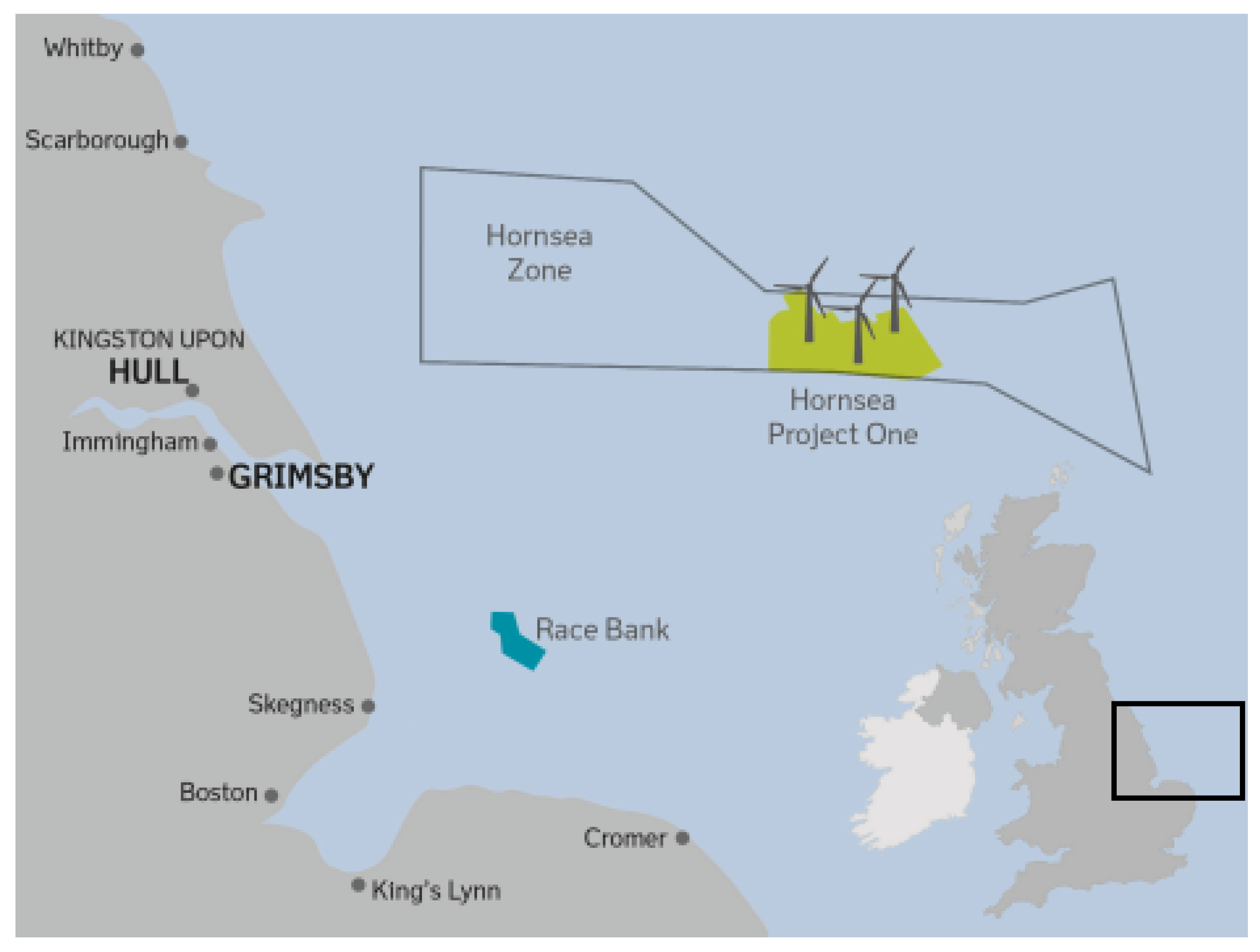
1.2. Wind Farm Cites and Vessel Operator
Østensjø is the owner and operator of Edda Passat [
10] and her sister vessel Edda Mistral [
11]. Østensjø runs the operation of the vessels used to support for operations and maintenance (O&M) for the Ørsted Race Bank and Hornsea wind farms in the North Sea, off the east coast of England (see
Figure 2). The Race Bank wind farm was completed in 2018 and consists of 91 turbines, with a full capacity of 573 MW [
12]. The final wind turbine for the first stage of the Hornsea wind farm, Project One, was installed in the fall of 2019 with the official inauguration planned for 2020. The Hornsea One wind farm consists of 174 turbines, each with 7 MW capacity, with the full capacity of the wind farm totalling over 1 GW [
13].
1.3. Methodology
The fuel consumption of diesel-engines depends on their load and speed (rpm). At the same load, a slower running engine can thus save fuel compared to an engine running at its full speed. We will explain this in more detail in
Section 2. By studying specific-fuel-consumption (SFC) curves from engine manufacturers it is possible to compare fuel differences between variable-speed and fixed-speed engine architectures.
A large amount of data is collected from Edda Passat every single second and with this, Kongsberg Maritime had the opportunity to do a real-world case study on the fuel-saving effect of using variable-speed engines. The three months (October, November, and December 2018) of logged data for engine power, rpm, SFC, and operational modes for all four engines on board the vessel gave us a full picture of the vessels fuel consumption history. The engine speed varied from 900 to 1800 rpm.
We then used this data to create a would-be scenario using fixed-speed engines instead. This was done by taking every single point which has a measured SFC, power, and rpm, and compared that with the same fuel consumption the engine would have had if the engine was operating at a fixed rpm of 1800 instead. We also adjusted for differences in power system architectures. A step-by-step description of our methodology is given in
Section 4.
2. Variable-Speed Engines
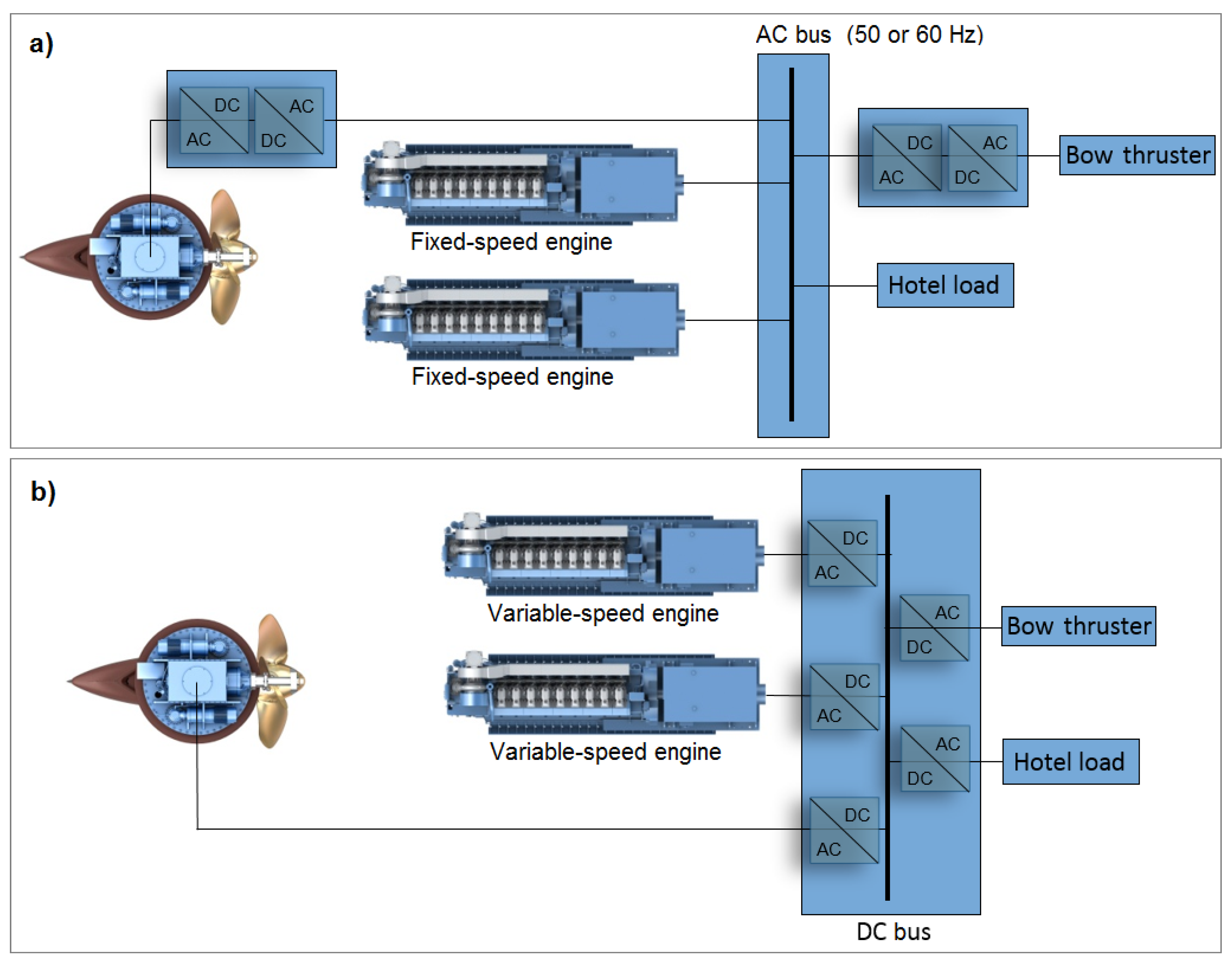
2.1. AC, DC, and Frequency Converters
The most common way to adjust the current frequency of the is by using a variable frequency drive (VFD) or an active front end (AFE). Both cases apply the same operating principles: AC is converted to DC via rectifiers (in VFD) or insulated gate bipolar transistors (in AFE), and then the DC is converted back to AC through an inverter. In both cases this is a two-step process; first AC/DC and then DC/AC, with the DC parts connected through a short internal link/bus.
A simple illustration of an AC power system is shown is
Figure 3a, where the generators, and all other components connected directly to the bus have the same fixed frequency (e.g., the hotel load). All components running at a different frequency (e.g., thrusters), require the two-step frequency conversion.
With a DC distribution system, one common DC bus is connected to all of the AC/DC converters. That is, the main bus bar in the switchboard utilizes DC and is linked to every other component via a DC/AC converter, thereby reducing the number of power conversion steps. This DC power system is illustrated in
Figure 3b. Ships with an energy storage system, such as batteries, can connect this directly to the DC bus. In the solution delivered by Kongsberg Maritime and used for Edda Passat, all the converters are grouped into one unit, called the SAVe Cube [
14]. This centralized DC switchboard also allows for a simpler cooling, signal, and control arrangements for the converters. Overall, the DC setup allows for optimised cost, size, and weight of the generator and rectifier [
15].
2.2. Why Use Variable-Speed Engines
Fixed-speed engines and generators comprise the conventional diesel-electric vessel setup where the engine must rotate at nominal speed to ensure that the generator supplies the AC switchboard with a fixed frequency. Most engines will have a peak efficiency at load-levels around 80%–100%. At load levels below this threshold, the fixed-speed engine will operate outside of its optimal design point on the torque-rpm curve, see e.g., [
3], leading to an increase in the SFC measured in g/kWh.
In general, an engine that can vary its speed has an efficiency improvement over a fixed-speed counterpart whenever the engine is operating at lower power requirements than nominal power. The lower the load, the higher the benefit, and significant fuel reductions were observed when operating at power levels below 80% nominal value. The variable-speed engine benefits is comparable to shifting gears in a conventional manual car. For optimal fuel efficiency, a car operator (driver) will utilize the highest gear possible, allowing the engine to operate on its lowest possible rpm, close to the stall-limit. It is the same logic for variable-speed engines on vessels—the engine fuel efficiency is maximized by running at the lowest possible rpm, at which it can delivered the required power.
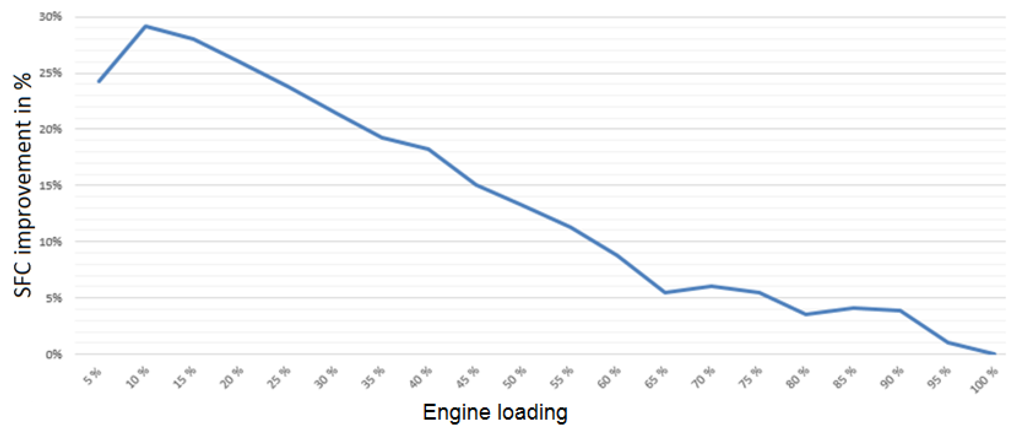
Figure 4 shows the measured SFC improvements for Edda Passat using variable-speed engines vs. an equivalent calculated fixed-speed engine setup. At 65% to 90% load we see a small (4%–6%) reduction in SFC. For engine loads lower than 65% there is a steady increase in fuel reduction as the engine loads decreases. The main benefit and reduction is seen at lower loads. It is common for this type of vessel to operate at 20%–25% engine load, and at this load level the fuel savings is found to be around 25%.
2.3. How to Use Variable-Speed Engines
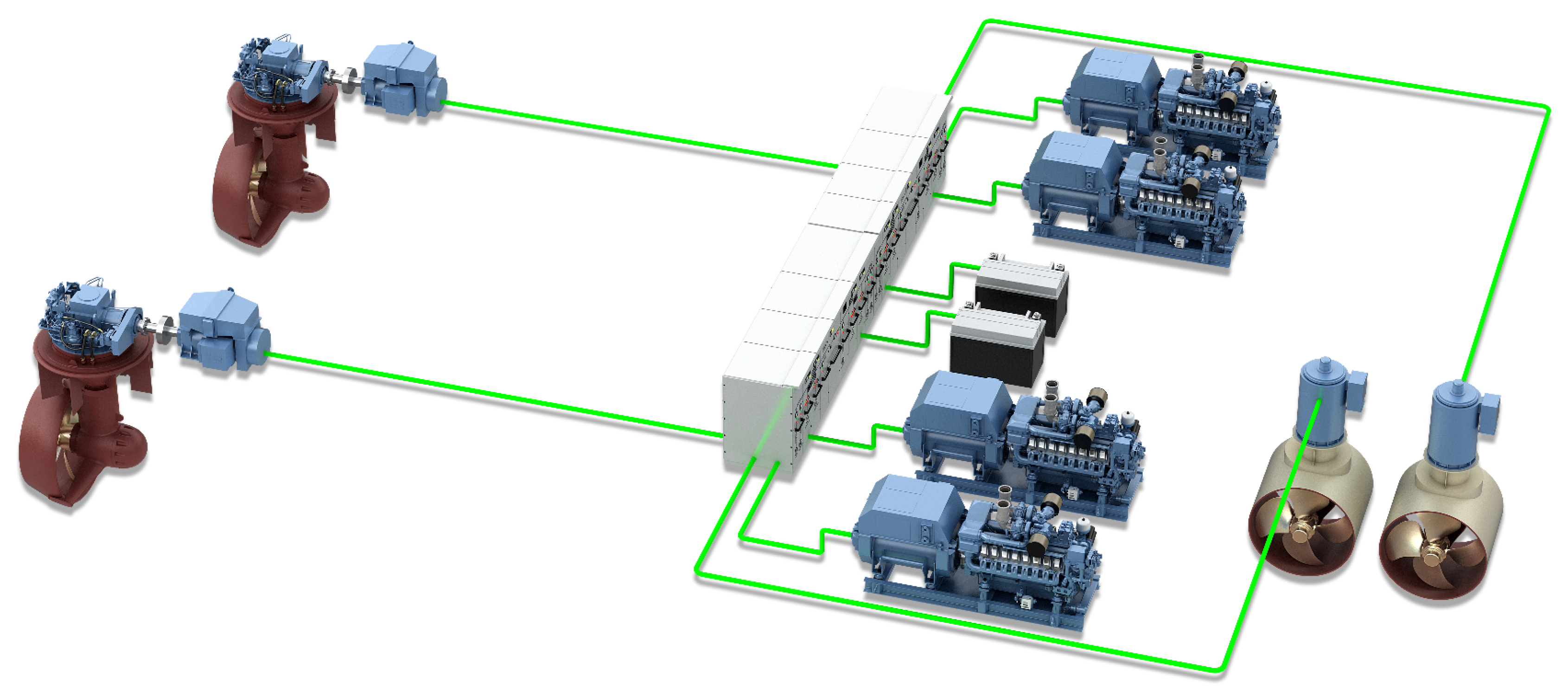
The key enabling technology for variable-speed engines is a DC grid. This can be either a distributed DC grid or a single integrated drive switchboard for the whole vessel utilizing a common DC-bus. The SAVe Cube, used on board the Edda Passat is the latter. All frequency converters, drives, and main switchboards are housed in a single cabinet for increased efficiency and space-saving footprint. The single cabinet also eases installation at the shipyard as many components are already integrated from the factory at delivery. This will, for instance, give a simpler, less distributed, cooling system.
Ship service power for hotel loads are powered from the same cabinet and supply conventional fixed frequency AC switchboards. Another benefit of the SAVe Cube is that heavy consumers with frequency controlled drives can be efficiently integrated onto the common DC-bus.
Figure 5 shows an illustration of a DC-distribution system.
2.4. When to Use Variable-Speed Engines
The main input for evaluating variable-speed engines on board a vessel is the operational profile, i.e., how the vessel is intended to be used. For offshore vessels like Edda Passat, it is also important to remember the various safety regulations, such as rules for dynamic positioning (DP) that set boundaries for how the power system on board is allowed to operate when performing specific tasks [
9]. For example, in DP1/class 1 there is no requirement for redundancy and thus loss of position may occur in the case of a single fault. DP2/class 2 requires redundancy in all active components (thrusters, generators, switchboards, etc., but not in static components like pipes, cables, etc.). To fulfill the DP2 power redundancy, either an energy storage system (battery) has to be available, or a second generator set has to be running and thus wasting fuel. When the operational profile for Edda Passat was evaluated in the design phase, the large number of operations in one of the DP modes and standby showed the potential benefit of variable-speed engines. The additional cost of the system was outweighed by the reduced fuel consumption. The measurement shown in
Section 4 quantifies these savings based on real measured data.
A typical operation for Edda Passat is a 14-day period in which it transits out to the wind farm field, operates inside and around the wind farm for 14 days and then sails back to its home port for a brief re-supply and crew change. During a typical day at the wind farm, the vessel operates in a mixture of short-term transit/manoeuvering between turbines and station-keeping with DP2 active to transfer service personnel at the turbine. At night it lays just outside the wind farm in standby, which is a station-keeping mode with DP1 rules, allowing a more relaxed redundancy level on the power and propulsion system.
2.5. Batteries (Energy Storage Systems)
It is worth mentioning that variable-speed engines do have some overlapping benefits with batteries [
4,
16,
17]. For some vessels, an energy storage solution gives the biggest benefit in engine performance, while for others, like Edda Passat, the biggest benefit was achieved by choosing variable-speed engines. Batteries were not chosen as the proposed solution for the Edda Passat due to its relatively short time in DP2 modes. In general, for offshore supply vessels, the biggest benefit of including batteries on board is to replace a diesel-powered generator as a redundancy option when in a DP2 mode, as discussed in
Section 2.4.
3. Profile of Edda Passat
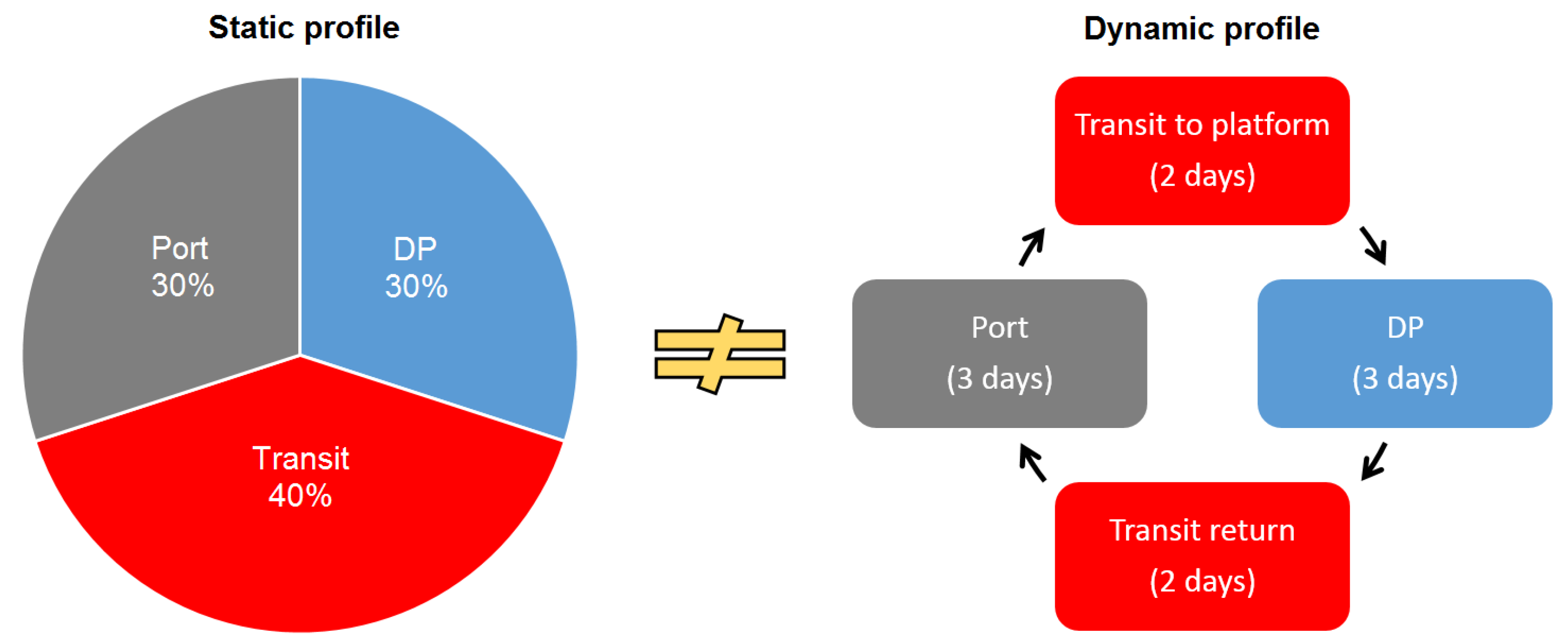
This section provides a basic summary of the Edda Passat, including an overview of vessel operation and configuration of the on board power system. It is critical in the design phase to evaluate dynamic operational profiles and not purely static profiles as illustrated in
Figure 6.
3.1. Tasks
The operational profile is a key aspects to any vessel design.
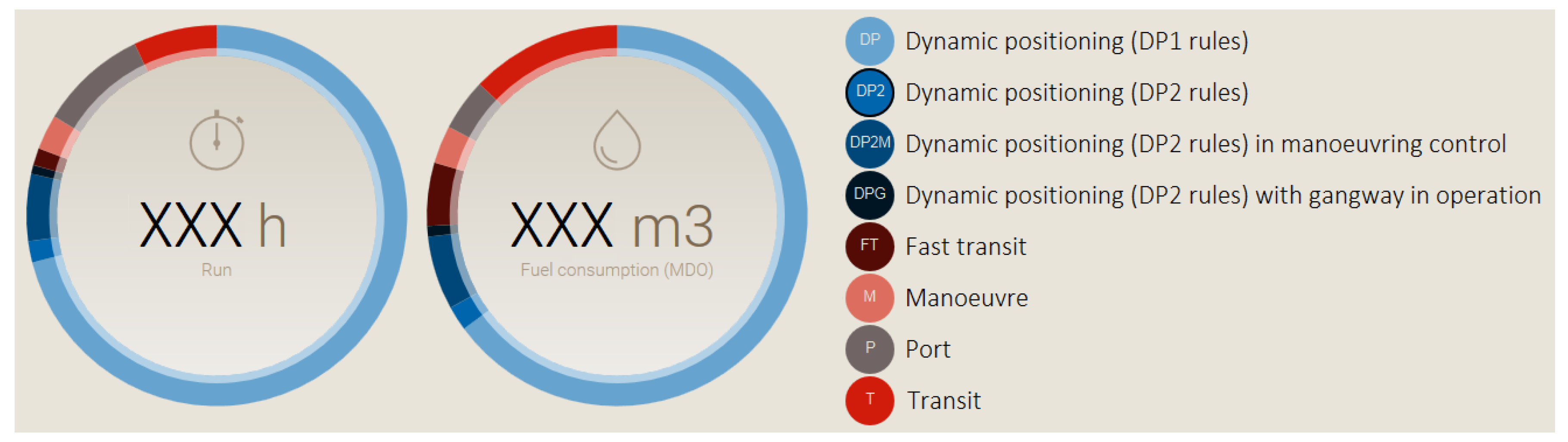
Figure 7 illustrates the logged static operational profile for Edda Passat from October to December 2018. It can be observed that a large amount of its operations, or around 70% of its total hours, is performed on the DP1 task when the vessel is in station-keeping outside the wind farm without the requirement of failure-redundancy required by DP2. In this operation, the vessel has a very low power consumption. This means that the power required can be generated efficiently by only one engine performing at a much lower operational speed than the nominal speed. The operational mode data used in
Figure 7 is an example of the operational data logged on the Edda Passat. The overall dataset for this quarter, comprises several million data points including position, power consumption, weather data, and velocity. This data range is utilized in the detailed operational performance evaluation provided in
Section 4. It should be noted that the presented percentages that the vessel operates in DP1 and DP2 may vary upon further maturity of the wind farms themselves and related maintenance operation.
3.2. Design
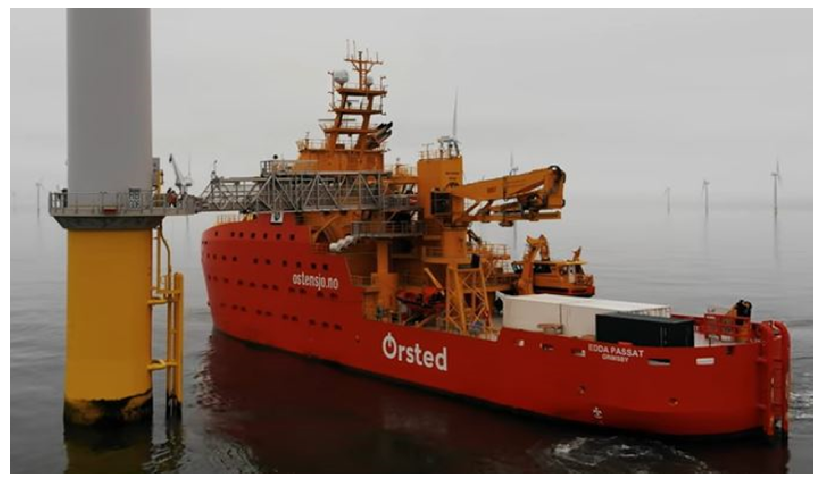
The Edda Passat and its sister vessel Edda Mistral are 82 m long service operation vessels (SOV), providing housing for up to 40 technicians and storage space for O&M equipment. The vessels are equipped with motion-compensated gangway systems, providing step-less access between the equipment storage areas and the turbine platform (shown in
Figure 8). The vessels are also equipped with a daughter craft, and both are used to transfer the technicians to turbines requiring maintenance and inspection. The vessel is also equipped with a 3D-motion compensated crane for the transfer of equipment to the turbines. The vessels are specifically designed for this type of operation with a focus on efficiency of the O&M support operations and comfort to the technicians.
3.3. Power System
The power and propulsion system on Edda Passat consists of four high-speed diesel generators (gensets) from the German manufacturer MTU, each rated at 2000 kWe. They deliver enough power for all of the tasks in the vessel’s operational profile. Using a diesel-electric setup instead of the configuration of a mechanical engine and propeller allows operators to shut off one or more engines without disabling propulsion, a significant benefit when the power demand from the propulsion units is low. Edda Passat also has three Kongsberg TT2000 SS CP tunnel thrusters in the bow, each rated at 925 kW with controllable pitch. These provide the required DP2 redundancy, ensuring positioning performance and accuracy.
4. Measured Results and Calculations
To calculate the fuel-savings achieved by using variable-speed engines on board Edda Passat we compared those real numbers with calculated estimates for a fixed-speed engine setup. The first part of our case study was to gather data from the vessel’s operational history. We used measurements for the engine power, engine rpm, and SFC for each of the four diesel engines. These 12 different measurements were then logged every second for October to December 2018. This data alone resulted in a data set consisting of 93 million data points. Other measurements, like vessel modes and speed, were employed to accurately separate and group the data. One way to group the data could be according the the operational modes, as described in shown
Figure 7, or, as we have done in this section, according the vessel’s speed.
The second step was to estimate how much fuel the ship would use if it were installed with fixed-speed engines in an AC based architecture. The general idea was to take every single point which has a measured SFC, power, and rpm, and comparing that with the same fuel consumption the engine would have had if the engine was operating at a fixed rpm of 1800 instead. However, we also needed to take into account the differences in energy-losses from generators to consumers between the the two architectures. For example, each step used through a frequency converter comes with a loss. The losses in the generators is also higher for lower speeds. We ended up with the following algorithm to calculate fuel consumption for fixed-speed engines:
Read engine-load (kW) used in variable-speed engine setup;
Adjust engine-load for different architecture;
Adjust for losses in generator which is higher at lower speeds;
Find SFC with this new engine-load at 1800 rpm.
The fuel saving were listed for each time-step in our data-set. The total fuel-saving or task-specific savings were found by integrating over the desired ranges. For this article we have chosen to focus on two main types of operations, namely transit (which we here define as speed over 0.4 knots) and station-keeping (speed less than 0.4 knots). For the latter case, we have not included time spent at harbor (harbor mode). These scenarios are discussed in
Section 4.1 and
Section 4.2, before the overall operations are investigated in
Section 4.3, each with accompanying plots (
Figure 9,
Figure 10 and
Figure 11). These plots show the SFC at different engines speed and power, together with a histogram at the bottom.
4.1. Transit
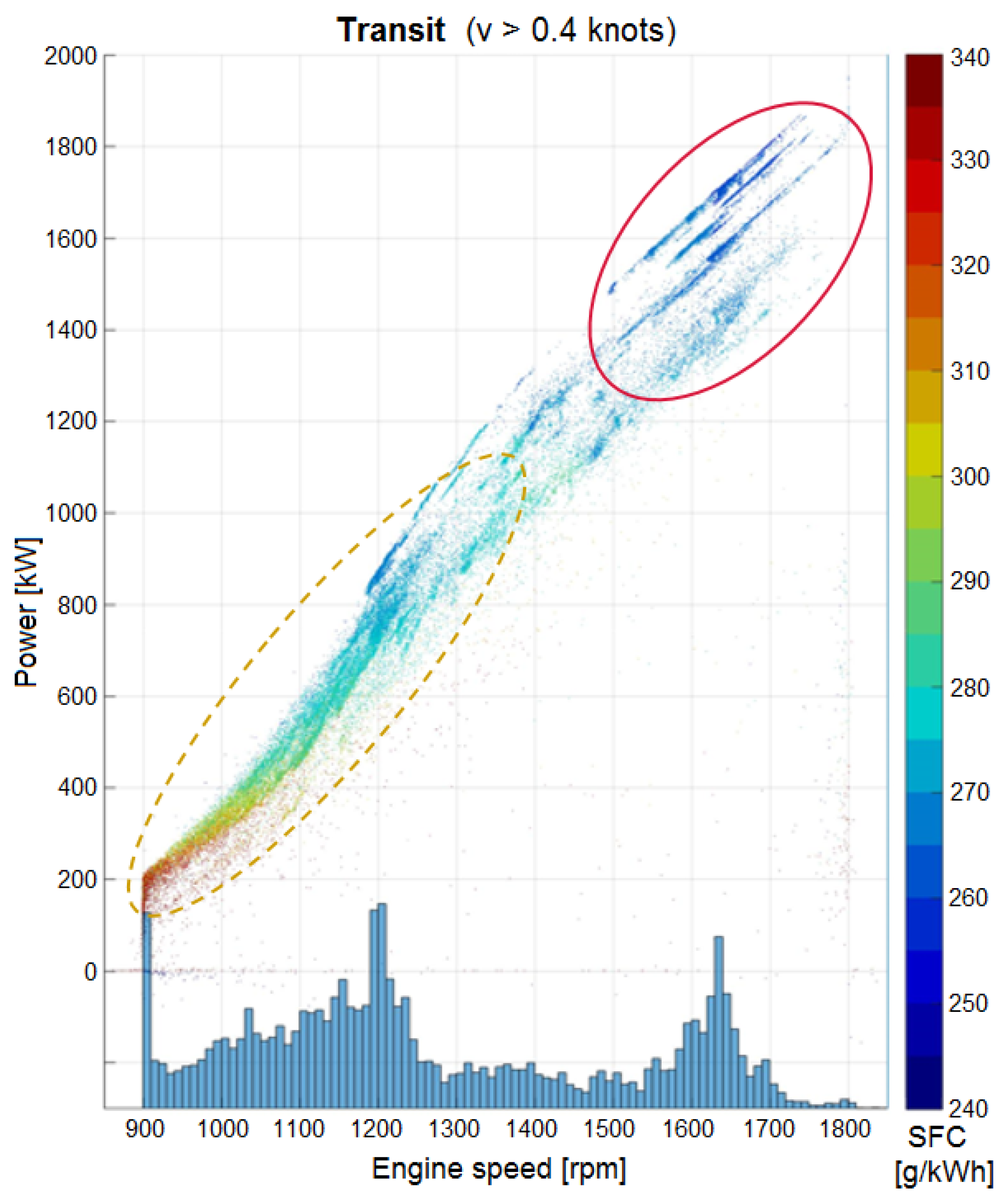
Edda Passat performs a wide range of transit operations. The typical transit scenario is either in the fortnightly transit trip to and from the wind farm, or the daily transit in-between turbines. The trips from harbor to the wind farms (and return) are typically performed at higher speed, marked with the red circle in
Figure 9, where the engines operate at a high load and the benefit of the variable-speed engines are limited. The large benefit is however noticeable in the daily transit closer to the wind farm, where the main fuel-savings are achieved. This is illustrated by the dashed orange circle in
Figure 9. For our evaluated period, most of Edda Passat’s engine speed lies between 900–1250 rpm, compared to the nominal speed of 1800 rpm, which the engine would have operated in with a traditional fixed-speed engine design. It is worth noting that there are large variations in the day-to-day transit operations inside the wind farm. The different power modes could be registered as manoeuver, DP, or transit-modes in the logged operational profile shown in
Figure 7.
Figure 9 illustrates the conditions of the engines under all operations where the vessel is sailing at a velocity greater than 0.4 knots.
If the power system used conventional AC switchboards, all of the measurements would have been seen along a vertical line at the 1800 rpm point on the x-axis. The total fuel saving on this setup mainly arise from the slower manoeuvering (orange dashed circle in
Figure 9) and, by using our procedure as explained in the beginning of this section, are calculated to be 15%. This is the pure benefit in transit above 0.4 knots from the variable-speed engines. The benefits are even greater for the station-keeping tasks described next.
4.2. Station-Keeping—Standby (DP1) and Work (DP2)
As seen in
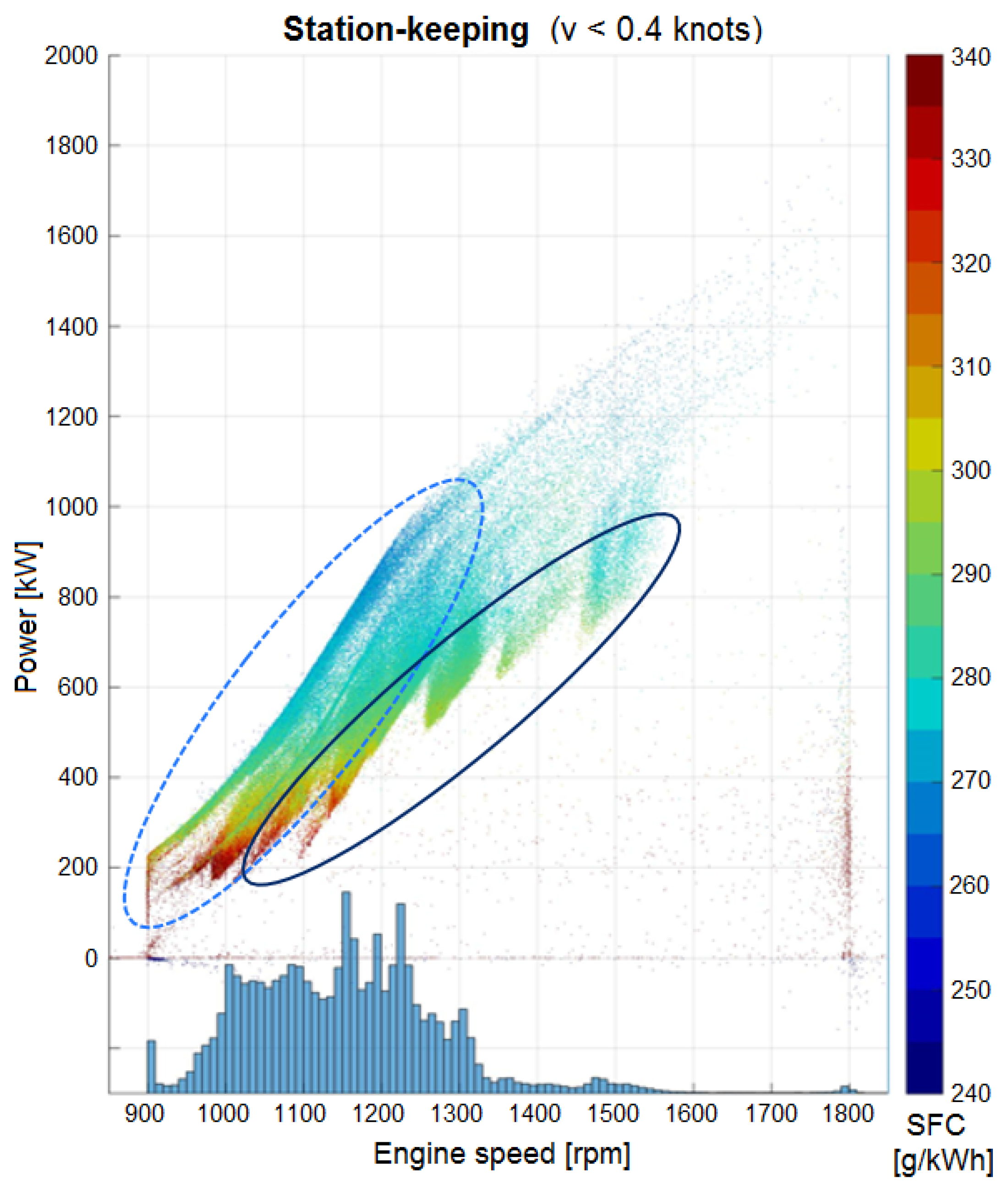
Figure 7, the biggest portion of the operations are performed in various DP-modes, where a large part of that is station-keeping. The measurements shown in
Figure 10 depicts the station-keeping operations that the Edda Passat has performed over the chosen three month period. Much of the station-keeping operations are performed in one of the DP-modes. DP1 and DP2 will have different operational requirements with regards to the number of engines running. This is observed in
Figure 10, where the light blue dashed area indicates most of the DP1-scenarios and the dark blue area indicates most of the DP2-scenarios. In DP2, the engines are run at non-optimal rpm as to increase the available instantaneous power. Most station-keeping operations have engine speeds below 1350 rpm. Both the DP1 and DP2 scenarios in station-keeping shows great fuel saving with variable-speed engines, with a total fuel saving of 24%.
In this section and the previous section, it can be seen that transit and station-keeping are the largest contributors to the fuel savings. Positive contributions to fuel savings arise from other operations as well, such as a port-stay without shore connection. The vessel demands a relatively small amount of power from the engine in this operation, thereby also allowing the engine to reduce rpm and improve the SFC as well.
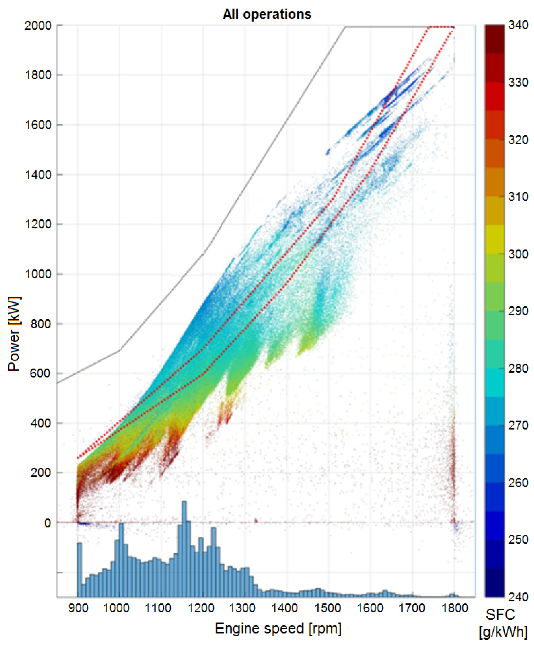
4.3. Overall Operation
The greatest interest lies in investigating the total benefit of installing the variable-speed engine solution. This should provide the true value of the system, and the overall evaluation is therefore extremely dependent on the operational profile and how the vessel was utilized. It is in general a challenge to accurately predict the operational profile in the design phase of a vessel, as this can be impacted by many factors. Changes in sea states and weather conditions throughout the seasons, for instance, have a large impact on the power requirements. The vessel can also change its operation during its lifetime, and this difference can be significant if the vessel started operating at a new wind farm where both the transit-distance and number of turbines varied. The SFC at different engine speeds and power for all operations for Edda Passat is shown in
Figure 11.
These are important factors to add, especially for vessels with a relatively high hotel load. Edda Passat’s hotel load makes up a fairly substantial part of the overall power, which means that the added losses from the hotel converters are important to include. In total, the variable-speed engine solution gives Edda Passat’s engines a fuel reduction of about 23% compared to the conventional setup. When the two mentioned effects of generator efficiency and hotel load are included, the total overall benefit for Edda Passat is about 21% for fuel savings. Another positive benefit is the lengthening of the engine life cycle due less wear and tear at a lower rpm.
5. Conclusions
Integrated or distributed DC grids for variable-speed engine systems are regarded as a suitable technology for SOVs, especially for vessels with a large portion of low-load operations. The measurements performed on the Edda Passat confirmed how variable-speed engines could lead to significant fuel savings, especially in station-keeping. Our results from the analyzed data estimated that the Edda Passat saved a total of 21% on fuel and 24% in the low-load station-keeping scenario.
Whether or not a variable-speed engine setup is a valid option for a vessel, depends on its operational profile. This is critical input to evaluate during the design of the power and propulsion system. However, it is essential to note there is always some uncertainty involved with a vessel’s operational profile. Environmental conditions together with changing missions and potentially new rules and requirements to fulfill can all significantly impact an operational profile, making it challenging to predict exactly how the vessel will operate. The results by this study on Edda Passat show a good margin for changes in a future operational profiles. Variable-speed engines is thus a good option for wind-farm support vessels with similar scenarios.
Author Contributions
Conceptualization: K.E.H., S.T., M.d.J.; methodology: K.E.H., S.T., M.d.J.; data investigation and formal analysis: K.E.H.; writing, review and editing: K.E.H, L.H., supervision: S.T., M.d.J. All authors have read and agreed to the published version of the manuscript.
Funding
This research was funded by the EU Horizon 2020 for the project NEXUS [
18] under agreement 744519, which aims to develop the next generation offshore wind farm support vessels. The project works to reduce costs and emissions through improved operational efficiency. This includes both considering solutions to improve vessel energy efficiency, and optimization of logistical maintenance planning. To achieve this, NEXUS explores ways to reduce power requirements for the service operation vessels (SOVs) and to diversify energy sources. This allows for better utilization of propulsion and auxiliary power plants, the main elements comprising the logistical concept for servicing wind farms. NEXUS investigates modern and emerging technologies from the point of view of energy saving potential, and use of advanced computational tools for operational planning and vessel control to reduce power the demand during the key operations of an SOV.
Acknowledgments
This paper would not have been possible without the support and data given from Østensjø on the operations of Edda Passat. We would also like to thank Joakim Kjølleberg for making our data plots.
Conflicts of Interest
The authors declare no conflict of interest.
References
- Lana, A.; Pinomaa, A.; Peltoniemi, P.; Lahtinen, J.; Lindh, T.; Montonen, J.H.; Tikkanen, K.; Pyrhönen, O.P. Methodology of Power Distribution System Design for Hybrid Short Sea Shipping. IEEE Trans. Ind. Electr. 2019, 66, 9591–9600. [Google Scholar] [CrossRef]
- Hansen, J.F.; Wendt, F. History and State of the Art in Commercial Electric Ship Propulsion, Integrated Power Systems, and Future Trends. Proc. IEEE 2015, 103, 2229–2242. [Google Scholar] [CrossRef]
- Dedes, E.K.; Hudson, D.A.; Turnock, S.R. Assessing the potential of hybrid energy technology to reduce exhaust emissions from global shipping. Energy Policy 2012, 40, 204–218. [Google Scholar] [CrossRef]
- Kim, K.; Park, K.; Roh, G.; Chun, K. DC-grid system for ships: A study of benefits and technical considerations. J. Int. Marit. Saf. Environ. Aff. Shipp. 2018, 2, 1–12. [Google Scholar] [CrossRef] [Green Version]
- Syverud, T.H. Modeling and Control of a DC-Grid Hybrid Power System with Battery and Variable Speed Diesel Generators. Master’s Thesis, Norwegian University of Science and Technology, Trondheim, Norway, 2016. [Google Scholar]
- ABB. The Step Forward—Onboard DC Grid; ABB Brochure: Zürich, Switzerland, 2014; Available online: https://new.abb.com/docs/librariesprovider91/articles/lm00614-onboard-dc-grid-brochure_june2014_1.pdf (accessed on 23 March 2020).
- Settemsdal, S.O.; Haugan, E.; Aagesen, K.; Zahedi, B.; Drilling, S.A. New Enhanced Safety Power Plant Solution for DP Vessels Operated in Closed Ring Configuration. In Proceedings of the MTS Dynamic Positioning Conference, Houston, TX, USA, 14–15 October 2014. [Google Scholar]
- Kongsberg Maritime, AS. Marine Products and Systems. Ref: MPS 13/03/2019–2. Available online: https://www.kongsberg.com/globalassets/maritime/km-products/documents/product-catalog-2019.pdf (accessed on 10 December 2019).
- Det Norske Veritas. Newbuildings, Special equipment and systems, Additional class, Part 6 Chapter 7, Dynamic Positioning Systems. In Rules for Classification of Ships; Det Norske Veritas: Høvik, Norway, 2012. [Google Scholar]
- Østensjø. Information on Edda Passat. Available online: https://ostensjo.no/fleet/eddapassat/ (accessed on 10 December 2019).
- Østensjø. Information on Edda Mistral. Available online: https://ostensjo.no/fleet/eddamistral/ (accessed on 10 December 2019).
- Ørsted AS. Full power at Race Bank Offshore Wind Farm. Available online: https://orsted.com/en/Media/Newsroom/News/2018/02/Full-power-at-Race-Bank-Offshore-Wind-Farm (accessed on 10 December 2019).
- Ørsted AS. Final Turbine Installed as World’S Largest Offshore Wind Farm Nears Completion. Available online: https://hornseaprojectone.co.uk/News/2019/10/Final-turbine-installed-as-worlds-largest-offshore-wind-farm-nears-completion (accessed on 10 December 2019).
- Kongsberg Maritime AS. Electrical Power SAVe Cube System. Available online: https://www.kongsberg.com/maritime/products/electrical-power-systems/electric-hybrid-propulsion/electrical-power-save-cube-system (accessed on 10 December 2019).
- Doerry, N.; Robey, H.; Amy, J.; Petry, C. Powering the Future with the Integrated Power System. Navan Eng. J. 1996, 108, 267–282. [Google Scholar] [CrossRef]
- Zahedi, B. Shipboard DC Hybrid Power Systems: Modeling, Efficiency Analysis and Stability Control. Ph.D. Thesis, Norges Teknisk-Naturvitenskapelige Universitet, Trondheim, Norway, 2014. [Google Scholar]
- DNV-GL. DNV GL Handbook for Maritime and Offshore Battery Systems; DNV-GL: Oslo, Norway, 2016; Available online: https://www.dnvgl.com/maritime/publications/maritime-and-offshore-battery-systemsdownload.html (accessed on 23 March 2020).
- NEXUS Project Homepage. Available online: https://www.nexus-project.eu/ (accessed on 28 August 2019).
© 2020 by the authors. Licensee MDPI, Basel, Switzerland. This article is an open access article distributed under the terms and conditions of the Creative Commons Attribution (CC BY) license (http://creativecommons.org/licenses/by/4.0/).


