Article

Progressive Collapse Analysis of Intact and Damaged Ships under Unsymmetrical Bending

Department of Naval Architecture and Ocean Engineering, Inha University, Incheon 22212, Korea
*
Author to whom correspondence should be addressed.
J. Mar. Sci. Eng. 2020, 8(12), 988; https://doi.org/10.3390/jmse8120988
Submission received: 11 November 2020 / Revised: 1 December 2020 / Accepted: 1 December 2020 / Published: 4 December 2020
(This article belongs to the Special Issue Accidental Limit States of Marine Structures)

Abstract

:
This study examined the hull girder strength of intact and damaged ships by adopting the incremental-iterative method for progressive collapse analysis, which was extended to the general case of the unsymmetrical bending of beams with an arbitrary cross-section. The sources of an unsymmetrical loading, including rotation of the loading plane and section asymmetry caused by structural damage, are described. A fast and robust procedure is presented to determine the translation and rotation of the instantaneous neutral axis at each curvature increment when applying Smith’s progressive collapse analysis method. A series of analyses were conducted on a double hull VLCC and a bulk carrier, considering various loading plane angles and damage conditions. The decrease in ultimate strength and the influences of rotation of the instantaneous neutral axis and ship heeling are discussed. The proposed method can be used for a rapid and rational assessment of the hull girder strength under adverse conditions.

1. Introduction

Fast and robust methods are needed to design ship hulls to withstand extreme wave-induced bending moments under both intact and damaged conditions. The residual strength under a damaged condition due to collision, grounding, or explosion/blast loading is an important research area, not only with regard to assessing the crashworthiness of a proposed hull girder structure but also for practically relevant applications considering the recoverability and survivability of damaged ships and how they are salvaged and rescued. A rapid and accurate method would be invaluable, particularly for naval vessels, whereby damage may be sustained in a hostile environment, and a quick assessment for determining the residual strength would be necessary for further engagement or evacuation.
The progressive collapse method, in which the principles were first introduced by Smith [1], is recognized as a relatively simple but accurate method for estimating the hull girder response under a vertical bending moment in intact and upright condition. Smith’s method originally follows a pure-incremental procedure using an incremental relationship between the bending moment and curvature based on the instantaneous tangent rigidity of a cross-section (tangential moduli formulation) and applying sufficiently small curvature increments [2]. Smith [3] and Smith and Pegg [4] described an extension of Smith’s method to bi-axial bending and unsymmetrical sections. Either fixed increments of curvature or moment can be applied in biaxial bending moment problems. On the other hand, the former method is less suitable because the proportion of horizontal and vertical bending moments would not follow a prescribed ratio, and a determination of the ultimate capacity would be cumbersome [4,5]. The latter method, applying incremental bending moments with a prescribed ratio to calculate vertical and horizontal curvature, is more appropriate for strength analysis, but its formulation breaks down when the ultimate bending moment is reached, and it cannot be applied to obtain a post-collapse response. Fujikubo et al. [5] reviewed the procedures for applying a pure-incremental method for various loading and constraining conditions.
In the IACS Common Structural Rules for Bulk Carriers and Oil Tankers (IACS-CSR) [6], Smith’s method is incorporated for an ultimate capacity assessment of a hull girder using an incremental-iterative approach, whereby curvature is applied incrementally. The vertical position of the instantaneous neutral axis from the baseline is determined iteratively by imposing a zero-axial force condition. Gordo and Guedes Soares [7] applied this approach and extended it to deal with biaxial bending by applying a fixed curvature ratio [8]. In addition, Gordo and Guedes Soares [9] applied the incremental-iterative method to calculate the ultimate strength of damaged ships. Structural damage was modeled by simply removing various elements from within the transverse cross-section of a hull girder. This approach was adopted in several studies [10,11,12,13,14], and incorporated in IACS-CSR without explicitly considering the problem as unsymmetrical bending. The IACS-CSR prescribes a mandatory check of the ship hull-girder residual ultimate strength under a vertical bending moment.
Unsymmetrical bending arises either if the bending moment does not act in a plane of symmetry or if a cross-section is unsymmetrical (does not have any axis of symmetry). In both cases, the axis of bending does not coincide with the neutral axis. In the context of a ship hull girder, these conditions correspond to the heeling of the ship and the loss of cross-sectional symmetry due to structural damage. Note that in the case of a ship collision and grounding, the ship may list such that both conditions will be present due to oil outflow or water ingress. As noted by Choung et al. [15], in progressive collapse under unsymmetrical bending, the neutral axis not only shifts vertically but also rotates at each increment because certain parts of the section buckle and yield. When using the incremental-iterative method, an additional condition is required to determine the correct position of the instantaneous neutral axis. This condition is related to the internal bending moment, which must act in the same direction as the external bending moment. Choung et al. [15] incorporated this condition in Smith’s method and applied it to analyze a double hull tanker [16]. Campanile et al. [17,18] and Tekgoz et al. [19] formulated this additional condition in a slightly different way and applied the extended Smith’s method to assess the residual strength of various merchant ship types. Zhu et al. [20] highlighted the need for robust solution procedures when the rotation of the neutral axis is considered in the incremental-iterative method. Fujikubo et al. [5] derived an explicit expression for rotating the neutral axis within the pure-incremental method and examined its influence on the residual strength of damaged ships. Makouei et al. [21] and, more recently, Kuznecovs et al. [22] adopted this analysis method to study the hull girder residual strength. The general conclusion derived from these studies is that constraining the rotation of the neutral axis in progressive collapse analysis causes overestimation of the residual strength. On the other hand, the degree of this influence is dependent on the type and extent of damage, ship type, and heeling condition. Parunov et al. [23] reported that IACS-CSR applies a fixed reduction of 10% on the ultimate strength of a hull girder with collision damage when predicting it with the incremental-iterative method without considering the rotation of the neutral axis. Therefore, this prescribed reduction ratio is not fully justified, and more research on this topic will be needed to develop the appropriate guidelines for ultimate strength assessments under adverse conditions.
In light of recent research, the object of the present paper was to describe precisely the procedure for applying the incremental-iterative method when a hull girder is subjected to unsymmetrical bending. In addition, a systematic examination of the influence of rotation of the neutral axis under various loading and damage conditions is presented for the case of a double-hull oil tanker and a bulk carrier.

2. Method of Analysis

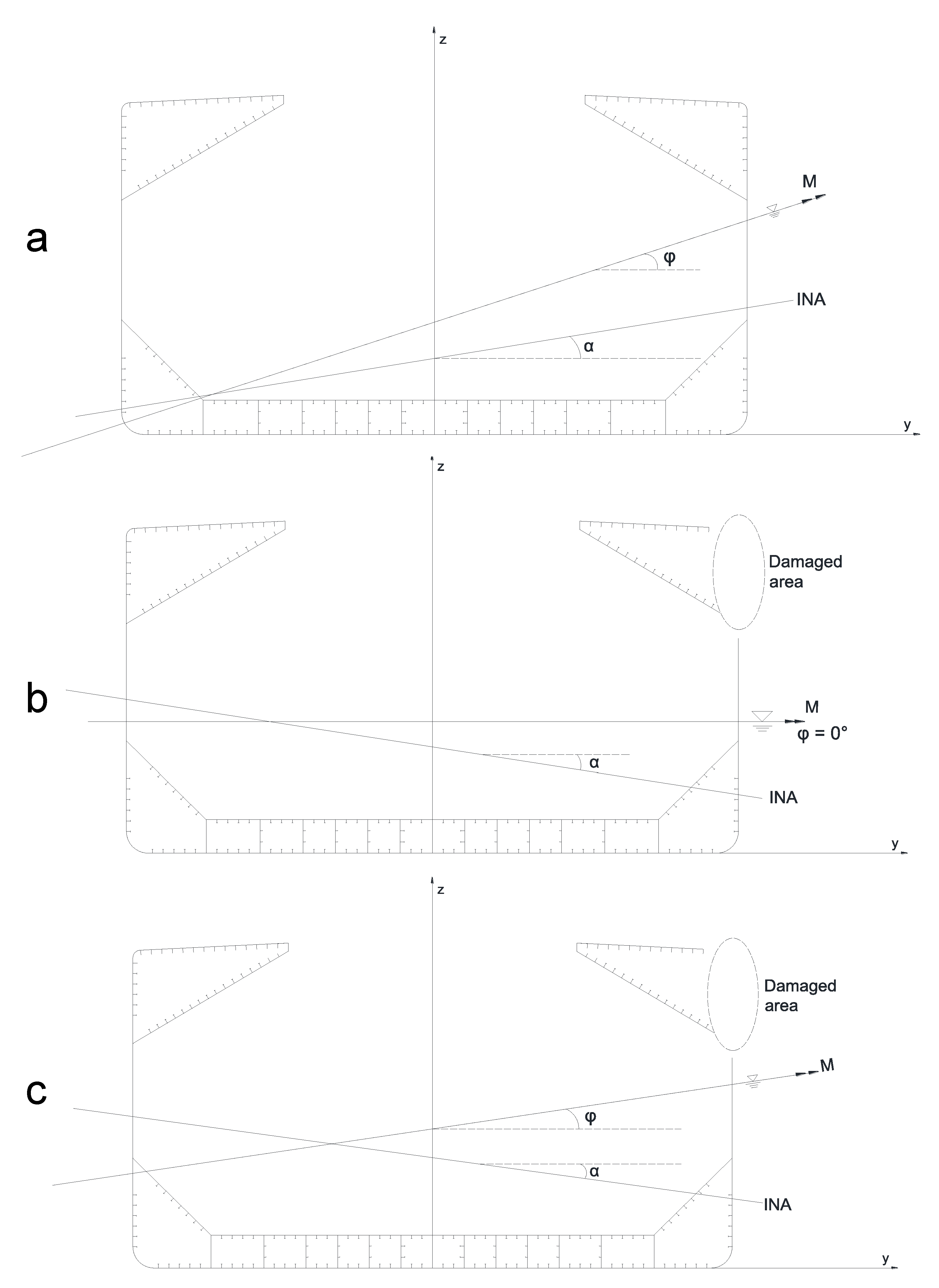
2.1. Elastic Response under Unsymmetrical Bending

Figure 1 presents three possible cases of unsymmetrical bending of a ship hull girder, where the neutral axis does not coincide with the axis of bending. Here, α denotes the angle between the neutral axis and the global y-axis (neutral axis angle), and φ indicates the angle of the bending axis (angle of the moment vector). Both angles are counter-clockwise positive. Note that φ also corresponds to the heeling angle of the ship as the axis of bending is always parallel to the water surface. The resultant bending moment, M, can be resolved into vertical and horizontal components, M y and M z , using the angle of the axis of bending:
M z = M sin ( φ )
M y = M cos ( φ )
tan ( φ ) = M z M y
For the most general case of unsymmetrical bending in elastic regime, where both the beam cross-section is not symmetrical and the applied couple is not directed along a principal centroidal axis, the axial stress at any point in the beam cross-section can be obtained using the following formula:
σ x ( y , z ) = ( M y I z ¯ + M z I y ¯ z ¯ ) z ( M z I y ¯ + M y I y ¯ z ¯ ) y I y ¯ I z ¯ I y ¯ z ¯ 2
where I y ¯ and I z ¯ denote the second moment of the area with respect to the elastic horizontal and vertical neutral axis, respectively, and I y ¯ z ¯ is the product moment with respect to the elastic neutral axes.
The following well-known equation is obtained after equating the stress formula to zero and noting that z = tan ( φ ) y :
tan ( α ) = tan ( φ ) I y ¯ + I y ¯ z ¯ I z ¯ + tan ( φ ) I y ¯ z ¯
The case of an intact ship under the heeled condition (Figure 1a) corresponds to the unsymmetrical bending of a beam with a symmetrical cross-section. Because of sectional symmetry I y ¯ z ¯ = 0 , the above relationship between these two angles simplifies to the following [8]:
tan ( α ) = tan ( ϕ ) I y ¯ I z ¯
For the case of a damaged ship in the upright condition (Figure 1b), I y ¯ z ¯ 0 and φ = 0 , and Equation (5) can be written as follows [17]:
tan ( α ) = I y ¯ z ¯ I z ¯

2.2. Progressive Collapse under Unsymmetrical Bending

The fundamental assumptions in Smith’s method are as follows:
  • The cross-sections remain in the plane (Navier’s hypothesis);
  • The hull girder collapses between two transverse frames (interframe collapse);
  • The structural units act independently.
Based on these assumptions, the procedure of applying Smith’s method starts with dividing the longitudinally effective hull girder cross-section into small elements (plate-stiffener combinations, plates, and hard corner/intersection elements). Each element needs to be assigned an average axial stress-strain curve that describes its response under uniaxial tension and compression. The next steps in the standard procedure of Smith’s method for symmetrical bending are as follows.
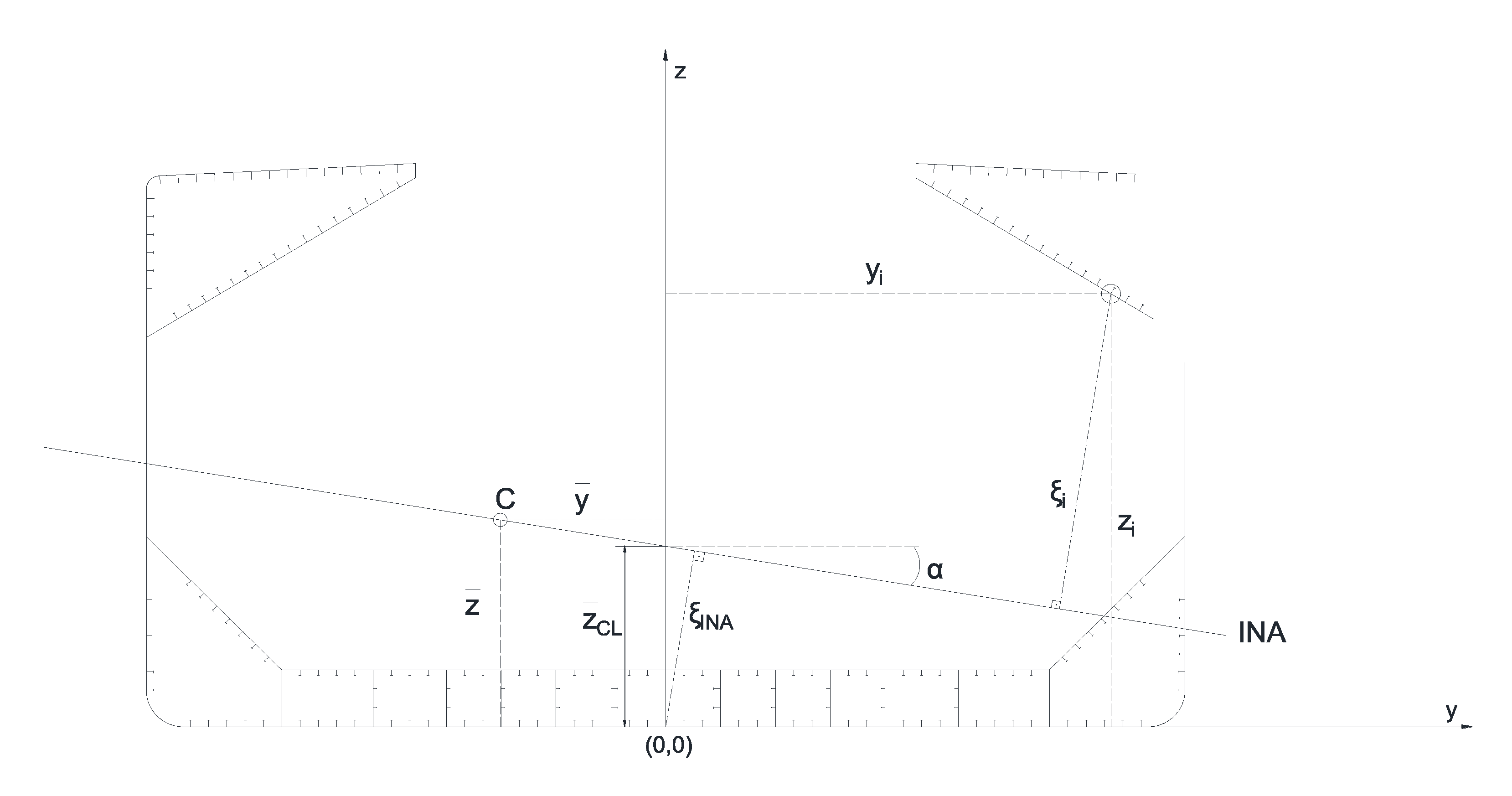
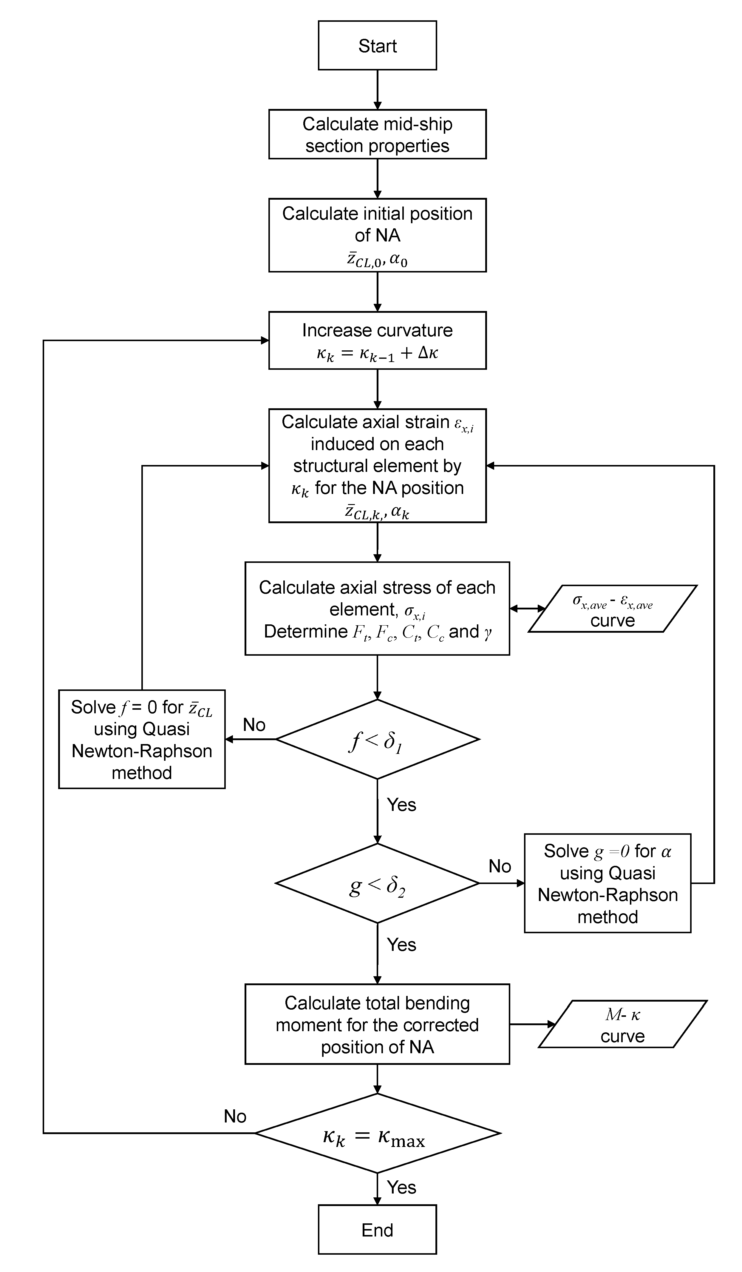
  • Calculate the initial position of the neutral axis and apply incremental curvature about this instantaneous neutral axis (INA).
  • Following the first fundamental assumption of Smith’s method, calculate the strain for each structural unit with respect to its vertical position and obtain the axial strain using the provided average stress-strain data.
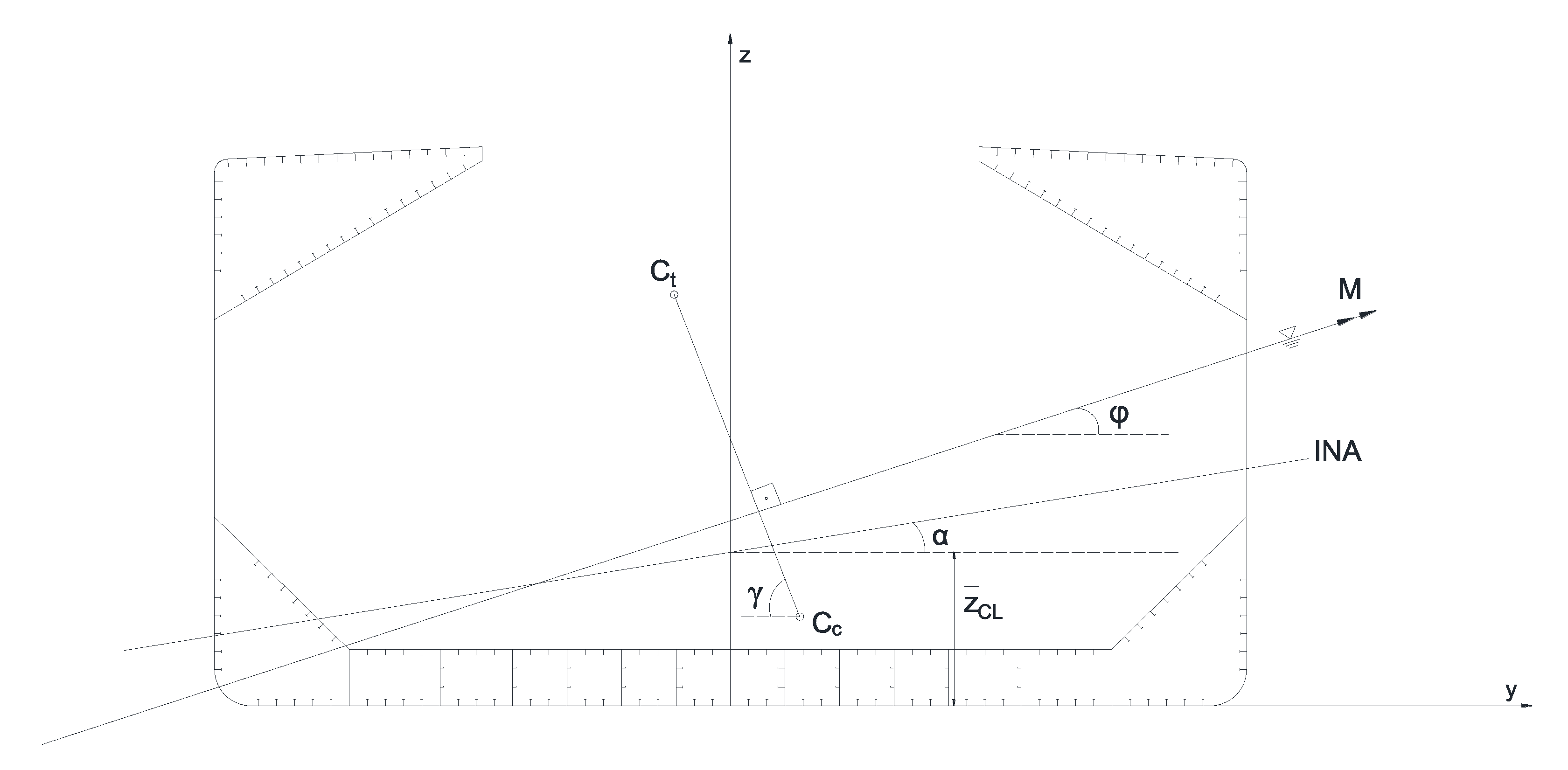
  • Integrate the axial stresses over the entire cross-section to obtain the bending moment.
  • In each increment of curvature, find the position instantaneous neutral axis, and follow the above steps until the target curvature, κ m a x is reached.
To apply Smith’s method to unsymmetrical bending, the position of the instantaneous neutral axis (INA) at any incremental curvature should be defined with two parameters. Figure 2 shows the coordinate system required to apply Smith’s method to unsymmetrical bending [17,24]. The neutral axis position at any increment of curvature, κ k , is defined as the vertical distance from the intersection of INA and centreline (CL) to the baseline (BL), z ¯ C L ( κ k ) , and with the angle, α ( κ k ) . Here, k defines the index of the increment.
At the start of the progressive collapse analysis, the elastic neutral axis of the cross-section is used. With reference to Figure 2, to obtain z ¯ C L , 0 , the coordinates of the elastic centroid of the cross-section C, can be used as follows:
z ¯ C L , 0 = z ¯ y ¯ tan ( α 0 )
The angle of the elastic neutral axis, α 0 , can be obtained using Equation (5) by inputting the cross-sectional properties and angle of the axis of bending.
The axial strain in each element requires determining the perpendicular distance from the respective element to INA. With respect to Figure 2, the following expressions can be derived:
ξ I N A = z ¯ C L cos ( α )
ξ i = z i cos ( α ) y i sin ( α ) ξ I N A
where ( z i , y i ) are the coordinates of the centroid of the element. The axial strain is then obtained as follows:
ε x , i = κ ξ i
Calculation of the axial stress of each element, σ x , i , requires a normalized load-end shortening/lengthening curves (average axial stress-strain, σ x , a v e - ε x , a v e curves). In this study, the simple formulae given in IACS-CSR [6] were used to define the load-end shortening curves, and elastic-perfect plastic behavior was assumed for the tension response of the structural elements.
According to the simple beam theory, the net resultant axial force on the beam section should be zero. This condition can be expressed as
i = 1 m σ x , i A i = 0
where A i is the cross-sectional area of the structural element, and m is the total number of structural elements. Alternatively, this condition can be expressed in terms of the net resultant tension force, F t , and the net resultant compression force, F c :
F t = σ x , i A i for σ x , i > 0
F c = σ x , i A i for σ x , i < 0
These two resultant forces should be equal:
F c = F t
In the incremental-iterative method, the zero-net axial force condition is used to determine the correct vertical position of INA, z ¯ C L ; it is more appropriate to express this condition as follows:
f ( z ¯ C L ) = | ( F c F t ) / ( F c + F t ) | = 0
This equation can be solved iteratively using a quasi-Newton-Raphson method (for example, the secant method). The iterative scheme can be expressed as
z ¯ C L , i + 1 = z ¯ C L , i f ( z ¯ C L , i ) f ( z ¯ C L , i )
Here, the derivative in the denominator is calculated numerically using a first-order forward difference type finite difference method. The iterations are stopped if f < δ 1 , where δ 1 is the specified tolerance. Based on the authors’ experience, δ 1 should be in the order of 1 × 10 7 .
With reference to Figure 3, the resultant tensile force, F t , is located at the centroid, C t , of the tensile area, A t . Similarly, the resultant compressive force, F c , is located at the centroid, C c of the tensile area, A c . The coordinates of the centroids can be determined easily as follows:
A t = A i for σ x , i > 0
A c = A i for σ x , i < 0
A t , z ¯ = A i z i for σ x , i > 0
A c , z ¯ = A i z i for σ x , i < 0
A t , y ¯ = A i y i for σ x , i > 0
A c , y ¯ = A i y i for σ x , i < 0
C t , z = A t , z ¯ / F t
C t , y = A t , y ¯ / F t
C c , z = A c , z ¯ / F c
C c , y = A c , y ¯ / F c
Here, C t , z and C t , y denote the z and y coordinates of C t , respectively. Similarly, C c , z and C c , y denote the z and y coordinates of C c , respectively.
A plane through the centroids, C t and C c , is the plane of the loads for the beam. Therefore, the angle associated with this plane must correspond to the direction of the external bending moment. From Figure 3, this condition can be expressed using the angle γ as follows:
γ = π / 2 if | C c , y C t , y | = 0 arctan | C c , z C t , z | | C c , y C t , y | else
g ( α ) = ϕ γ π / 2 = 0 for α 0 ϕ γ + π / 2 = 0 for α < 0
A quasi-Newton–Raphson method is used to solve this equation to find the correct orientation of NA. The iterative scheme can be expressed as
α i + 1 = α i g ( α i ) g ( α i )
The derivative g is calculated numerically using a first-order forward difference type finite difference method. The iterations are stopped if g < δ 2 , where δ 2 is the specified tolerance. δ 2 is recommended to be in the order of 1 × 10 3 .
Once the correct location and orientation of the neutral axis in terms of the vertical distance z ¯ C L and angle α , is known, the total bending moment can be calculated for the given curvature, κ k :
M = i = 1 m σ x , i A i ξ i
Note that M always acts perpendicular to the water plane.
Figure 4 presents the proposed procedure for progressive collapse analysis of ships under unsymmetrical bending. The proposed method of analysis is implemented in an in-house code. When applied to the analysis of typical merchant ships, as presented in the next section, the in-house code usually yields the results in less than one minute, without convergence issues. Note that unloading can occur in the yielded elements at certain increments due to rotation of the neutral axis. In such a case, the stiffness of those elements is restored to elastic axial stiffness.

3. Applications

The proposed method is applied for evaluating the progressive collapse behavior of ISSC double hull VLCC and Bulk Carrier benchmark models, which are described in [25,26]. Table 1 lists the main particulars of these two ships.
To evaluate the damage scenarios, accurate information on the extents of damage caused by accidents and the influence of structural discontinuities can be obtained by non-linear finite element analysis [27,28,29,30,31]. In this study, however, following IACS-CSR [6], the damaged structural elements are assumed to be completely ineffective. Note that this assumption may be rather conservative.
Both collision and grounding damage were considered following the definitions given in IACS-CSR [6]. In the case of collision damage, the damage is located on the deck-side shell intersection. The transverse damage extent was assumed to be B / 16 for both double hull VLCC and Bulk Carrier, where B is moulded breadth. The vertical damage extent was given as 0.75 D and 0.6 D for a single side and double sides, respectively. Here, D denotes the depth of the ship. In the present study, additional vertical damage extents are considered to be 0.2 D and 0.4 D . For the case of grounding damage, IACS-CSR assumes that the damage penetration height is a minimum of B / 20 and 2 m. The breadth (transverse extent) of the damage is to be taken as 0.60 B for both tankers and bulk carriers. In the present study, an additional two cases are considered to be 0.2 B and 0.4 B . The transversal position was assumed as the center of the ship because it yields the most unfavorable case. Figure 5 and Figure 6 show the damage extents of the double hull VLCC tanker for collision and grounding scenarios, respectively. Figure 7 and Figure 8 show the damage extents of a bulk carrier for collision and grounding scenarios, respectively.

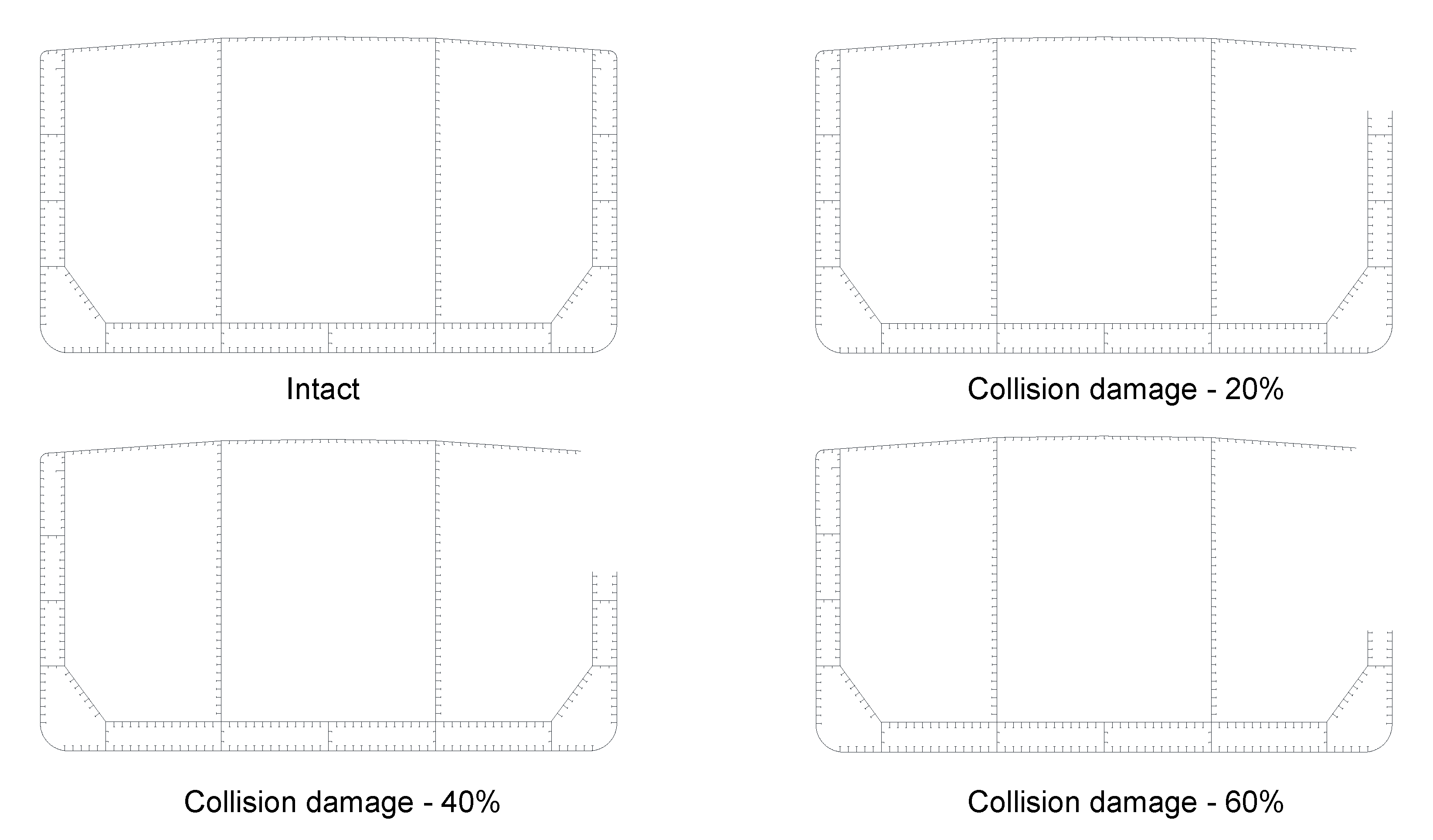
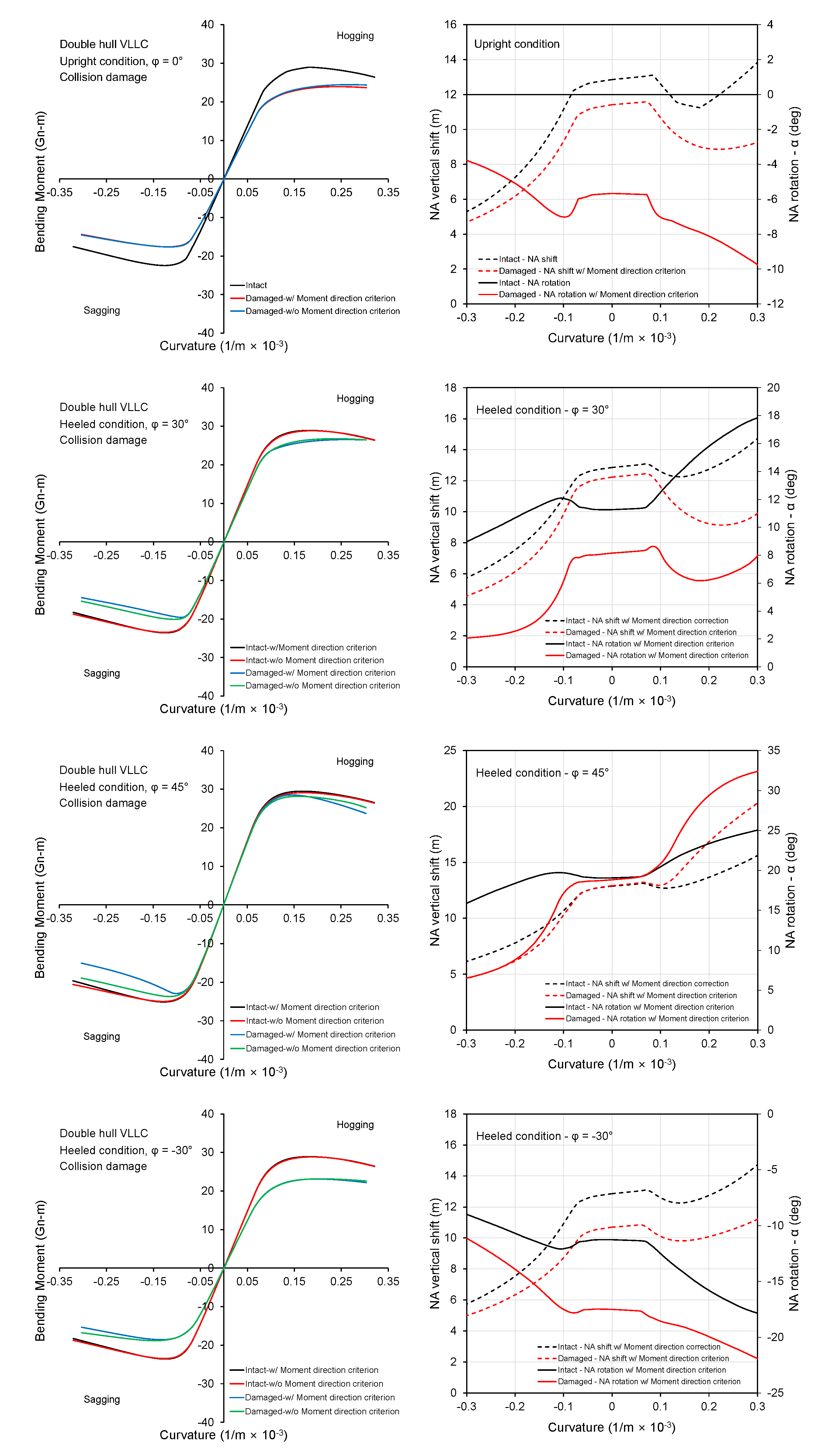
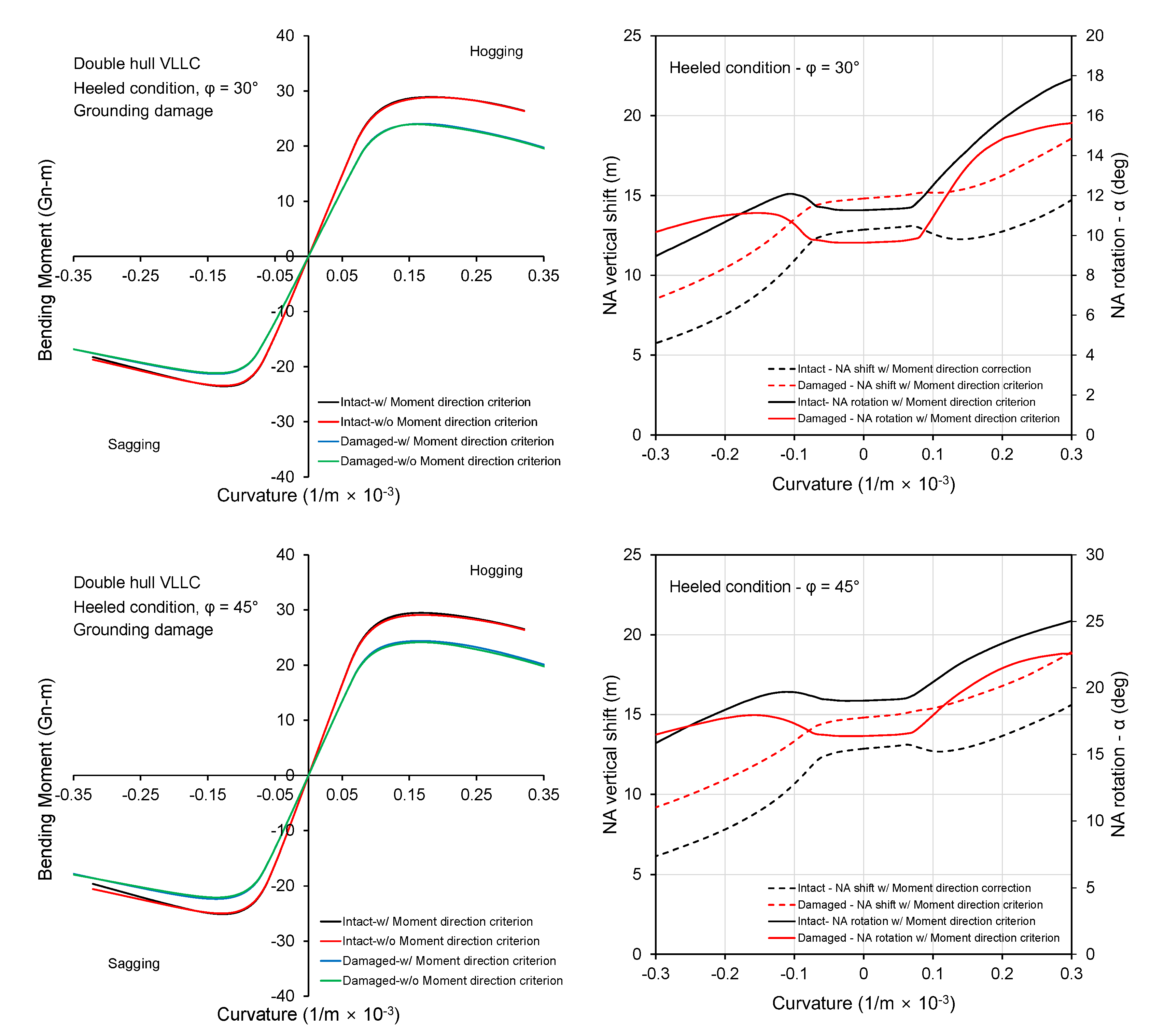
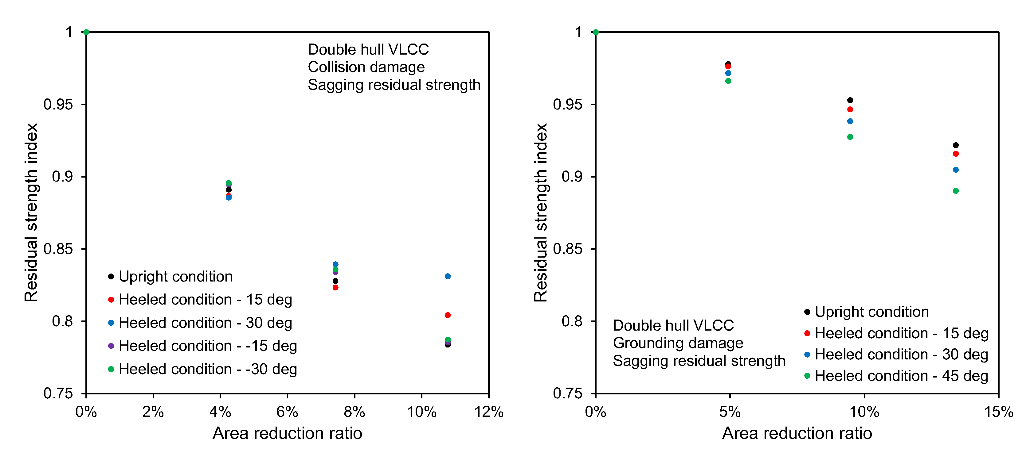
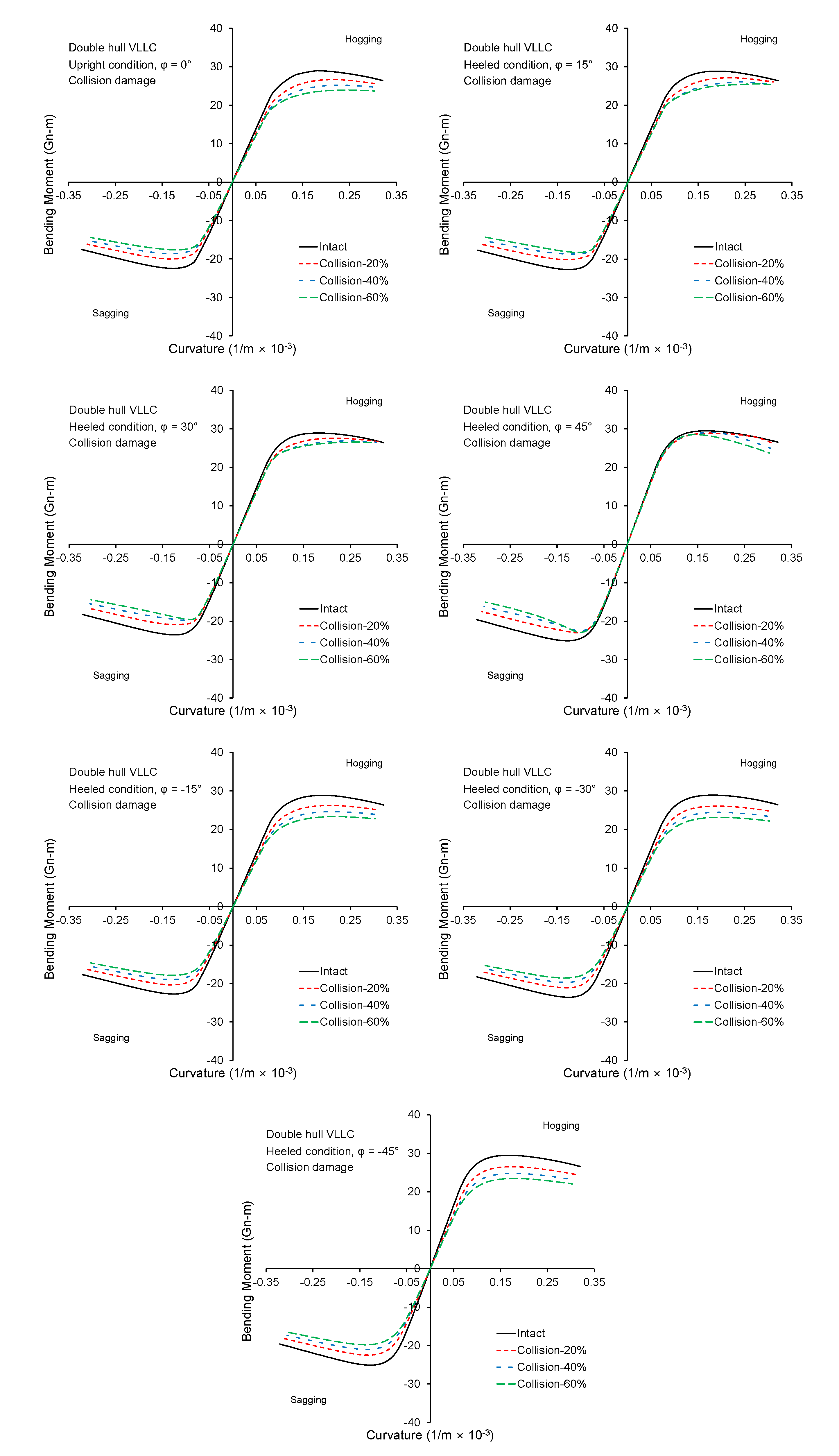
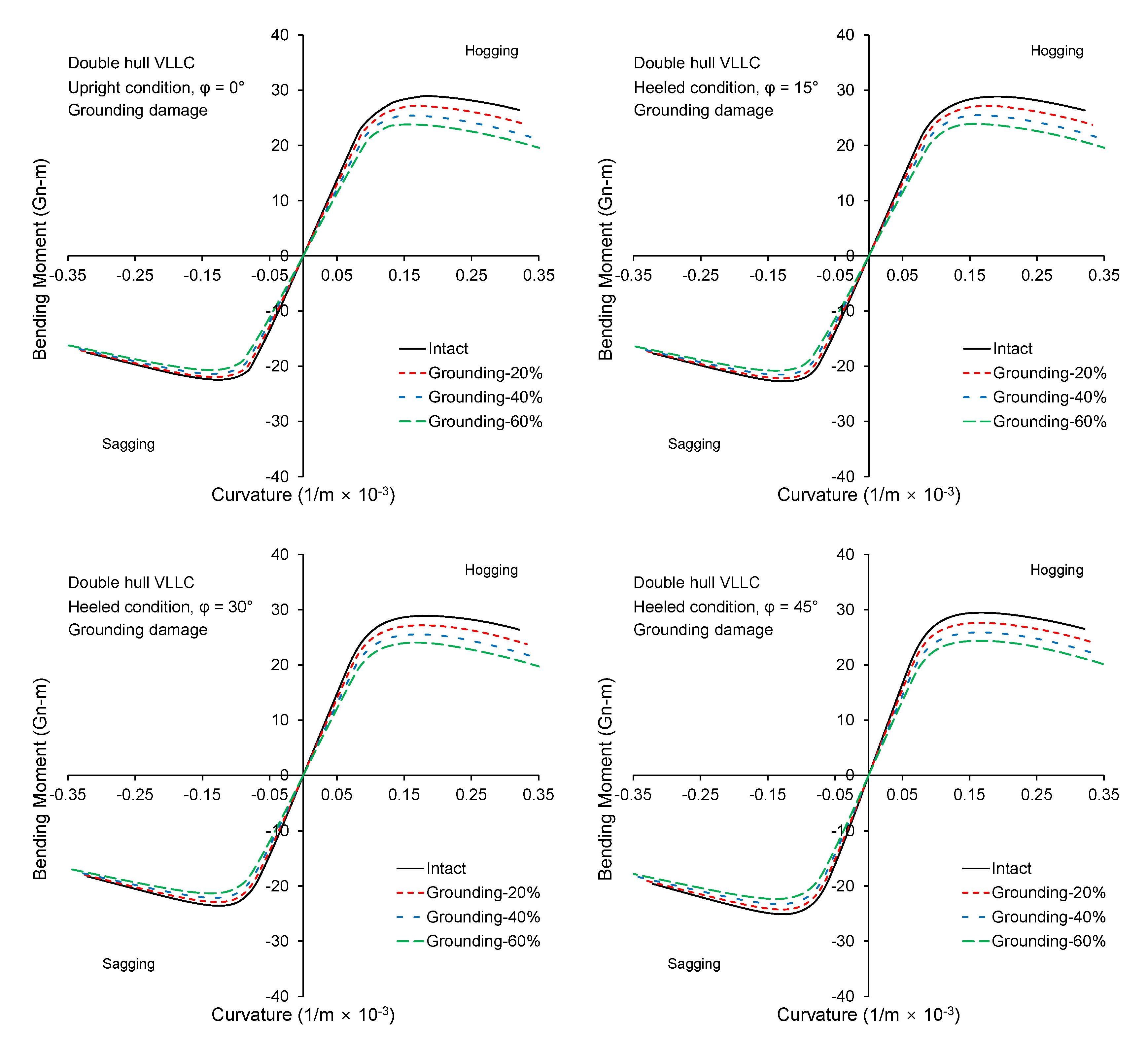
3.1. Double Hull VLCC
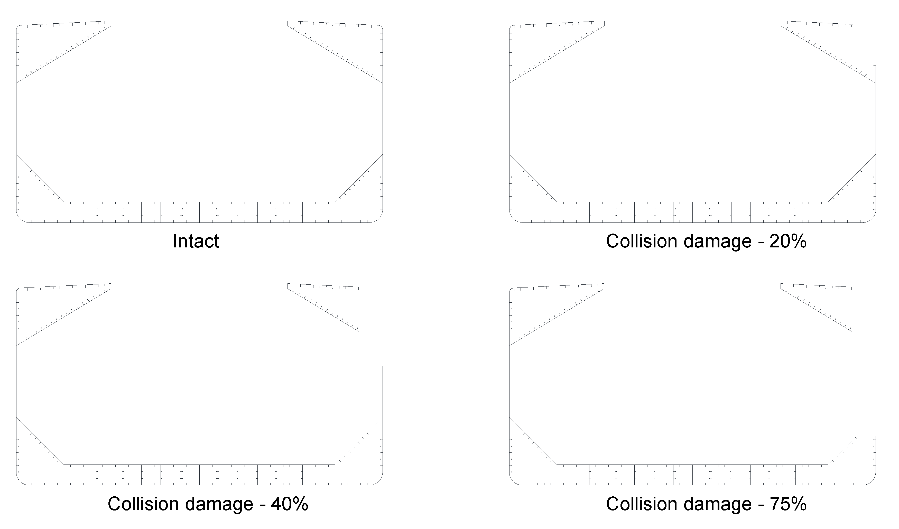
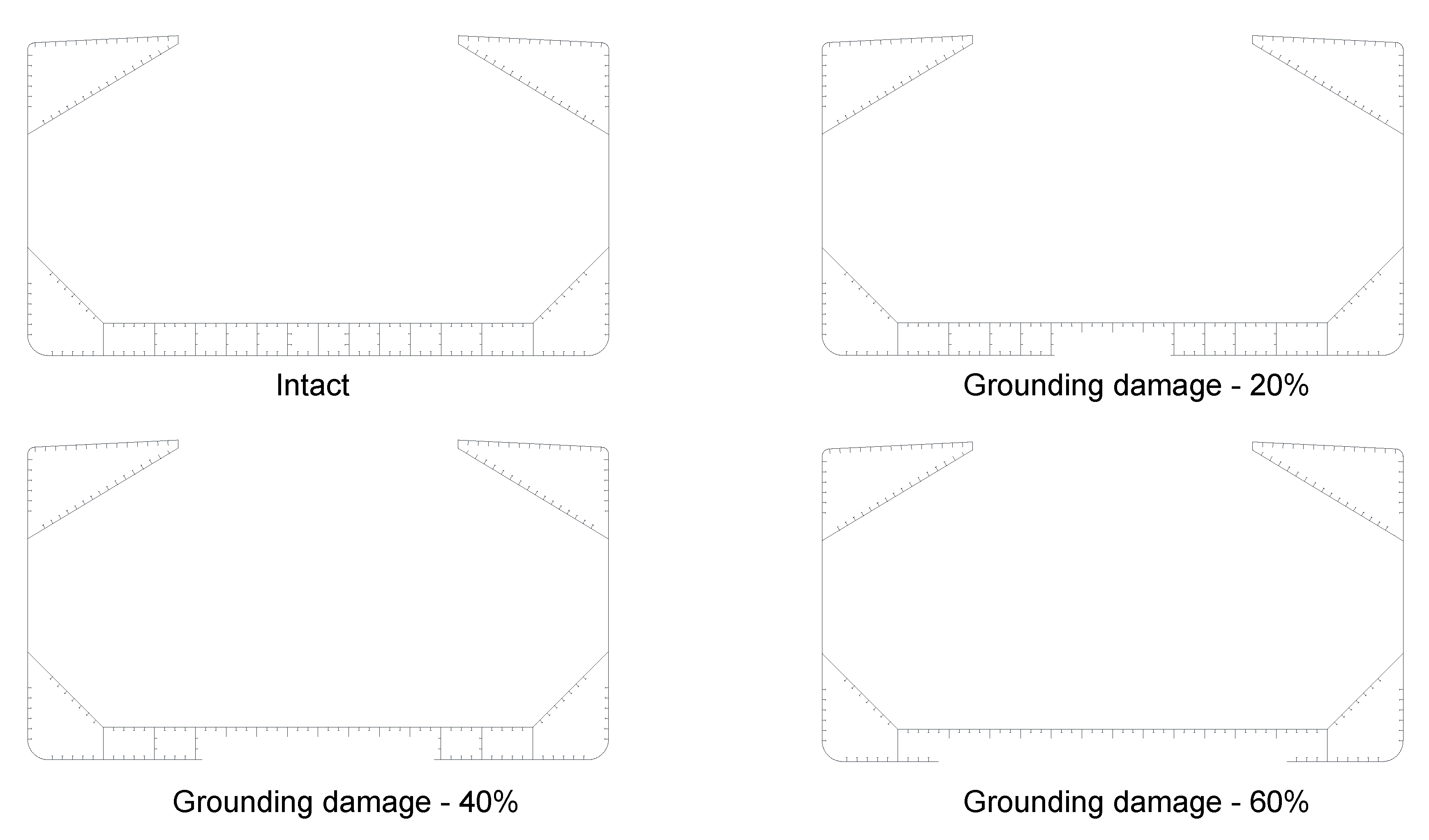
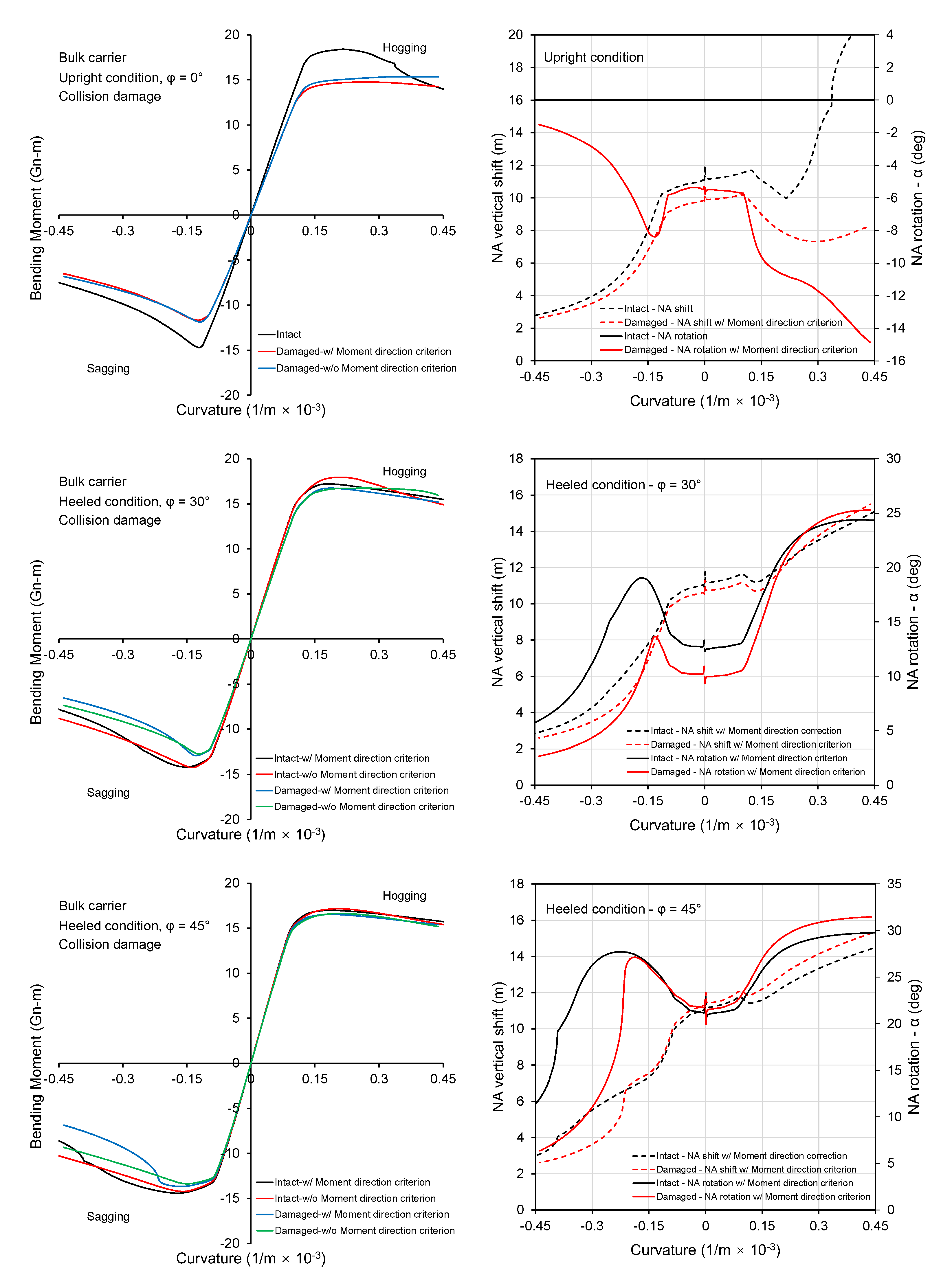
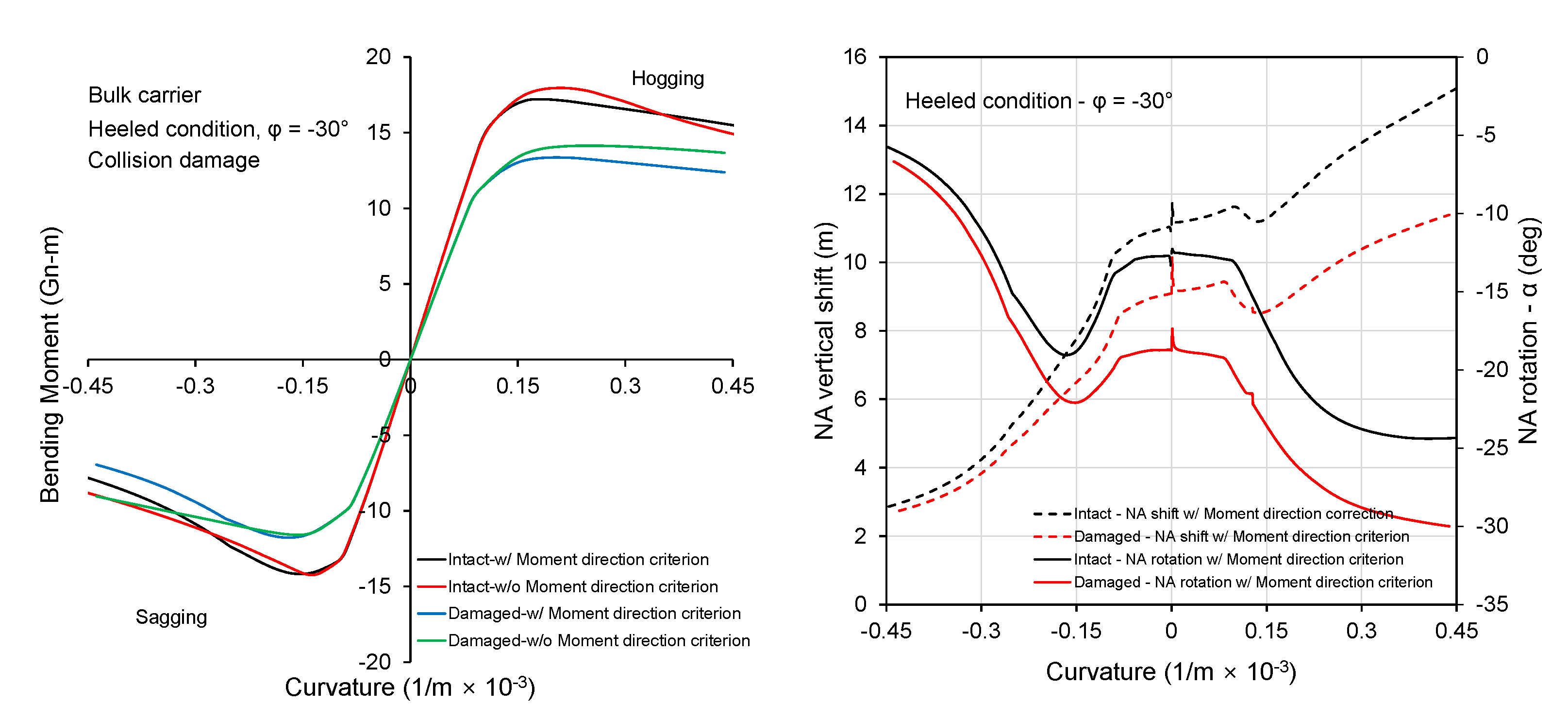
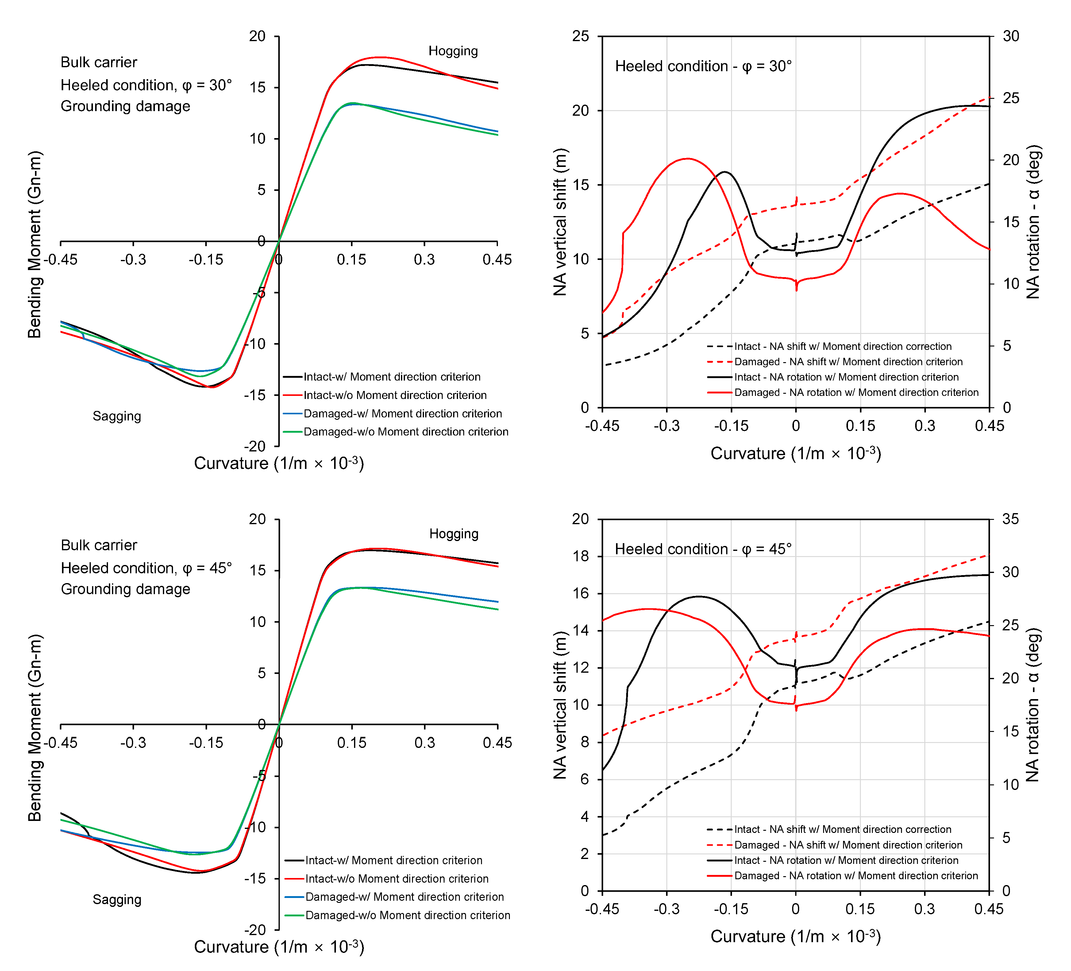
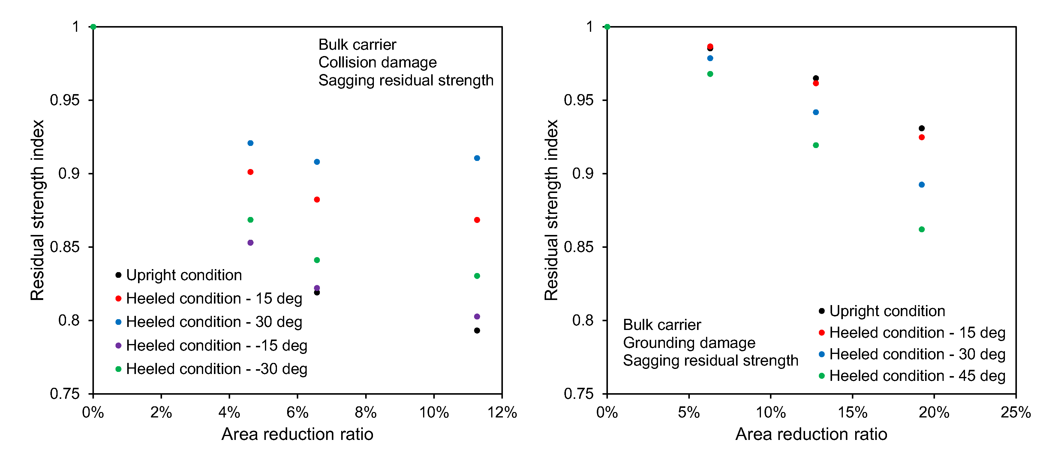
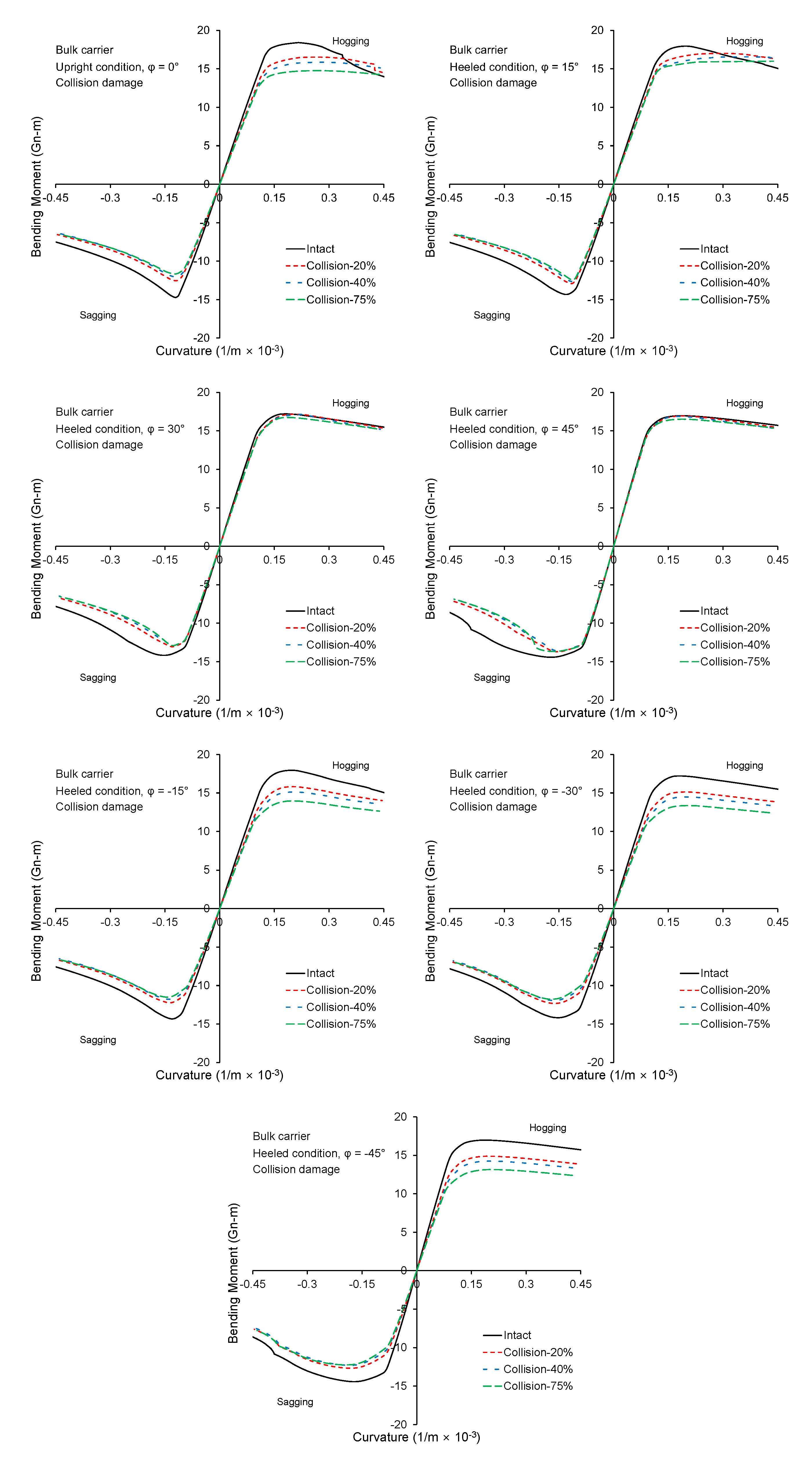
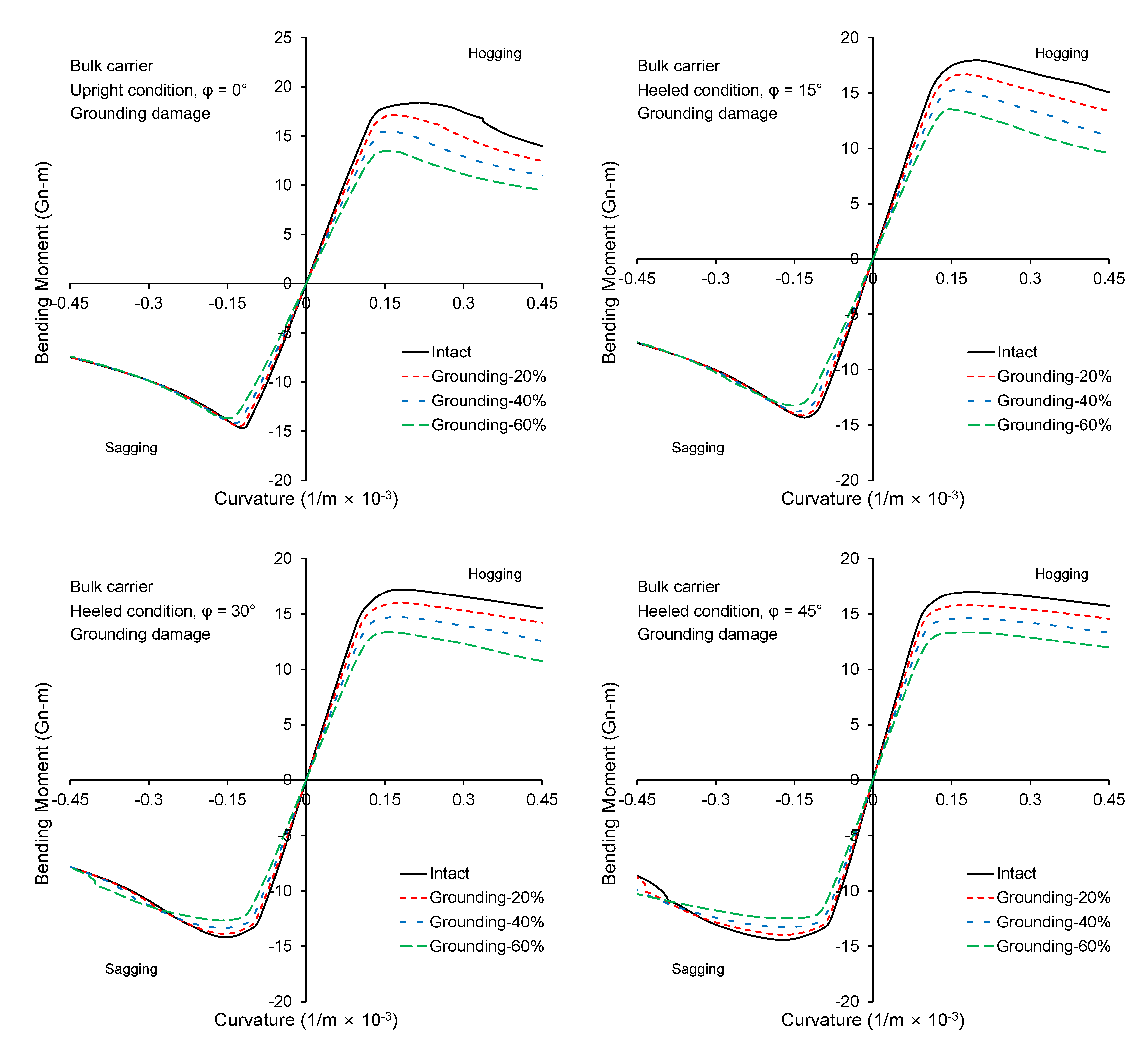
Figure 9 shows the moment–curvature curves obtained with the proposed procedure for collision damage ( 60 % ) and several different heeling angles. The right column presented the variation of neutral axis vertical position ( z ¯ C L ) and orientation ( α ) with applied curvature. In the moment–curvature curves, a comparison was made with the predictions obtained without applying the moment direction criterion given in Equation (22). If a moment direction criterion is not applied, the angle α is kept as its initial value, α 0 , and only a vertical shift is allowed to satisfy the zero net axial force condition. For the upright condition, it is evident that restraining NA rotation has a negligible effect in the post-collapse regime, even though a significant change in α is observed immediately after reaching ultimate strength. In other cases, NA rotates significantly in the post-ultimate strength regime. A marginal effect of the rotation of NA is evident for cases of a heeled condition with collision damage. Similarly, Figure 10 presents the moment–curvature curves and associated curves showing the shift and rotation of NA for the case of grounding damage. As shown in Figure 6, the assumed grounding damage is symmetrical. Therefore, an unsymmetrical loading is only the result of heeling. In such a case, the restraining rotation of NA has a negligible influence even in the post-collapse regime.
Figure 11 presents the residual strength index versus mid-ship cross-section area reduction ratio due to structural damage for the case of sagging. For each heeling angle, the residual strength index is defined as the ratio of ultimate strength in damaged condition over the intact ultimate strength. Figure A1 and Figure A2 shows the complete moment–curvature curves for all analyzed cases, from which the ultimate strength reduction due to collision and grounding damage can be assessed. The strength reduction due to collision damage, i.e., damage in the side shell and partially in the deck, is almost linearly proportional to the area reduction ratio. The cases of the heeled condition with positive loading plane direction and 60% damage are exceptional, but for these cases, the effect of the damage size is more evident in the post-collapse regime rather than the peak point in the moment–curvature curve. A strength reduction of approximately 20% was observed for the damage size defined in IACS-CSR for the upright and heeled conditions with negative angles. The strength reduction due to grounding damage depends more on the heeling angle. At larger heeling angles, the residual strength index decreases more with increasing area reduction ratio.

3.2. Bulk Carrier

Figure 12 highlights the effects of neutral axis rotation for the case of a bulk carrier with collision damage. Compared to the double hull VLCC, more apparent differences were observed between the moment–curvature curves obtained with and without applying the moment direction criterion. The curves diverge when the structural response becomes non-linear, and large differences are observed in the post-collapse response, even for an intact hull in a heeled condition. Generally, the extent of variation of α in the post-collapse regime is larger than the case of double hull VLCC. This is because once buckling or yielding occurs in the top and bottom flanges of the mid-ship section, the side and deck structures of a bulk carrier, where a double hull is absent and a top side tank is present, are unable to compensate for the moment direction criterion as the double hull and deck of the VLCC. Figure 13 makes a similar comparison for the case of grounding damage. Again, the effects of NA rotation are deemed to be significant as the structural response becomes non-linear.
Figure 14 presents the strength reduction due to a loss of cross-sectional area loss for the case of collision and grounding damage and sagging condition. Figure A3 and Figure A4 present the complete moment–curvature curves. In the case of a bulk carrier, the heeling angle significantly influences the rate of strength reduction with increasing loss of cross-sectional area due to collision damage. The trends for the grounding damage are similar to those observed in the case of a double hull VLCC.

3.3. Discussions

The findings of the present study were compared with previous research on the effect of a rotation of NA. Fujikubo et al. [5] assessed the effect of rotation of NA by comparing a case where only the vertical curvature is increased and horizontal curvature was constrained (constrained vertical bending) with a case with no constraint on the horizontal curvature (pure vertical bending). In the first case, the initial angle of NA was zero and was not allowed to change. This comparison is different from the one presented in the current work, where the initial angle of NA was calculated in advance for both cases of analysis with and without moment direction criterion. Considerable differences were observed between the two cases reported by Fujikubo et al. [5], not only in the post-collapse regime but also for the ultimate strength values. With regard to the descriptions given and findings presented in the current study, care must be taken when referring to the influence of rotation of NA. From the descriptions given in the sub-section of the elastic response under unsymmetrical bending, it is apparent that a damaged mid-ship section subjected to pure vertical bending will not result in an initial angle of NA, α 0 , that is equal to zero. Nevertheless, the overall findings of Fujikubo et al. [5] are similar to those obtained in the present study. The influence of NA rotation has less importance for the case of an oil tanker but has considerable influence for the bulk carriers and leads to a relatively more rapid loss of strength after reaching the collapse load.
Tekgoz et al. [19] presented a similar study but on a container ship. They reported that the rotation of NA has a larger influence on the progressive collapse behavior of container ships under hogging and the degree of influence depends on the heeling angle. Based on the current findings, these observations on container ships are relevant to ships with an open deck and double hull side construction. General conclusions regarding the effects of side damage on strength reduction, however, are similar to those drawn in the present study.

4. Conclusions

An extended progressive collapse analysis method for considering unsymmetrical loading on a ship hull girder was presented and applied to analyze a double hull VLCC and a bulk carrier. Based on the results obtained, the following conclusions can be drawn.
  • The moment direction criterion can be implemented in the analysis procedure of Smith’s method by adopting a nested iteration algorithm when determining the INA position. A quasi-Newton-Raphson method is appropriate for solving the iterative part of the progressive collapse analysis, yielding a fast and robust solution.
  • The influence of rotation of NA on the structural response is particularly important for the post-collapse regime. The relative importance of this phenomenon depends strongly on the structural configuration of the ship, loading condition (heeling angle), and damage location among others. A double hull VLCC showed less sensitivity to the inclusion of moment direction criterion compared to the bulk carrier.
  • The reduced strength of a bulk carrier caused by collision and grounding damage is sensitive to the heeling angle. This was attributed to side and deck structure construction type.
  • Overall, the proposed methodology, which adopts the moment direction criterion of a ship hull girder, can address the particular differences observed for each structural response of a ship under unsymmetrical loading.

Author Contributions

Conceptualization, J.C.; methodology, J.C. and B.C.C.; software, B.C.C.; validation, J.C. and B.C.C.; formal analysis, J.C. and B.C.C.; investigation, J.C. and B.C.C.; resources, J.C.; data curation, B.C.; writing—original draft preparation, B.C.; writing—review and editing, J.C. and B.C.C.; visualization, B.C.; supervision, J.C.; project administration, J.C.; funding acquisition, J.C. All authors have read and agreed to the published version of the manuscript.

Funding

This work was supported by the Korea Research Fellowship Program through the National Research Foundation of Korea (NRF) funded by the Ministry of Science and ICT (2017H1D3A1A01055137), and by industrial material core technology program “Development of steel application technologies against ice-induced crashworthiness and arctic temperature high toughness” funded by MOTIE/KEIT.

Conflicts of Interest

The authors declare no conflict of interest. The funders had no role in the design of the study; in the collection, analyses, or interpretation of data; in the writing of the manuscript, or in the decision to publish the results.

Abbreviations

The following abbreviations are used in this manuscript:
BLBaseline
CLCenterline
CSRCommon Structural Rules
IACSInternational Association of Classification Societies
INAInstantaneous neutral axis
NANeutral axis
VLCCVery large crude carrier

Appendix A

For the sake of completeness, the moment–curvature curves for all analysed cases are provided here in this appendix.
Figure A1. Moment–curvature curves for the case of double hull VLCC with collision damage.
Jmse 08 00988 g0a1
Figure A2. Moment–curvature curves for the case of double hull VLCC with grounding damage.
Jmse 08 00988 g0a2
Figure A3. Moment–curvature curves for the case of bulk carrier with collision damage.
Jmse 08 00988 g0a3
Figure A4. Moment–curvature curves for the case of bulk carrier with grounding damage.
Jmse 08 00988 g0a4

References

  1. Smith, C.S. Influence of local compressive failure on ultimate longitudinal strength of a ship’s hull. In Proceedings of the International Symposium on Practical Design in Shipbuilding, Tokyo, Japan, 18–20 October 1977; pp. 73–79. [Google Scholar]
  2. Dow, R.S.; Hugill, R.C.; Clark, J.D.; Smith, C.S. Evaluation of ultimate ship hull strength. In Proceedings of the Extreme Loads Response Symposium, Arlington, VA, USA, 19–20 October 1981; pp. 133–148. [Google Scholar]
  3. Smith, C.S. Structural redundancy and damage tolerance in relation to ultimate ship hull strength. In Proceedings of the International Symposium on Role of Design, Inspection and Redundancy in Marine Structural Reliability, Williamsburg, VA, USA, 14–16 November 1983; pp. 133–148. [Google Scholar]
  4. Smith, M.J.; Pegg, N.G. Automated assessment of ultimate hull girder strength. J. Offshore Mech. Arct. Eng. 2003, 125, 211–218. [Google Scholar] [CrossRef]
  5. Fujikubo, M.; Zubair Muis Alie, M.; Takemura, K.; Iijima, K.; Oka, S. Residual hull girder strength of asymmetrically damaged ships. J. Jpn. Soc. Nav. Archit. Ocean Eng. 2012, 16, 131–140. [Google Scholar] [CrossRef] [Green Version]
  6. IACS. Common Structural Rules for Bulk Carriers and Oil Tankers; International Association of Classification Societies: London, UK, 2020. [Google Scholar]
  7. Gordo, J.M.; Guedes Soares, C. Approximate method to evaluate the hull girder collapse strength. Mar. Struct. 1996, 9, 449–470. [Google Scholar] [CrossRef]
  8. Gordo, J.M.; Guedes Soares, C. Interaction equation for the collapse of tankers and containerships under combined bending moments. J. Ship Res. 1997, 41, 230–240. [Google Scholar]
  9. Gordo, J.M.; Guedes Soares, C. Residual strength of damaged ship hulls. In Proceedings of the IX International Maritime Association of Mediterranean Congress (IMAM 2000), Ischia, Italy, 2–6 April 2000; pp. 79–86. [Google Scholar]
  10. Fang, C.; Das, P.K. Survivability and reliability of damaged ships after collision and grounding. Ocean Eng. 2005, 32, 293–307. [Google Scholar] [CrossRef]
  11. Khan, I.A.; Das, P.K. Reliability analysis of intact and damaged ships considering combined vertical and horizontal bending moments. Ships Offshore Struct. 2008, 3, 371–384. [Google Scholar] [CrossRef]
  12. Guedes Soares, C.; Luís, R.M.; Nikolov, P.; Downes, J.; Taczala, M.; Modiga, M.; Quesnel, T.; Toderan, C.; Samuelides, M. Benchmark study on the use of simplified structural codes to predict the ultimate strength of a damaged ship hull. Int. Shipbuild. Prog. 2008, 55, 87–107. [Google Scholar] [CrossRef]
  13. Hussein, A.; Guedes Soares, C. Reliability and residual strength of double hull tankers designed according to the new IACS common structural rules. Ocean Eng. 2009, 36, 1446–1459. [Google Scholar] [CrossRef]
  14. Luís, R.; Teixeira, A.; Guedes Soares, C. Longitudinal strength reliability of a tanker hull accidentally grounded. Struct. Saf. 2009, 31, 224–233. [Google Scholar] [CrossRef]
  15. Choung, J.; Nam, J.M.; Ha, T.B. Assessment of residual ultimate strength of an asymmetrically damaged tanker considering rotational and translational shifts of neutral axis plane. Mar. Struct. 2012, 25, 71–84. [Google Scholar] [CrossRef]
  16. Choung, J.; Nam, J.M.; Tayyar, G.T. Residual ultimate strength of a very large crude carrier considering probabilistic damage extents. Int. J. Nav. Archit. Ocean Eng. 2014, 6, 14–26. [Google Scholar] [CrossRef] [Green Version]
  17. Campanile, A.; Piscopo, V.; Scamardella, A. Statistical properties of bulk carrier residual strength. Ocean Eng. 2015, 106, 47–67. [Google Scholar] [CrossRef]
  18. Campanile, A.; Piscopo, V.; Scamardella, A. Comparative analysis among deterministic and stochastic collision damage models for oil tanker and bulk carrier reliability. Int. J. Nav. Archit. Ocean. Eng. 2018, 10, 21–36. [Google Scholar] [CrossRef]
  19. Tekgoz, M.; Garbatov, Y.; Guedes Soares, C. Strength assessment of an intact and damaged container ship subjected to asymmetrical bending loadings. Mar. Struct. 2018, 58, 172–198. [Google Scholar] [CrossRef]
  20. Zhu, Z.; Ren, H.; Li, C.; Zhou, X. Ultimate limit state function and its fitting method of damaged ship under combined loads. J. Mar. Sci. Eng. 2020, 8, 117. [Google Scholar] [CrossRef] [Green Version]
  21. Makouei, S.H.; Teixeira, A.P.; Guedes Soares, C. A study on the progressive collapse behavior of a damaged hull girder. In Maritime Technology and Engineering; Guedes Soares, C., Santos, T.A., Eds.; CRC Press: Boca Raton, FL, USA, 2015; pp. 405–416. [Google Scholar]
  22. Kuznecovs, A.; Ringsberg, J.W.; Johnson, E.; Yamada, Y. Ultimate limit state analysis of a double-hull tanker subjected to biaxial bending in intact and collision-damaged conditions. Ocean Eng. 2020, 209, 107519. [Google Scholar] [CrossRef]
  23. Parunov, J.; Rudan, S.; Bužančić Primorac, B. Residual ultimate strength assessment of double hull oil tanker after collision. Eng. Struct. 2017, 148, 704–717. [Google Scholar] [CrossRef]
  24. Nielsen, L. Structural Capacity of the Hull Girder. Ph.D. Thesis, Technical University of Denmark, Lyngby, Denmark, 1998. [Google Scholar]
  25. Yao, T.; Astrup, O.; Caridis, P.; Chen, Y.N.; Cho, S.R.; Dow, R.S.; Niho, O.; Rigo, P. Report of Special Task Committee VI.2 Ultimate Hull Girder Strength. In Proceedings of the 14th International Ship and Offshore Structures Congress (ISSC 2000), Nagasaki, Japan, 2–6 October 2000; pp. 321–397. [Google Scholar]
  26. Paik, J.K.; Amlashi, H.; Boon, B.; Branner, K.; Caridis, P.; Das, P.; Fujikubo, M.; Huang, C.H.; Josefson, L.; Kaeding, P.; et al. Report of Committee III.1 Ultimate Strength. In Proceedings of the 18th International Ship and Offshore Structures Congress (ISSC 2012), Rostock, Germany, 10–13 September 2012; pp. 285–363. [Google Scholar]
  27. Cerik, B.C.; Ringsberg, J.W.; Choung, J. Revisiting MARSTRUCT benchmark study on side-shell collision with a combined localized necking and stress-state dependent ductile fracture model. Ocean Eng. 2019, 187, 106173. [Google Scholar] [CrossRef]
  28. Cerik, B.C.; Lee, K.; Park, S.J.; Choung, J. Simulation of ship collision and grounding damage using Hosford-Coulomb fracture model for shell elements. Ocean Eng. 2019, 173, 415–432. [Google Scholar] [CrossRef]
  29. Cerik, B.C.; Park, S.J.; Choung, J. Use of localized necking and fracture as a failure criterion in ship collision analysis. Mar. Struct. 2020, 73, 102787. [Google Scholar] [CrossRef]
  30. Cerik, B.C.; Choung, J. Rate-dependent combined necking and fracture model for predicting ductile fracture with shell elements at high strain rates. Int. J. Impact Eng. 2020, 146, 103697. [Google Scholar] [CrossRef]
  31. Cerik, B.C. Ultimate longitudinal compressive strength of steel plates with lateral patch load induced plastic deformation. Thin-Walled Struct. 2018, 122, 416–424. [Google Scholar] [CrossRef]
Figure 1. Unsymmetrical bending of ship hull girder: (a) Intact ship in heeled condition. (b) Damaged ship in upright condition. (c) Damaged ship in heeled condition.
Jmse 08 00988 g001
Figure 2. Coordinate system adopted in the progressive collapse analysis for unsymmetrical bending.
Jmse 08 00988 g002
Figure 3. Centroids of resultant forces and an explanation of the condition for the direction of bending moment.
Jmse 08 00988 g003
Figure 4. Flowchart of the proposed extension of the incremental-iterative method.
Jmse 08 00988 g004
Figure 5. Assumed collision damage extents in double hull VLCC.
Jmse 08 00988 g005
Figure 6. Assumed grounding damage extents in double hull VLCC.
Jmse 08 00988 g006
Figure 7. Assumed collision damage extents in bulk carrier.
Jmse 08 00988 g007
Figure 8. Assumed grounding damage extents in bulk carrier.
Jmse 08 00988 g008
Figure 9. Moment–curvature curves and neutral axis shift and translation for the case of double hull VLCC with collision damage.
Jmse 08 00988 g009
Figure 10. Moment–curvature curves and neutral axis shift and translation for the case of double hull VLCC with grounding damage.
Jmse 08 00988 g010
Figure 11. Residual strength index vs. area reduction ratio for the case of double hull VLCC.
Jmse 08 00988 g011
Figure 12. Moment–curvature curves and neutral axis shift and translation for the case of bulk carrier with collision damage.
Jmse 08 00988 g012aJmse 08 00988 g012b
Figure 13. Moment–curvature curves and neutral axis shift and translation for the case of bulk carrier with grounding damage.
Jmse 08 00988 g013
Figure 14. Residual strength index vs. area reduction ratio for the case of bulk carrier.
Jmse 08 00988 g014
Table 1. Main particulars of target ships.
ParticularDouble Hull VLCCBulk Carrier
Length (m)315285
Breadth (m)5850
Depth (m)30.326.7
Block coefficient0.820.83
Publisher’s Note: MDPI stays neutral with regard to jurisdictional claims in published maps and institutional affiliations.

