Article

Sensitivity and Directivity Analysis of Piezoelectric Ultrasonic Cantilever-Based MEMS Hydrophone for Underwater Applications

by
Basit Abdul
1,2,*,
Vincenzo Mariano Mastronardi
1,
Antonio Qualtieri
1,
Luciana Algieri
1,
Francesco Guido
1,
Francesco Rizzi
1,* and
Massimo De Vittorio
1,2
1
Center for Biomolecular Nanotechnologies, Istituto Italiano di Tecnologia, Via Barsanti 14, 73010 Arnesano (Lecce), Italy
2
Department of Innovation Engineering, University of Salento, Via per Monteroni, 73100 Lecce, Italy
*
Authors to whom correspondence should be addressed.
J. Mar. Sci. Eng. 2020, 8(10), 784; https://doi.org/10.3390/jmse8100784
Submission received: 10 September 2020 / Revised: 30 September 2020 / Accepted: 2 October 2020 / Published: 9 October 2020
(This article belongs to the Special Issue Advanced Instruments for Marine Research)

Abstract

:
In this paper, we report on the characterization of the sensitivity and the directionality of a novel ultrasonic hydrophone fabricated by micro-electro-mechanical systems (MEMS) process, using aluminum nitride (AlN) thin film as piezoelectric functional layer and exploiting a stress-driven design. Hydrophone structure and fabrication consist of four piezoelectric cantilevers in cross configuration, whose first resonant frequency mode in water is designed between 20 kHz and 200 kHz. The MEMS fabricated structures exploit 1 µm and 2 µm thick piezoelectric AlN thin film embedded between two molybdenum electrodes grown by DC magnetron sputtering on silicon (Si) wafer. The 200 nm thick molybdenum electrodes thin layers add a stress-gradient through cantilever thickness, leading to an out-of-plane cantilever bending. A water resistant parylene conformal coating of 1 µm was deposited on each cantilever for waterproof operation. AlN upward bent cantilevers show maximum sensitivity up to −163 dB. The cross configuration of four stress-driven piezoelectric cantilevers, combined with an opportune algorithm for processing all data sensors, permits a finer directionality response of this hydrophone.

1. Introduction

Hydrophones are underwater acoustic receivers that play an increasingly important role in submarine resources exploration, marine military, underwater noise monitoring, and sonar systems [1]. Hydrophone design and fabrication are based on micro-electro-mechanical systems (MEMS) technology, combining solid-state physics, mechanics, acoustics, and electronics [2] to detect underwater sounds. A piezoelectric-based MEMS hydrophone is an electroacoustic transducer converting mechanical excitation due to acoustic pressure into electrical signal. Usually, the readout mechanism of micro-electro-mechanical system (MEMS) devices exploits piezoelectric or piezoresistive material as sensing element [3,4,5]. MEMS-based hydrophones have been demonstrated to be able to trace the exact location as well as direction of underwater sound sources [6]. In 1996, a MEMS-based hydrophone was reported as the first directional underwater acoustic sensor [7]. Since then, MEMS ultrasonic transducers, in which thin film of piezoelectric material is used as sensing elements, have been widely studied and used for numerous underwater applications [8,9]. A bio mimetic approach has been successfully pursued to design cantilever and membrane base hydrophone. Two T-shape vector hydrophone using MEMS technology inspired by fish lateral line, based on piezoresistive cantilever has been reported [10]. These hydrophones have receiving sensitivity up to −180 dB and −192 dB at 1 kHz, showing directivity pattern in the form of dipolar “8” shape. Moreover, hydrophones based on a structure in which liquid is used to bridge the gap between a piezoresistive cantilever and the surrounding walls, have been reported [11,12]. Experimental results proved that hydrophones have the capability of measuring acoustic frequency in underwater between 100 Hz to 8 kHz. Finally, a micro-machined hydrophone based on piezoelectric PZT membrane was developed [13], and in order to improve the sensitivity, air backing was implemented.
In the last few years, piezoelectric micro machined sensors have shown tremendous progress [14,15,16,17,18]. Aluminum nitride (AlN) based MEMS devices, such as microphones [19], piezoelectric micro machined ultrasonic transducers (pMUTs) [20,21,22], inertial sensors [23,24,25], and RF resonator devices, [26,27,28] are recently attracting more and more attention because of excellent characteristics in terms of AlN compatibility with CMOS fabrication process, biocompatibility, and low power operation. In spite of the low piezoelectric coefficient [29], the small dielectric constant of AlN [30] makes it very attractive for piezoelectric MEMS transducers.
Hydrophones based on piezoelectricity show high directionality performances at desired ultrasonic range [31,32,33,34,35] but the physical dimensions of their conventional design have some limitations in sonar systems due to their large size [36,37,38]; therefore, importance has been given on the miniaturization of hydrophones in recent years [39,40]. They show some additional advantages such as robustness, high sensitivity, low cost, and mass production possibility. Small MEMS hydrophones have advantage of precise measurements because these are less prone to the effects of acoustic diffraction [36,41]. Recently, in order to improve hydrophone directionality detection, piezoelectric cantilevers have been introduced in underwater acoustic sensing [42]. In particular, additional layers to the cantilever structural layer by appropriate thin film growth technologies generates a controllable stress gradient across the layered cantilever, allowing a stress-driven “out-of-plane” bending [43]. In fact, the stress gradient can cause deformation once released in suspended microstructure. This makes possible to realize mechanical structures sensitive to underwater acoustic sound. In particular, nitride-based materials (such as aluminum nitride), because of the material stress differences among the cantilever constituent layers, can be exploited for fabricating bent cantilever.
These micro-mechanical structures are more prone to be deformed by external mechanical excitations [44,45,46,47], resulting in the improvement of directionality detection and consequent ability to find acoustic sources. In fact, out-of-plane bent cantilevers in particular can be exploited as fundament building block for a directional hydrophone. A suitable cantilevers’ array configuration allows, through signal combination from all single cantilevers, to obtain directional response [48,49,50]. In particular, a cross shape configuration of four bent cantilevers with an appropriate signal treatment algorithm produces a directivity pattern allowing to easily refine the directionality of incoming underwater sounds. Novel and finer directivity pattern allows the development of new data acquisition systems to obtain long-term and dynamic information on sound producing marine organisms. Among the marine organisms, dolphins and whales emit short ultrasonic pulses to acquire information about the surrounding environment, prey, and habitat features. Recording, studying, and processing of acoustic datasets are essential tools needed to advance ability to follow dolphins path in the wild marine environment [51].
In this work, a hydrophone based on the cross configuration of four out-of-plane bent piezoelectric MEMS cantilevers was designed, fabricated, and exploited as directional acoustics receiver. Simulations were performed using finite element methods (FEM) to study their resonant behavior. The cross configuration provides directional response in order to find out the acoustics source direction in water. In this work, a novel algorithm is applied to the first directional hydrophone based on piezoelectric cantilever for underwater ultrasonic communications in a frequency range from 20 kHz up to 200 kHz, showing a low uncertainty in incoming directions detection.
This work is divided in three sections. First, the design and analysis of the micro cantilevers model by FEM is reported; second, the MEMS fabrication process is described; and finally, the sensitivity and directionality of the hydrophone is characterized.

2. Materials and Methods

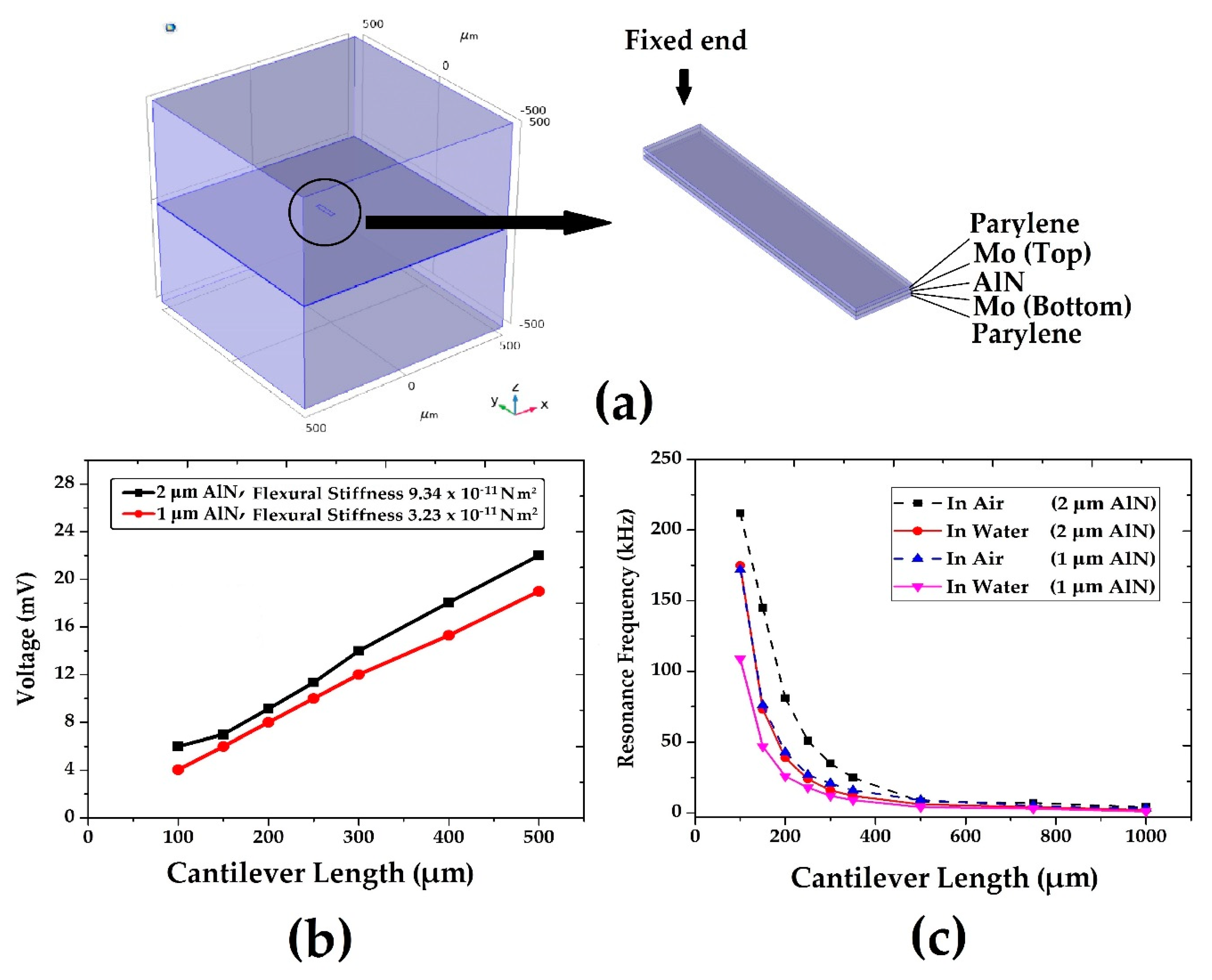
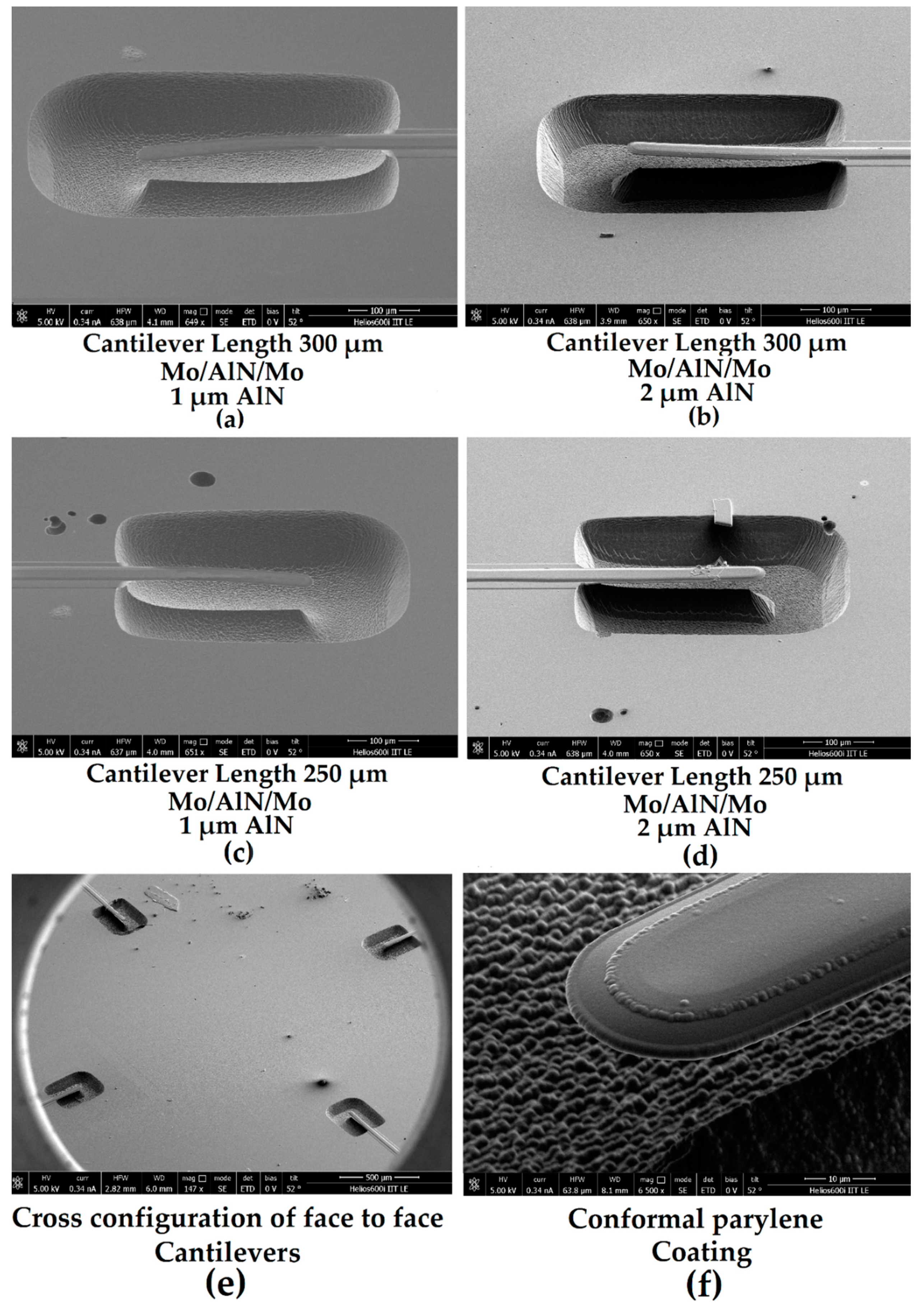
Device Design and Fabrication

Piezoelectricity is a coupling mechanism relating the mechanical and electrical properties of a material. An electrical charge is produced when the piezoelectric material is mechanically deformed and vice versa. The piezoelectric constitutive equations, also known as “coupled equations” are given below [52] in the stress-charge form:
T = sE SeT E
D = e S + ε E
where S is the strain tensor, sE is the elasticity matrix, T is the stress tensor, e is piezoelectric coupling matrix, D is the tensor of electric displacement, ε is the electrical permittivity, and E is the electric field.
In order to explore nitride-based MEMS directional hydrophones and to maximize the receiving sensitivity over the desired frequency range, a stress-driven structure of the device was designed and simulated by using the finite element method (COMSOL Multiphysics). For designing the transducer, acoustics-structure interaction and piezoelectric effect was simulated in water environment (see Figure 1a). The cantilever was fixed at one end while all the other faces were unconstrained, allowing the bending of the device. The mesh was composed of 202,168 elements, using free quad and free tetrahedral finite elements. Two different structures have been simulated, exploiting a piezoelectric aluminum nitride (AlN) functional layer of 1 µm and 2 µm thickness, having two flexural stiffnesses of approximately 3 × 10⁻¹¹ N m2 and 9 × 10⁻¹¹ N m2, respectively. Higher AlN thickness provides higher flexural stiffness making the cantilever less responsive and brittle. The following piezoelectric coefficient for AlN has been used: e13 = −0.58 C m−2 and e33 = 1.55 C m−2 [53], where 200 nm thick top and bottom molybdenum (Mo) electrodes were implemented. Finally, in order to avoid short circuits in water, a parylene conformal coating of 1 µm thickness was applied. Table 1 shows the mechanical properties of materials and their thicknesses, used to design and simulate the micro cantilever’s response.
In a first set of simulations, different lengths of cantilevers, ranging between 100 µm to 500 µm and a constant width of each cantilever equal to 70 µm, have been investigated. Out of plane upward curvature was fixed at 5 × 10⁻⁴ µm−1 (one of the curvature values experimentally found) for both cantilevers and a constant acoustics force per surface unit equals to 5 kN/m2 was applied. FEM simulations in Figure 1b demonstrate two different fluid structure interaction mechanisms: for a fixed upward curvature at a constant acoustic intensity, there is an increase of signal with length while higher signals are generated by increasing the flexural stiffness of the cantilever. In fact, in “out-of-plane” bent piezoelectric cantilevers, the signal is strongly dependent on the geometrical features of the beam. The acoustic wave perturbation in the water, distributing its drag force on the whole beam surface, is intense enough to further bend the cantilever and generate a signal from the sound traveling through water. At the same acoustic intensity, the drag force acting on each sensor is directly dependent from the apparent cantilever area (e.g., by increasing the length), as a consequence [44]. A further control in the hydrophone response to the acoustic excitation can be introduced by changing the flexural stiffness of the cantilever-based hydrophone, achieved by exploiting different layer thicknesses. Provided the same apparent cantilever area and a fixed mechanical excitation, thinner cantilever distributes the acoustic deformation all along the cantilever beam, experiencing a lower stress on the hinge with a consequent lower piezoelectric signal. In contrast, thicker cantilevers will experience a higher external mechanical stress localized at the hinge; therefore, a higher piezoelectric voltage and a better sensitivity is obtained. Both mechanisms are observed experimentally.
The designed 3-D model of micro cantilevers with different lengths (between 100 µm to 1000 µm) have been analyzed using the eigenfrequency study to set the first resonant frequency mode in water between 20 kHz to 200 kHz, the desired acoustic range of the device (Figure 1c). As expected, Figure 1c shows that the first resonance frequency of micro cantilevers decreases as their length increases. It is noteworthy, due to damping effect, that the first resonance mode of frequency of each micro cantilever in water decreases as compared to that in air for both thicknesses [54]. Both cantilevers resonances fall in the ultrasonic frequency range.
These cantilevers were fabricated by a standard MEMS process, previously applied to the piezoelectric aluminum nitride-based design grown on a silicon substrate [44]. A thin layer of molybdenum (200 nm) was deposited by DC magnetron sputtering. Mask aligner (SUSS MA8/BA8) exposure was used after spin coating of AZ5214E photoresist with 2 μm thickness for bottom electrode definition (Figure 2a). Then, aluminum nitride (1 µm and 2 µm) and molybdenum (200 nm) were deposited by DC magnetron sputtering. TI35E photoresist with thickness of 4 μm was spin coated for piezoelectric functional layer and top electrode definition (Figure 2b). MIF AZ826 was applied for development of all photoresists. Inductively coupled plasma (ICP) etching with Boron Trichloride (BCl3, 45 sccm) and Nitrogen (N2, 20 sccm) for Mo layer, while Boron Trichloride (BCl3, 100 sccm) and Argon (Ar, 25 sccm) for AlN layer were used to remove exposed layer. Both recipes had RF powers applied to platen equals to 250 W and to coil equals to 600 W, respectively. For cantilever release, silicon etching was performed at 700 sscm of SF6, coil power of 2600 W and pressure of 100 mTorr at temperature 18 °C. Two possible curvatures (Figure 2c), upwards bending (tensile stress) or downwards bending (compressive stress), can be observed.

3. Results and Discussion

SEM images in Figure 3 show selected cantilevers with different lengths and bending, in dependence of increased thickness of AlN. Figure 3a,c shows cantilevers bending in downward direction (AlN thickness equals to 1 µm) while Figure 3b,d shows cantilevers with bending in upward direction (AlN thickness equals to 2 µm). This is in good agreement with Stoney equation for cantilever [44], where the curvature C is expressed:
C   =   1 R   =   6 δ E t 2
where R is radius of curvature t is the thickness of the cantilever, E is the Young modulus, and δ is the modulus of the surface stress. The intrinsic stress of AlN accumulated during the sputtering process and residual stress gradient inside the multilayer structure causes the bending in upward direction for 2 µm thick AlN, having an average tensile surface stress of 438 N/m. In contrast, 1 µm thick AlN cantilevers show a slightly downward direction due to compressive residual stress gradient with an average surface stress of 53 N/m [2]. This is explained because a change on AlN thickness leads to a shift in neutral axis position, due to a change in the whole beam stress due to different growth time and temperature. The mismatch of atomic sizes between different layered materials or lattice-mismatch developed in the thermal cycling of the chip during material deposition and micro-fabrication is the origin in the stress gradient [45]. If needed, a careful setup of growth conditions would allow to neutralize the bending or to place it out of the AlN thickness position in order to further bends the cantilevers and improve the device signals [2]. In Figure 3e, SEM image of face-to-face, cross-configuration of four cantilevers, having 300 µm length has been shown while Figure 3f shows tip of fabricated micro cantilever with conformal parylene coating.
Electrical characterization was realized by LCR meter (Keysight-E4980AL) at 1 kHz frequency and excitation amplitude of two volts, to measure the transducer capacitance as shown in Figure 4a. The capacitance of cantilevers increases with length and decreases with thickness of aluminum nitride, as expected by theory. Figure 4b shows laser doppler vibrometer (Polytec Vibrometer MSA500) measurements at five volts excitation for different cantilever lengths, ranging between 100 μm and 300 μm, with aluminum nitride thickness of 1 µm and 2 µm. The figure shows that the measured first resonance mode frequency is in agreement with the simulated frequency of the cantilevers. The deviation between simulations and measurements was present only for one length for the 2 µm thick aluminum nitride layer as shown in Figure 4b, most likely due to a small difference between the nominal geometrical dimensions and the fabrication results.

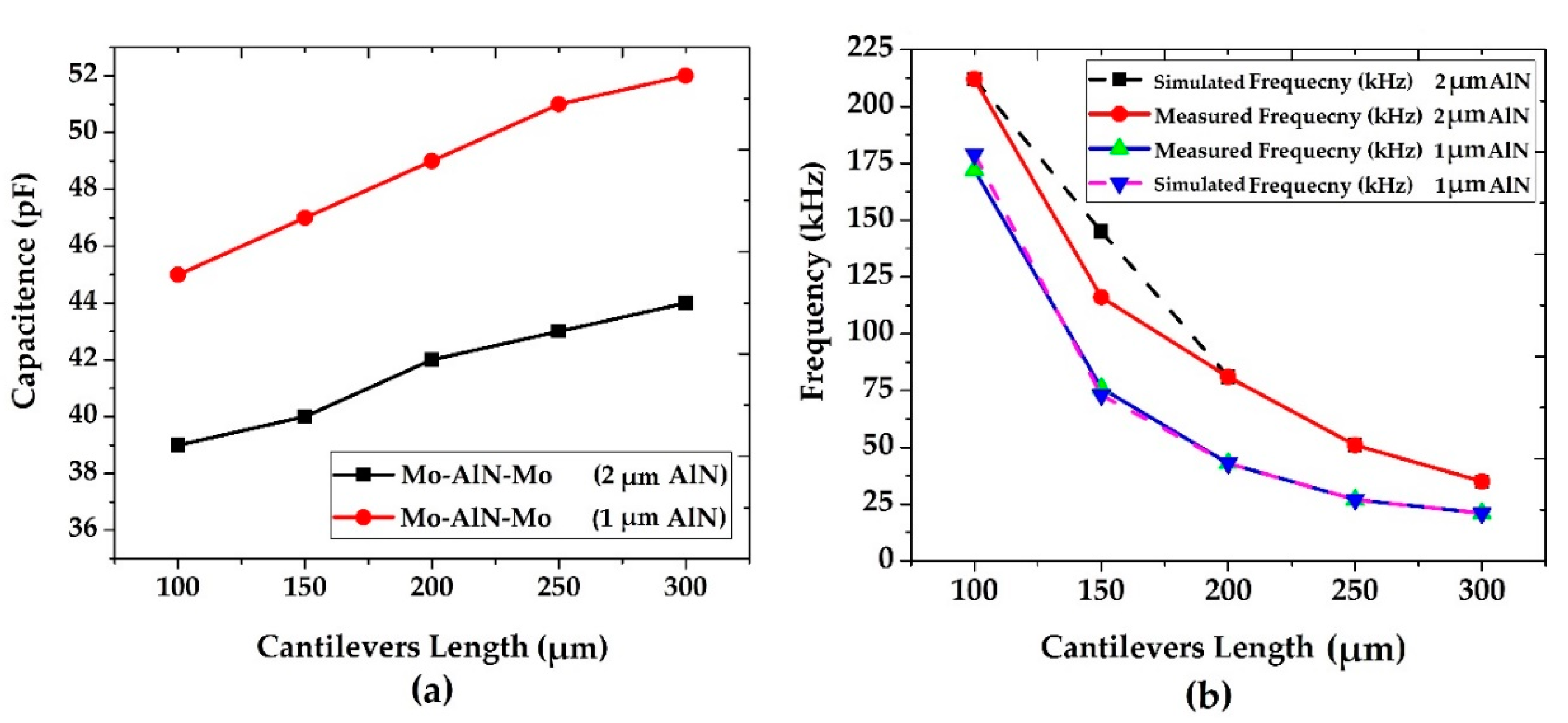
3.1. Underwater Characterization
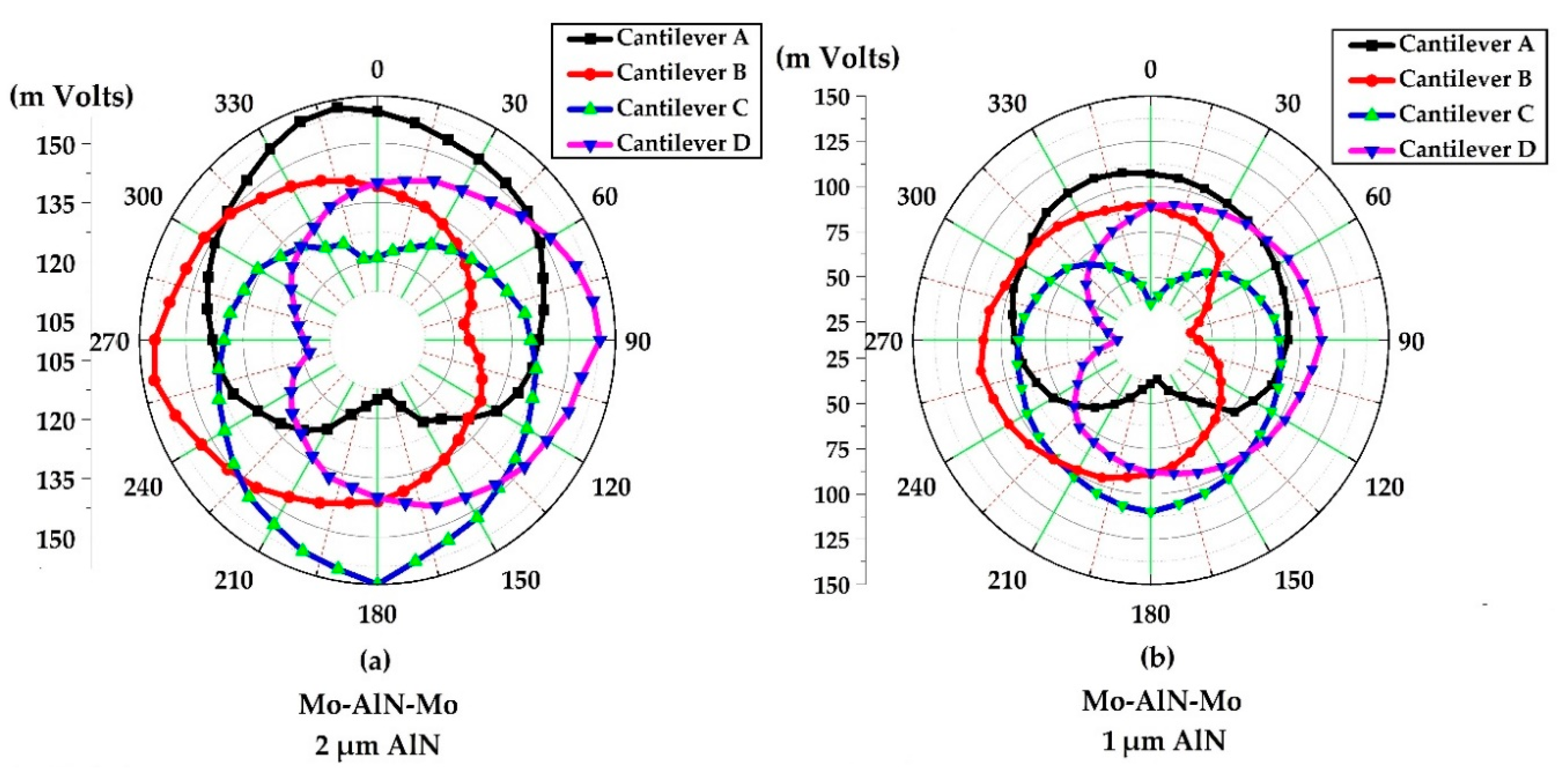
Characterization of hydrophone mostly refers to the sensitivity and directionality. Measurement set up was composed by of emission transducer (200 kHz), reference hydrophone (Onda HNP-1000), oscilloscope (Tektronix, MSO2000B), MEMS transducer, function generator (DPR 300, control with PC) and a rotary stage. A pulsed acoustic wave centered at 200 kHz was produced by an emission transducer driven by a pulse generator at 5 kHz pulse repetition frequency (PRF) and 475 volts as supply voltage to emission transducer. Measurements parameter for underwater characterization of hydrophone have been described deeply in the previous work [44]. Peak output voltages from each cantilever were measured by oscilloscope. It is clear from the Figure 5a that the average output signal response of each cantilever is increasing with length. The highest values of voltage response were achieved with a thickness of 2 µm of AlN. In fact, cantilevers having upward bending increases the acoustic-structure interaction super linearly.
Sensitivity measurements were performed by normalizing the signal response to a reference hydrophone with MEMS transducer. The sensitivity of the hydrophone is expressed [44,55] as
S M E M S = S r e f   V M E M S V r e f   s i n e k d c o s e   k d
where S M E M S is the sensitivity of the tested hydrophone and S r e f (−253 dB re. 1 V/µPa) [56] is the sensitivity of the reference hydrophone (HNP-1000 Broadband Needle Type and Hydrophone Preamplifier, 20 dB gain, Onda Corporation). V M E M S and V r e f are the peak voltage response from MEMS and reference hydrophone, respectively, k denotes the number of waves and d is the distance from surface of water to reference hydrophone and to the MEMS transducer under test. Figure 5b shows sensitivity measurements of MEMS fabricated hydrophone at 5 kHz PRF and 475 volts supply voltage. It shows that sensitivity increases with length of the cantilevers and, at the same length increases with thickness. Highest sensitivity up to −163 dB was achieved by Mo/AlN/Mo hydrophone with 300 µm length and 2 µm thick AlN functional layer upward cantilever.
Table 2 shows the comparison of MEMS hydrophone with other cantilever-based hydrophones based on different transduction mechanisms and including commercial ones. It shows that MEMS hydrophone has comparable sensitivity with other devices. Moreover, it has the advantage of miniaturization and due to cross-configuration; it presents directional response, which allows finding the acoustic source direction.

3.2. Directionality

MEMS hydrophone was located on a rotary stage and the directivity pattern of the MEMS hydrophone was measured by collecting the signal response for every 10° rotation angles with respect to acoustic source. In the present method, all cantilevers have been excited to operate in four main read-out modes: Cardioid, Omni, Dipole, and Quadrant mode.
Figure 6 shows directional cardioid shaped response from each single cantilever of the cross configurations. In details, Figure 6a,b show aluminum nitride based cantilevers (2 µm and 1 µm AlN thickness, respectively). The maximum cardioid response was measured for the upward bent cantilever, with 2 µm thick AlN (Figure 6a). Conversely, the 1 µm thick AlN (Figure 6b) shows a lower response because of slightly downward bending. Each single cantilever in cross configuration show directivity pattern with a sensing directionality aperture close to 160°. Figure 7 shows different Omni directivity pattern signal combinations for the two different cross-configurations, obtained by summing up all signal response of each cantilever. Through Omni directivity configuration, hydrophone can detect sounds uniformly in all the direction. By comparison between Figure 6 and Figure 7, cantilevers from a cross configuration made by upwards cantilevers and a thicker piezoelectric aluminum nitride layer have a higher voltage response and sensitivity, therefore being more sensitive to all the direction as compared to the cross configuration of thinner slightly downward cantilevers. From now on, alternative directionality patterns have been investigated exploiting the most sensitive cantilever cross configuration (i.e., 2 µm thick AlN).
Figure 8a,b shows a dipole beam pattern configuration, consisting of subtracting the sum of signals coming from facing cantilevers on one axis with the sum of cantilevers signals coming from the respective orthogonal axis, for the upward bent 2 μm thick aluminum nitride based cantilevers with length of 300 µm. We can define x-axis direction dipole and y-axis direction dipole by commuting the minuend and subtrahend. The regions, where the dipolar signals are positive, are approximately 40° wide along both x-axis and y-axis direction. The red circle defines the regions where the voltage signal changes between positive and negative value; for each dipole mode, only the positive signal will be exploited for discriminating directionality. Noteworthy, dipole directivity can discriminate axial directions but not the sound source side position (90° or 270° for x-axis in Figure 8a and 0° or 180° for y-axis in Figure 8b). Finally, quadrant modes (their mathematical expression are in each legend of Figure 8c–f) give a pattern with a positive signal in 90° wide aperture range placed in each quadrant (0° to 90°, 90° to 180°, 180° to 270°, and 270° to 360°, respectively, as shown in Figure 8c–f. Therefore, a directional quadrant mode needs to be defined for each quadrant.
Focusing on the direction ranges where signals are positive, a suitable combination of the two dipole and four quadrant configurations allows to easily refine the direction of incoming sounds. As an example, the contemporary combination of the positive range (from +50° to 140° and from 240° to 330°) of the dipolar configuration in Figure 8a with the maximum signal range (from 0° to 90°) of the configuration in Figure 8c gives the intersection range which allows to identify the direction of sound coming approximately between 50° and 90° with aperture close to 40°, as shown in Figure 9a. Similarly, if both dipole axis have a value in modulus very close to 0 mV, the quadrant, among the four different quadrant modes, giving the maximum positive value identifies the inter-cardinal direction the acoustic signal is coming from. In fact, as a further example, the combination of a zero signal of the configurations in Figure 8a,b with the maximum positive value of the configuration in Figure 8c identifies the direction of sound coming at approximately 45°, as shown in Figure 9b. The same strategy can be adopted for the other cardinal directions, exploiting the opportune dipole/quadrant combination.

4. Conclusions

In this work, design, fabrication, and characterization of a stress-driven cantilever based directional MEMS piezoelectric ultrasonic hydrophone have been described. Experimental results showed that hydrophone in cross configuration has high sensitivity in ultrasonic frequency range and it is able to detect underwater acoustic source directions. Laser doppler vibrometer measurement of 100 µm to 300 µm long cantilevers showed that measured resonance frequencies were in agreement with modeled resonance by FEM. A study on cross configurations of different “out-of-plane” bent cantilever lengths and different aluminum nitride thickness shows sensitivity improvement with length and upward vertical displacement. Highest sensitivity of −163 dB was achieved by 2 µm thick upward aluminum nitride for 300 µm long cantilever. These results show that hydrophone with upward bent cantilevers improves voltage response, has a higher sensitivity and better directivity pattern compared to other cantilevers in different cross configuration. Cardioid directionality pattern shows that each single cantilever is capable to identify acoustic source direction with a very large uncertainty up to 160°. Combination of signals from cross configuration cantilevers allowed to define Omni, Dipole, and Quadrant directionality pattern. Acoustic sounds in all the direction can be determined through Omni directionality pattern, which is obtained by summing up all the output voltages response coming from each cantilever in the cross configuration. By exploiting maximum positive amplitude values of Dipole and Quadrant beam pattern and their appropriate combination, underwater acoustics signal can be distinguished for their incoming directions with a lower uncertainty (40°) with a virtual negligible uncertainty at inter-cardinal directions. These results suggest stress-driven piezoelectric cantilever based ultrasonic hydrophones have a potential high impact on a wide range of technological underwater applications.

Author Contributions

Conceptualization, Writing–original draft, Writing–review& editing: B.A., V.M.M., F.R., M.D.V.; Methodology, Investigation, Validation: B.A., V.M.M., F.R.; Software, Formal analysis: B.A., V.M.M., F.R.; Data Curation, Visualization: B.A., Resources: F.R., V.M.M., A.Q., F.G., L.A.; Supervision: V.M.M., F.R., M.D.V. All authors have read and agreed to the published version of the manuscript.

Funding

This research received no external funding.

Conflicts of Interest

The authors declare no conflict of interest.

References

  1. Guan, L.; Xue, C.; Zhang, G.; Zhang, W.; Wang, P. Advancements in Technology and Design of NEMS Vector Hydrophone. Microsyst. Technol. 2011, 17, 459–467. [Google Scholar] [CrossRef]
  2. Chang, L. Foundations of MEMS, 2nd ed.; Gilfillan, A., Ed.; Pearson Education: London, UK, 2012; Chapter 3; p. 122. ISBN 0-13-249736-0. [Google Scholar]
  3. Yang, J.; Zhang, M.; Si, C.; Han, G.; Ning, J.; Yang, F.; Wang, X. A T-Shape Aluminum Nitride Thin-Film Piezoelectric MEMS Resonant Accelerometer. J. Microelectromech. Syst. 2019, 28, 776–781. [Google Scholar] [CrossRef]
  4. Wang, Y.; Yan, J.; Cheng, H.; Chen, N.; Yan, P.; Ouyang, J. Low Thermal Budget Lead Zirconate Titanate Thick Films Integrated on Si for Piezo-MEMS Applications. Microelectron. Eng. 2020, 219, 111145. [Google Scholar] [CrossRef]
  5. Guojun, Z.; Panpan, W.; Linggang, G.; Jijun, X.; Wendong, Z. Improvement of the MEMS Bionic Vector Hydrophone. Microelectron. J. 2011, 42, 815–819. [Google Scholar] [CrossRef]
  6. Xue, C.; Chen, S.; Zhang, W.; Zhang, B.; Zhang, G.; Qiao, H. Design, Fabrication, and Preliminary Characterization of a Novel MEMS Bionic Vector Hydrophone. Microelectron. J. 2007, 38, 1021–1026. [Google Scholar] [CrossRef]
  7. Rockstad, H.K.; Kenny, T.W.; Kelly, P.J.; Gabrielson, T.B. A Microfabricated Electron-Tunneling Accelerometer as a Directional Underwater Acoustic Sensor. Am. Inst. Phys. 2008, 57, 57–68. [Google Scholar] [CrossRef]
  8. Swartz, R.G.; Plummer, J.D. Integrated Silicon-PVF2 Acoustic Transducer Arrays. IEEE Trans. Electron. Devices 1979, 26, 1921–1931. [Google Scholar] [CrossRef]
  9. Akasheh, F.; Myers, T.; Fraser, J.D.; Bose, S.; Bandyopadhyay, A. Development of Piezoelectric Micromachined Ultrasonic Transducers. Sens. Actuators A Phys. 2004, 111, 275–287. [Google Scholar] [CrossRef]
  10. Guan, L.; Zhang, G.; Xu, J.; Xue, C.; Zhang, W.; Xiong, J. Design of T-Shape Vector Hydrophone Based on MEMS. Sens. Actuators A Phys. 2012, 188, 35–40. [Google Scholar] [CrossRef]
  11. Minh-Dung, N.; Hoang-Phuong, P.; Matsumoto, K.; Shimoyama, L. A Sensitive Liquid-Cantilever Diaphragm for Pressure Sensor. In Proceedings of the 2013 IEEE 26th International Conference on Micro Electro Mechanical Systems (MEMS), Taipei, Taiwan, 20–24 January 2013; pp. 617–620. [Google Scholar] [CrossRef]
  12. Minh-Dimg, N.; Hoang-Phuong, P.; Matsumoto, K.; Shimoyama, I. A Hydrophone Using Liquid to Bridge the Gap of a Piezo-Resistive Cantilever. In Proceedings of the 17th International Conference on Solid-State Sensors, Actuators and Microsystems (Transducers & Eurosensors XXVII, Barcelona, Spain, 16–20 June 2013; pp. 70–73. [Google Scholar] [CrossRef]
  13. Choi, S.; Lee, H.; Moon, W. A Micro-Machined Piezoelectric Hydrophone with Hydrostatically Balanced Air Backing. Sens. Actuators A Phys. 2010, 158, 60–71. [Google Scholar] [CrossRef]
  14. Tan, X.; Lv, Y.; Zhou, X.; Song, X.; Wang, Y.; Gu, G.; Guo, H.; Liang, S.; Feng, Z.; Cai, S. High Performance AlGaN/GaN Pressure Sensor with a Wheatstone Bridge Circuit. Microelectron. Eng. 2020, 219, 111143. [Google Scholar] [CrossRef]
  15. Amiri, P.; Kordrostami, Z. Sensitivity Enhancement of MEMS Diaphragm Hydrophones Using an Integrated Ring MOSFET Transducer. IEEE Trans. Ultrason. Ferroelectr. Freq. Control 2018, 65, 2121–2130. [Google Scholar] [CrossRef] [PubMed]
  16. Kordrostami, Z.; Roohizadegan, S. Particle Swarm Approach to the Optimisation of Trenched Cantilever-Based MEMS Piezoelectric Energy Harvesters. IET Sci. Meas. Technol. 2019, 13, 536–543. [Google Scholar] [CrossRef]
  17. Malleron, K.; Gensbittel, A.; Talleb, H.; Ren, Z. Experimental Study of Magnetoelectric Transducers for Power Supply of Small Biomedical Devices. Microelectron. J. 2019, 88, 184–189. [Google Scholar] [CrossRef]
  18. Kashiwao, T.; Izadgoshasb, I.; Lim, Y.Y.; Deguchi, M. Optimization of Rectifier Circuits for a Vibration Energy Harvesting System Using a Macro-Fiber Composite Piezoelectric Element. Microelectron. J. 2016, 54, 109–115. [Google Scholar] [CrossRef]
  19. Littrell, R.; Grosh, K. Modeling and Characterization of Cantilever-Based MEMS Piezoelectric Sensors and Actuators. J. Microelectromech. Syst. 2012, 21, 406–413. [Google Scholar] [CrossRef]
  20. Tsai, J.M.; Daneman, M.; Boser, B.; Horsley, D.; Tang, H.Y.; Lu, Y.; Rozen, O.; Liu, F.; Lim, M.; Assaderaghi, F. Versatile CMOS-MEMS Integrated Piezoelectric Platform. In Proceedings of the 18th International Conference on Solid-State Sensors, Actuators and Microsystems (Transducers), Alaska, AK, USA, 21–25 June 2015; pp. 2248–2251. [Google Scholar] [CrossRef]
  21. Horsley, D.A.; Przybyla, R.J.; Kline, M.H.; Shelton, S.E.; Guedes, A.; Izyumin, O.; Boser, B.E. Piezoelectric Micro Machined Ultrasonic Transducers in Consumer Electronics: The Next Little Things? In Proceedings of the 2016 IEEE 29th International Conference on Micro Electro Mechanical Systems (MEMS), Shanghai, China, 24–28 January 2016; pp. 145–148. [Google Scholar] [CrossRef]
  22. Xu, J.; Zhang, X.; Fernando, S.N.; Chai, K.T.; Gu, Y. AlN-on-SOI Platform-Based Micro-Machined Hydrophone. Appl. Phys. Lett. 2016, 109, 3–8. [Google Scholar] [CrossRef]
  23. Roozbeh, T.; Mojtaba, H.S.; Farrokh, A. High-Frequency AlN-on-Silicon Resonant Square Gyroscopes. J. Microelectromech. Syst. 2011, 20, 1225–1227. [Google Scholar] [CrossRef]
  24. Hodjat-Shamami, M.; Norouzpour-Shirazi, A.; Tabrizian, R.; Ayazi, F. A Dynamically Mode-Matched Piezoelectrically Transduced High-Frequency Flexural Disk Gyroscope. In Proceedings of the 2015 28th IEEE International Conference on Micro Electro Mechanical Systems (MEMS), Estoril, Portugal, 18–22 January 2015; pp. 789–792. [Google Scholar] [CrossRef]
  25. Goericke, F.T.; Vigevani, G.; Pisano, A.P. Bent-Beam Sensing with Triple-Beam Tuning Forks. Appl. Phys. Lett. 2013, 102. [Google Scholar] [CrossRef] [Green Version]
  26. Zuo, C.; Van Der Spiegel, J.; Piazza, G. 1.05-GHz CMOS Oscillator Based on Lateral- Field-Excited Piezoelectric AlN Contour-Mode MEMS Resonators. IEEE Trans. Ultrason. Ferroelectr. Freq. Control 2010, 57, 82–87. [Google Scholar] [CrossRef]
  27. Sorokin, B.P.; Kvashnin, G.M.; Volkov, A.P.; Bormashov, V.S.; Aksenenkov, V.V.; Kuznetsov, M.S.; Gordeev, G.I.; Telichko, A.V. AlN/Single Crystalline Diamond Piezoelectric Structure as a High Overtone Bulk Acoustic Resonator. Appl. Phys. Lett. 2013, 102, 10–13. [Google Scholar] [CrossRef]
  28. Lin, C.M.; Yen, T.T.; Lai, Y.J.; Felmetsger, V.V.; Hopcroft, M.A.; Kuypers, J.H.; Pisano, A.P. Temperature-Compensated Aluminum Nitride Lamb Wave Resonators. IEEE Trans. Ultrason. Ferroelectr. Freq. Control 2010, 57, 524–532. [Google Scholar] [CrossRef] [PubMed]
  29. Iqbal, A.; Mohd-Yasin, F. Reactive Sputtering of Aluminum Nitride (002) Thin Films for Piezoelectric Applications: A Review. Sensors 2018, 18, 1797. [Google Scholar] [CrossRef] [PubMed] [Green Version]
  30. Liang, J.; Zhang, H.; Zhang, D.; Duan, X.; Zhang, H.; Pang, W. Design and Fabrication of Aluminum Nitride Lamb Wave Resonators towards High Figure of Merit for Intermediate Frequency Filter Applications. J. Micromech. Microeng. 2015, 25. [Google Scholar] [CrossRef]
  31. Kordrostami, Z.; Roohizadegan, S. A Groove Engineered Ultralow Frequency Piezomems Energy Harvester with Ultrahigh Output Voltage. Int. J. Mod. Phys. B 2018, 32, 1–17. [Google Scholar] [CrossRef]
  32. Ghoddus, H.; Kordrostami, Z. Harvesting the Ultimate Electrical Power from MEMS Piezoelectric Vibration Energy Harvesters: An Optimization Approach. IEEE Sens. J. 2018, 18, 8667–8675. [Google Scholar] [CrossRef]
  33. Ghoddus, H.; Kordrostami, Z.; Amiri, P. Performance Enhancement of MEMS-Guided Four Beam Piezoelectric Transducers for Energy Harvesting and Acceleration Sensing. Int. J. Mod. Phys. B 2019, 33, 1–16. [Google Scholar] [CrossRef]
  34. Asthana, P.; Khanna, G. A Broadband Piezoelectric Energy Harvester for IoT Based Applications. Microelectron. J. 2019, 93, 104635. [Google Scholar] [CrossRef]
  35. Abdelmageed, M.G.; Fath El-Bab, A.M.R.; Abouelsoud, A.A. Design and Simulation of Pulsatile Blood Flow Energy Harvester for Powering Medical Devices. Microelectron. J. 2019, 8, 105–113. [Google Scholar] [CrossRef]
  36. Sherman, C.H.; Bulter, J.L. Transducers and Arrays for Underwater Sound, 1st ed.; Springer: New York, NY, USA, 2007. [Google Scholar] [CrossRef]
  37. Asadnia, M.; Kottapalli, A.G.P.; Shen, Z.; Miao, J.; Triantafyllou, M. Flexible and Surface-Mountable Piezoelectric Sensor Arrays for Underwater Sensing in Marine Vehicles. IEEE Sens. J. 2013, 13, 3918–3925. [Google Scholar] [CrossRef]
  38. Lasky, M.; Doolittle, R.D.; Simmons, B.D.; Lemon, S.G. Recent Progress in Towed Hydrophone Array Research. IEEE J. Ocean. Eng. 2004, 29, 374–387. [Google Scholar] [CrossRef]
  39. Bernstein, J.J.; Finberg, S.L.; Houston, K.; Niles, L.C.; Daniel Chen, H.; Eric Cross, L.; Li, K.K.; Udayakumar, K. Micromachined High Frequency Ferroelectric Sonar Transducers. IEEE Trans. Ultrason. Ferroelectr. Freq. Control 1997, 44, 960–969. [Google Scholar] [CrossRef]
  40. Asanuma, H.; Hashimoto, S.; Tano, S.I.; Takashima, S.I.; Nishizawa, M.; Niitsuma, H.; Shindo, Y. Development of Fiber-Optical Microsensors for Geophysical Use. In Proceedings of the 2003 International Conference on Physics and Control, Tokyo, Japan, 25–27 June 2003; p. 315. [Google Scholar] [CrossRef]
  41. Huttunen, T.; Kaipio, J.P.; Hynynen, K. Modeling of Anomalies Due to Hydrophones in Continuous-Wave Ultrasound Fields. IEEE Trans. Ultrason. Ferroelectr. Freq. Control. 2003, 50, 1486–1500. [Google Scholar] [CrossRef] [PubMed]
  42. Rizzi, F.; Qualtieri, A.; Dattoma, T.; Epifani, G.; De Vittorio, M. Biomimetics of Underwater Hair Cell Sensing. Microelectron. Eng. 2015, 132, 90–97. [Google Scholar] [CrossRef]
  43. Abels, C.; Mastronardi, V.M.; Guido, F.; Dattoma, T.; Qualtieri, A.; Megill, W.M.; De Vittorio, M.; Rizzi, F. Nitride-Based Materials for Flexible MEMS Tactile and Flow Sensors in Robotics. Sensors 2017, 17, 1080. [Google Scholar] [CrossRef] [PubMed] [Green Version]
  44. Abdul, B.; Mastronardi, V.M.; Qualtieri, A.; Guido, F.; Algieri, L.; Rizzi, F.; De Vittorio, M. Design, Fabrication and Characterization of Piezoelectric Cantilever MEMS for Underwater Application. Micro Nano Eng. 2020, 7, 100050. [Google Scholar] [CrossRef]
  45. Rizzi, F.; Qualtieri, A.; Chambers, L.; Epifani, G.; Megil, M.W.; De Vittorio, M. Stress-Driven Artificial Hair Cell for Flow Sensing. In Flow Sensing in Air and Water; Bleckmann, H., Mogdans, J., Coombs, S.L., Eds.; Springer: Berlin/Heidelberg, Germany, 2014; Chapter 9; pp. 499–520. [Google Scholar] [CrossRef]
  46. Qualtieri, A.; Rizzi, F.; Todaro, M.T.; Passaseo, A.; Cingolani, R.; De Vittorio, M. Stress-Driven AlN Cantilever-Based Flow Sensor for Fish Lateral Line System. Microelectron. Eng. 2011, 88, 2376–2378. [Google Scholar] [CrossRef]
  47. Qualtieri, A.; Rizzi, F.; Epifani, G.; Ernits, A.; Kruusmaa, M.; De Vittorio, M. Parylene-Coated Bioinspired Artificial Hair Cell for Liquid Flow Sensing. Microelectron. Eng. 2012, 98, 516–519. [Google Scholar] [CrossRef]
  48. Lim, Y.; Joh, C.; Seo, H.; Kim, J.; Roh, Y. Design and Fabrication of a Multimode Ring Vector Hydrophone. Jpn. J. Appl. Phys. 2014, 53. [Google Scholar] [CrossRef]
  49. Butler, A.L.; Butler, J.L.; Dalton, W.L.; Rice, J.A. Multimode Directional Telesonar Transducer. Ocean. Conf. Rec. 2000, 2, 1289–1292. [Google Scholar] [CrossRef]
  50. Sessler, G.M.; West, J.E. Directional Transducers. IEEE Trans. Audio Electroacoust. 1971, 19, 19–23. [Google Scholar] [CrossRef]
  51. Caruso, F.; Alonge, G.; Bellia, G.; De Domenico, E.; Grammauta, R.; Larosa, G.; Mazzola, S.; Riccobene, G.; Pavan, G.; Papale, E.; et al. Long-Term Monitoring of Dolphin Biosonar Activity in Deep Pelagic Waters of the Mediterranean Sea. Sci. Rep. 2017, 7, 1–12. [Google Scholar] [CrossRef] [PubMed]
  52. Madaro, F.; Mehdipour, I.; Caricato, A.; Guido, F.; Rizzi, F.; Carlucci, A.P.; De Vittorio, M. Available Energy in Cars’ Exhaust System for IoT Remote Exhaust Gas Sensor and Piezoelectric Harvesting. Energies 2020, 13, 4169. [Google Scholar] [CrossRef]
  53. COMSOL. Material Database; COMSOL: Burlington, MA, USA, 2020. [Google Scholar]
  54. Bao, M.H. Analysis and Design Principles of MEMS Devices, 1st ed.; Elsevier: Amsterdam, The Netherlands, 2005; Chapter 2; pp. 71–72. [Google Scholar] [CrossRef]
  55. Hang, G.J.; Li, Z.; Wu, S.J.; Xue, C.Y.; Yang, S.E.; Zhang, W.D. A Bionic Fish Cilia Median-Low Frequency Three-Dimensional Piezoresistive MEMS Vector Hydrophone. Nano-Micro Lett. 2014, 6, 136–142. [Google Scholar] [CrossRef]
  56. Onda Hydrophone Corporation. Available online: http://www.generex.co.jp/Ultrasonic/Hydrophone/pdf/2013_ONDA_HNP_120913.pdf (accessed on 20 June 2020).
  57. Brüel & Kjær. Technical Documentation: Hydrophones—Types 8103, 8104, 8105 and 8106; Brüel & Kjær: Nærum, Denmark, 1992; p. 8. Available online: http://www.lthe.fr/LTHE/IMG/pdf/DocBruelKjaerHydro.pdf (accessed on 8 October 2020).
  58. Liu, L.; Zhang, W.; Zhang, G.; Guan, L.; Xue, C.; Zhang, H.; Xue, N. Research on Double T-Shape MEMS Bionic Vector Hydrophone and Its Application in Obstacle Avoidance Sonar. Sens. Rev. 2015, 35, 76–84. [Google Scholar] [CrossRef]
  59. Guan, L.; Zhang, G.; Xue, C.; Zhang, W.; Xiong, J.; Xu, J. Design of T-shape vector hydrophone based on MEMS. In Proceedings of the 2011 16th International Solid-State Sensors, Actuators and Microsystems Conference, Beijing, China, 5–9 June 2011; pp. 20–23. [Google Scholar]
Figure 1. (a) COMSOL model for simulation analysis showing the water box where acoustic-structure domain is defined and zoom of the micro cantilever in middle showing the different layers of material. (b) Piezoelectric analysis performed at 5 kN/m2 acoustics force per surface unit and a curvature at 5 × 10⁻⁴ µm−1. (c) Micro cantilevers first resonance mode frequency in air and water with 1 µm and 2 µm thickness of AlN.
Jmse 08 00784 g001
Figure 2. Microfabrication processing steps: (a) Patterning of molybdenum bottom electrode. (b) Patterning of aluminum nitride piezoelectric functional layer together with top electrode of molybdenum. (c) Release of cantilever from substrate showing bending in upward direction or in downward direction [44] (reprinted after Elsevier permission).
Jmse 08 00784 g002
Figure 3. SEM images of fabricated micro cantilevers showing bending; (a,b) 300 μm length cantilever with 1 μm and 2 μm thickness of AlN having bending angle 4° and 2°, respectively; (c,d) 250 μm length cantilever with 1 μm and 2 μm thickness of AlN having bending angle 3° and 1.5°, respectively. (e) Face to face, cross-configuration of four cantilevers with 300 μm length. (f) Cantilever tip showing conformal parylene coating of 1 μm thickness on the whole cantilever layer stack [44] (reprinted after Elsevier permission).
Jmse 08 00784 g003
Figure 4. (a) Capacitance measurements of fabricated micro cantilevers at 2 volts excitation and 1 kHz. (b) Comparison between first resonance mode frequency measured by Laser Doppler Vibrometer and finite element methods (FEM) simulated for fabricated micro cantilevers with 1 μm and 2 μm thick aluminum nitride.
Jmse 08 00784 g004
Figure 5. (a) Measured average output voltage response of fabricated micro cantilevers showing higher response with 2 µm thickness of aluminum nitride. (b) Receiving sensitivity of micro cantilevers increases with length showing highest sensitivity with 300 µm long cantilever up to −163 dB with 2 µm thick AlN.
Jmse 08 00784 g005
Figure 6. (a,b) Cardioid directivity pattern of MEMS fabricated cantilever with 300 µm length and 2 μm and 1 μm thick AlN, respectively.
Jmse 08 00784 g006
Figure 7. (a,b) Omni directivity pattern of MEMS fabricated cantilever with 300 µm length and 2 μm and 1 μm thick AlN, respectively.
Jmse 08 00784 g007
Figure 8. (a,b) Dipole directivity pattern of MEMS fabricated cantilever with 300 µm length and 2 μm thickness of aluminum nitride, showing positive signals in +40° range along x-axis and y-axis direction, respectively. (cf) Quadrant directivity pattern of MEMS fabricated cantilever with 300 µm length and 2 µm thickness of aluminum nitride, showing each quadrant positive signals from 0° to 90°, 90° to 180°, 180° to 270°, and 270° to 360°, respectively.
Jmse 08 00784 g008
Figure 9. (a) Cardinal directivity pattern of MEMS fabricated cantilever to find acoustic source direction. (b) Inter cardinal directivity pattern of MEMS fabricated cantilever to find acoustic source direction.
Jmse 08 00784 g009
Table 1. Materials properties used to perform COMSOL simulations for all micro-electro-mechanical systems (MEMS) cantilevers [53].
MaterialThicknessPoisson RatioDensity (g/cm3)Young Modulus (GPa)Relative
Permittivity
Molybdenum200 nm (Top and Bottom)0.2910.13151
Aluminum Nitride Parylene1 µm and 2 µm
1 µm
0.27
0.40
3.30
1.28
348
2.80
9
-
Table 2. Comparison between performance of MEMS hydrophone in this paper and other hydrophones with different transduction mechanism.
ReferenceCantilevers
(L X W X T)
µm
Sensitivity
(dB)
Frequency
Band Width
Transduction Mechanisms
[57]
[3]
[58]
[59]
[55]
[1]
[6]
-
1000 × 120 × 10
1500 × 130 × 20
3500 × 130 × 20
-
1000 × 120 × 15
5000 × 150
−211
−197
−180
−180
−180
−170
−165
20 kHz to 180 kHz
@ 40 Hz
20Hz to 2 kHz
20 Hz to 2.5 kHz
25 Hz to 1.5 kHz
40 Hz to 4 kHz
20 Hz to 2 kHz
Commercial, Needle-Based
Piezo-resistive
Piezo-resistive
Piezo-resistive
Piezo-resistive
Piezo-resistive
Piezo-resistive
MEMS Hydrophone
(In this paper)
300 × 70 × 2.4−16320 kHz to 200 kHzPiezo-electric

