Development of a Highly Flexible and High-Resolution Deep-Towed Streamer


Abstract
:1. Introduction
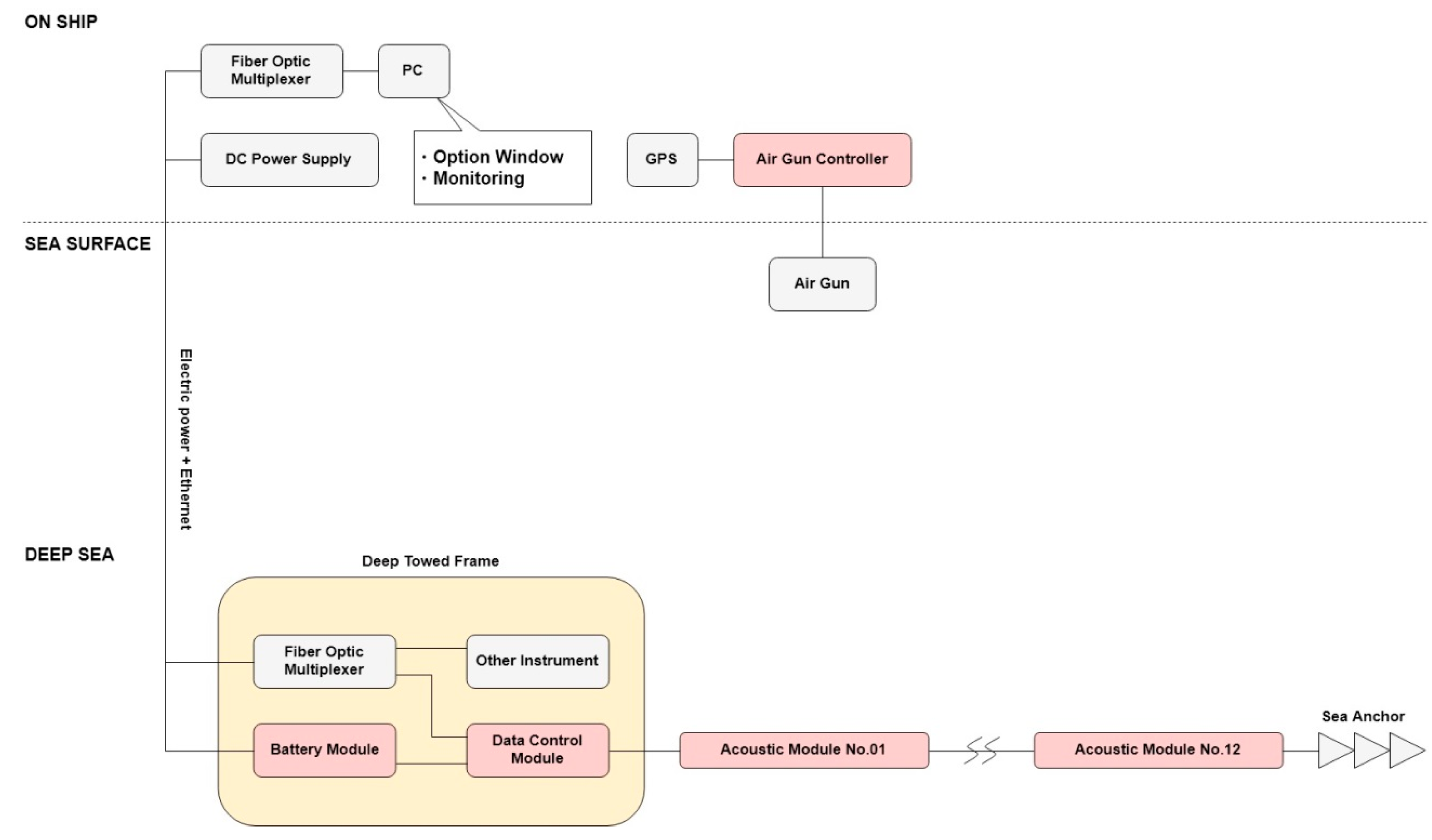
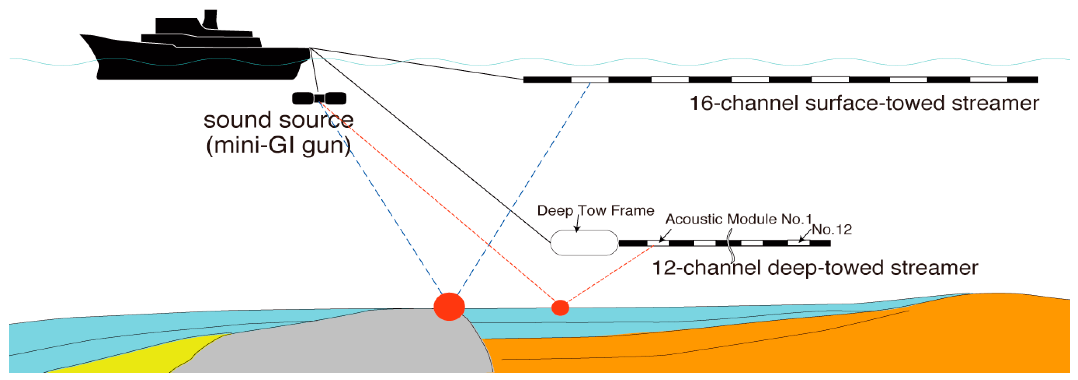
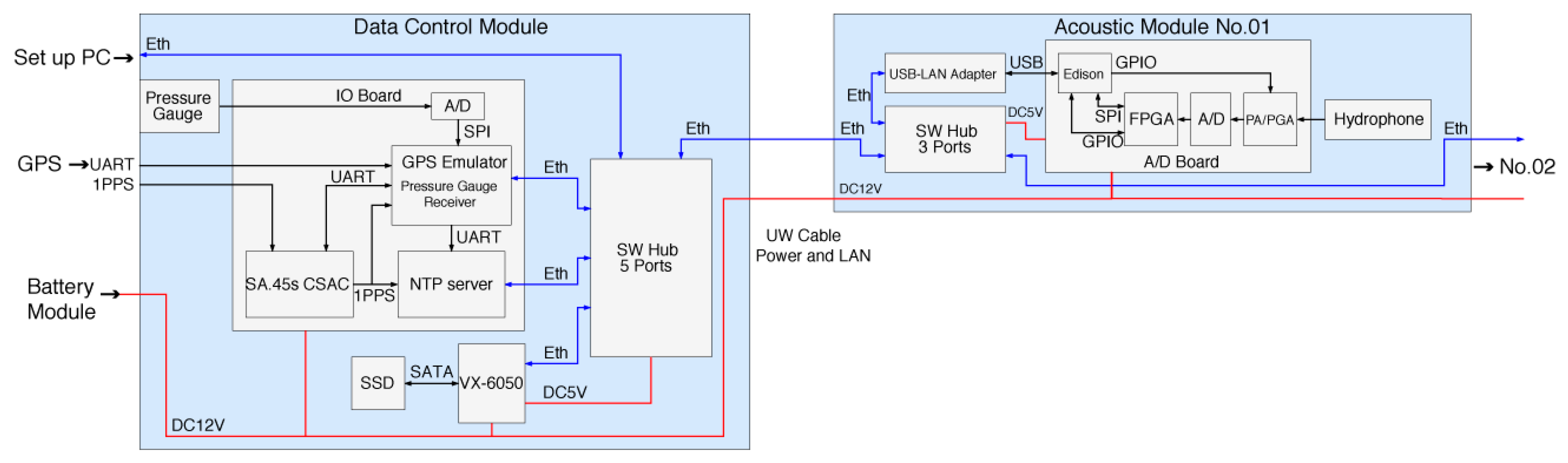
2. System Overview
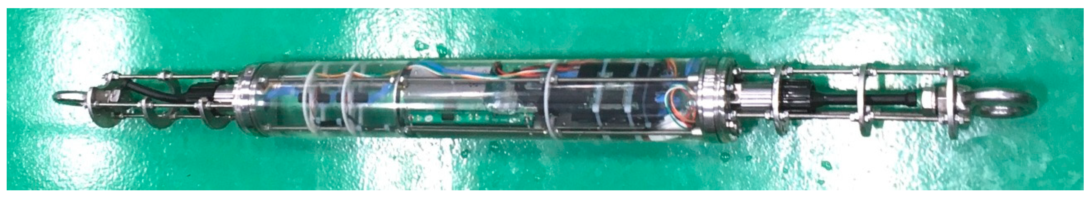
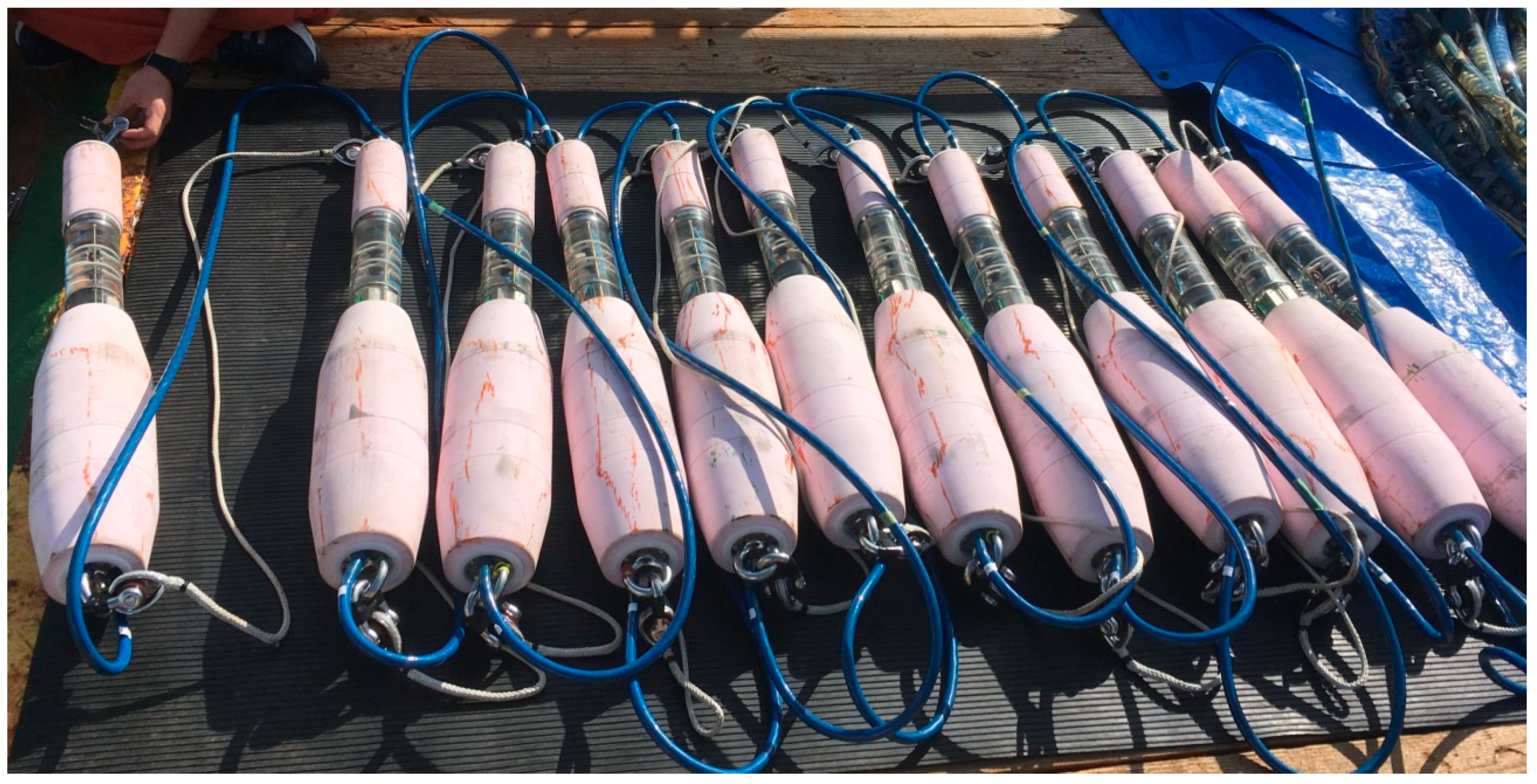
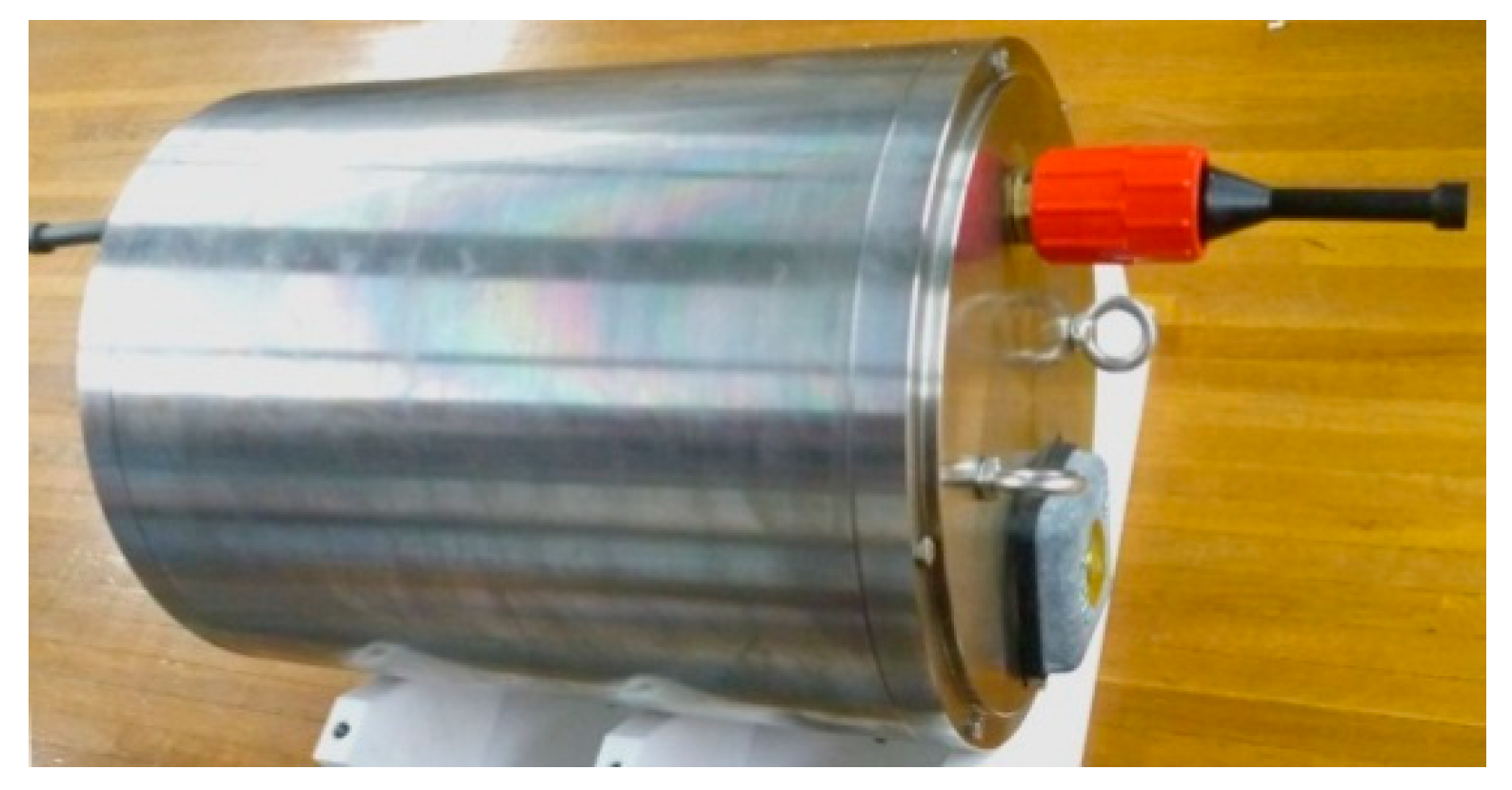
3. Description of the Modules
3.1. Data Control Module
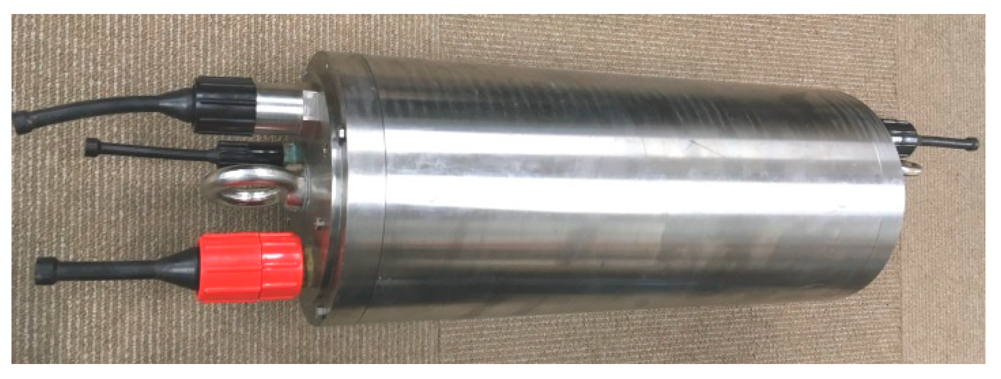
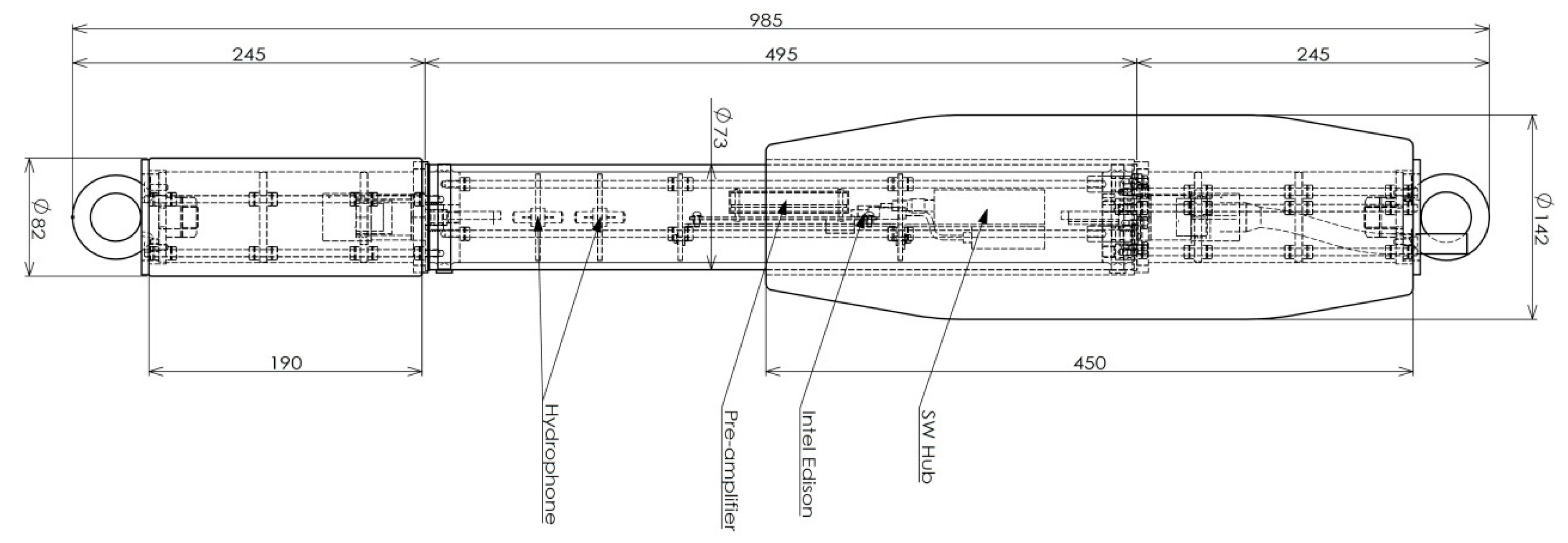
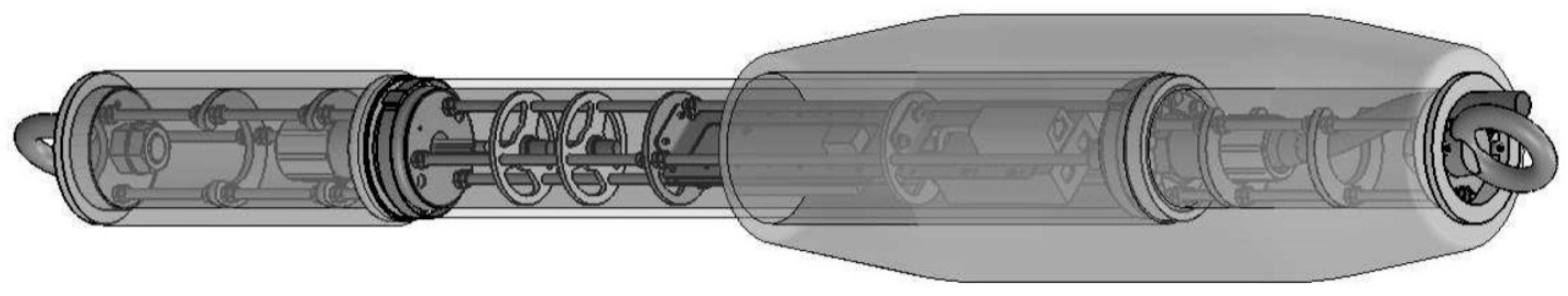
3.2. Acoustic Module
3.3. Battery Module
4. Specifications
| ⟡ Frequency response | 5 Hz to 15 kHz |
| ⟡ Sensitivity | −201 dBV re 1 µPa |
| ⟡ Depth | −2200 m |
| ⟡ Distance between acoustic modules | Flexible |
| ⟡ Number of acoustic modules | Flexible, normally 12, with a min of 1 and a max of 24 |
| ⟡ Operating time | 44 h with two battery modules and 12 acoustic modules with a 14.5 V DC 3 A power supply. |
| If a 14.5 V DC 5 A power supply is available, no restrictions on operating time. | |
| ⟡ Time management | Atomic clock with GPS signal receiver |
| ⟡ Amplifier gain | 26 dB to 66 dB in 8 steps |
| ⟡ Resolution power | 1.2 µPa in theory |
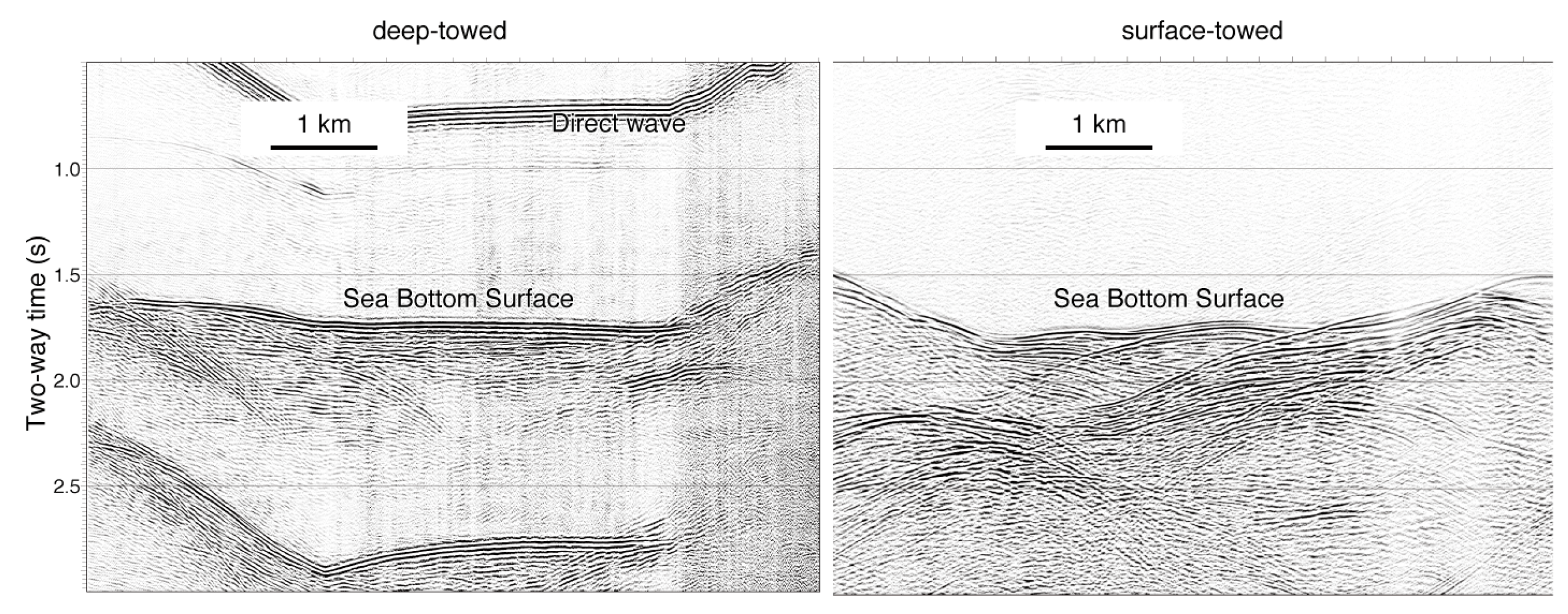
5. Test Data
6. Summary
Author Contributions
Funding
Acknowledgments
Conflicts of Interest
References
- Wood, W.; Gettrust, J.F.; Spychalski, S. A new deep-towed, multi-channel seismic system. Sea Technol. 2003, 44, 44–49. [Google Scholar]
- Chapman, N.R.; Gettrust, J.F.; Walia, R.; Hannay, D.; Spence, G.T.; Wood, W.T.; Hyndman, R.D. High Resolution deep-towed multichannel seismic survey of deep sea gas hydrates off western Canada. Geophysics 2002, 67, 1038–1047. [Google Scholar] [CrossRef]
- Lindsey, J. The Fresnel zone and its interpretative significance. Lead. Edge 1989, 8, 33–39. [Google Scholar] [CrossRef]
- Bowen, A.N. A High-Resolution Seismic Profiling System using a Deep-Towed Horizontal Hydrophone Streamer. Mar. Geophys. Res. 1984, 6, 275–293. [Google Scholar] [CrossRef]
- Nouze, H.; Sibuet, J.C.; Savoye, B.; Marsset, B.; Thomas, Y. Pasisar: Performances of a high and very high resolution hybrid deep-towed seismic device. Mar. Geophys. Res. 1997, 19, 379–395. [Google Scholar] [CrossRef]
- Inoue, T.; Arai, K.; Yokoyama, S.; Murakami, F.; Nishimura, K.; Yamazu, T.; Haragushi, K. OS13D-1530: High-resolution geological structure in deep sea area obtained by new developing deep towing multi-channel streamer system. In Proceedings of the AGU Fall Meeting, Washington, DC, USA, 10–14 December 2018. [Google Scholar]


© 2019 by the authors. Licensee MDPI, Basel, Switzerland. This article is an open access article distributed under the terms and conditions of the Creative Commons Attribution (CC BY) license (http://creativecommons.org/licenses/by/4.0/).
Share and Cite
Yamazu, T.; Haraguchi, K.; Inoue, T.; Arai, K. Development of a Highly Flexible and High-Resolution Deep-Towed Streamer. J. Mar. Sci. Eng. 2019, 7, 254. https://doi.org/10.3390/jmse7080254
Yamazu T, Haraguchi K, Inoue T, Arai K. Development of a Highly Flexible and High-Resolution Deep-Towed Streamer. Journal of Marine Science and Engineering. 2019; 7(8):254. https://doi.org/10.3390/jmse7080254
Chicago/Turabian StyleYamazu, Toshio, Koshi Haraguchi, Takahiko Inoue, and Kohsaku Arai. 2019. "Development of a Highly Flexible and High-Resolution Deep-Towed Streamer" Journal of Marine Science and Engineering 7, no. 8: 254. https://doi.org/10.3390/jmse7080254
APA StyleYamazu, T., Haraguchi, K., Inoue, T., & Arai, K. (2019). Development of a Highly Flexible and High-Resolution Deep-Towed Streamer. Journal of Marine Science and Engineering, 7(8), 254. https://doi.org/10.3390/jmse7080254