Article

Stability Analysis of Near-Wellbore Reservoirs Considering the Damage of Hydrate-Bearing Sediments

1
The Key Laboratory of Urban Security and Disaster Engineering of Ministry of Education, Beijing University of Technology, Beijing 100124, China
2
Institute of Geographic Sciences and Natural Resources Research, Chinese Academy of Sciences, Beijing 100101, China
*
Author to whom correspondence should be addressed.
J. Mar. Sci. Eng. 2019, 7(4), 102; https://doi.org/10.3390/jmse7040102
Submission received: 4 March 2019 / Revised: 31 March 2019 / Accepted: 9 April 2019 / Published: 13 April 2019
(This article belongs to the Special Issue Coastal Geohazard and Offshore Geotechnics)

Abstract

:
The stability of hydrate-bearing near-wellbore reservoirs is one of the key issues in gas hydrate exploitation. In most previous investigations, the damage evolution process of the sediment structure and its effect on near-wellbore reservoir stability have been neglected. Therefore, the damage variable is introduced into a multi-field coupled model based on continuous damage theory and multi-field coupling theory. A thermo-hydro-mechanical-chemical (THMC) multi-field coupling mathematical model considering damage of hydrate-bearing sediments is established. The effects of damage of hydrate-bearing sediments on the thermal field, seepage field, and mechanical field are considered. Finally, the distributions of hydrate saturation, pore pressure, damage variable, and effective stress of a near-wellbore reservoir in gas hydrate exploitation by depressurization are calculated, and the stability of a hydrate-bearing near-wellbore reservoir is analyzed using the model. Through calculation and analysis, it is found that structural damage of hydrate-bearing sediments has an adverse effect on the stability of hydrate-bearing near-wellbore reservoirs. The closer to the wellbore, the worse the reservoir stability, and the near-wellbore reservoir stability is the worst in the direction of minimum horizontal ground stress.

1. Introduction

As a new type of clean energy, natural gas hydrate has the advantages of large reserves, wide distribution, high energy density, and non-pollution [1]. However, the hydrate will dissociate during the process of exploitation, which will lead to a decrease in the mechanical strength of hydrate-bearing sediments, causing possibly shear failure of the hydrate-bearing reservoir and serious deformation of the ground. This will result in instability of hydrate-bearing near-wellbore reservoirs [2]. Therefore, it is of great theoretical significance and application value to evaluate the stability of hydrate-bearing near-wellbore reservoirs for ensuring safe gas hydrate exploitation.
The problems of reservoir stability such as wellbore instability and ground deformation during gas hydrate exploitation are essentially a multi-field coupling problem involving phase transition, fluid flow, heat transfer, and geomechanical deformation [3]. Freij-Ayoub et al. [4] established a hydrate-bearing wellbore stability analysis model considering the coupling of porous media deformation, heat transfer, fluid transport, and hydrate dissociation, but in this model the fluid was regarded as a single-phase flow without taking into account the effect of hydrate dissociation on reservoir permeability. Rutqvist et al. [5] proposed a multi-field coupled mathematical model considering thermal, fluid-flow, and geomechanical responses during hydrate dissociation, and the Mohr–Coulomb strength criterion was used to judge the shear failure of a wellbore reservoir under two gas hydrate exploitation schemes of a vertical well and a horizontal well. Finally, the wellbore reservoir stability was analyzed from the perspective of stratum subsidence and shear failure. Sun et al. [6] studied the stability of hydrate-bearing near-wellbore reservoirs under the condition of drilling fluid invasion in the Shenhu area. The results showed that the change in pore pressure and the decrease of the mechanical strength of the stratum caused by hydrate dissociation were the key factors affecting the stability of the wellbore reservoir. Sánchez et al. [7] proposed a fully coupled thermo-hydro-mechanical framework to study different problems involving hydrate-bearing sediments from laboratory tests to field-scale simulations, and ice formation and thawing were considered in the model. Sasaki et al. [8] proposed a modelling methodology of the well construction process for unconsolidated hydrate-bearing reservoirs, and the effect of wellbore construction on the integrity of the unconsolidated hydrate-bearing reservoir in the Nankai Trough was investigated. Sun et al. [9] proposed a fully coupled thermal–hydraulic–mechanical–chemical model to investigate the response of hydrate-bearing sediments during gas production, and a new thermodynamics-based constitutive model was introduced into the coupled model to simulate the mechanical behavior of hydrate-bearing sediments. In addition, the differences between fully coupled and semi-coupled models were analyzed. Yoneda et al. [10] developed a coupled thermo-hydro-mechanical (THM) simulator to evaluate the mechanical stability of a hydrate-bearing reservoir and well completion at the eastern Nankai Trough. The results showed that the mechanical deformation occurred in a much wider area than the range of hydrate dissociation and large shear stress occurred near the production well. Zhou et al. [11] used a fully coupled THM numerical simulator to examine the stability of a hydrate-bearing reservoir during gas production, and the critical state constitutive model for hydrate-bearing sediments was used to evaluate the mechanical response of the formation.
However, hydrate-bearing sediments are a kind of composite material composed of soil particles, hydrate, gas, and water, and the hydrate mainly exists in the form of filling, cementing, or supporting between the pores of soil particles; this makes hydrate-bearing sediments have certain structural properties, and their mechanical properties are much more complex than those of ordinary sediments. Therefore, it is generally assumed in the existing multi-field coupling models that hydrate-bearing sediments are a kind of elastic or ideal elastoplastic medium without considering the damage evolution process of the hydrate-bearing sediments and its influence on the multi-field coupling process. Some continuous damage models based on damage mechanics have been proposed to simulate the failure process of hydrate-bearing sediments. For example, Wu et al. [12] established the constitutive model of hydrate-bearing sediment considering damage based on the construction method of the frozen soil constitutive model and composite material theory. Liu et al. [13] proposed a damage statistical constitutive model of hydrate-bearing sediments combined with the meso-mechanical mixed model for the equivalent elastic modulus. However, the existing studies on damage statistical constitutive models of hydrate-bearing sediments are established on the assumption that the sediment micro-elements will be damaged at the beginning of loading and the bearing capacity of sediment micro-elements would be lost completely after the damage, which is not consistent with the fact.
Based on the above, a damage statistical constitutive model of hydrate-bearing sediments considering the effects of damage threshold and residual strength is established by introducing a three-parameter Weibull distribution and residual strength correction coefficient, and then the damage constitutive model is introduced into the multi-field coupled model. A thermo-hydro-mechanical-chemical multi-field coupling model considering the influence of damage of hydrate-bearing sediments on temperature, seepage, and mechanics during hydrate dissociation is established. Finally, the near-wellbore reservoir stability during gas hydrate exploitation is analyzed using the coupling model.

2. Theoretical Formulations

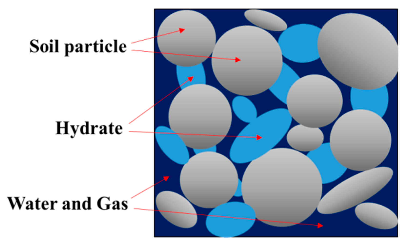
2.1. Damage Statistical Constitutive Model for Hydrate-Bearing Sediments

As shown in Figure 1, the skeleton of hydrate-bearing sediments is a grain-reinforced composite material composed of soil particles and hydrate. The cementation, pores, and internal defects randomly distributed within the sediments are the main factors of damage, and the micro-element strength is also randomly distributed. According to Yun et al. [14], the appearance of structure yield stress in the sediment indicated that debonding or partial hydrate breakage began to occur between soil particles and hydrates. Therefore, there should be a damage threshold point during the deformation process of hydrate-bearing sediments.
With increased loading, the hydrate-bearing sediments begin to suffer damage when the sediment micro-element strength exceeds the damage threshold. In this paper, the sediment yield stress point is regarded as the sediment damage threshold point, and the micro-element strength of the sediments is assumed to follow the three-parameter Weibull distribution.
The density function of the three-parameter Weibull distribution is [15]
f ( F ) = { 0 , F < γ m F 0 ( F γ F 0 ) m 1 exp [ ( F γ F 0 ) m ] , F γ
where m, F0, and γ are Weibull distribution parameters, and F is the hydrate-bearing sediment micro-intensity random distribution variable.
The damage variable D is defined as the ratio of the number of broken micro-elements to the total number of micro-elements:
D = N f N = F N f ( F ) d F N
where Nf is the number of broken micro-elements, and N is the total number of micro-elements.
By substituting Equation (1) into Equation (2), the evolution law of damage variable D when F > γ can be obtained as follows:
D = 1 exp [ ( F γ F 0 ) m ] .
The micro-element strength F can be described by using the Drucker–Prager strength criterion:
F = α 0 I 1 + J 2
where α0 is the material parameter, which is related to the internal friction angle φ; I1 is the first invariant of the stress tensor; and J2 is the second invariant of the deviator stress tensor.
According to the Lemaitre equivalent strain assumption [16],
ε = σ ˜ E = σ E ˜ = σ E ( 1 D )
where σ is the equivalent stress of the nominal stress σ ˜ , E is the elastic modulus of the non-damaged material, and is the elastic modulus of the damaged material.
In the current research on the hydrate-bearing sediment damage constitutive model, it has been usually assumed that the bearing capacity of the material will be lost completely after its failure [12,13]. However, its bearing capacity will not be completely lost due to the influence of the confining pressure and friction after micro-elements in the sediments are completely damaged, and it still has a certain residual strength [17]. In order to describe the damage process of sediments, the residual variable correction coefficient δ [18] is introduced, and Equation (5) is modified as follows:
ε = σ E ( 1 δ D ) .
Combined with Equations (3) and (6), the damage statistical constitutive model of hydrate-bearing sediments considering the damage threshold and residual strength after sediment damage is obtained as follows:
Δ σ = E ε 1 { 1 δ { 1 exp [ ( F γ F 0 ) m ] } } + ( 2 v 1 ) σ 3    ( F γ )   .
The starting point of sediment damage evolution is determined by parameter γ, namely, the damage threshold point (Δσd, ε1d). It is assumed that the sediment damage variable D is equal to 0 at the damage threshold point, which can be obtained by Fγ = 0 as follows:
γ = lim ε 1 ε 1 d ( α 0 I 1 + J 2 ) .

2.2. Multi-Field Coupling Model Considering Damage of Hydrate-Bearing Sediments

2.2.1. Mechanical Field Control Equations

In the initial stage of loading, the deformation of hydrate-bearing sediments is in the elastic stage, and the hydrate-bearing sediments’ stress–strain relationship considering the influence of temperature can be expressed as [19]
σ i j = λ δ i j ε k k + 2 G ε i j K α T δ i j ( T T 0 )
where σij is the effective stress tensor, εij is the strain tensor, λ and G are Lame constants, K′ is the drainage bulk modulus for porous media, αT is the volumetric thermal expansion coefficient, and T is temperature.
Combining Equations (7) and (9) with the generalized Biot’s effective stress principle [20], the small strain assumption theory, and the mechanical equilibrium equations of porous media, the governing equations of the mechanical field considering sediment damage can be expressed by the displacement u, the average pore pressure P, and the temperature T as follows:
E ˜ 2 ( 1 + v ) u i , j j + E ˜ 2 ( 1 + v ) ( 1 2 v ) u j , j i + α P , i + K α T T , i + F i = 0
where v is Poisson’s ratio, α is Biot’s consolidation coefficient, Fi and ui are the components of the volume force and displacement in the i direction, and and E are the elastic modulus after the damage and before the damage, respectively.
According to the elastic damage theory, the elastic modulus of sediments after damage is as follows:
E ˜ = E ( 1 D ) .
In addition, the average pore pressure can be given by pore water pressure and pore gas pressure:
P = S w S w + S g P w + S g S w + S g P g
P c = P g P w = p c e ( S w S w + S g S w r 1 S w r ) 0.65
where Pc is the capillary pressure [21] and Pce is the nominal capillary pressure.

2.2.2. Hydraulic Field Control Equations

Based on the continuity equation of fluid in porous media and Darcy’s law, multiphase fluid flow equations considering the influence of sediment skeleton deformation and temperature gradient are established as follows:
φ e S l ρ l t + φ e S l ρ l ε v t + ( K r l K ρ l μ l P l ρ l k T l T ) = m ˙ l
where subscript l represents the gas phase g and water phase w, Sl is the gas and water saturation, l is the gas and water production rate, and the gas production rate g during hydrate dissociation can be obtained from the Kim–Bishnoi hydrate dissociation kinetic model [22]. Pl is the pore gas pressure and pore water pressure, εv is the volume strain, μl is the dynamic viscosity coefficient of gas and water, φe is the effective porosity, φe = φ0(1 − Sh), φ0 is the porosity of porous media without hydrate, kTl is the diffusion rate of fluid under a temperature gradient, K is the absolute permeability of the porous media, K = K0(1 − Sh)n [23], K0 is the absolute permeability of porous media without hydrate, n is the permeability decline index, and Krl is the relative permeability of the gas and water phase, described by the modified Corey model [24].
Relevant research has suggested that damage would change the permeability of hydrate-bearing sediments, which will have an impact on the seepage process. It is assumed that the permeability and the damage variable have an exponential relationship [25]. In this paper, it is also assumed that the effect of sediment damage on the absolute permeability K meets the following criterion:
K ˜ = K exp ( α k D )
where K ˜ is the absolute permeability of the porous media affected by the damage, K is the absolute permeability of the porous media, and αk is the influence coefficient of the damage on the permeability.
In addition, the mass conservation equation of the hydrate is expressed as follows:
φ e S h ρ h t = m ˙ h .
Moreover, the gas phase saturation, water phase saturation, and hydrate saturation in the porous media can satisfy the following equation:
S g + S w + S h = 1 .

2.2.3. Energy Conservation Equation

As is known to all, the dissociation of gas hydrate depends on certain temperature and pressure conditions, and the dissociation of gas hydrate is an endothermic process. Temperature has a significant effect on hydrate dissociation. The energy conservation equation considering heat conduction, heat convection, hydrate dissociation endotherm, and soil skeleton deformation is established as follows:
( φ e S α ρ α c α ) T t = [ ( φ e S α λ α ) T ] [ ( ρ α v r α c α ) T ] K α T ( T T 0 ) ε v t + q h + q i n
where the subscript α denotes the gas phase g, the water phase w, or the hydrate phase h, and the soil skeleton phase s. Cα is the specific heat, λα is the heat transfer coefficient, qh is the latent heat of hydrate phase change, and qin is the external heat supply.
After damage of hydrate-bearing sediments, micro-cracks and pores will appear in the hydrate-bearing sediment reservoir; the fluid with a lower temperature may then infiltrate into it, which will affect the heat conductivity coefficient of materials [25]. Therefore, it is assumed that the effect of structural damage of sediments on the heat conductivity coefficient of materials satisfies the following assumption:
λ ˜ i = λ i exp ( α λ i D )
where subscript i denotes hydrate phase h or soil skeleton phase s; λ ˜ i and λi are the heat conductivity coefficients of the damaged and undamaged sediment skeleton, respectively; and αλi is the damage influence parameter on the heat conductivity coefficient.
In addition, the latent heat for the hydrate phase change satisfies [26]
q h = m ˙ h ( 56599 16.744 T ) M h .

3. Model Verification

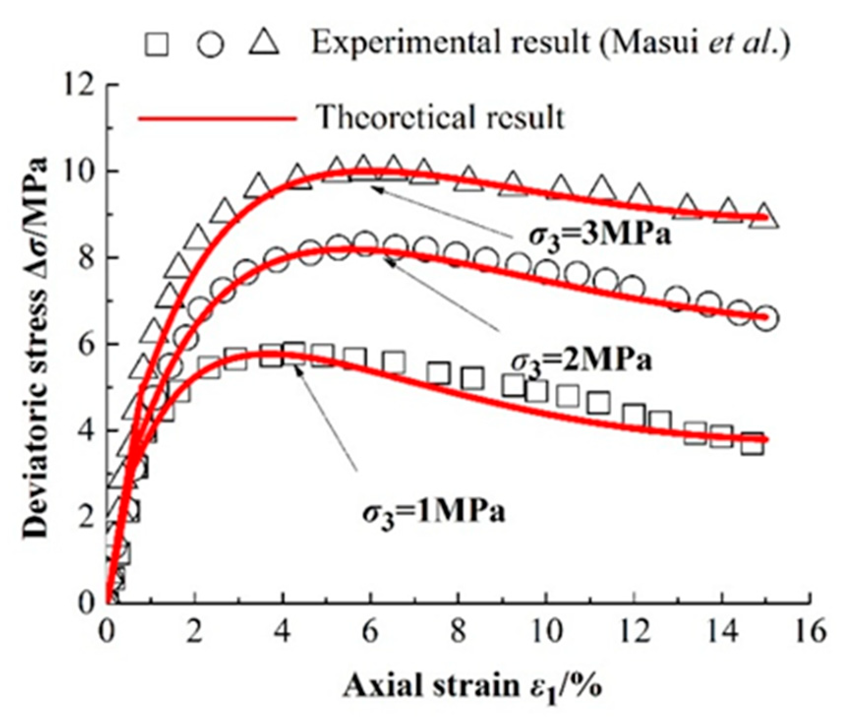
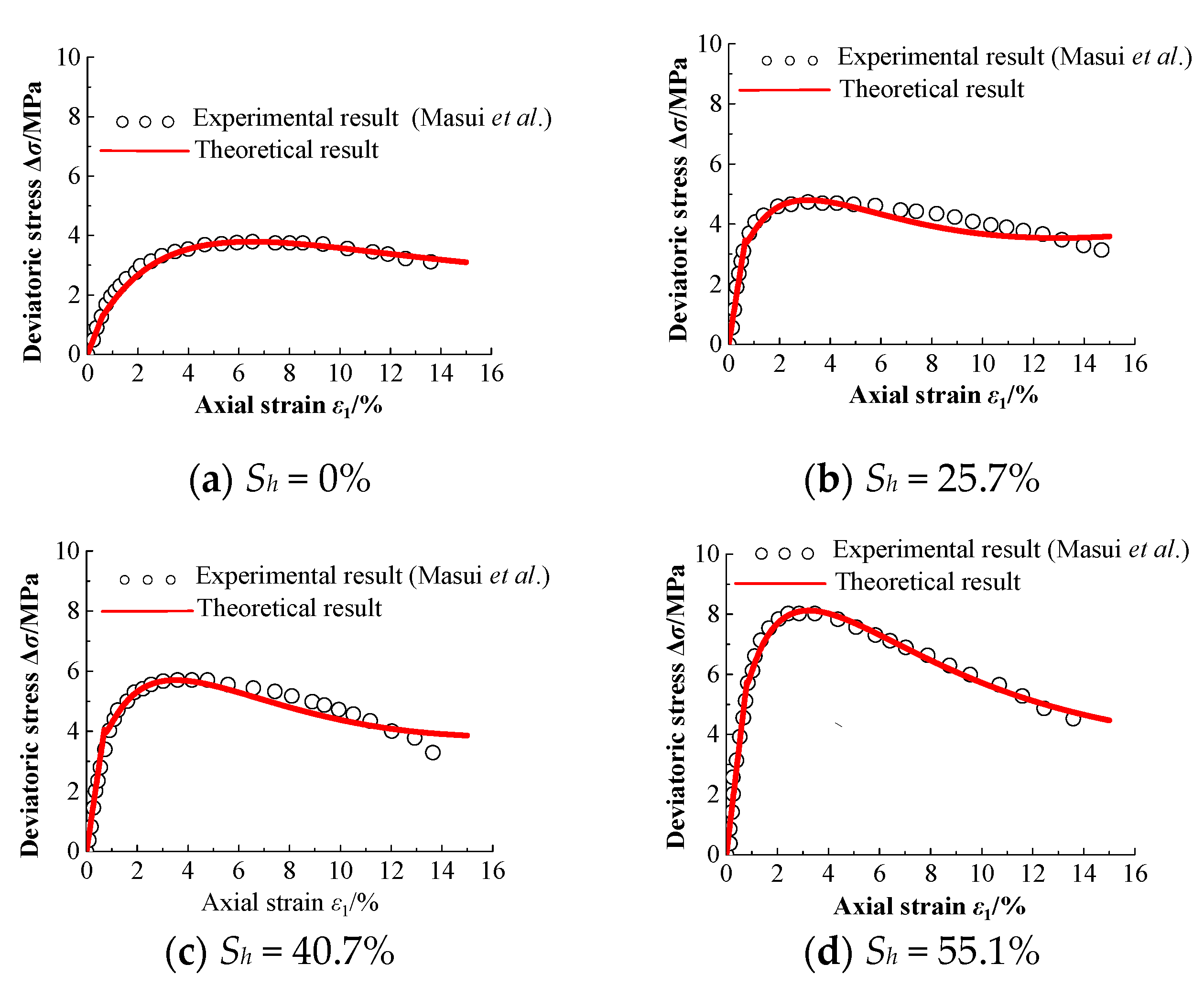
3.1. Verification of the Damage Statistical Constitutive Model of Hydrate-Bearing Sediments

In order to verify the rationality of the damage statistical constitutive model established in this paper, a comparative analysis was carried out by citing the experimental data from Masui et al. [27]. There are the parameters E, v, φ, m, F0, γ, and δ in the constitutive model. By handling the experimental data from Masui et al., E can be obtained as shown in Table 1, v = 0.219, and φ = 30°. The Weibull distribution parameters m and F0 can be calculated according to the characteristic points of the stress–strain curve [12] and γ is determined according to Equation (8); these values are also shown in Table 1. The residual strength correction coefficient δ can be determined from the experimental results using the inversion trial method. The confining pressure values σ3 in the experiments were 1.0 MPa, 2.0 MPa, and 3.0 MPa.
Figure 2 and Figure 3 show comparisons between the stress–strain theoretical curves of hydrate-bearing sediments and the experimental results by Masui et al. under different hydrate saturation and confining pressure values. As shown in the figures, with increased hydrate saturation and confining pressure, the strength and stiffness of the hydrate-bearing sediments also increased. It can be seen that the damage statistical constitutive model of hydrate-bearing sediments considering the damage threshold and residual strength proposed in this paper can better reflect the characteristics of the mechanical properties of hydrate-bearing sediments changing with hydrate saturation and confining pressure, and the results of the theoretical model are in good agreement with the experimental results.

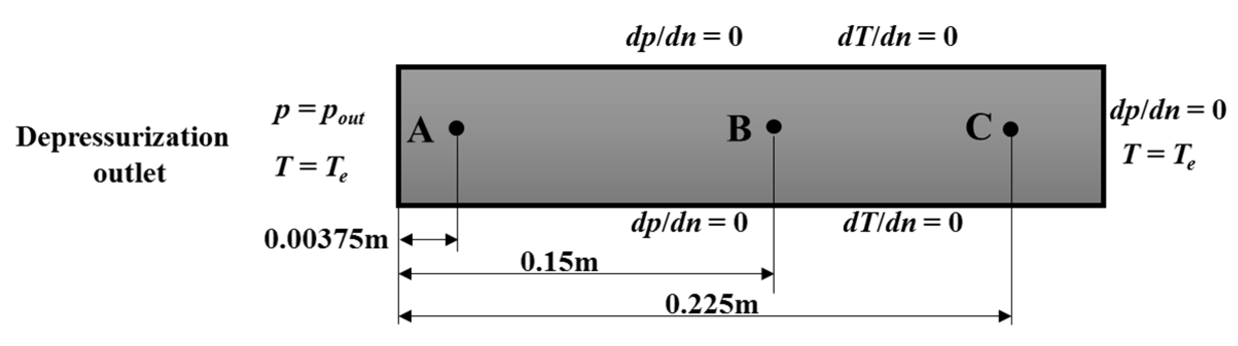
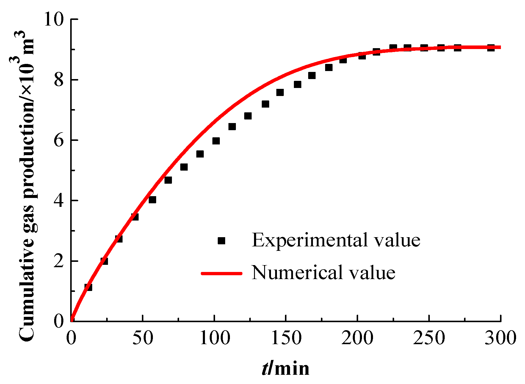
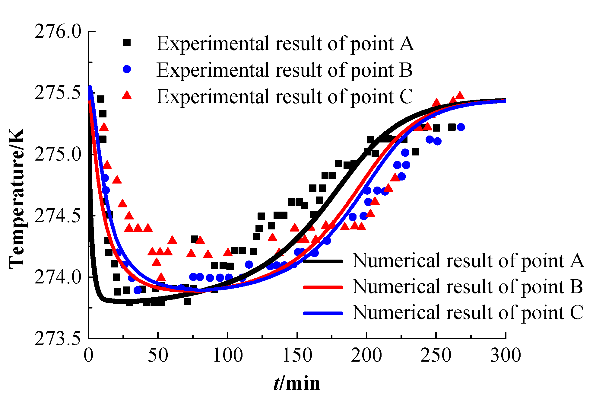
3.2. Verification of the Multi-Field Coupling Model

In order to verify the validity of the multi-field coupling model established in this paper, the experimental results of hydrate dissociation by depressurization with a Berea sandstone core sample by Masuda et al. [28] were compared. The hydrate dissociation by the depressurization model from Masuda et al. is shown in Figure 4. The model parameters selected for verification in this paper are completely consistent with the work by Masuda et al. From Figure 4, the core length is 0.3 m and the diameter is 0.051 m. Three reference points A, B, and C were selected for comparison. Point A is 0.00375 m away from the outlet, Point B is 0.15 m away from the outlet, and Point C is 0.225 m away from the outlet.
Figure 5 shows a comparison of the experimental and numerical results of cumulative gas production. It can be seen from Figure 5 that the result of cumulative gas production of the outlet simulated by the coupling model established in this paper is in good agreement with the Masuda experimental results, and the final gas production obtained by the numerical method is also close to the experimental value.
Figure 6 shows a comparison of the experimental and numerical results of the temperature at the three different positions A, B, and C of the sandstone core. It is clearly seen from Figure 6 that the temperature curves of the three measuring points A, B, and C simulated by the coupling model established in this paper are basically consistent with the overall trend of the Masuda experimental curves, which indicates that the multi-field coupling model established in this paper has good applicability and can be used for further analysis and calculation.

4. Numerical Solution of the Multi-Field Coupling Model Considering Hydrate-Bearing Sediment Damage

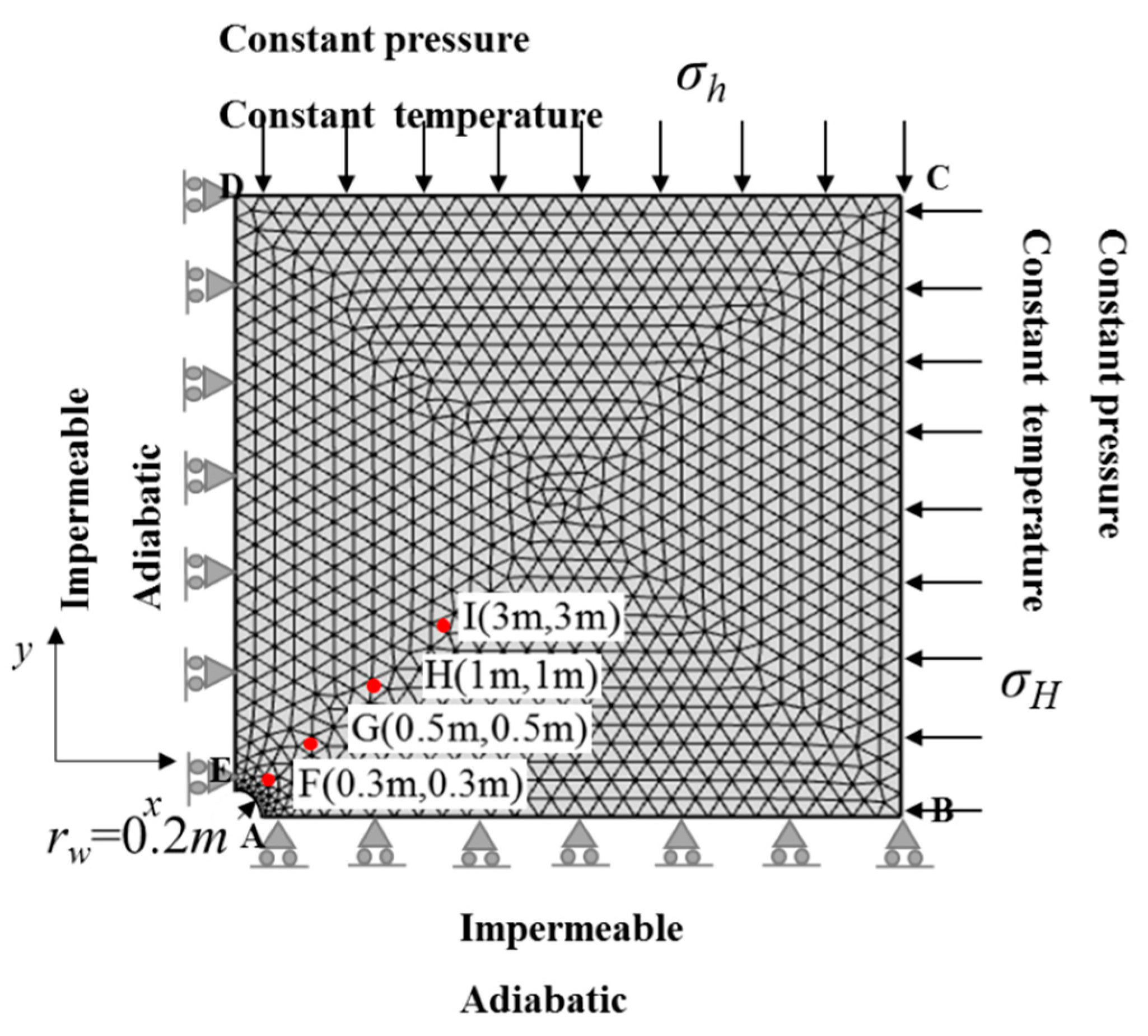
4.1. Multi-Field Coupling Model Numerical Calculation Conditions

In this paper, COMSOL Multiphysics was used to numerically solve the thermo-hydro-mechanical-chemical (THMC) multi-field coupling mathematical model considering damage of hydrate-bearing sediments, and the stability of the near-wellbore reservoir was analyzed. A simplified 1/4 axisymmetric model of a hydrate-bearing near-wellbore reservoir is shown in Figure 7. The geometric size of the finite element model was 20 m × 20 m, and the borehole radius was 0.2 m. Mechanical field boundary conditions were set as follows: The maximum horizontal in situ stress σH and the minimum horizontal in situ stress σh were applied to the sides of BC and CD, respectively. The vertical displacement and horizontal displacement were respectively restricted on the sides of AB and DE. Hydraulic field boundary conditions were set as follows: the initial pore pressure boundary on the sides of BC and CD, impermeable boundaries at AB and DE, a depressurization boundary at AE, and a constant pressure P = 2.84 MPa at the bottom hole were set in the simulation. Thermal field boundary conditions were set as follows: the boundaries of BC and CD were constant-temperature boundaries and the boundaries of AB and DE were adiabatic boundaries. The main model parameters were selected from Masui et al. [27] and Liu et al. [29]. The physical and mechanical parameters of the hydrate-bearing sediments are shown in Table 2, and the thermodynamic parameters are shown in Table 3.

4.2. Numerical Results and Analysis

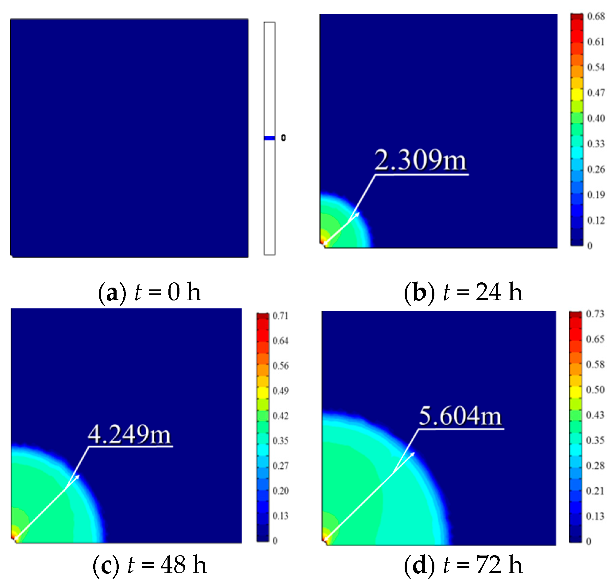
4.2.1. The Evolution of Hydrate Saturation in the Reservoir

In order to analyze the stability of a near-wellbore reservoir in hydrate-bearing sediments, the distributions of results within 10 m from the wellbore are given. Figure 8 shows the spatial evolutions of hydrate saturation in the near-wellbore reservoir at different times. The hydrate dissociation in the initial stage of gas hydrate exploitation is mainly concentrated around the exploitation well. With the development of exploitation, the hydrate dissociation proceeds along a circular dissociation plane, and the dissociation range expands continuously. The farther the stratum away from the wellbore, the lower the degree of hydrate dissociation. After 72 h of hydrate exploitation, the hydrate dissociation front reaches approximately 6.492 m from the center of the wellbore. Figure 9 shows the curves of hydrate saturation with time at different positions. As the hydrate exploitation progresses, the hydrate saturation of the hydrate-bearing reservoir decreases continuously. For example, the point H starts to dissociate at about t = 7.5 h, and the point I begins to dissociate at about t = 12 h, which indicates that the hydrate will dissociate earlier when it is closer to the wellbore. Then, it can be seen that there is a clear dissociation front during the process of hydrate dissociation.

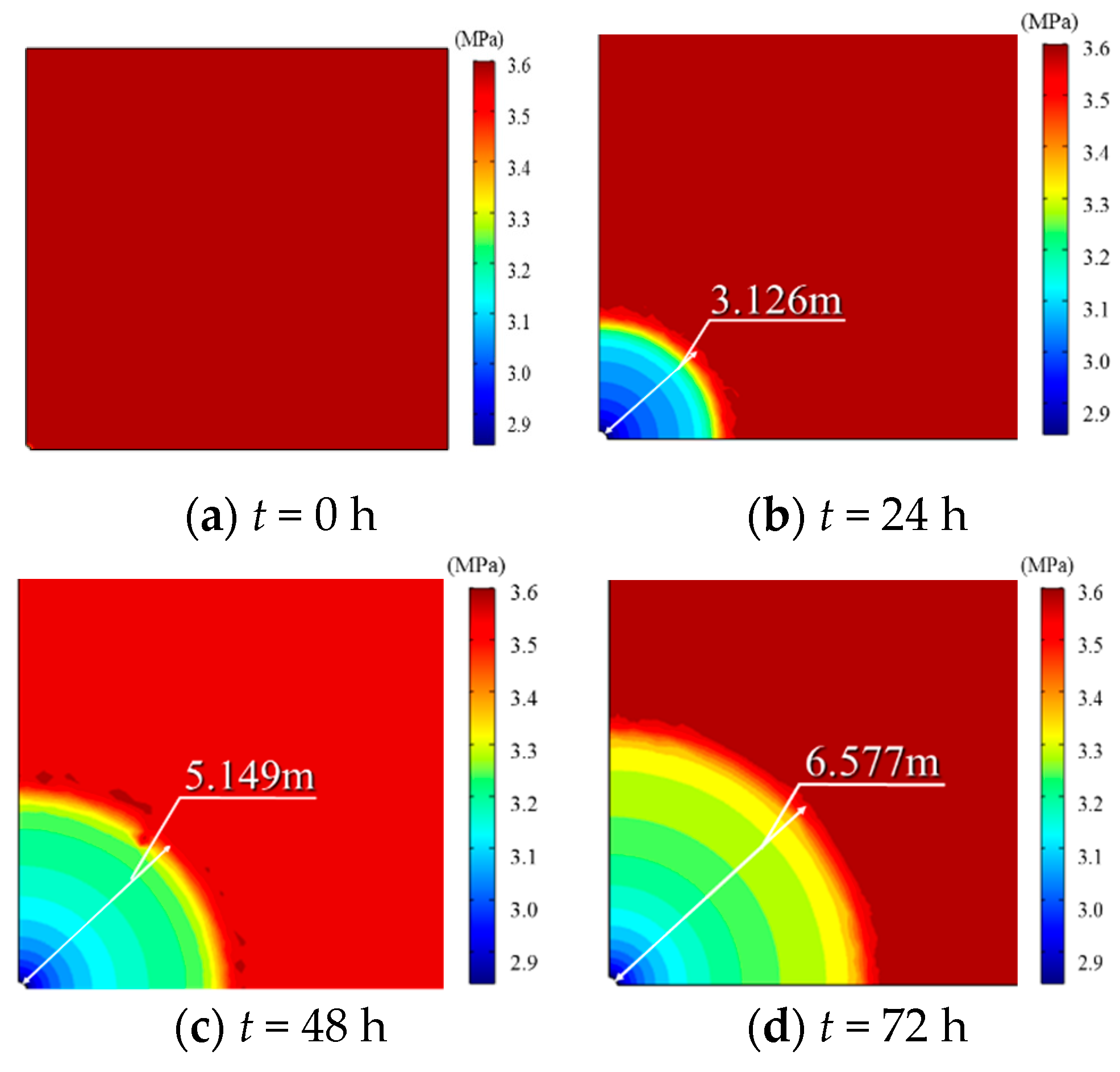
4.2.2. The Evolution of Pore Pressure in the Reservoir

Figure 10 shows the spatial evolutions of the average pore pressure in the near-wellbore reservoir at different times. As the gas hydrate exploitation goes on, the area of depressurization is expanding, and there is a large pressure gradient at the pressure front. After 72 h of hydrate exploitation, the reservoir pressure front reaches approximately 6.577 m from the center of the wellbore. Figure 11 shows the curves of the average pore pressure with time at different positions. From Figure 11, the average pore pressure in the reservoir is continuously decreasing at the initial stage of hydrate dissociation but increasing gradually with the process of hydrate dissociation. Due to the continuous hydrate dissociation and structural damage of sediments, the bearing capacity of the stratum will decrease, and the stress in the stratum will transfer to water and gas gradually, resulting in increased average pore pressure in the reservoir.

4.2.3. The Evolution of the Damage Area in the Reservoir

Figure 12 shows the spatial evolutions of the damage area in the near-wellbore reservoir at different times. It can be seen from Figure 12 that with continuous hydrate dissociation, the damage area of the hydrate-bearing reservoir shows a trend of continuous expansion. When t = 72 h, the damage radius has expanded to 5.604 m, and the maximum damage variable has also increased to 0.73. With the effect of non-uniform horizontal in situ stress, the maximum value of the damage variable of the hydrate-bearing reservoir appears in the direction of minimum horizontal in situ stress of the wellbore, which is the priority position of wellbore instability. Figure 13 shows the curves of the average damage area with time at different positions. At the beginning of hydrate dissociation, the damage variable of hydrate-bearing sediments remains zero. When a certain time is exceeded, the damage variable increases gradually, and the closer the position to the wellbore, the more serious the damage of the reservoir. This is due to the fact that sediment damage will only occur when the micro-element strength of sediments reaches the damage threshold. In addition, due to the hydrate dissociation and drilling, the original equilibrium state of the reservoir is destroyed; stress concentration occurs in the hydrate-bearing near-wellbore reservoir, which will cause more serious damage of the hydrate-bearing near-wellbore reservoir.

4.2.4. Stability Analysis of the Near-Wellbore Reservoir

Figure 14 shows the distribution of shear stress in the hydrate-bearing near-wellbore reservoir. As shown in Figure 14, hydrate dissociation and drilling destroy the original equilibrium state of the formation. Under the effect of non-uniform in situ stress, stress concentration occurs in the hydrate-bearing near-wellbore reservoir, which easily leads to instability of the reservoir. The curves of the effective stress at Point F with and without considering damage of hydrate-bearing sediments are shown in Figure 15. According to the principle of effective stress, the average pore pressure of the hydrate-bearing near-wellbore reservoir decreases in the early stage of gas hydrate exploitation, and then the effective stress rises rapidly. However, the effective stress of the hydrate-bearing reservoir decreases with the continuous dissociation of gas hydrates. This is because of the hydrate in the sediments gradually dissociating and the structural damage of sediments; the skeleton stress gradually transfers to water and gas, which causes a reduction in the effective stress and a decline in the bearing capacity of the stratum. Therefore, the phenomenon of partial softening and stress release occurs in the near-wellbore reservoir. Furthermore, it can be seen from Figure 15 that the phenomenon of stress softening under the condition of considering sediment damage is more obvious than that without considering sediment damage.
Figure 16 shows the effective principal stress path with and without considering damage of hydrate-bearing sediments, and the Mohr–Coulomb strength criterion was used to judge the shear failure of the wellbore reservoir. It is observed from Figure 16 that the effective principal stress in the near-wellbore reservoir does not eventually reach the Mohr–Coulomb failure surface. However, the effective principal stress path is closer to the Mohr–Coulomb failure surface when considering the damage of hydrate-bearing sediments, which indicates that the damage of hydrate-bearing sediments has an adverse effect on the stability of the near-wellbore reservoir.
Based on the Mohr–Coulomb failure criterion, the reservoir stability coefficient Fb was defined [30]. When Fb ≤ 1, the reservoir is unstable, and the smaller Fb is, the worse the reservoir stability is. When Fb > 1, the reservoir is in a stable state.
F b = 2 c cos φ ( σ 1 + σ 3 ) sin φ ( σ 1 σ 3 ) sin 2 φ ( σ 1 σ 3 ) cos 2 φ
Figure 17 shows the distributions of polar coordinates of the reservoir stability coefficient with and without considering damage of hydrate-bearing sediments at different positions. It is clearly seen from Figure 17 that the hydrate-bearing near-wellbore reservoir is relatively unstable in the directions of θ = 90° and θ = 270° around the wellbore, and the reservoir in the directions of θ = 0° and θ = 180° is relatively stable. This is because under the effect of non-uniform in situ stress, the near-wellbore reservoir stress in the direction of the minimum horizontal in situ stress is the most concentrated. Coupled with the decrease in the formation strength caused by sediment structural damage and hydrate dissociation, the reservoir instability area in this direction, which is the priority position of mechanical instability, is further expanding.
Figure 18 shows the curves of the vertical deformation of Point F with and without considering damage of hydrate-bearing sediments. When t = 72 h, the vertical deformation of Point F is uy = −0.0011 m (the negative value indicates compression deformation) without considering the influence of sediment damage but uy = −0.0016 m with considering the influence of sediment damage. The vertical deformation is increased by approximately 45.5% compared to the case where the influence of sediment damage is not considered. This indicates that when the influence of sediment damage is taken into account, greater deformation of the near-wellbore reservoir is predicted.
On the one hand, with hydrate dissociation, the cementation strength of hydrate-bearing sediments gradually decreases, and its capacity for resisting deformation also decreases. On the other hand, with the development of soil deformation, the damage degree of hydrate sediments will be aggravated. Therefore, if damage of hydrate-bearing sediments during the dissociation of gas hydrates in the multi-field coupling process is ignored, the bearing capacity of the hydrate-bearing reservoir will be overestimated, which will bring certain safety risks to hydrate exploitation.

5. Conclusions

In most previous investigations, the damage evolution process of sediment structure and its effect on multi-field coupling models and near-wellbore reservoir stability have been neglected. Moreover, the existing studies on damage statistical constitutive models of hydrate-bearing sediments were established on the assumption that the sediment micro-elements are damaged at the beginning of loading and that the bearing capacity of sediment micro-elements would be lost completely after damage, which is not consistent with the fact. Based on continuous damage theory, a damage statistical constitutive model of hydrate-bearing sediments considering the influence of the damage threshold and residual strength was established, and the damage variable was introduced into a THMC multi-field coupling mathematical model. The effects of hydrate-bearing sediment damage on the thermal field, hydraulic field, and mechanical field were considered. Then, the distributions of hydrate saturation, pore pressure, damage variable, and effective stress of the near-wellbore reservoir were discussed in detail, and the stability of the hydrate-bearing near-wellbore reservoir was analyzed. The following conclusions are drawn:
(1)
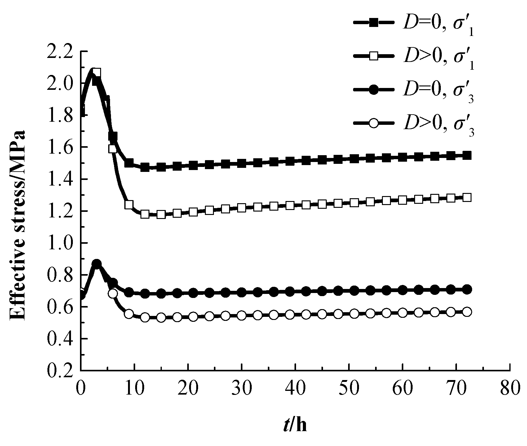
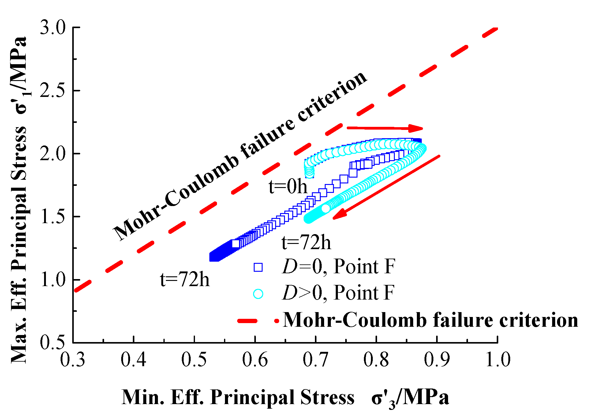
With continuous hydrate dissociation, the cementation of the sediment gradually decreases, and the structural damage gradually increases; this will lead to the partial softening and stress release of the stratum and will result in the decline of the bearing capacity of the reservoir. Therefore, damage of hydrate-bearing sediments has an adverse impact on the stability of the near-wellbore reservoir.
(2)
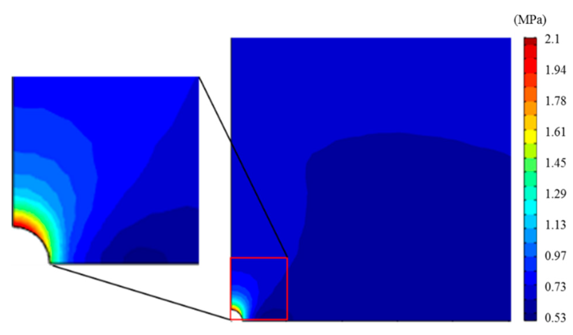
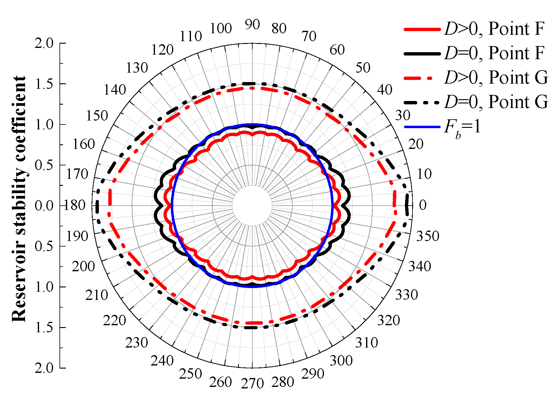
Under the effect of non-uniform horizontal in situ stress, the stress in the direction of minimum horizontal in situ stress is the most concentrated. Coupled with the reservoir strength reduction caused by hydrate dissociation and structural damage of sediments, the reservoir instability zone in this direction which is the priority position of mechanical instability, further expands.
(3)
Affected by the wellbore effect and hydrate dissociation, reservoirs near the wellbore are more susceptible to instability when compared with reservoirs farther from the wellbore.
(4)
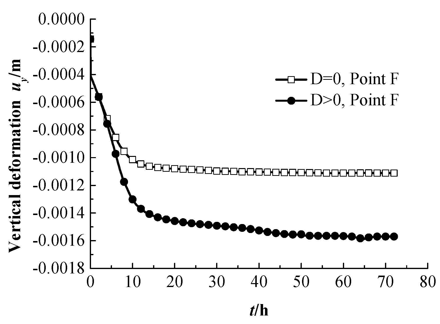
With continuous hydrate dissociation, the cementation structure of sediments is gradually damaged, and the capacity of the reservoir for resisting deformation also declines. In practical engineering, the hydrate dissociation caused by gas hydrate exploitation may lead to obvious seabed deformation.

Author Contributions

This research article was finished by X.Z., F.X., C.X., and Y.H. The statements of author contributions are as follows: conceptualization, X.Z. and F.X.; methodology, C.X.; writing—original draft preparation, F.X.; writing—review and editing, X.Z.; funding acquisition, Y.H.

Funding

The authors would like to appreciate the funding support from the National Natural Science Foundation of China (grant number 51778020) and the Innovative Research Group Project of National Natural Science Foundation of China (grant number 51421005).

Conflicts of Interest

All authors have read and approve this version of the article, and due care has been taken to ensure the integrity of the work. No part of this paper has been published or submitted elsewhere. No conflict of interest exists in the submission of this manuscript.

References

  1. Klauda, J.B.; Sandler, S.I. Global distribution of methane hydrate in ocean sediment. Energy Fuels 2005, 19, 459–470. [Google Scholar] [CrossRef]
  2. Sun, J.X.; Zhang, L.; Ning, F.L.; Lei, W.; Liu, L.; Hu, W.; Lu, H.; Lu, J.; Liu, C.; Jiang, G.; et al. Exploitation potential and stability of hydrate-bearing sediments at the site GMGS3-W19 in the South China Sea: A preliminary feasibility study. Mar. Pet. Geol. 2017, 86, 447–473. [Google Scholar] [CrossRef]
  3. Moridis, G.J.; Collett, T.S.; Pooladi-darvish, M.; Hancock, S.H.; Santamarina, J.C.; Boswell, R.; Kneafsey, T.J.; Rutqvist, H.; Kowalsky, M.B.; Reagan, M.T.; et al. Challenges, uncertainties, and issues facing gas exploitation from gas-hydrate deposits. SPE Reserv. Eval. Eng. 2011, 14, 76–112. [Google Scholar] [CrossRef]
  4. Freij-Ayoub, R.; Tan, C.; Clennell, B.; Tohidi, B.; Yang, J. A wellbore stability model for hydrate bearing sediments. J. Pet. Sci. Eng. 2007, 57, 209–220. [Google Scholar] [CrossRef]
  5. Rutqvist, J.; Moridis, G.J.; Grover, T.; Silpngarmlert, S.; Collett, T.S.; Holdich, S.A. Coupled multiphase fluid flow and wellbore stability analysis associated with gas exploitation from oceanic hydrate-bearing sediments. J. Pet. Sci. Eng. 2012, 92, 65–81. [Google Scholar] [CrossRef]
  6. Sun, J.X.; Ning, F.L.; Lei, H.W.; Gai, X.R.; Sánchez, M.; Lu, J.A.; Li, Y.L.; Liu, L.L.; Liu, C.L.; Wu, N.Y.; et al. Wellbore stability analysis during drilling through marine gas hydrate-bearing sediments in Shenhu area: A case study. J. Pet. Sci. Eng. 2018, 170, 345–367. [Google Scholar] [CrossRef]
  7. Sánchez, M.; Santamarina, C.; Teymouri, M.; Gai, X. Coupled numerical modeling of gas hydrate bearing sediments: from laboratory to field-scale analyses. J. Geophys. Res. Solid Earth 2018, 123, 10326–10348. [Google Scholar] [CrossRef]
  8. Sasaki, T.; Soga, K.; Mohammed, Z. Simulation of wellbore construction in offshore unconsolidated methane hydrate-bearing formation. J. Nat. Gas Sci. Eng. 2018, 60, 312–326. [Google Scholar] [CrossRef]
  9. Sun, X.; Luo, H.; Soga, K. A coupled thermal–hydraulic–mechanical–chemical (THMC) model for methane hydrate bearing sediments using COMSOL Multiphysics. J. Zhejiang Univ. Sci. A Appl. Phys. Eng. 2018, 19, 600–623. [Google Scholar] [CrossRef]
  10. Yoneda, J.; Takiguchi, A.; Ishibashi, T.; Yasui, A.; Mori, J.; Kakumoto, M.; Aoki, K.; Tenma, N. Mechanical response of reservoir and well completion of the first offshore methane-hydrate production test at the eastern Nankai Trough: A coupled thermo-hydromechanical analysis. SPE J. 2018. [Google Scholar] [CrossRef]
  11. Zhou, M.; Soga, K.; Yamamoto, K.; Huang, H.W. Geomechanical responses during depressurization of hydrate-bearing sediment formation over a long methane gas production period. Geomech. Energy Environ. 2018, in press. [Google Scholar] [CrossRef]
  12. Wu, E.L.; Wei, C.F.; Wei, H.Z.; Yan, R.T. A statistical damage constitutive model of hydrate-bearing sediments. Rock Soil Mech. 2013, 34, 60–65. [Google Scholar]
  13. Liu, L.L.; Zhang, X.H.; Liu, C.L.; Ye, Y.G. Triaxial shear tests and statistical analyses of damage for methane hydrate-bearing sediments. Chin. J. Theor. Appl. Mech. 2016, 48, 720–729. [Google Scholar]
  14. Yun, T.S.; Santamarina, J.C.; Ruppel, C. Mechanical properties of sand, silt and clay containing tetrahydrofuran hydrate. J. Geophys. Res. Solid Earth 2007, 112. [Google Scholar] [CrossRef]
  15. Weibull, W. A Statistical distribution function of wide applicability. J. Appl. Mech. 1951, 18, 293–297. [Google Scholar]
  16. Lemaitre, J. How to use damage mechanics. Nucl. Eng. Des. 1984, 80, 233–245. [Google Scholar] [CrossRef]
  17. Li, Y.L.; Liu, C.L.; Liu, L.L. Damage statistic constitutive model of hydrate-bearing sediments and the determination method of parameters. Acta Pet. Sin. 2016, 37, 1273–1279. [Google Scholar]
  18. Cao, R.L.; He, S.H.; Wei, J.; Wang, F. Study of modified statistical damage softening constitutive model for rock considering residual strength. Rock Soil Mech. 2013, 34, 1652–1660. [Google Scholar]
  19. Mctigue, D.F. Thermoelastic response of fluid-saturated porous rock. J. Geophys. Res. Solid Earth 1986, 91, 9533–9542. [Google Scholar] [CrossRef]
  20. Biot, M.A. General theory of three dimensional consolidation. J. Appl. Phys. 1941, 12, 155–164. [Google Scholar] [CrossRef]
  21. Sun, X.; Nanchary, N.; Mohanty, K.K. 1-D modeling of hydrate depressurization in porous media. Transp. Porous Media 2005, 58, 315–338. [Google Scholar] [CrossRef]
  22. Kim, H.C.; Bishnoi, P.R.; Heidemann, R.A.; Rizvi, S.S.H. Kinetics of methane hydrate decomposition. Chem. Eng. Sci. 1987, 42, 1645–1653. [Google Scholar] [CrossRef]
  23. Masuda, Y.S.; Naganawa, S.; Sato, K. Numerical calculation of gas hydrate production performance from reservoirs containing natural gas hydrates. In Proceedings of the SPE Asia Pacific Oil and Gas Conference, Kuala Lumpur, Malaysia, 14–16 April 1997. [Google Scholar]
  24. Corey, A.T. The interrelation between oil and gas relative permeabilities. Prod. Mon. 1954, 19, 38–41. [Google Scholar]
  25. Zhu, W.C.; Wei, C.H.; Tian, J.; Yang, T.H.; Tang, C.A. Coupled thermal-hydraulic-mechanical model during rock damage and its preliminary application. Rock Soil Mech. 2009, 30, 3851–3857. [Google Scholar]
  26. Selim, M.S.; Sloan, E.D. Heat and mass transfer during the dissociation of hydrates in porous media. AIChE J. 2010, 35, 1049–1052. [Google Scholar] [CrossRef]
  27. Masui, A.; Haneda, H.; Ogata, Y.; Aoki, K. Effect of methane hydrate formation on shear strength of synthetic methane hydrate sediments. In Proceedings of the 15th International Offshore and Polar Engineering Conference. Seoul: International Society of Offshore and Polar Engineers, Seoul, Korea, 19–24 June 2005. [Google Scholar]
  28. Masuda, Y.S.; Fujinaga, Y.; Naganawa, S.; Fujita, K. Modeling and experimental studies on dissociation of methane gas hydrates in berea sandstone cores. In Proceedings of the Third International Conference on Gas Hydrates, Salt Lake City, UT, USA, 18–22 July 1999. [Google Scholar]
  29. Liu, L.L.; Lu, X.B.; Zhang, X.H. Numerical study on porous media’s deformation due to natural gas hydrate dissociation considering fluid-soild coupling. Nat. Gas Geosci. 2013, 24, 1079–1085. [Google Scholar]
  30. Chen, W.F.; Saleeb, A.F. Elasticity and Plasticity; China Architecture and Building Press: Beijing, China, 2005. [Google Scholar]
Figure 1. Diagram of the structure of hydrate-bearing sediments.
Jmse 07 00102 g001
Figure 2. Comparisons of stress–strain theoretical curves and test curves of hydrate-bearing sediments under different hydrate saturations. (a) Sh = 0%; (b) Sh = 25.7%; (c) Sh = 40.7%; (d) Sh = 55.1%.
Jmse 07 00102 g002
Figure 3. Comparison of stress–strain theoretical curves and test curves of hydrate-bearing sediments under different confining pressures.
Jmse 07 00102 g003
Figure 4. Diagram of the model used in the hydrate dissociation experiment by Masuda et al.
Jmse 07 00102 g004
Figure 5. Comparison of experimental and numerical results of cumulative gas production.
Jmse 07 00102 g005
Figure 6. Comparisons of experimental and numerical results of the temperature at the three different positions A, B, and C of the sandstone core.
Jmse 07 00102 g006
Figure 7. Diagram of the hydrate-bearing near-wellbore reservoir.
Jmse 07 00102 g007
Figure 8. Spatial evolution of hydrate saturation of strata at different times. (a) Hydrate saturation in the reservoir at t = 0 h; (b) Hydrate saturation in the reservoir at t = 24 h; (c) Hydrate saturation in the reservoir at t= 48 h; (d) Hydrate saturation in the reservoir at t = 72 h.
Jmse 07 00102 g008
Figure 9. Curves of hydrate saturation with time at different positions.
Jmse 07 00102 g009
Figure 10. Spatial evolution of the average pore pressure of strata at different times. (a) Average pore pressure in the reservoir at t = 0 h; (b) Average pore pressure in the reservoir at t = 24 h; (c) Average pore pressure in the reservoir at t = 48 h; (d) Average pore pressure in the reservoir at t = 72 h.
Jmse 07 00102 g010
Figure 11. Curves of average pore pressure with time at different positions.
Jmse 07 00102 g011
Figure 12. Spatial evolution of the damage area of strata at different times. (a) Damage area at t = 0 h; (b) Damage area at t = 24 h; (c) Damage area at t = 48 h; (d) Damage area at t = 72 h.
Jmse 07 00102 g012
Figure 13. Curves of the damage variable with time at different positions.
Jmse 07 00102 g013
Figure 14. The distribution of shear stress of a hydrate-bearing near-wellbore reservoir.
Jmse 07 00102 g014
Figure 15. Curves of the effective stress of Point F with and without considering damage of hydrate-bearing sediments.
Jmse 07 00102 g015
Figure 16. Stress paths with and without considering damage of hydrate-bearing sediments.
Jmse 07 00102 g016
Figure 17. The distributions of polar coordinates of the reservoir stability coefficient with and without considering damage of hydrate-bearing sediments at different positions.
Jmse 07 00102 g017
Figure 18. Curves of the vertical deformation of Point F with and without considering damage of hydrate-bearing sediments.
Jmse 07 00102 g018
Table 1. Material parameters of hydrate-bearing sediments and Weibull distribution parameters.
Sh/%σ3/MPaE/MPamF0/MPaγ/MPa
01216.340.7676.5811.437
25.71532.970.6917.0413.034
40.71578.670.6788.3403.467
55.11717.110.6628.8094.710
34.31533.960.6878.2573.236
34.32542.350.71012.7894.559
34.33626.240.71814.3306.519
Table 2. Physico-mechanical parameters of hydrate-bearing sediments.
ParametersPhysical MeaningValues
ρs (kg/m3)Soil skeleton density2150
ρh (kg/m3)Hydrate density917
ρw (kg/m3)Water density1000
μw (Pa·s)Hydrodynamic viscosity coefficient1 × 10−3
μg (Pa·s)Gas dynamic viscosity coefficient1.25 × 10−5
E (MPa)Elastic Modulus204.8 + 875.5 Sh
K0 (m2)Absolute permeability0.5 × 10−14
σH (MPa)Maximum horizontal in situ stress1.5
σh (MPa)Minimum horizontal in situ stress1
Table 3. Thermodynamic parameters of hydrate-bearing sediments.
ParametersPhysical MeaningValues
λg (W·m−1·K−1)Gas heat conductivity coefficient0.056
λw (W·m−1·K−1)Water heat conductivity coefficient0.5
λh (W·m−1·K−1)Hydrate heat conductivity coefficient0.46
λs (W·m1·K1)Soil skeleton heat conductivity coefficient2.9
Cg (J·kg1·K1)Gas specific heat2180
Cw (J·kg1·K1)Water specific heat4200
Ch (J·kg1·K1)Hydrate specific heat2220
Cs (J·kg1·K1)Soil skeleton specific heat750
αT (°C−1)Volumetric thermal expansion coefficient1 × 10−8

