Article

Experimental Study of a Hybrid Wave Energy Converter Integrated in a Harbor Breakwater

1
FEUP—Faculty of Engineering of the University of Porto, Department of Civil Engineering, rua Dr. Roberto Frias, s/n, 4200-465 Porto, Portugal
2
CIIMAR, Interdisciplinary Centre of Marine and Environmental Research of the University of Porto, Terminal de Cruzeiros do Porto de Leixões, Avenida General Norton de Matos, s/n, 4450-208 Matosinhos, Portugal
3
Institute of Science and Innovation in Mechanical and Industrial Engineering (INEGI), Rua Dr. Roberto Frias, s/n, 4200-465 Porto, Portugal
*
Author to whom correspondence should be addressed.
J. Mar. Sci. Eng. 2019, 7(2), 33; https://doi.org/10.3390/jmse7020033
Submission received: 31 December 2018 / Revised: 19 January 2019 / Accepted: 23 January 2019 / Published: 3 February 2019
(This article belongs to the Special Issue Advances in Ocean Wave Energy Conversion)

Abstract

:
Sea ports are infrastructures with substantial energy demands and often responsible for air pollution and other environmental problems, which may be minimized by using renewable energy, namely electricity harvested from ocean waves. In this regard, a wide variety of concepts to harvest wave energy are available and some shoreline technologies are already in an advanced development phase. The SE@PORTS project aims to assess the suitability and viability of existing wave energy conversion technologies to be integrated in harbor breakwaters, in order to take advantage of their high exposure to ocean waves. This paper describes the experimental study carried out to assess the performance of a hybrid wave energy converter (WEC) integrated in the rubble-mound structure that was proposed for the extension of the North breakwater of the Port of Leixões, Portugal. The hybrid concept combines the overtopping and the oscillating water column principles and was tested on a geometric scale of 1/50. This paper is focused on the assessment of the effects of the hybrid WEC integration on the case-study breakwater, both in terms of its stability and functionality. The 2D physical model included the reproduction of the seabed bathymetry in front of the breakwater and the generation of a wide range of irregular sea states, including extreme wave conditions. The experimental results shown that the integration of the hybrid WEC in the breakwater does not worsens the stability of its toe berm blocks and reduces the magnitude of the overtopping events. The conclusions obtained are therefore favorable to the integration of this type of devices on harbor breakwaters.

1. Introduction

The capability of wave energy to compete with alternative energy sources, whether renewable or not, remains a key challenge that must be overcome. Energy sources like coal, wind, solar photovoltaic, and gas have a small levelized cost of energy (LCoE), which ranges from 0.05 to 0.12 €/kWh [1], while the LCoE of wave energy can be 3–10 times those values [2]. Allied with environmental concerns [3] and survivability issues inherent to the harsh marine environment [4], a status of stalemate has set root within the wave energy sector, where a lack of technological consensus and overall development strategy further hinders any progress.
Despite the apparent uncertainty and lack of reliability of wave energy converters, in general, there is still considerable interest in their development. On one hand, there is a significant potential resource, with some estimates pointing towards a yearly averaged power of 2.1 TW [5], although only a somewhat small percentage of it can actually be harnessed by Wave Energy Converters (WECs). Even so, it has the potential to become a major contributor to the global energy market, particularly that of electricity demand. On the other hand, there are opportunities for synergies with more mature industries/sectors (e.g., the offshore wind) and fields of research, such as aquaculture [6], coastal protection [7], freshwater production by desalination plants [8] or the shipping and harbor activities.
In fact, sea ports are infrastructures that present significant energy demands and are responsible for air pollution (e.g., resulting from cargo handling equipment, from ships at berth using their own engines to produce electricity or heavy truck traffic from the logistics sector) and other environmental problems, as it was concluded in an environmental benchmark performance study of the port sector conducted by the European Sea Ports Organisation (ESPO), covering 91 ports from 20 different EU Maritime States [9]. Since air quality was the top environmental priority, followed by energy consumption, ports are committed to electrifying their motive power wherever it is possible to minimize emissions [10]. Nevertheless, the challenge of climate change demands huge reductions if not the elimination of carbon emissions in the supply chain. The use of renewable energy, namely electricity harvested locally from ocean waves, may therefore be part of the solution.
It is within this context that WEC integration in breakwaters gains importance, by exploring the dual mind-set of wave energy production and sheltering of harbor basins. On the other hand, these kinds of applications allow sharing the construction costs, benefits the recirculation of water inside the harbor, and may also improve the performance of the breakwater reducing wave reflection, due to a more efficient absorption of energy [11]. The other advantages are the nearby availability of grid connections and the absence of the typical issues associated to offshore installation of WECs and their maintenance [12,13].
In this regard, a wide variety of concepts to harvest ocean wave energy are available [14] and some shoreline technologies are already in an advanced phase of development, namely the technologies based on overtopping phenomena [11,15,16] and oscillating water column [17,18,19,20] principles. Nevertheless, to support this approach it is important to reduce the high LCoE of wave energy, namely though a reduction of the investment costs (e.g., construction and installation of the energy conversion technology) and an increase of the technology’s productivity. While the integration of WECs in a harbor breakwater seems advantageous in terms of construction and operation costs, it is of paramount importance to assess if that solution is going to have negative impacts on the structure functionality (e.g., wave reflection and wave overtopping) or stability, which could imply a more expensive harbor sheltering structure, eventually reducing any potential benefit resulting from the integration of the WEC in the structure.
The SE@PORTS project aims to assess the suitability of existing technologies for wave energy conversion to be integrated in port breakwaters, in order to take advantage of their exposure to ocean waves, and to further develop them to a higher technology readiness level (TLR). In addition, by combining existing technologies, it may be possible to overcome their individual limitations, while presenting a breakthrough in terms of overall efficiency in harnessing the wave energy. The project involves the development of a hybrid WEC based on the combination of an oscillating water column (OWC) and an overtopping based WEC (OWEC), having as reference application the North breakwater of the Port of Leixões, located at the northwest coast of Portugal. Although hybrid devices are uncommon, there has been extensive individual study on both the [21] and the OWEC [22] technologies, including already implanted solutions such as the Resonant Wave Energy Converter 3 (REWEC3) [19,20] or the Overtopping Breakwater for Energy Conversion (OBREC) [23]. Therefore, there exists an opportunity in the combination of these two solutions into a single system able of, a priori, incorporating the advantages of each WEC, whilst mitigating their inherent weaknesses.
A hybrid WEC module, based on an OWC-OWEC solution, presents considerable challenges: many assumptions have to be made based on the individual characteristics of each device, which do not hold necessarily true for the combined solution. In addition, the design has to accommodate two different concepts, which requires adaptations in terms of geometry, coupling and integration onto the sheltering structure. Even so, the possibility of creating a structure capable of offering adequate sheltering conditions to ships at port and providing significant clean and renewable energy supply to the local port infrastructures, therefore reducing the environmental impact and improving the self-sustainability of the harbor, justify the expended time and resources on this innovative research and development effort.
The paper describes the physical model study carried out to assess the performance of the hybrid WEC module integrated in the rubble-mound structure that was proposed for the extension of the North breakwater of the Port Leixões, Portugal. The hybrid concept was tested in the wave basin of the Hydraulics Laboratory of the Hydraulics, Water Resources, and Environment Division of the Faculty of Engineering of the University of Porto on a geometric scale of 1/50. The 2D physical model included the reproduction of the seabed bathymetry in front of the breakwater and the generation of a wide range of wave conditions, defined near the structure at a prototype water depth of about 21 m (chart datum—CD). The paper is focused on the assessment of the effects of the hybrid WEC integration on the breakwater, both in terms of structure stability and functionality in what concerns overtopping and performance with regard to the wave reflection. This important topic received very little attention in recent years, since only a few studies on the topic are found in the literature [16,24].

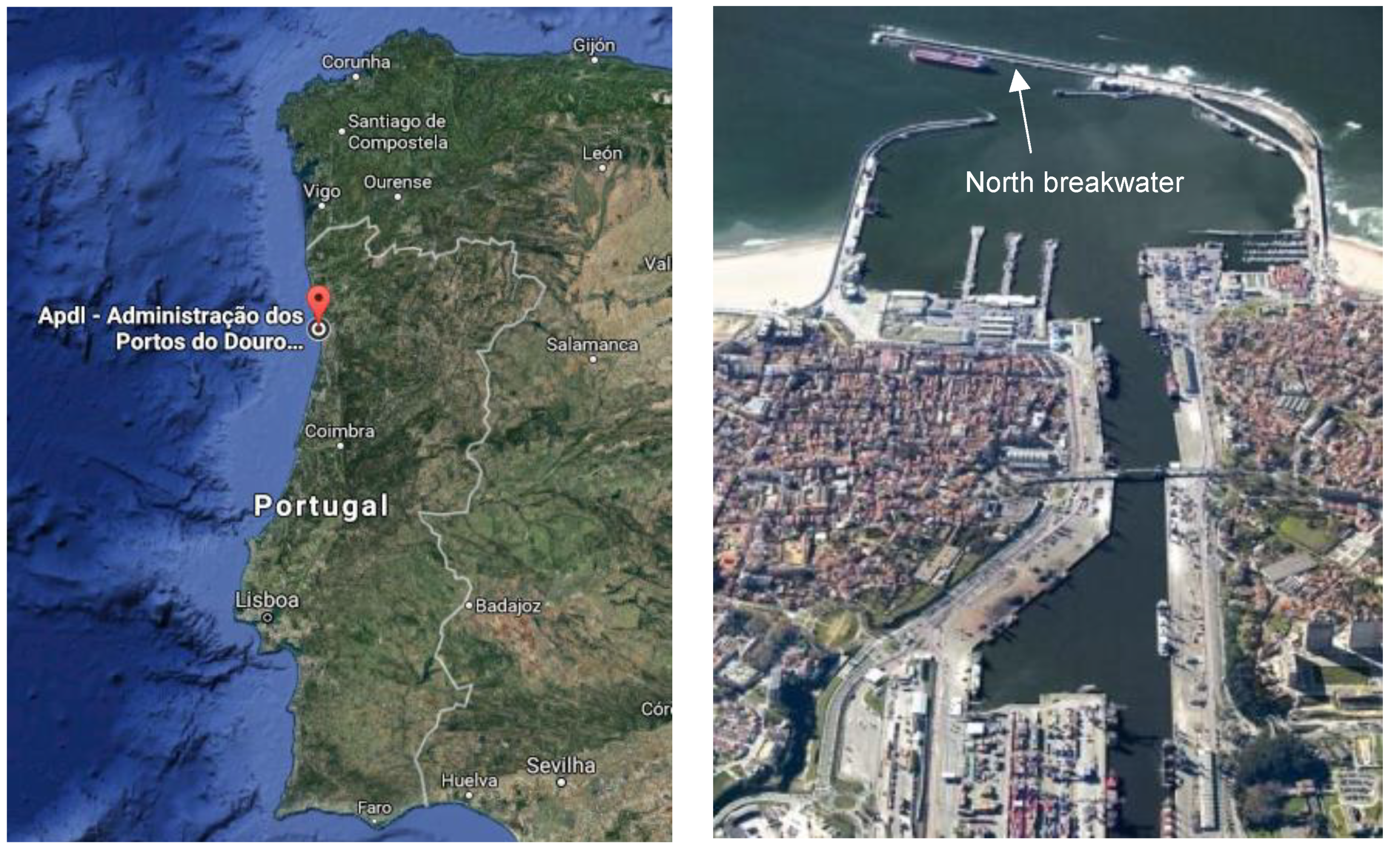
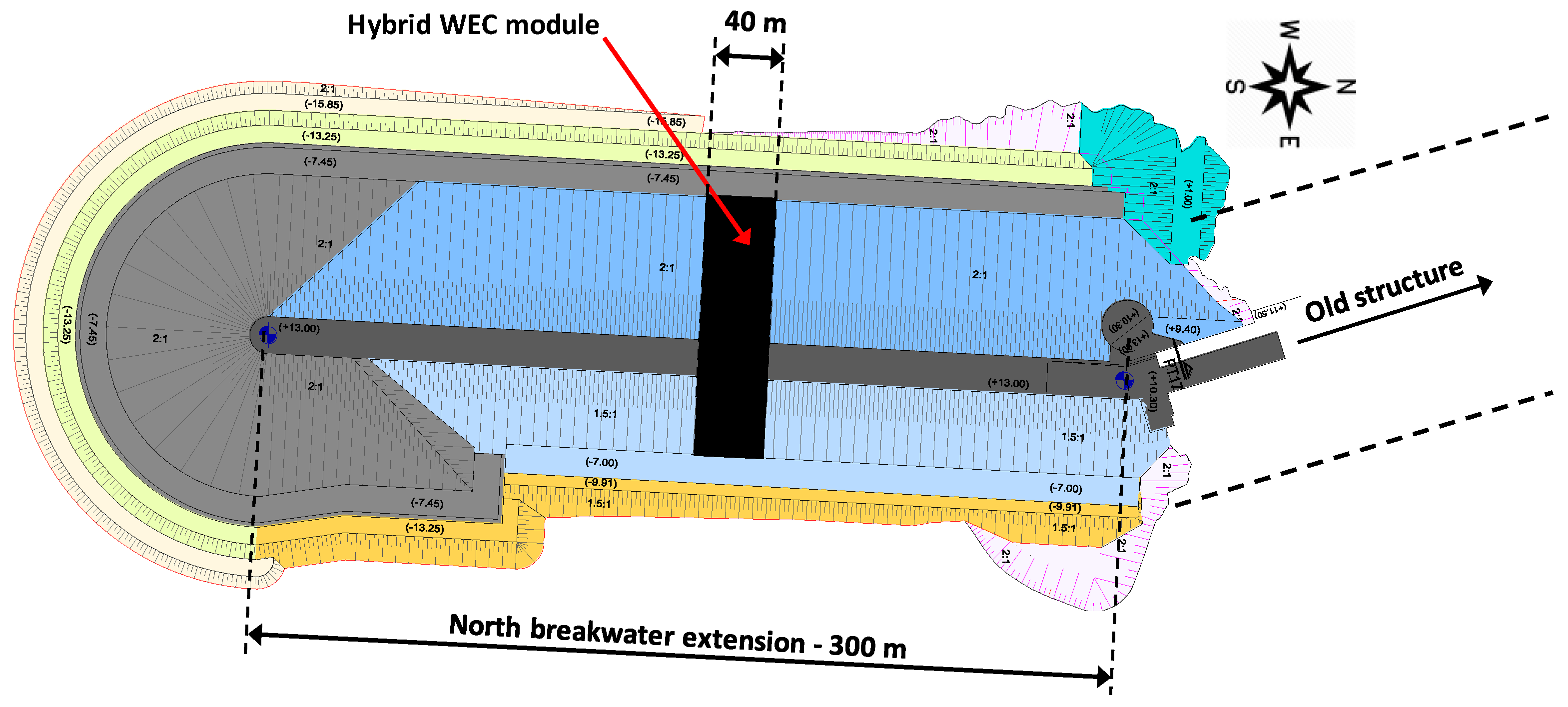
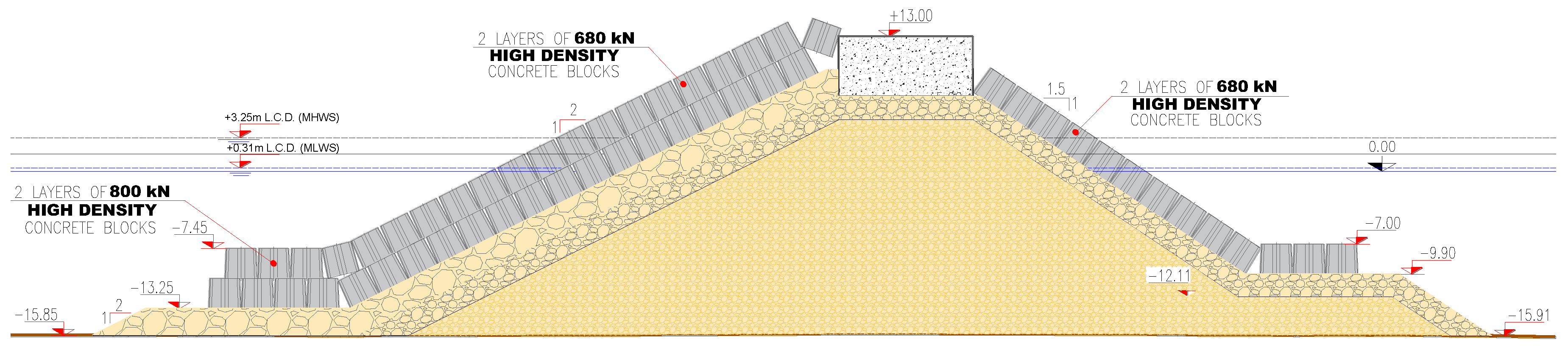
2. Case Study Characterization

The SE@PORTS project has two case studies: the Port of Leixões, in Portugal, and the Port of Las Palmas, in Spain. The hybrid concept experimentally studied in this paper was developed having as reference the characteristics of the structure proposed for the extension of the north breakwater of the Port of Leixões.
The Port of Leixões is located at the NW coast of Portugal at a latitude of 41°11′ North and a longitude of 8°42′ West, and nearly 4 km North of the mouth of Douro River, in Porto. With the biggest harbor infrastructure in the North of Portugal, this port has undergone important changes since its construction in 1890. Nowadays, innermost facilities are protected by the North breakwater which spans more than 2000 m, Figure 1.
Currently, one of the most relevant projected interventions in the Port of Leixões is the extension of the North breakwater. The proposed solution is intended to not only provide enhanced sheltering in the harbor basin, but also an improvement of the conditions for the ships entering the port. This structure, due to its characteristics and exposure to ocean waves, presents favorable conditions for the implementation of the hybrid WEC being developed in the scope of the SE@PORTS project. Hence it was considered as case-study and used as reference in the development of the hybrid WEC module.
In the preliminary design, two-extension lengths were considered (200 m and 300 m), with two different orientations: one aligned with the existing north breakwater and the other oblique to it and with an orientation almost north–south [25]. Simulations for the ship maneuverability on approach to the port favored the 300 m extension with the non-aligned orientation. Figure 2 presents the provisional layout of the structure as well as the location considered for the implantation of the hybrid WEC module.
The bathymetric surveys nearby the implantation site show that water depths reach about 18 m (CD) at the head of the north breakwater extension. The design of the breakwater extension resulted in a rubble-mound structure with an armor layer made of Antifer blocks produced with high-density concrete [26]. The superstructure, the armor layer, and the cross section characteristics are presented in Figure 3.
The Port of Leixões location implies that it is subjected to very severe wave conditions. The most frequent offshore significant wave heights are between 1 and 2 m, with about 70% of the occurrences ranging between 1 and 3 m. However, maximum significant wave heights may surpass 8 m. The peak wave periods are commonly in the range of 6 to 12 s (about 84% of occurrence frequency) and the maximum value is around 20 s [27].
The local wave conditions, for a location in front of the North breakwater, were determined from the offshore wave climate using the SWAN (simulating waves nearshore) numerical model [27]. It was concluded that the significant wave heights range between 0.0 and 7.4 m (1.6 m in average) and that most of the records have significant wave heights bellow 4.0 m. The mean wave periods range between 3.2 and 15.3 s (7.0 s in average). The mean wave direction is between 182° and 337° (approx. between W and NNW). At site, tides are of the semi-diurnal type with amplitudes ranging between 2 and 4 m [27].
It is expected that the Port of Leixões will continue to improve and to enlarge its facilities in the near future to accommodate larger ships and efficiently handle increasing quantities of cargo. The development of a port is frequently linked to energy consumption. From 2014 to 2016, for instance, the total energy consumption increased by 14.8% to 29 015 MWh, representing the electrical energy share (low and medium voltage consumption) 49.6% of that amount [28].
The sustainable development of the port activities requires increasing the share of clean and renewable energy sources. The integration of innovative hybrid WECs in port sheltering structures should contribute to increase the local renewable energy production and transforming ports in more sustainable and environmentally friendly infrastructures.
It is worth mentioning that the hybrid WEC module being developed in the present study might be integrated in breakwaters either during the construction phase or, eventually, at a later stage, for instance, in a rehabilitation project.

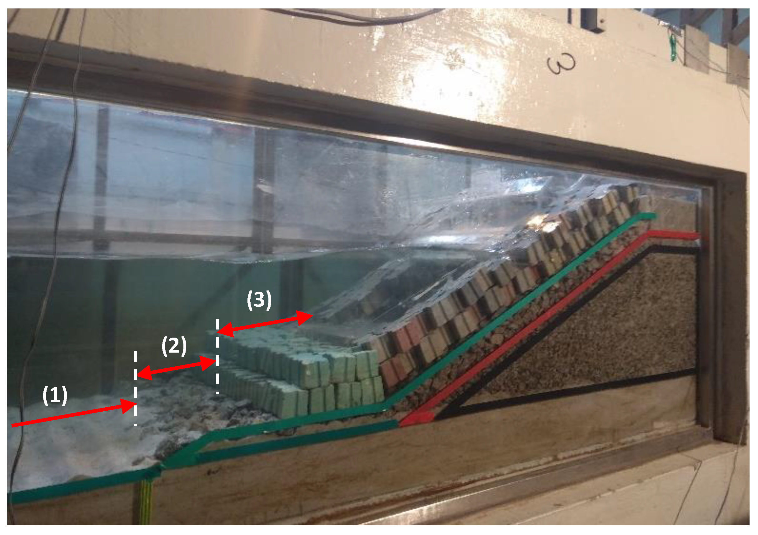
3. Experimental Study

3.1. Introduction

The hybrid WEC module developed consists in the combination of an OWC and an OWEC. The OWEC consists of a number of reservoirs one over each other (above the mean water level), which store temporarily the overtopped water of incident waves. Low-head multi-stage hydraulic turbines are then used to convert the potential energy of the stored water into electric power [22,23,29].
The OWC is composed of a semi-submerged chamber open to the sea below, which keeps a trapped air pocket above a water column. The action of waves forces the column to act like a piston, moving up and down, forcing the air out of the chamber and back into it again. This continuous bidirectional stream of high-velocity air passes through a turbine that converts it into energy [19,20,30].
The design of the hybrid WEC resulted from the combination of efforts between FEUP and INEGI, and was made using numerical tools. The WOPSim 2.0 software [31] was used to optimize the geometry of the OWEC, namely the number of reservoirs and their crest level as well as the slope angle of the approach ramp. The OWC device was designed and its resonance frequency adjusted with the assistance of the CFD code ANSYS Fluent [32].

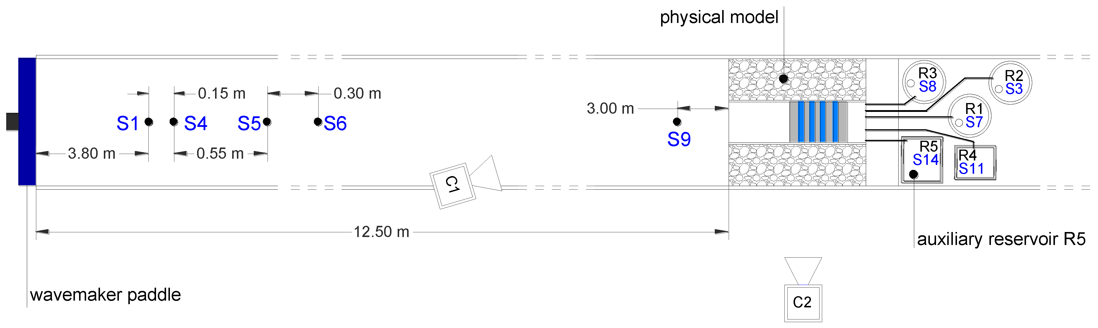
3.2. Equipment and Experimental Facility

The experimental study on the hybrid WEC solution for the Port of Leixões was conducted at the Hydraulics Laboratory of the Hydraulics, Water Resources and Environment Division of the Faculty of Engineering of the University of Porto (FEUP), Portugal. This experimental facility has a wave basin which spans 28.0 m in length, 12.0 m in width, and 1.2 m in depth, and is equipped with a multi-element piston-type wave generation system (HR Wallingford, Oxfordshire, UK). The wave reflections are controlled by the rubble-mound dissipative beach and a dynamic wave absorption system integrated in the wavemaker.
Based on similar studies on the OWEC (e.g., [33]) and the OWC (e.g., [34]) technologies, and considering the physical limitations of the wave basin, the 2D physical model of the hybrid module was conceived and built at a 1/50 geometrical scale. Mitigation of scale effects associated with an incomplete hydraulic similitude was also taken into account as well as the logistical challenges inherent to incorporating an OWC and an OWEC hybrid WEC in a geometrically limited and already defined breakwater structure.
The equipment used in this experimental study included: resistive wave gauges (HR Wallingford, Oxfordshire, UK), as to acquire the time series of the water free surface elevation (including in the OWC chamber) and to perform the wave reflection analysis; a pressure sensor (Honeywell, Golden Valley, MN, USA), in order to measure the pressure variations inside the OWC; auxiliary reservoirs equipped with pumps (Resun, Longgang, Shenzhen, China) to quantify the intake overtopping volumes; and a 2D bed profiler (HR Wallingford, Oxfordshire, UK), deployed with the intent of monitoring any potential scouring phenomena at the toe of the breakwater.
The 2D physical model was built and tested in a 0.80 m wide channel materialized inside the wave basin. Figure 4 presents the experimental setup, showing the location of the wave probes, the physical model of the breakwater with the hybrid WEC integrated and the auxiliary reservoirs (R1, R2, R3, R4, and R5) used to measure the overtopping volumes. R1–R4 were linked to the OWEC main reservoirs and R5 was used to measure the overtopping over the crest of the breakwater structure.
A total of eleven resistive probes were used in the experiments to measure the water free surface elevation: five to monitor water levels inside the auxiliary reservoirs (S3, S7, S8, S11, and S14), five to measure the water free surface elevation in the wave channel and one inside the OWC to monitor the dynamics of the oscillating water column. From those, four aligned wave gauges were allocated to the determination of the incident wave conditions (S1, S4, S5, and S6). One probe was located closer to the model to measure the water free surface elevation just in front of the structure (S9). Two video cameras (C1 and C2) were used to record the experimental tests from different perspectives, Figure 4. The system designed to measure the volume of overtopped water during the tests, composed of several pumps and gauge levels, is described later.

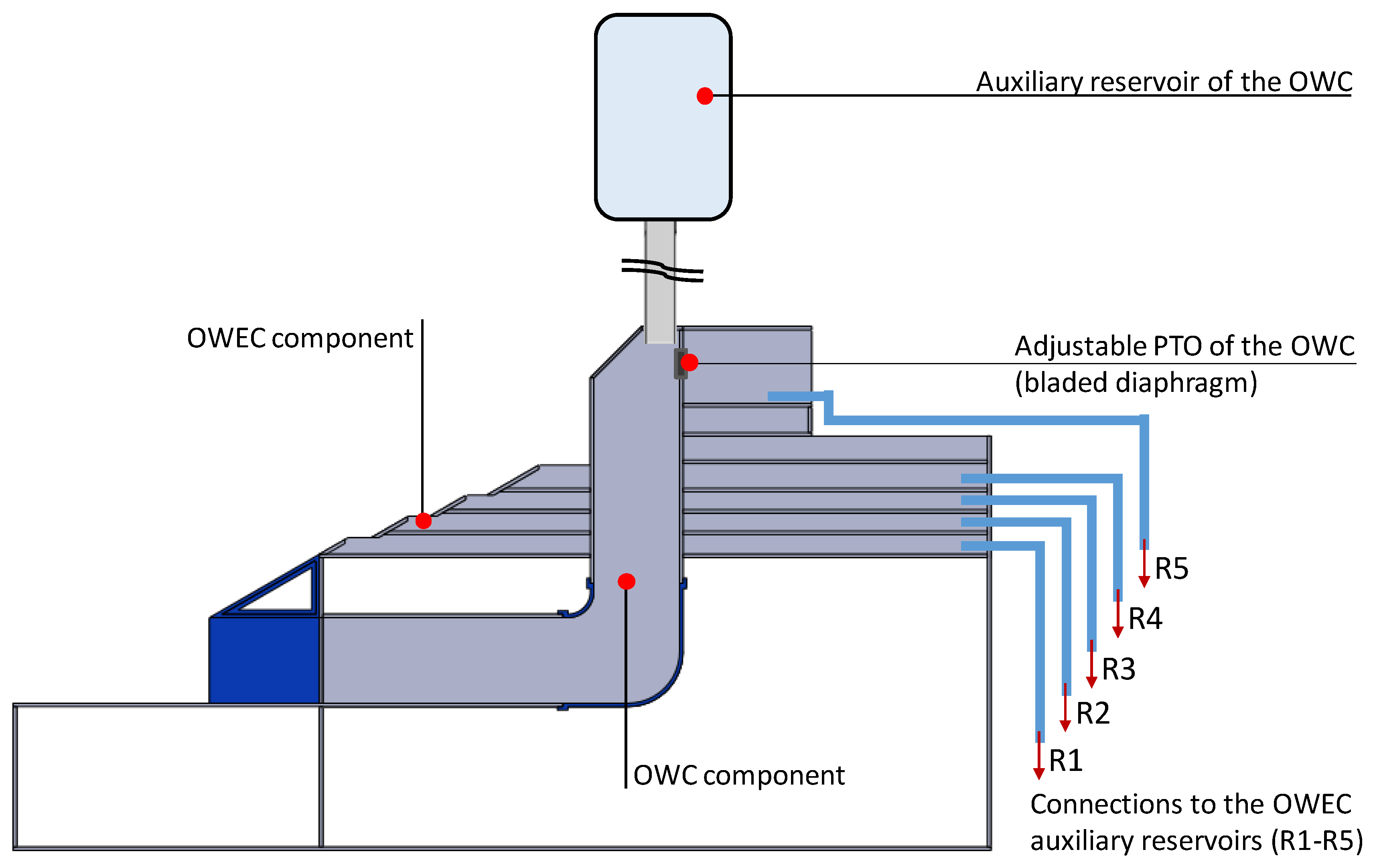
3.3. Hybrid WEC Physical Model

The design and construction of the hybrid WEC module was performed to allow for a comprehensive assessment of its hydraulic efficiency and performance, including for extreme wave conditions, as these are vital to increase the TRL of the hybrid concept and develop it aimed at integrating a full-scale prototype on a real harbor breakwater, for example the north breakwater extension of the Port of Leixões, which is used in this work as reference structure.
A 40 m wide cross section of the Leixões north breakwater extension (full-scale, Figure 2) was reproduced in the experimental facility on a geometric scale of 1/50, Figure 4. Since the hybrid WEC module is 20 m wide (0.40 m at model scale), the breakwater cross-section (Figure 3) was reproduced on both sides of this central module, completing the 0.80 m of the wave channel, Figure 4.
The OWEC system was comprised of four main reservoirs, with the crest levels at 0.75, 2.00, 3.25, and 5.00 m relative to the mean sea level (MSL) at full-scale, from lowest to highest, respectively, and also an intake reservoir at the top of the structure, to collect water overtopping the breakwater crest, Figure 5.
All OWEC’s reservoirs were 20 m wide (at full-scale), in accordance to the dimensions of the hybrid WEC module. Since the capacity of those main reservoirs was not enough to store the entire overtopped volumes during the experimental tests, an overtopping storage-measurement system was installed at the rear side of the physical model, Figure 4. Therefore, each OWEC’s reservoir was connected by a hose to an auxiliary reservoir equipped with a hydraulic pump and a resistive wave gauge to measure the time series of the water level inside each individual reservoir, Figure 6, as in [33]. This separation of overtopped volumes is required since the total head available is different for each individual OWEC reservoir (R1, R2, R3, and R4).
The resistive gauges were also used to control pumps’ operation (i.e., the start and stop). Hence, when the water free surface reached a fixed superior level inside a certain auxiliary reservoir, the corresponding pump was activated and it only stopped when the minimum level was reached. This measurement system is based on the determination of the operation time of the hydraulic pumps used to emptying the auxiliary reservoirs and also on the assumption that the pumps’ flow rate is approximately constant over that period (this methodology was verified in preliminary tests of the measurement system for the range of operation expected in the experimental tests), [33].
An angle of 30° (relative to the horizontal plan) was chosen for the overtopping ramps, for all four OWEC’s reservoir fronts, with the intent of ensuring the occurrence of slightly breaking surging waves and to minimize changes to the initial slope of the breakwater extension project.
The OWC component of the hybrid WEC module included, at the front, a submerged water intake (Figure 5) that had to be designed in order to both present a resonant period of the chamber in accordance to the local wave climate, and prevent any air intake for the test conditions combining the low-tide water level with high significant wave heights. The OWC was also connected to an auxiliary reservoir to have a better reproduction of the air compressibility inside the oscillating water column, Figure 6. Since the volume of air inside the OWC in still water conditions depends on the water level, the volume of air inside the OWC auxiliary reservoir was controlled, adding or removing water from it. This approach was based on the method described by [35].
Concerning the reproduction of the power take off (PTO), it was decided that a standard bi-radial turbine would be adopted in the prototype. Therefore, the air flow rate is considered to be proportional to the square root of the pressure [36]. A bladed diaphragm from a photographic camera was used with the intent of obtaining a similar relationship between the air “flow rate” and the “pressure”, by adjusting the diameter of the aperture. Up to eight diameters were tested during the experiments, ranging from 15 to 2.5 mm, in order to determine the best one in terms of OWC energy production. The control of the diaphragm aperture was done, in real time, using an Arduino Nano board and Arduino IDE software. Eight different damping levels were considered for the PTO of the OWC, which correspond to the different diameters of the diaphragm aperture: A02#, A03#, A04#, A05#, A06#, A07#, A08#, and A09#. Figure 6 shows the location of the adjustable PTO of the OWC in the hybrid WEC module.
In addition, three different geometries were considered for the water intake of the OWC module of the hybrid WEC, Figure 7. Nevertheless, only one was selected to be used in the assessment of the effects of the hybrid WEC integration on the breakwater (geometry C). The selection criteria of the OWC geometry is described in Section 4.1.
It should also be noted that the bathymetry was reproduced along the 2D wave channel, from the toe of the structure to a distance of about 12.50 m, close to the wave generating system, Figure 4, following a slope of 0.63º in the direction of the wave propagation. This allows reproducing nearshore phenomena such as the wave shoaling and to analyze if some scour phenomena develops in front of the physical model.

3.4. Testing Program

The testing plan was divided in three test series (TS), with the following characteristics and objectives:
  • TS1—analysis of the stability and functionality of the breakwater without the hybrid WEC module;
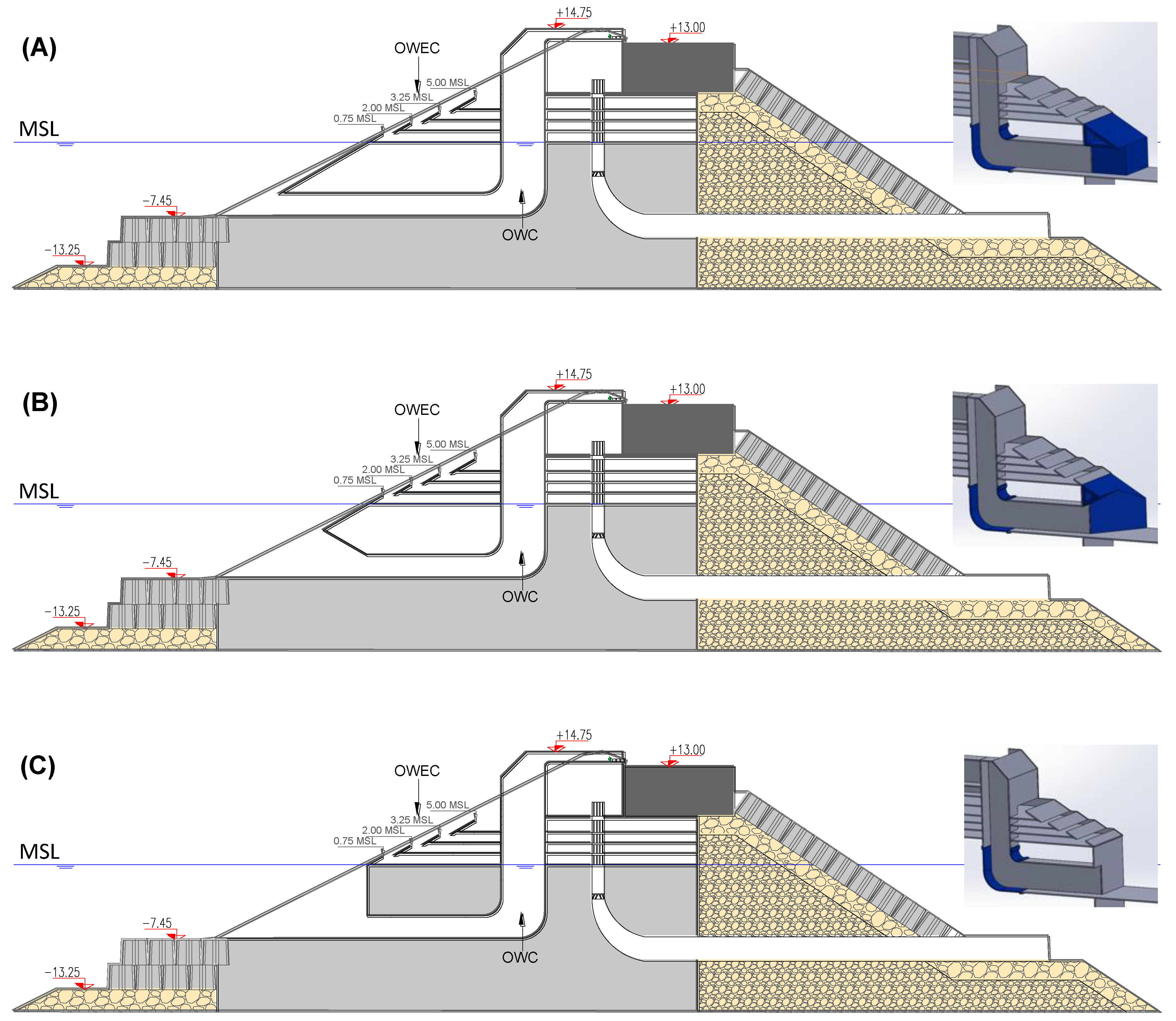
  • TS2—analysis of the performance of the different configurations of the hybrid WEC integrated in the breakwater (Figure 7);
  • TS3—analysis of the stability and functionality of the breakwater with the hybrid WEC module integrated in the structure.
In TS2, different setups were considered for the hybrid WEC, namely in terms of entrance to the OWC (Figure 7) and characteristics of its PTO system, in order to select the most suitable one for the case-study application. The present work is focused mainly in the impact of the hybrid WEC module on the breakwater, namely in terms of overtopping volumes and stability of the toe berm blocks that support the main armor layer (i.e., the structure foundation). In spite of that, the selection process of the OWC geometry is also presented, which was based on the performance of the OWC, both in terms of efficiency and resonance periods. The physical model of the breakwater with and without the hybrid WEC module integrated is presented in Figure 8.
The experimental tests of TS2 used to select the best OWC geometry were carried out for regular waves characterized by a wave height of 1 m and the following wave periods: 6, 7, 8, 9, 10, 11, 12, 13, and 14 s. Each individual test included about 100 waves. The water level corresponding to the mean sea level was considered in these tests.
The experimental tests of TS1 and TS3 were carried out only with irregular long crested waves that correspond to extreme wave conditions. The irregular sea states were defined by a JONSWAP spectrum (peak enhancement factor of 3.3) and reproduced using the filtered white noise technique [37]. In addition, the same temporal sequence of about 1000 waves was used in the tests carried out for each peak wave period, so as to allow a deterministic comparison of the results. To note that the more extreme sea states (i.e., highest significant wave heights and peak wave periods) selected for this study were defined taking into account both the wave breaking phenomena and the physical limitations of the wavemaker, which was working with the active absorption module on to compensate wave reflection.
The wave conditions considered in test series TS1 and TS3 are presented in Table 1 (in full-scale values), characterized by its significant wave height (planned or reference value), H S , and peak wave period, T P . Two different water levels were considered in these tests: the mean high water springs (MHWS) and the mean low water springs (MLWS), 1.58 m above the MSL and 1.36 m below the MSL, respectively. The selected wave conditions were calibrated before the beginning of the tests.

4. Experimental results

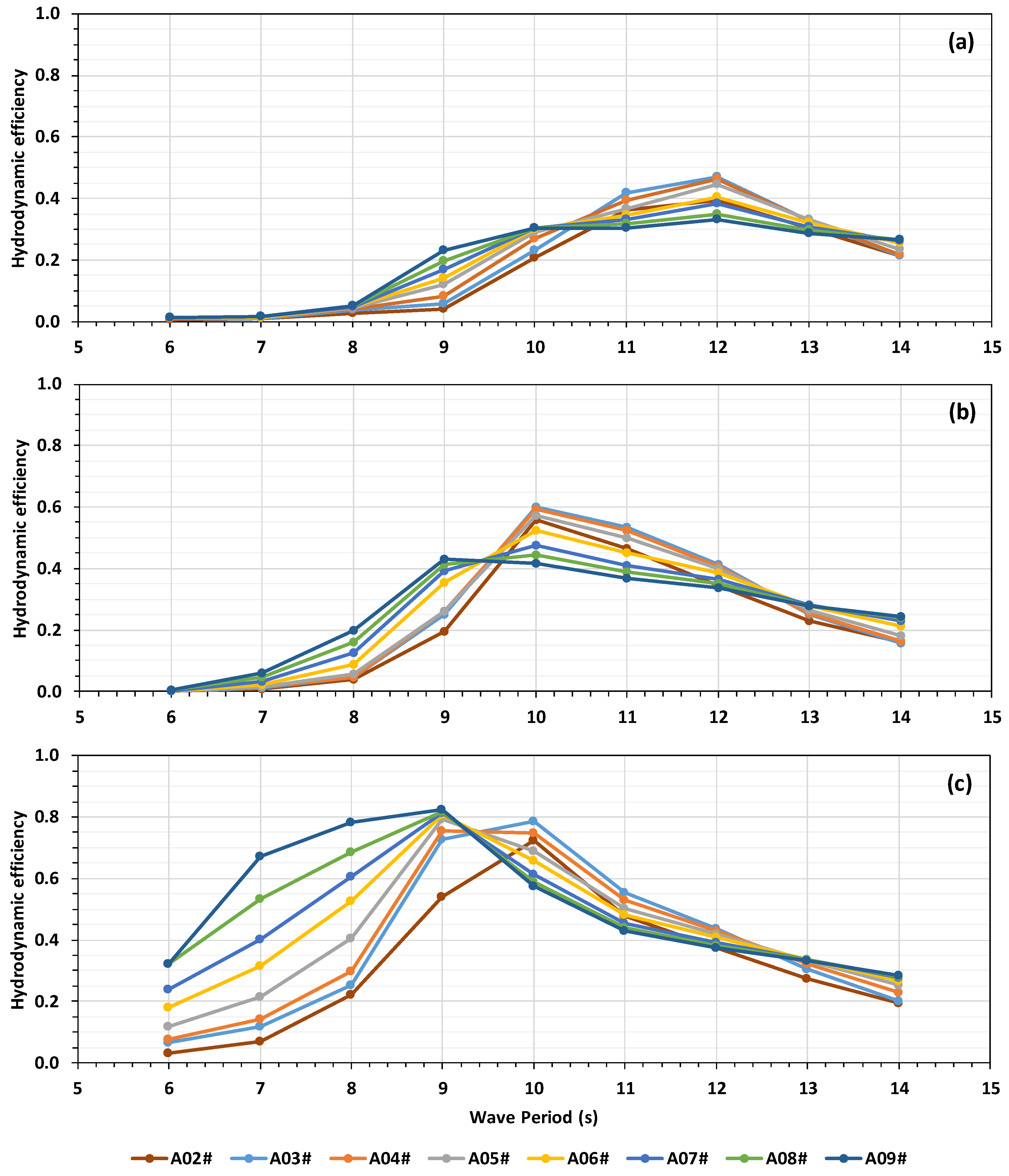
4.1. Selection of the OWC Geometry

The OWC geometry to be used in the tests of TS3 was selected based on the performance of the three alternative geometries in the regular wave tests carried out in TS2, both in terms of hydrodynamic efficiency and range of resonance periods of the system.
The instantaneous wave power absorbed by the OWC was calculated based on the values of the water free surface elevation inside the chamber and the chamber air pressure [38],
P = A d η d t p
where A represents the cross-sectional area of the free surface in the chamber, η the instantaneous water free surface elevation in the chamber, t the time, and p the instantaneous air pressure in the chamber.
The time-average energy flux of the incident waves per meter of wave front, according to linear wave theory, is given by,
P W = 1 2 ρ g ξ 2 C g
where ρ represents the sea water density, g the acceleration of gravity, ξ the incident wave amplitude, and C g the group velocity of the incident wave defined as,
C g = 1 2 ω k ( 1 + 2 k h sinh   2 k h )
where k   represents the wave number, ω the angular frequency and h the local water depth.
The hydrodynamic efficiency of the OWC, i.e., the relative capture width, was determined as,
C W = P ¯ P W B
where P ¯   represents the absorbed power averaged over the test duration and B the width of the OWC.
The hydrodynamic efficiency of the three tested OWC geometries (Figure 7), for the different PTO damping values considered (from A02# to A09#), is presented Figure 9.
It can be concluded that geometry C presents the best hydrodynamic efficiencies for the range of wave periods typical of the case study location (Fortes et al., 2017) and similar results to the others for wave periods higher than 11 s. Based on this conclusion, geometry C was selected to be characterized in more detail in TS2 (results not presented here). In addition, the tests of TS3 were only carried out for that geometry of the OWC.

4.2. Impact of the Hybrid WEC Module in the Breakwater

The test conditions considered in TS1 and TS3 (Table 1) correspond to extreme sea states defined to evaluate the behavior of the rubble-mound breakwater with and without the hybrid WEC integrated. The analysis carried out was focused on the:
  • behavior of the breakwater with regard to wave reflection;
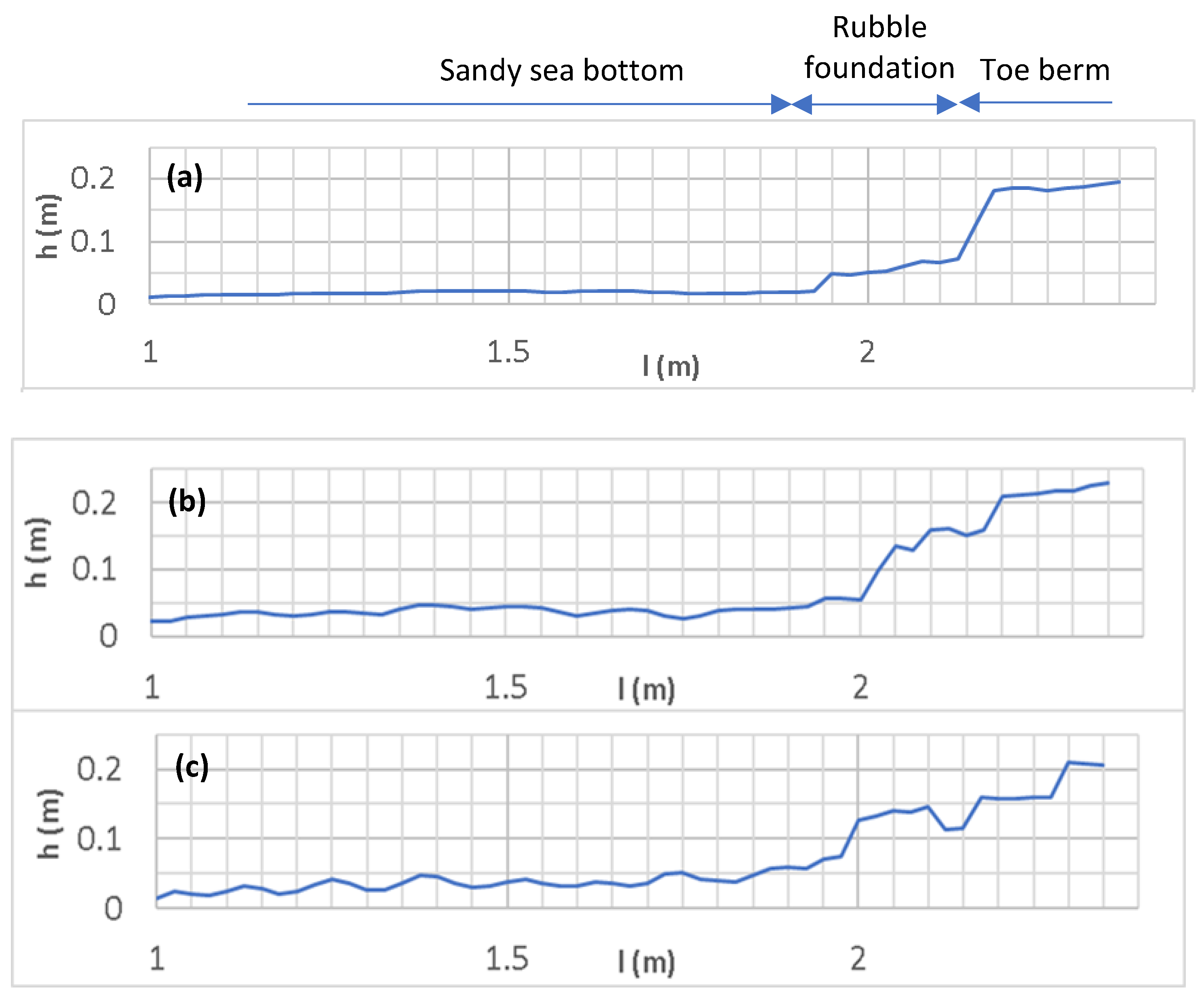
  • scour development in front of the structure toe;
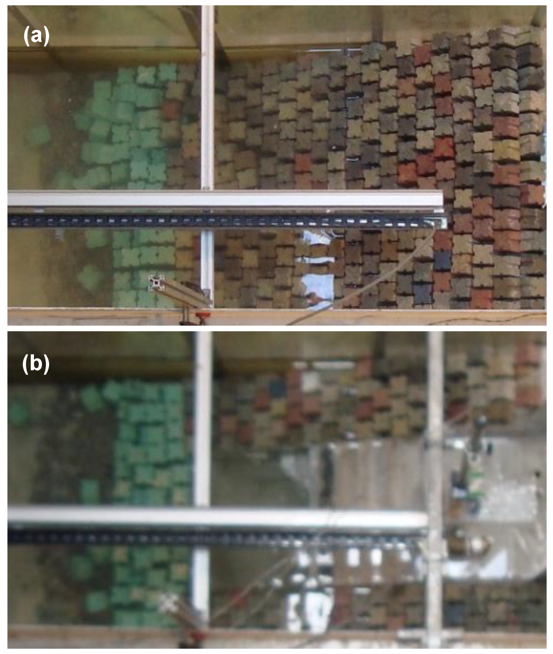
  • number of blocks displaced from the toe berm;
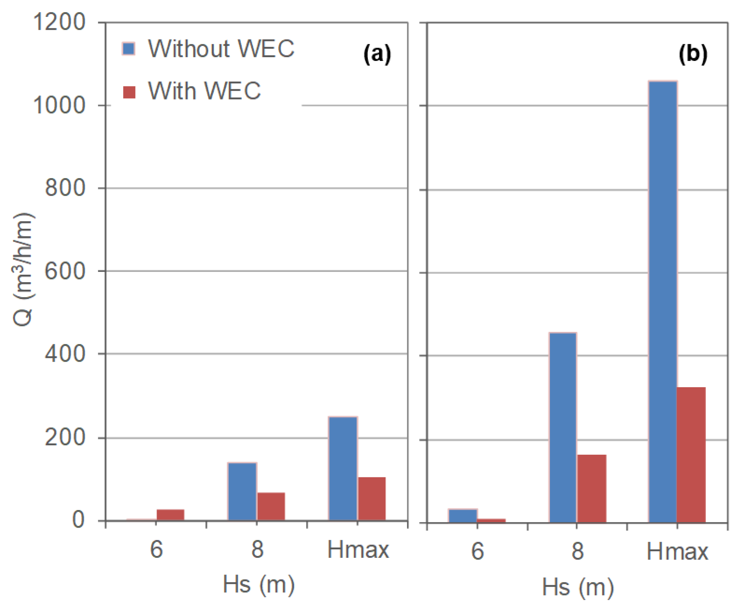
  • mean overtopping flow rate over the crest of the structure.
The reflection analysis was carried out using a script based on a development of the least squares method proposed by [39], which uses simultaneous records of the water free surface elevations measured by four aligned wave gauges (S1, S4, S5, and S6 in Figure 4). This analysis allowed for the determination of the incident significant wave height, H S , i , the significant reflected wave height, H S , R , and the reflection coefficient, C R , defined as
C R = H S , R H S , i .
The results of the reflection analysis are presented in Table 2 for the conditions tested in TS1 and TS3. The local significant wave height in front of the breakwater ( H S , l ) was determined based on the free surface elevation records of S9 (Figure 4).
It can be concluded that the behavior of the tested rubble-mound breakwater, with respect to the wave reflection, is not significantly affected with the integration of the hybrid WEC module in the structure. In fact, only a slight increase of C R values was observed: its range of variation is (0.28–0.36) for TS1 and (0.32–0.37) for TS2, Table 2. It can also be observed that the values of C R are slightly higher for the higher water level (MHWS).
The significant wave height values are consistently higher in front of the structure (S9, Figure 4) due to the shoaling phenomena in the foreshore and, eventually, the pattern of superposition of incident and reflected waves created at that location.
To analyze the bathymetry variation in front of the structure, 2D profiles were measured before and after each test series, which comprised six sea states of increasing significant wave height and peak wave period (Table 2). In total, in each test series, the rubble-mound breakwater was submitted to approximately 6000 waves (6 × 1000 waves), which correspond to about 26 h of testing time in the prototype.
Figure 10 presents the bathymetric profiles measured before and after the tests of TS1 and TS3, corresponding to the central alignment of the wave channel (Figure 4). These profiles contain: the sandy sea bottom in front of the structure, the rubble foundation of the breakwater and also its toe berm, which gives support to the main armor layer and is composed of two rows of Antifer blocks. Figure 11 presents the hybrid WEC module integrated in the breakwater allowing the identification of the three areas mentioned.
Although some differences can be clearly observed in the bathymetric profiles measured after the 6000 waves, Figure 10, there was no evidence of scour phenomena development at the toe of the rubble-mound breakwater for the conditions tested, either with or without the hybrid WEC module installed. In fact, the most significant variations of the profile were observed at the toe berm of the breakwater, due to displacements of some Antifer blocks, which experienced movements essentially during the tests carried out for the most extreme sea state of each test series. In front of the toe berm, only the sand undulations (ripples) typical of this kind of test with mobile beds could be observed, as shown in Figure 11.
The damage in the armour layer and toe berm of the rubble-mound breakwater was visually analysed after TS1 and TS3, Figure 12. The majority of the displaced blocks are from the toe berm of the breakwater (green blocks) that experienced: rocking, displacements out of the toe berm and also sliding.
The number of units with a relevant displacement (i.e., more than a characteristic dimension of the Antifer blocks) was 25 in TS1 and 20 in TS3. Despite the limited number of conditions tested in this experimental work, it can be concluded that the integration of the hybrid WEC in the breakwater did not affected negatively the stability of the toe berm. It should be pointed out that no conclusions could be drawn about the stability of the armor layer blocks (breakwater slope), due to the so called ‘wall effects’, particularly when the hybrid WEC is introduced in the breakwater. However, it should be mentioned that in a real intervention (full-scale), it is expected that the armor layer blocks nearby the walls of the WEC module are solidarized with it by concrete casted in place.
It is also important to analyze if the integration of the hybrid WEC module in the breakwater has any relevant impact in the magnitude of overtopping events. Hence, the mean overtopping flow rates for TS1 and TS3, and for the two tested water levels, were estimated based on the overtopped water collected in the reservoir R5 (Figure 6) and the results presented in Figure 13. It can be observed that overtopping flow rates over the crest of the breakwater are much higher for the higher tide level (MHWS), as expected.
In addition, the results show that the integration of the hybrid WEC module on the structure has a positive effect in terms of overtopping, leading, in general, to a reduction of the mean flow rates, Figure 13. The exception to that conclusion, observed in the results obtained for the smaller significant wave height tested ( H S = 6 m), was attributed to the usual uncertainty in the prediction of overtopping discharges [40], especially high for very low discharge data, which typically show a wider variability.
The conclusions obtained are important since they demonstrate that the integration of WECs in harbor breakwaters is possible without compromising the stability or the functionality of these key structures.

5. Conclusions

The influence of the integration of a hybrid WEC module on the stability and functionality of a rubble-mound breakwater was assessed in an experimental study carried out on a geometric scale of 1/50, seeking to fill the gap in existent knowledge on the subject. The rubble-mound structure proposed for the extension of the North breakwater of the Port of Leixões was used as case-study.
The experimental results obtained allowed to concluded that the integration of the hybrid WEC module in the breakwater does not affect negatively the stability of the toe berm blocks and does not contribute to the development of scour phenomena in front of the structure. Furthermore, the hybrid WEC module seems to reduce, significantly, the mean overtopping flow rate of the breakwater, thus improving its functional performance. The behavior of the breakwater with regard to wave reflection was not significantly affected, although a small increase of the reflection coefficient was noticed in the tests with the hybrid WEC module. Additional tests, for new conditions, are needed to confirm and extend the obtained results and conclusions, which seem very favorable to the integration of this type of device on harbor breakwaters.

Author Contributions

The conceptualization and execution of the experimental test program resulted from the combination of efforts between FEUP and INEGI (all authors involved). The analysis of the data related to the stability and functional performance of the breakwater was done by FEUP (D.C.; F.T.-P.; P.R.-S.; T.C.) while the selection of the best performing OWC geometry was the result of the analysis done by INEGI (F.B.; F.F.; T.M.). The funding acquisition was the responsibility of the senior researchers of the R&D project (F.T.-P.; P.R.-S.; T.M.).

Funding

This research was funded by the OCEANERA-NET project SE@PORTS—Sustainable Energy at Sea PORTS—with the references OCEANERA/0004/2016 and OCEANERA/0003/2016, under the frame of FCT, the Portuguese Foundation for Science and Technology.

Acknowledgments

The authors are in debt to LNEC (Laboratório Nacional de Engenharia Civil), which lent the Antifer units used to materialize the armour layer of the reference breakwater model, and to the Port Authority of Douro, Leixões, and Viana do Castelo, for all the information provided to characterize the case study. Prof. João Henriques (from Instituto Superior Técnico) provided important contributions to the testing and control of the PTO system used in the OWC module.

Conflicts of Interest

The authors declare no conflict of interest.

References

  1. Kost, C.; Mayer, J.; Thomsen, J.; Hartmann, N.; Senkpiel, C.; Philipps, S.; Nold, S.; Lude, S.; Saad, N.; Schlegl, T. Levelized Cost of Electricity Renewable Energy Technologies; Fraunhofer Institut for Solar Energy Systems ISE: Freiburg, Germany, 2013. [Google Scholar]
  2. WECouncil. World Energy Resources 2016, 24th ed.; World Energy Resources, Ed.; World Energy Council: London, UK, 2016. [Google Scholar]
  3. Riefolo, L.; Lanfredi, C.; Azzellino, A.; Vicinanza, D. Environmental Impact Assessment of Wave Energy Converters: A Review. In Proceedings of the International Conference on Applied Coastal Research SCACR, Florence, Italy, 28 September–1 October 2015. [Google Scholar]
  4. Coe, R.G.; Neary, V.S. Review of Methods for Modeling Wave Energy Converter Survival in Extreme Sea States. In Proceedings of the METS2014 2nd Marine Energy Technology Symposium, Seattle, WA, USA, 15–18 April 2014. [Google Scholar]
  5. Gunn, K.; Stock-Williams, C. Quantifying the global wave power resource. Renew. Energy 2012, 44, 296–304. [Google Scholar] [CrossRef]
  6. Rosa-Santos, P.; Clemente, D.; Taveira-Pinto, F. Marine Renewable Energy: Opportunities Challenges and Potential for Integration in Aquaculture Farms. Int. J. Oceanogr. Aquac. 2018, 2, 000141. [Google Scholar]
  7. Bergillos, R.J.; López-Ruiz, A.; Medina-López, E.; Moñino, A.; Ortega-Sánchez, M. The role of wave energy converter farms on coastal protection in eroding deltas, Guadalfeo, Southern Spain. J. Clean. Prod. 2018, 171, 356–367. [Google Scholar] [CrossRef]
  8. Contestabile, P.; Vicinanza, D. Coastal Defence Integrating Wave-Energy-Based Desalination: A Case Study in Madagascar. J. Mar. Sci. Eng. 2018, 6, 64. [Google Scholar] [CrossRef]
  9. Puig, M.; Michail, A.; Wooldridge, C.; Darbra, R.M. Benchmark dynamics in the environmental performance of ports. Mar. Pollut. Bull. 2017, 121, 111–119. [Google Scholar] [CrossRef] [PubMed]
  10. Langen, P.; Turró, M.; Fontanet, M.; Caballé, J. The Infrastructure Investment Needs and Financing Challenge of European Ports; Port Investments Study 2018; European Seaports Organisation (ESPO): Brussels, Belgium, 2018; p. 94. [Google Scholar]
  11. Vicinanza, D.; Margheritini, L.; Kofoed, J.P.; Buccino, M. The SSG Wave Energy Converter: Performance, Status and Recent Developments. Energies 2012, 5, 193–226. [Google Scholar] [CrossRef] [Green Version]
  12. Chatzigiannakou, M.A.; Dolguntseva, I.; Leijon, M. Offshore Deployments of Wave Energy Converters by Seabased Industry AB. J. Mar. Sci. Eng. 2017, 5, 15. [Google Scholar] [CrossRef]
  13. Rémouit, F.; Chatzigiannakou, M.-A.; Bender, A.; Temiz, I.; Sundberg, J.; Engström, J. Deployment and Maintenance of Wave Energy Converters at the Lysekil Research Site: A comparative Study on the Use of Divers and Remotely-Operated Vehicles. J. Mar. Sci. Eng. 2018, 6, 39. [Google Scholar] [CrossRef]
  14. Taveira-Pinto, F.; Iglesias, G.; Rosa-Santos, P.; Deng, Z.D. Preface to Special Topic: Marine Renewable Energy. J. Renew. Sustain. Energy, 2015, 7, 061601. [Google Scholar] [CrossRef] [Green Version]
  15. Iuppa, C.; Contestabile, P.; Cavallaro, L.; Foti, E.; Vicinanza, D. Hydraulic performance of an innovative breakwater for overtopping wave energy conversion. Sustainability 2016, 8, 1226. [Google Scholar] [CrossRef]
  16. Contestabile, P.; Iuppa, C.; Di Lauro, E.; Cavallaro, L.; Andersen, T.L.; Vicinanza, D. Wave loadings acting on innovative rubble mound breakwater for overtopping wave energy conversion. Coast. Eng. 2017, 122, 60–74. [Google Scholar] [CrossRef]
  17. Sarmento, A.; Neumann, F.; Brito-Melo, A. Full-Scale WECs—Operational Experience: Oscillating Water Column—Pico Plant Ocean Wave Energy—Current Status and Future Perspectives; Springer Series in Green Energy and Technology; Springer: New York, NY, USA, 2008; ISBN 978-3-540-74894-6. [Google Scholar]
  18. Torre-Enciso, Y.; Marqués, J.; López de Aguileta, L.I. Mutriku. Lessons learnt. In Proceedings of the 3rd International Conference on Ocean Energy ICOE, Bilbao, Spain, 6 October 2010; ISBN 978-84-693-5467-4. [Google Scholar]
  19. Arena, F.; Romolo, A.; Malara, G.; Fiamma, V.; Laface, V. The first worldwide application at full-scale of the REWEC3 device in the port of civitavecchia: Initial energetic performances. Progress in Renewable Energies Offshore. In Proceedings of the RENEW 2016 2nd International Conference on Renewable Energies Offshore, Lisbon, Portugal, 24–26 October 2016; pp. 303–312. [Google Scholar]
  20. Arena, F.; Romolo, A.; Malara, G.; Fiamma, V.; Laface, V. The First Full Operative U-OWC Plants in the Port of Civitavecchia. In Proceedings of the ASME International Conference on Offshore Mechanics and Arctic Engineering, Trondheim, Norway, 25–30 June 2017; Volume 10. [Google Scholar]
  21. Falcão, A.; Henriques, J. Oscillating-water-column wave energy converters and air turbines: A review. Renew. Energy 2016, 85, 1391–1424. [Google Scholar] [CrossRef]
  22. Margheritini, L.; Vicinanza, D.; Frigaard, P. SSG wave energy converter: Design, reliability and hydraulic performance of an innovative overtopping device. Renew. Energy 2009, 34, 1371–1380. [Google Scholar] [CrossRef]
  23. Contestabile, P.; Vincenzo, F.; Di Lauro, E.; Vicinanza, D. Full-scale Prototype of an Overtopping Breakwater for Wave Energy Conversion. Coast. Eng. Proc. 2017, 1, 12. [Google Scholar] [CrossRef]
  24. Di Lauro, E.; Lara, J.L.; Maza, M.; Losada, I.J.; Contestabile, P.; Vicinanza, D. Stability analysis of a non-conventional breakwater for wave energy conversion. Coast. Eng. 2019, 145, 36–52. [Google Scholar] [CrossRef]
  25. IHRH. Projeto de Criação de um Novo Terminal para Contentores no porto de Leixões; Final Report; IHRH: Porto, Portugal, January 2013; Volume 15, 362p. (In Portuguese) [Google Scholar]
  26. Consulmar. Prolongamento do Quebramar Exterior e das Acessibilidades Marítimas do Porto de Leixões: Especificações para Ensaios 3D; Technical Report; Consulmar: Lisboa, Portugal, 2017. (In Portuguese) [Google Scholar]
  27. Capitão, R.; Pinheiro, L.; Fortes, J. Estudos em Modelo Físico e Numérico do Prolongamento do Quebramar Exterior e das Acessibilidades Marítimas do Porto de Leixões: Estudo I—Regimes de Agitação Marítima; Technical Report; LNEC: Lisboa, Portugal, April 2017. (In Portuguese) [Google Scholar]
  28. APDL. Relatório de Sustentabilidade 2016; Report N°11; Administração dos Portos de Douro, Leixões e Viana do Castelo, SA: Leça da Palmeira, Portugal, 2016. (In Portuguese) [Google Scholar]
  29. Margheritini, L.; Stratigaki, V.; Troch, P. Geometry Optimization of an Overtopping Wave Energy Device Implemented into the New Breakwater of the Hanstholm Port Expansion. In Proceedings of the 22nd International Offshore and Polar Engineering Conference (ISOPE), Rhodes, Greece, 17–22 June 2012; ISBN 978-1-880653-94–4. [Google Scholar]
  30. Torre-Enciso, Y.; Ortubia, I.; Lopez de Aguileta, L.I.; Marqués, J. Mutriku Wave Power Plant: From the thinking out to the reality. In Proceedings of the 8th European Wave and Tidal Energy Conference, Uppsala, Sweden, 7–10 September 2009; pp. 319–329. [Google Scholar]
  31. Meinert, P.; Giillin, L.; Kofoed, J.P. User Manual for WOPSim: Wave Overtopping Power Simulation; Report No. 44; Hydraulics and Coastal Engineering, Aalborg University: Aalborg, Denmark, 2008. [Google Scholar]
  32. ANSYS. ANSYS Fluent Theory Guide; Release 15.0; ANSYS: Canonsburg, PA, USA, 2013; 780p. [Google Scholar]
  33. Oliveira, P.; Taveira-Pinto, F.; Morais, T.; Rosa-Santos, P. Experimental evaluation of the effect of wave focusing walls on the performance of the Sea-wave Slot-cone Generator. Energy Convers. Manag. 2016, 110, 165–175. [Google Scholar] [CrossRef]
  34. Simonetti, I.; Cappietti, L.; Elsafti, H.; Oumeraci, H. Optimization of the geometry and the turbine induced damping for fixed detached and asymmetric OWC devices: A numerical study. Energy 2017, 139, 1197–1209. [Google Scholar] [CrossRef]
  35. Falcão, A.; Henriques, J. Model-prototype similarity of oscillating-water-column wave energy converters. Int. J. Mar. Energy 2014, 6, 18–34. [Google Scholar] [CrossRef]
  36. Falcão, A.; Gato, L.; Nunes, E. A novel radial self-rectifying air turbine for use in wave energy converters. Renew. Energy 2013, 50, 289–298. [Google Scholar] [CrossRef]
  37. Fryer, D.K.; Gilbert, G.; Wilkie, M.J. A Wave Spectrum Synthesizer. J. Hydraul. Res. 1973, 11, 193–204. [Google Scholar] [CrossRef]
  38. Ning, D.-Z.; Wang, R.-Q.; Zou, Q.; Teng, B. An experimental investigation of hydrodynamics of a fixed OWC Wave Energy Converter. Appl. Energy 2016, 168, 636–648. [Google Scholar] [CrossRef]
  39. Mansard, E.P.D.; Funke, E.R. The measurement of incident and reflected wave spectra using a least squares method. In Proceedings of the 17th International Conference on Coastal Engineering (ASCE), New York, NY, USA, 23–28 March 1980; Volume 1, pp. 154–172. [Google Scholar]
  40. Romano, A.; Bellotti, G.; Briganti, R.; Franco, L. Uncertainties in the physical modelling of the wave overtopping over a rubble mound breakwater: The role of the seeding number and of the test duration. Coast. Eng. 2015, 103, 15–21. [Google Scholar] [CrossRef]
Figure 1. Location of the Port of Leixões on the Iberian Peninsula (left, source: Google Maps) and an aerial view of the harbor entrance and its breakwaters (right, source: Port Authority of Douro, Leixões and Viana do Castelo).
Jmse 07 00033 g001
Figure 2. Provisional layout of the North breakwater extension (adapted from [26]).
Jmse 07 00033 g002
Figure 3. Provisional cross section of the north breakwater extension (adapted from [26]).
Jmse 07 00033 g003
Figure 4. Physical model setup in the channel built inside the wave basin of FEUP.
Jmse 07 00033 g004
Figure 5. 3D sketch of the hybrid wave energy converter.
Jmse 07 00033 g005
Figure 6. Hybrid WEC module: schematic representation of the cross-section.
Jmse 07 00033 g006
Figure 7. Geometries A, B, and C of the hybrid WEC tested (full-scale dimensions) and detail of OWC intake.
Jmse 07 00033 g007
Figure 8. Physical model without (left) and with (right) the hybrid WEC module (geometry B) integrated in the breakwater and before the experimental tests.
Jmse 07 00033 g008
Figure 9. Efficiency of the OWC for the three tested geometries considering the different PTO damping values: (a) geometry A, (b) geometry B, and (c) geometry C.
Jmse 07 00033 g009
Figure 10. Variation of the bathymetry in from of the breakwater toe: initial bathymetric profile (a) and profiles after test series TS1 (b) and TS3 (c).
Jmse 07 00033 g010
Figure 11. Physical model of the breakwater with the hybrid WEC module integrated: (1) sandy sea bottom, (2) rubble foundation, and (3) toe berm of the breakwater.
Jmse 07 00033 g011
Figure 12. Rubble-mound breakwater after the conclusion of the tests of TS1 (a) and TS3 (b).
Jmse 07 00033 g012
Figure 13. Mean overtopping flow rates obtained for TS1 and TS3, and for the two water levels: low tide—MLWS (a) and high tide—MHWS (b).
Jmse 07 00033 g013
Table 1. Wave conditions tested in TS1 and TS3.
H S   ( m ) T P   ( s ) Water Level
6.013
8.016MLWS
9.518
6.013
8.016MHWS
11.016
Table 2. Results of the reflection analysis with (TS3) and without (TS1) the hybrid WEC module.
Test Series H S   ( m ) T P   ( s ) Water Level H S , i   ( m ) H S , R   ( m ) CR H S , l
TS16.013 6.061.680.286.8
8.016MLWS7.562.340.319.0
9.518 9.112.890.328.9
6.013 5.871.810.316.8
8.016MHWS7.772.770.369.4
11.016 9.633.090.3210.6
TS36.013 5.951.930.326.9
8.016MLWS7.802.780.368.9
9.518 8.833.200.368.7
6.013 5.851.890.326.8
8.016MHWS8.102.990.378.8
11.016 9.853.500.3510.0

