Article

Overall Design and Performance Testing of a New Type of Marine Energy Storage Winch

1
Institute of Oceanology, Chinese Academy of Sciences, Qingdao 266071, China
2
University of Chinese Academy of Sciences, Beijing 100049, China
*
Author to whom correspondence should be addressed.
J. Mar. Sci. Eng. 2026, 14(9), 861; https://doi.org/10.3390/jmse14090861
Submission received: 16 April 2026 / Revised: 28 April 2026 / Accepted: 1 May 2026 / Published: 3 May 2026
(This article belongs to the Special Issue Advances in Ocean Observing Technology and System)

Abstract

High-resolution vertical profile observations of ocean environmental parameters are essential for investigating mesoscale ocean dynamic phenomena, such as internal waves, mesoscale eddies, and oceanic fronts. At present, vertical profile measurement in marine surveys mainly relies on shipborne winches to deploy and recover marine sensors, which entails high labor costs and considerable energy consumption. Unmanned observation platforms integrated with winch systems enable automatic sensor deployment and recovery, offering a viable approach to cutting observation costs. Nevertheless, inadequate energy supply remains a critical bottleneck restricting the large-scale popularization and application of such equipment. Accordingly, the development of high-efficiency winch systems tailored for unmanned autonomous observation platforms is of great engineering significance for facilitating long-term, continuous, and low-energy marine profile observation. This paper proposes a novel energy-saving winch with an embedded three-stage parallel nested energy storage structure for unmanned marine observation platforms. During operation, the coil spring energy storage system is charged during cable payout, and the stored elastic potential energy is released to assist motor driving in the cable retraction process. This auxiliary driving mode reduces motor power demand and improves the overall energy utilization efficiency of the platform. Experimental results demonstrate that, neglecting ocean current resistance, the proposed winch reduces energy consumption by 5% during cable payout and 21% during cable retraction. The overall energy consumption is decreased by 13% throughout a complete vertical profile measurement cycle. Under constrained and fixed energy supply conditions, this technology substantially enhances the sampling capability of unmanned marine platforms for ocean environmental monitoring. It further improves operational efficiency and extends continuous service time, providing key technical support for revealing ocean dynamic evolution and clarifying the formation and driving mechanisms of marine environmental phenomena.

1. Introduction

Marine scientific research heavily relies on multi-scale, long-term time-series marine environmental observation data. As an essential component of such data, vertical profile observation of oceanic parameters lays a fundamental foundation for elucidating ocean dynamic processes and characterizing ocean internal structures. It is also indispensable for investigating typical oceanographic phenomena, including internal solitary waves, submesoscale eddies, mesoscale eddies, and large-scale ocean circulation [1,2]. At present, the prevailing technical solution for ocean vertical profile monitoring adopts winch–cable systems to lower and recover detection equipment, so as to complete the acquisition of ocean profile data [3,4,5]. Nevertheless, conventional winches operate merely through the positive and negative rotation of motors to drive load lifting and lowering, resulting in high energy consumption and low operational efficiency. Such limitations make it difficult to satisfy the strict long-duration energy constraints of marine unmanned autonomous observation systems [6,7,8].
With the continuous advancement of marine observation technology toward unmanned and autonomous operation, traditional manually controlled research winches are gradually being phased out by automatic winch systems. Currently, automated winches have been widely applied to unmanned surface vehicles, large-scale ocean buoys, and seabed observation platforms [9,10]. Capable of autonomously deploying and recovering marine observation instruments to achieve vertical profiling, automatic winches support the long-term in situ monitoring of ocean environmental parameters. These systems not only substantially reduce the economic cost of oceanic expeditions and lower operational risks under harsh marine conditions but also facilitate data collection in extreme marine environments, providing critical technical support for further marine scientific exploration [11].
In the evolution of marine observation equipment, data storage and energy supply have long been recognized as two major bottlenecks restricting long-term continuous operation. Benefiting from the rapid development of high-capacity storage technology, the data storage limitation has been well resolved. In contrast, insufficient energy supply remains the dominant constraint that restricts the long-term autonomous observation capacity of unmanned marine platforms [12,13]. Manned research vessels are equipped with sufficient energy reserves, while unmanned observation platforms are inherently limited by battery capacity. This energy shortage directly restricts the continuous working time of winch equipment and observation sampling frequency, and has become a universal technical challenge that urgently needs to be addressed in the global ocean observation community.
Developing an integrated energy-saving and energy storage winch system is therefore critical to improving the endurance performance of unmanned marine observation platforms. Globally, a series of mature profiling systems have been successfully developed and widely applied, such as BATFISH (USA), Scanfish (Denmark), SeaSoar (UK), MVP (Canada), and the underwater winch profiling system from Japan. To mitigate the high energy consumption of conventional winches, extensive studies have been carried out by researchers worldwide. Xiao et al. [14] designed an energy-saving heave compensation winch for drilling engineering, which integrates traction lifting and energy recovery functions, and validated the technical feasibility of the proposed scheme via numerical simulation. Zhang and colleagues [15] developed an electrically compensated winch energy storage system for deepwater drilling. By adopting hydraulic volume speed regulation, the system realizes the recovery and reuse of gravitational potential energy from drill strings and kinetic energy from winch movement, achieving a notable reduction in overall energy consumption.
Most existing energy-saving winch solutions optimize energy utilization primarily through sophisticated control strategies and hydraulic energy storage devices [16,17]. Certain designs recycle redundant energy during load lowering and combine intelligent control algorithms to further elevate energy efficiency. However, most of the above studies focus on manned operation scenarios with stable and sufficient energy supply. In contrast, specialized energy storage winch technologies tailored for energy-limited unmanned marine observation platforms are rarely reported.
Mechanical elastic energy storage (MEES) adopts planar coil springs as the core functional component to store and release elastic potential energy via an all-mechanical structural design. Featuring stable control performance, robust and durable core parts, and excellent machinability, this technology provides an innovative solution for energy conservation of winch systems deployed on unmanned marine observation platforms [18,19]. Although numerous theoretical studies and experimental prototypes of energy-efficient winches have been developed, few engineering-grade products are available to support long-term and reliable field operation.
The paper aims to describe the design of a marine observation winch equipped with a coiled spring energy storage mechanism for profile observation on unmanned platforms, and to provide its performance test results. This system integrates a mechanical energy storage module into a conventional winch configuration. The coil spring materials and the number of energy storage units are customized for specific observation scenarios to accommodate diverse energy supply demands. During operation, cable payout drives the spring assembly to store elastic potential energy. The accumulated energy is subsequently released to assist cable retraction, which reduces motor power consumption and cuts the overall power load of the observation platform. The proposed approach markedly improves the operational efficiency of unmanned marine observation and extends continuous service time. It lays a solid technical foundation for further revealing ocean dynamic processes and interpreting the intrinsic mechanisms of marine environmental phenomena.

2. Overall Scheme Design

2.1. Single-Stage Planetary Gear Energy Storage Structure

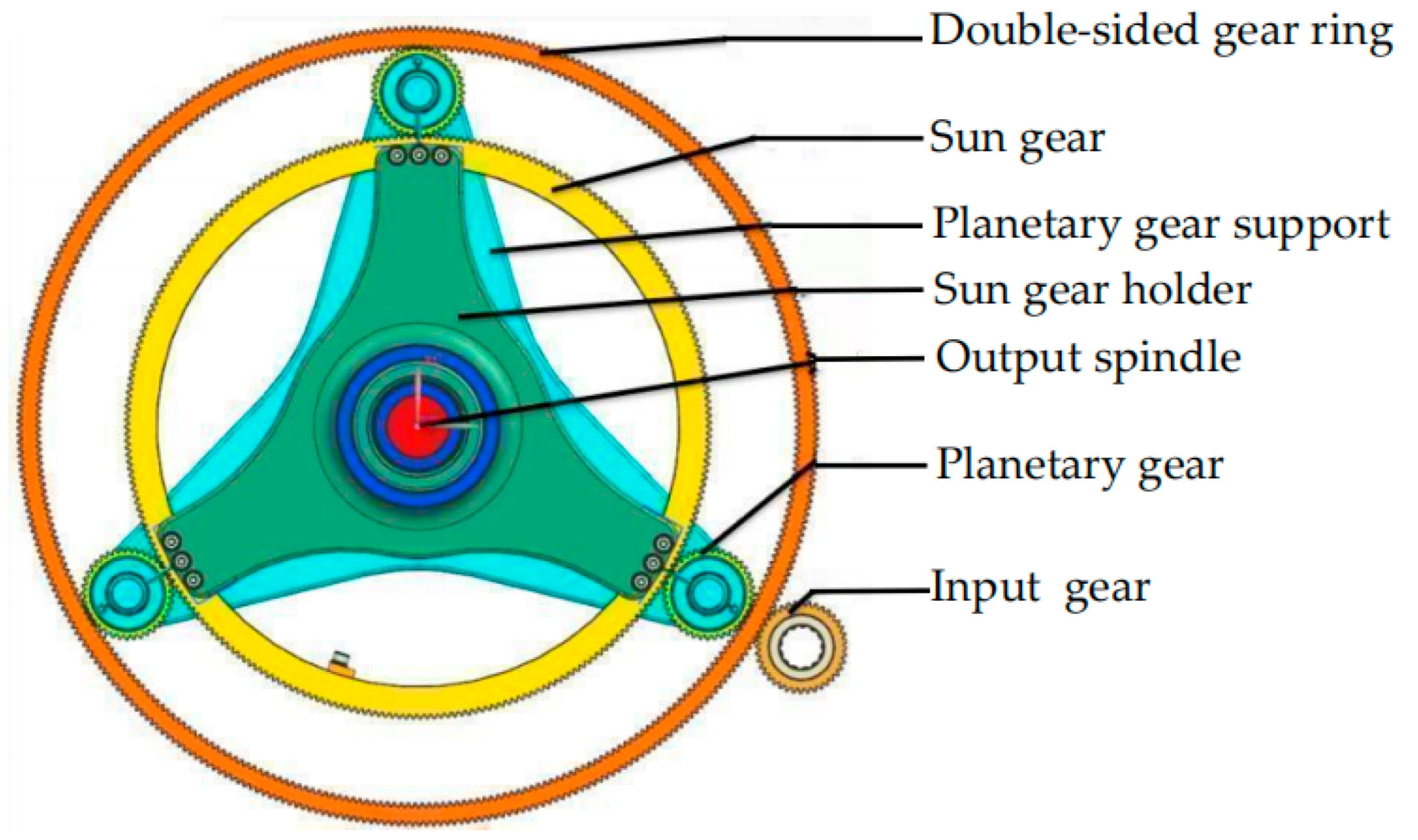
This design adopts a planetary gear transmission system as the core actuator of the energy storage winch. External torque is transmitted to the input gear via the input shaft, which in turn transfers the torque to the outer ring of the double-sided gear ring. The inner ring of the double-sided gear ring engages with the planetary gears; under the constraint of the secondary spring force, the planetary gears rotate around only their own axes without undergoing revolution. Torque is then transmitted from the planetary gears to the sun gear, forming a closed-loop transmission system.
Within this closed-loop system, the planetary gears rotate synchronously with the inner ring of the double-sided gear ring, continuously delivering torque to the sun gear. The coil spring, serving as the core energy storage component, achieves rotational energy storage through this transmission mechanism. The flat spiral spring employed in this study is made of 65 Mn steel, and its detailed parameters are presented in Table 1.
The sun gear bracket is coupled with a one-way clutch to achieve unidirectional locking, ensuring stable torque storage within the planetary-sun gear assembly. When the sun gear reaches its full load capacity, the accumulated torque of the mechanism overcomes the resistance exerted by the secondary spring. As the primary mechanism compresses to its limit position, the sun gear transitions from a driving gear to a driven gear and stops rotating. Simultaneously, the planet carrier starts to rotate, resulting in the planetary gears performing both rotation around their own axes and revolution around the sun gear. Torque from the double-sided gear ring is then transmitted through the planet carrier to the secondary mechanism. The main structure of the single-stage mechanism is depicted in Figure 1.

2.2. Infinite Nested Pattern Design

In multi-unit winch energy storage systems, the synergistic coupling of multiple energy storage modules serves as a sophisticated and pivotal operating mechanism. This procedure covers energy accumulation, conversion and transmission, and relies on precise coordination and efficient collaboration between mechanical components. Accordingly, this section elaborates on the operating principles, functional performance, and energy storage and dissipation characteristics of the multi-group energy storage devices, with in-depth analysis and discussion of key mechanical behaviors.
The cooperative operation of interconnected energy storage devices is divided into two distinct stages: the energy charging phase and the energy discharging phase. These two phases operate alternately during system operation to accommodate variable energy requirements under diverse working conditions.
(1)
Energy Charging Phase
External torque is transmitted via the input shaft to the input gear, which drives the outer ring of the double-sided gear ring. The inner ring of the gear ring further actuates the planetary gears, which perform pure rotation only under the restraining force of the secondary springs. Torque is subsequently delivered to the sun gear for energy accumulation, while the one-way clutch effectively prevents reverse energy reflux. Once the sun gear reaches its maximum energy storage capacity, the superimposed mechanical torque overcomes the resistance of the secondary springs and drives the planet carrier to revolve. Torque is thereby transmitted stage by stage to the subsequent energy storage unit, enabling continuous multi-stage energy charging.
(2)
Energy Discharging Phase
When the system demands power output, each energy storage module discharges elastic potential energy in reverse sequence. Long-distance cable retraction requires high torque; therefore, the final-stage energy storage mechanism is activated first. By contrast, short-distance cable recovery consumes lower torque, allowing the preceding modules to discharge energy in sequence. This matching working mode adapts well to the structural features of the proposed multi-stage nested inverted configuration. The stored elastic potential energy is converted into driving torque, which passes through the main shaft, output wheel, clutch and output gear, and ultimately acts on the winch main shaft to assist the motor in cable retraction. Such auxiliary driving capacity substantially mitigates the motor operating load.
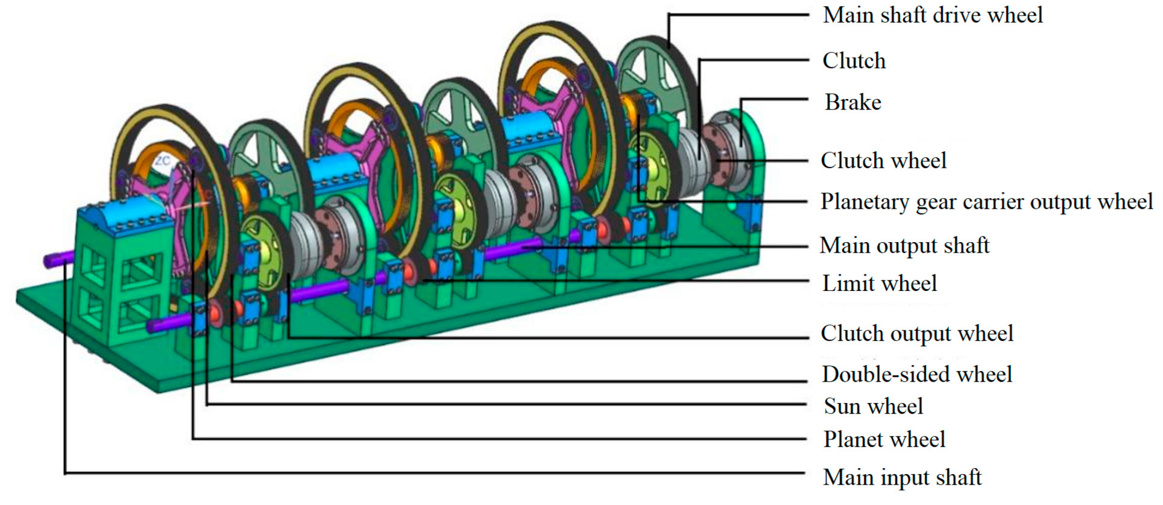
In this work, a three-stage nested structural scheme is adopted for prototype fabrication and experimental testing. The developed energy storage winch system consists of two core subsystems: the energy storage unit and the cable management unit. The key mechanical components of the energy storage unit include the external input shaft, input gear, double-sided gear ring, planetary gears, planet carrier, sun gear, sun gear bracket, and main output shaft. Benefiting from the three-stage nested layout, the energy storage unit achieves a compact structure and high integration density. The overall structural layout is presented in Figure 2.
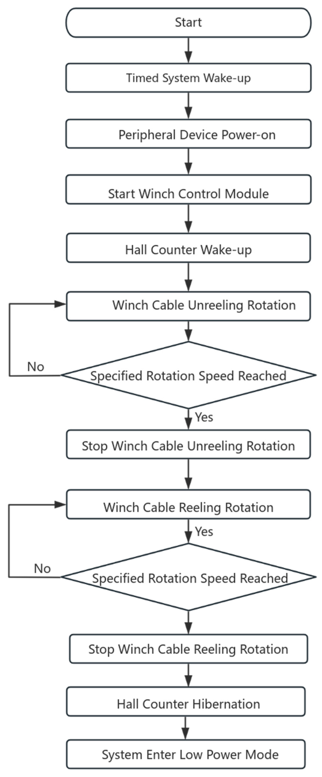
The main body of the cable retraction unit is based on a self-developed semi-submersible lifting quasi-real-time communication mooring mechanism. In this study, Hall effect speed sensors are integrated into the rollers to provide trigger thresholds and closed-loop feedback signals for energy storage and release processes. Meanwhile, a dedicated cable retraction and deployment timing control circuit was developed, with the STM32F103RCT6 microcontroller serving as the main control chip to realize integrated control of motor drive, speed detection, energy storage strategy execution, and fault protection functions. The software workflow of the control circuit is depicted in Figure 3.

3. Land Simulation Experiments

To verify the reliability of elastic potential energy storage and release during the process of the system controlling the motor-driven winch to deploy and retrieve the underwater acquisition device, land-based simulation experiments were performed on the core component (i.e., the energy storage unit) at the Institute of Oceanology, Chinese Academy of Sciences, subsequent to prototype fabrication.

3.1. Experimental Design

The experimental apparatus mainly consists of components, including the computer, energy storage unit, DC motor, simple roller, commutator, DC power supply, data acquisition board, ammeter, pulley and counterweight, as detailed in Table 2.
The energy storage winch model is established based on the energy storage unit, drive motor, cable drum and commutator. Fixed pulleys and counterweights are adopted to simulate the actual underwater observation carrier. The motor is rigidly connected to the cable drum through a coupling. One end of the cable is wound around the drum, while the other end is attached to a counterweight via guide pulleys. Bidirectional rotation of the motor drives the vertical movement of the counterweight, which effectively reproduces the working cycle of marine profile observation winches.

3.2. Experimental Procedures

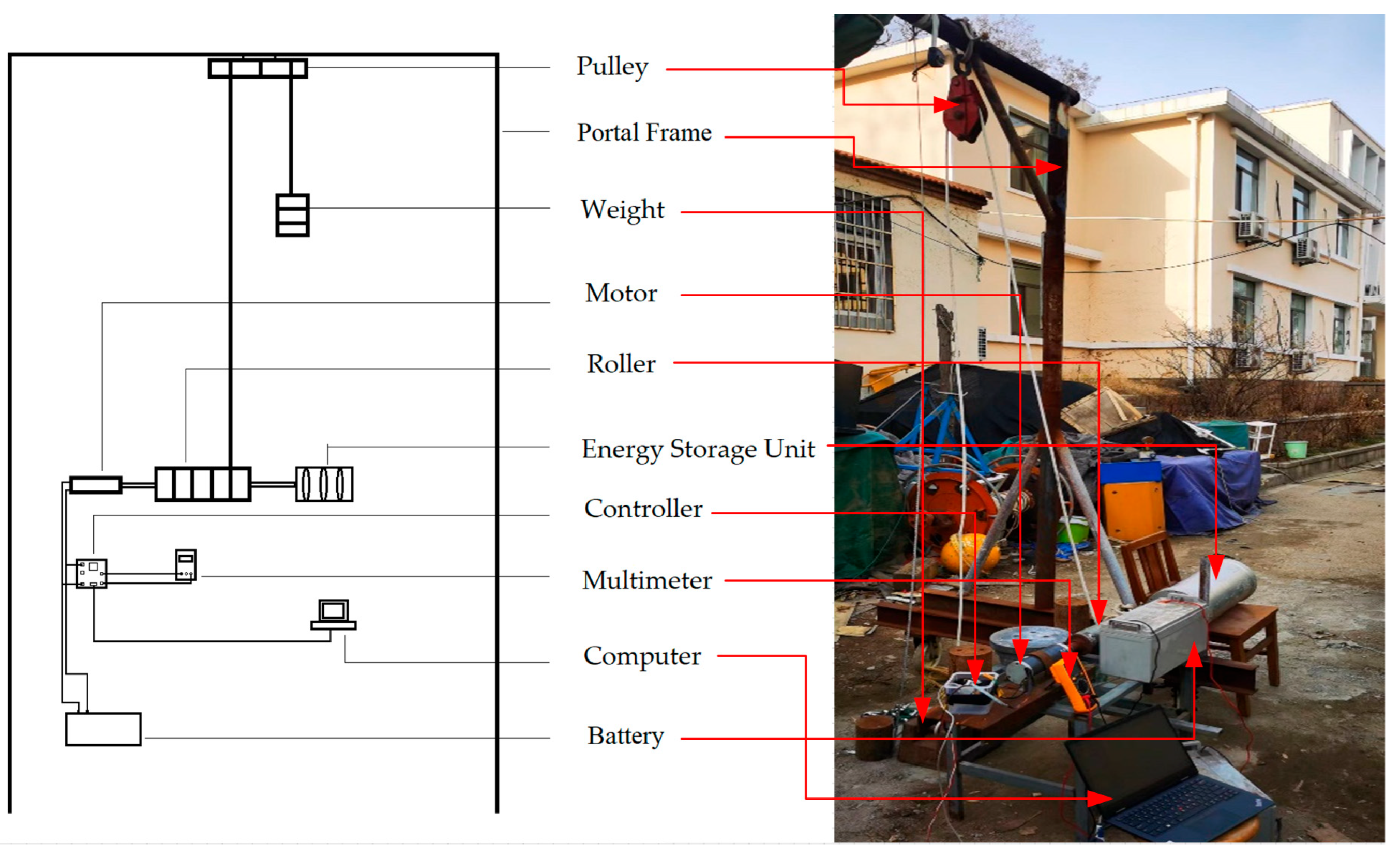
A simple portal frame was fabricated, with a fixed pulley mounted at its apex. A 10 m Kevlar cable was routed through the pulley; one end was fastened to the motor drum, while a standard counterweight was suspended from the other end. A scale was attached to the frame to measure the displacement of the weight. The brushless DC motor was driven via an in-house developed control circuit, and the operating current of the motor was synchronously acquired and recorded throughout the test. The on-shore experimental setup is shown in Figure 4.

3.3. Experimental Results and Analysis

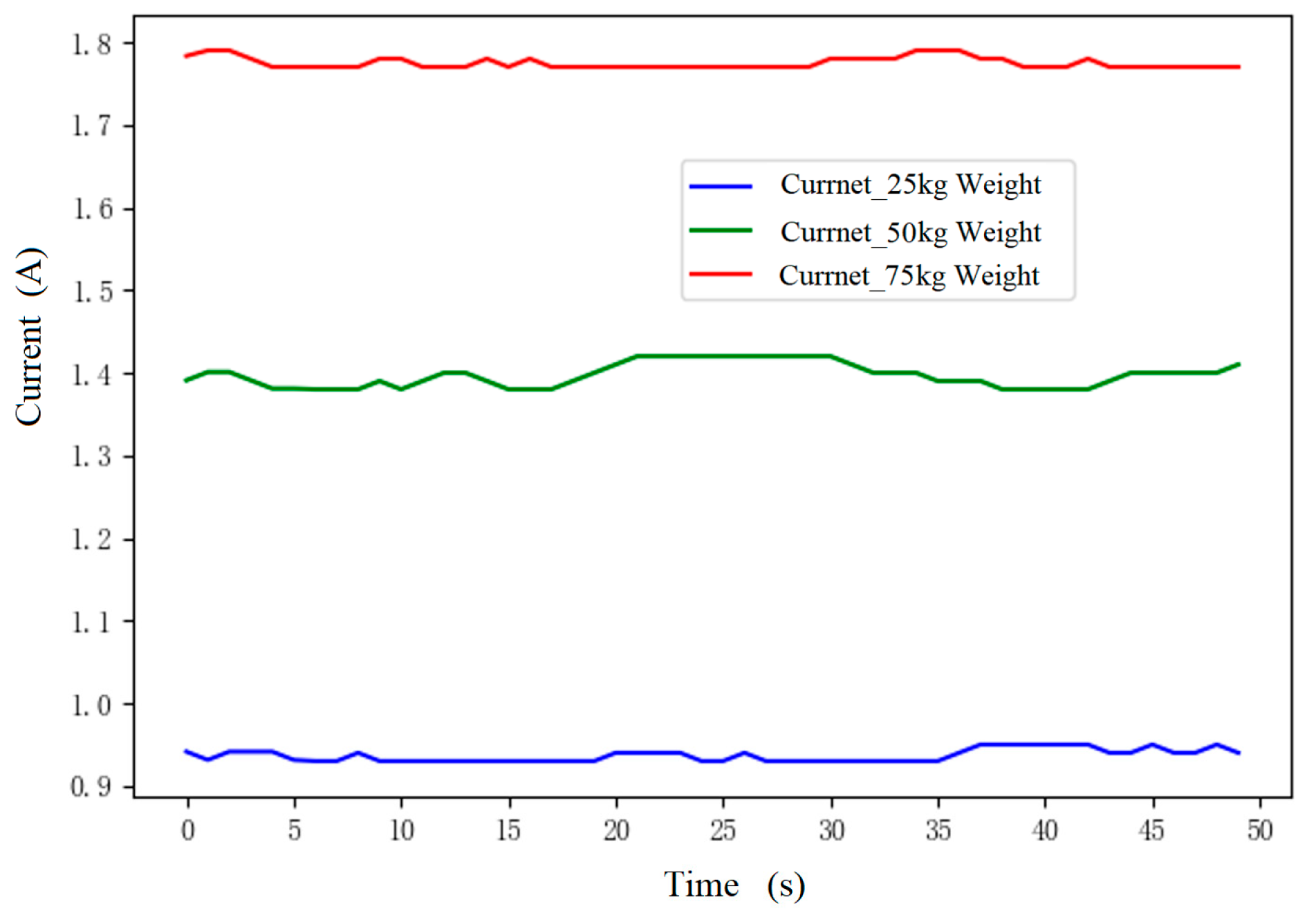
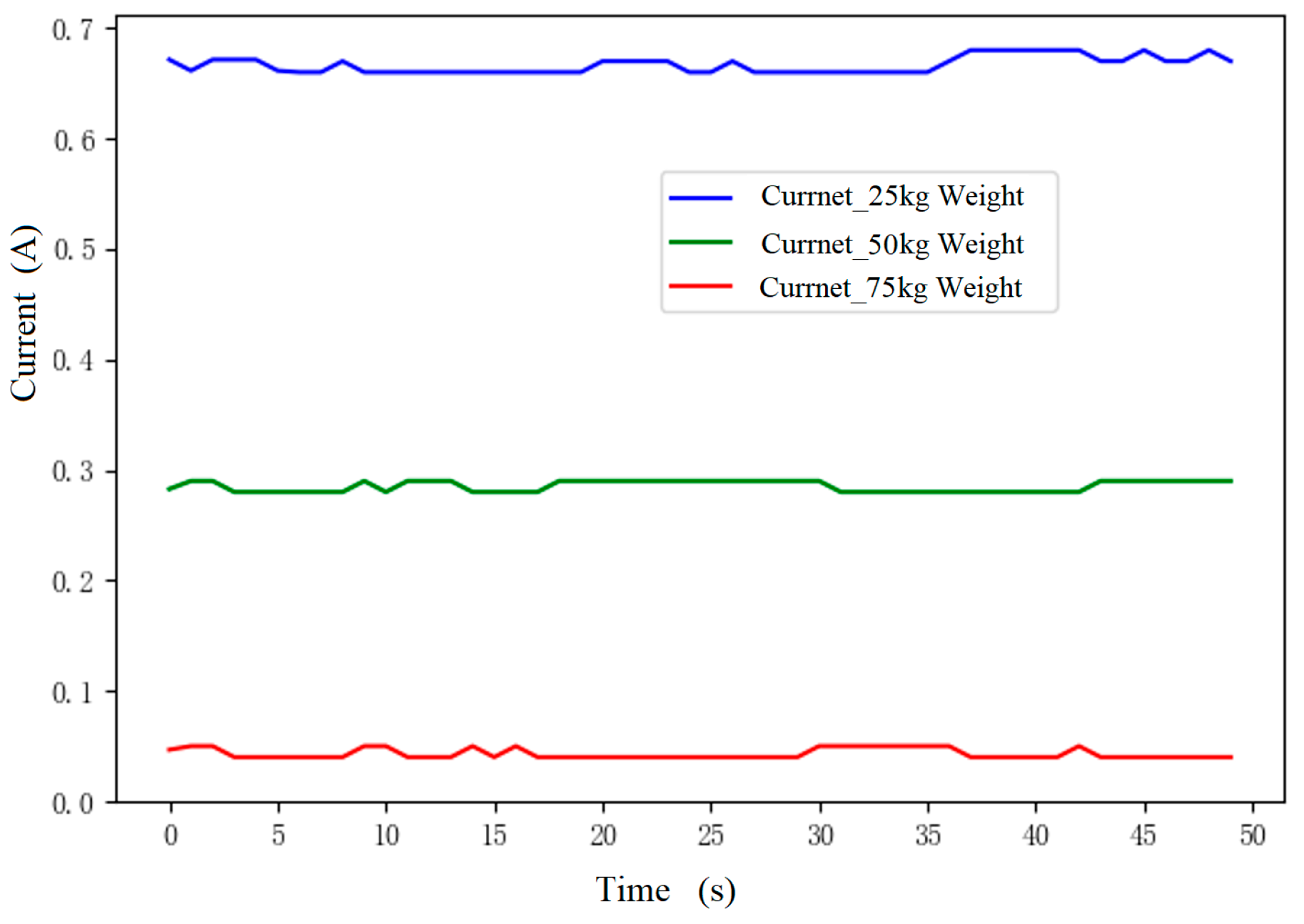
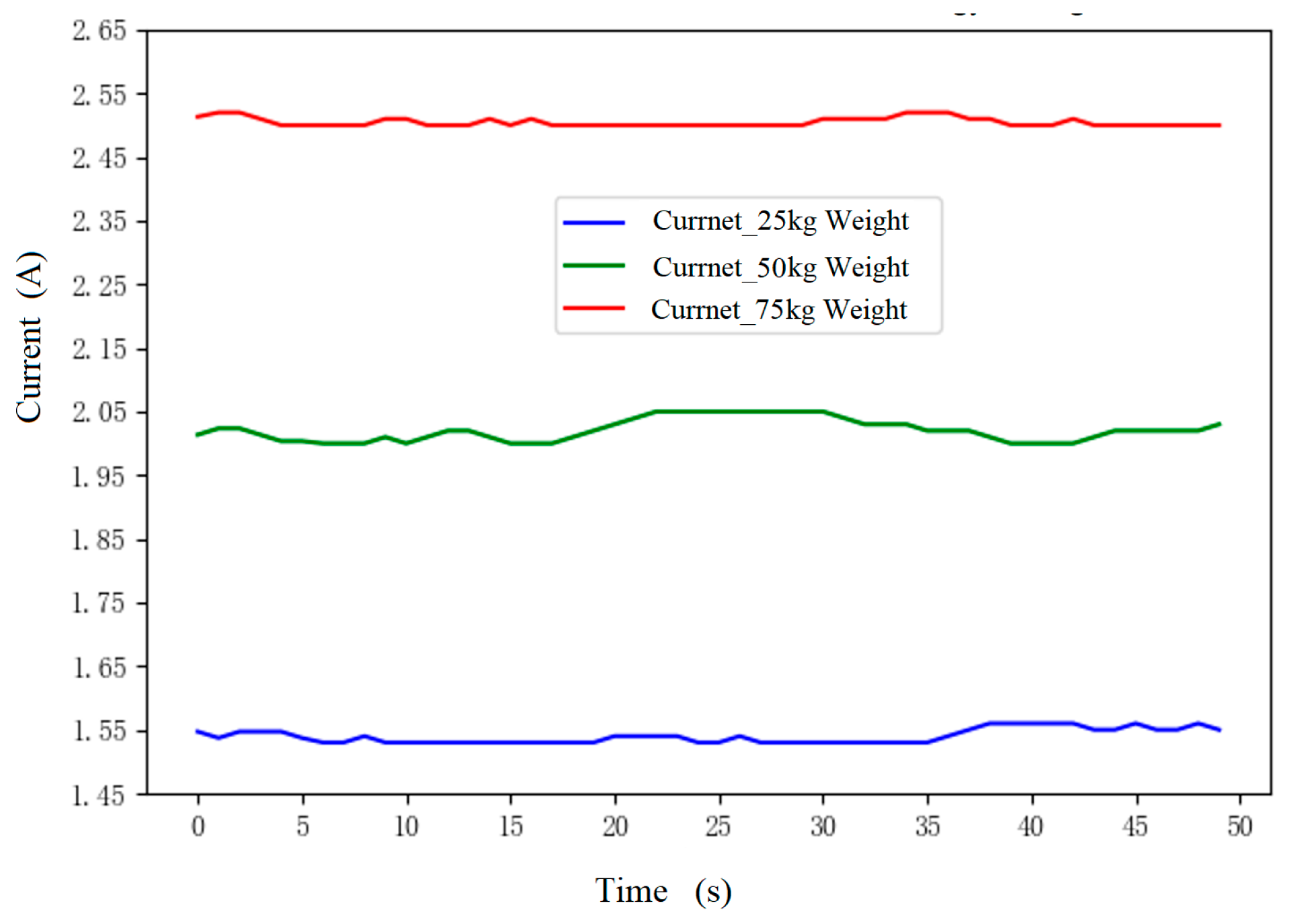
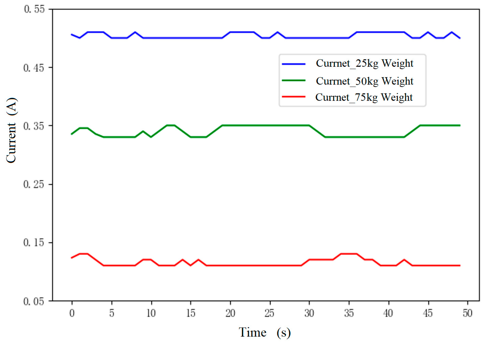
Three groups of lifting and lowering tests were carried out under load conditions of 25 kg, 50 kg, and 75 kg. The motor operating current before and after integration of the energy storage unit was comparatively analyzed. The relevant results are summarized in Table 3 and Table 4.
Table 3 and Table 4, together with the current variation curves in Figure 5, Figure 6, Figure 7 and Figure 8, clearly show that under identical load and lifting stroke conditions, connecting the energy storage unit generally reduces motor current and suppresses current fluctuations. This trend does not apply only to the descending working stages with 50 kg and 75 kg loads. This confirms that the energy storage mechanism can effectively assist the motor in performing work and enhance system energy efficiency. According to the experimental results, during the cable descending process, the motor current with energy storage is higher than that without energy storage, which appears to contradict the anticipated energy-saving effect. This is because the spiral spring is in a compressed state at this stage, and the stored elastic potential energy hinders the weight’s descent under gravity. Once all the elastic potential energy is released, the motor current decreases accordingly and aligns with that observed in the process without energy storage. However, the increase in current during the descending phase is significantly smaller than the decrease in current during the ascending phase. Therefore, when the motor speed remains constant, the total power consumption of the motor with energy storage for the complete ascending and descending process is lower than that of the motor without energy storage.
The experimental results are summarized as follows:
(1)
Cable retraction stage: The energy storage unit releases stored elastic potential energy, which markedly reduces the motor operating current and delivers a prominent energy-saving effect.
(2)
Cable lowering stage: The lowering process is primarily governed by the gravitational force of the counterweight. The energy storage unit mainly completes potential energy accumulation during this phase, thereby exerting only a minor influence on motor current.
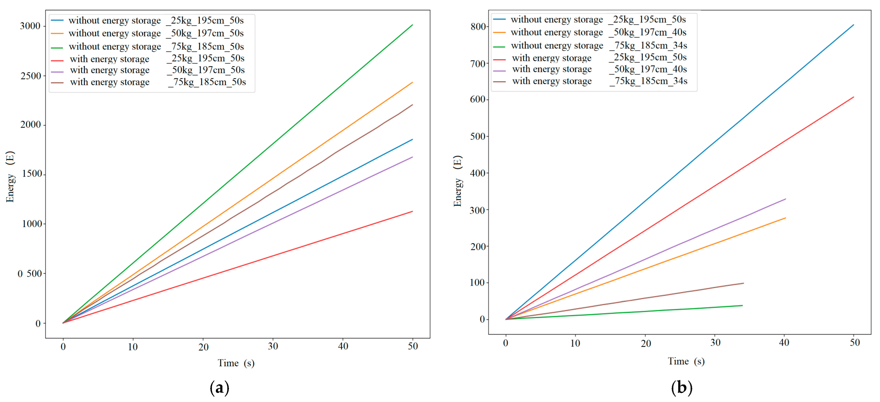
Figure 9 presents the temporal evolution of motor current and energy output during counterweight lifting, with and without the engagement of the energy storage unit. It can be observed that the integration of the energy storage unit substantially narrows the motor current range for both weight ascent and descent. This finding demonstrates that the energy storage unit assists the motor in providing the required driving force more efficiently, enabling the system to accomplish identical mechanical work at a lower current consumption.
Through lifting and lowering tests with different counterweights, real-time motor current data were recorded and analyzed, and the corresponding characteristic curves were plotted. The results indicate that the integration of the energy storage unit reduces energy consumption during both the lifting and lowering processes. This confirms that the energy storage mechanism can effectively assist motor operation and enhance the overall energy efficiency of the system.

4. Real Sea Condition Tests

After the land test of the energy storage unit, the system as a whole was tested in real sea conditions at the West Coast Research Dock campus of the Institute of Oceanology, Chinese Academy of Sciences.

4.1. Objectives of the Experiment

To verify the reliability of elastic potential energy storage and release during the system-controlled operation of the motor-driven winch for deploying and retrieving underwater acquisition devices, and to test the energy-saving performance of the energy storage winch during its operation. Additionally, this study aims to verify the performance of the energy-saving winch under real marine conditions, calculate the energy-saving data during the winch’s operation, and evaluate its energy-saving effectiveness. A “temperature–salinity–depth” sensor is mounted at the winch end to enable marine profile measurement driven by the winch. The temperature, salinity, and depth data of the measured sea area were recorded, and the performance of the energy-saving winch was evaluated to provide experimental data for its subsequent optimization and improvement.

4.2. Experimental Design

The experimental devices are primarily composed of a computer, energy storage winch, DC power supply, data acquisition board, ammeter, pulley system, and sensors for temperature, salinity, and depth, along with a counterweight lead fish. The experiment was conducted at the West Coast Research Dock of the Institute of Oceanology, Chinese Academy of Sciences. Details of the experimental equipment are presented in Table 5.

4.3. Marine Experiment Process

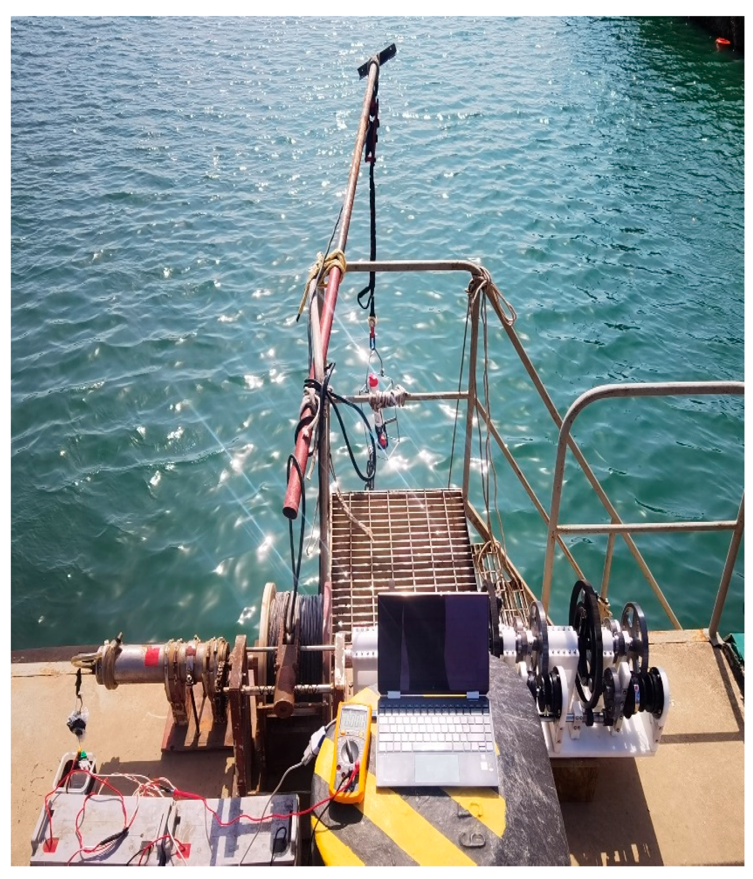
A simple support frame was installed alongside the quay fence. A fixed pulley was mounted at the front end of the frame and fastened to the quay railing. The energy storage winch system consisted of the custom-developed energy storage unit and an in-house-designed marine observation winch. An RBR CTD instrument was adopted to measure nearshore seawater environmental parameters. One end of the cable was wound onto the motor drum, while the other end was connected to the CTD sensor together with a counterweight. The CTD operated in self-recording mode, and the measured depth data were used to calculate the profile measurement range. The energy storage winch was controlled by a computer through a dedicated custom control circuit, enabling real-time collection of motor current data during operation. The overall experimental configuration is presented in Figure 10.

4.4. Results and Analyses

The winch system completed two sets of experiments: one without energy storage unit intervention and the other with energy storage unit intervention. The experimental process is recorded as shown in Table 6 and Table 7 below:
During the cable deployment process of the energy storage winch, the measurement platform is lowered, and the winch rotates forward to pay out the cable. Meanwhile, the drum is subjected to both the gravitational force of the carrier and the traction torque from the coil spring of the energy storage unit. Overall, the gravitational force acting on the measurement platform is greater than the traction force of the coil spring. In this process, the mechanical energy of the motor is converted into the kinetic energy of the measurement platform, the elastic potential energy stored in the coil spring, and a portion of mechanical energy loss.
During the cable retrieval process of the energy storage winch, the measurement platform is recovered. The winch rotates in the reverse direction to retrieve the cable, while the drum is simultaneously subjected to the gravitational force of the carrier and the restoring force of the coil spring in the energy storage unit. Overall, the gravitational force of the measurement platform is greater than the restoring force of the coil spring. In this process, the mechanical energy of the motor and the elastic potential energy stored in the coil spring are converted into the gravitational potential energy of the underwater measurement platform, as well as a portion of mechanical energy loss.
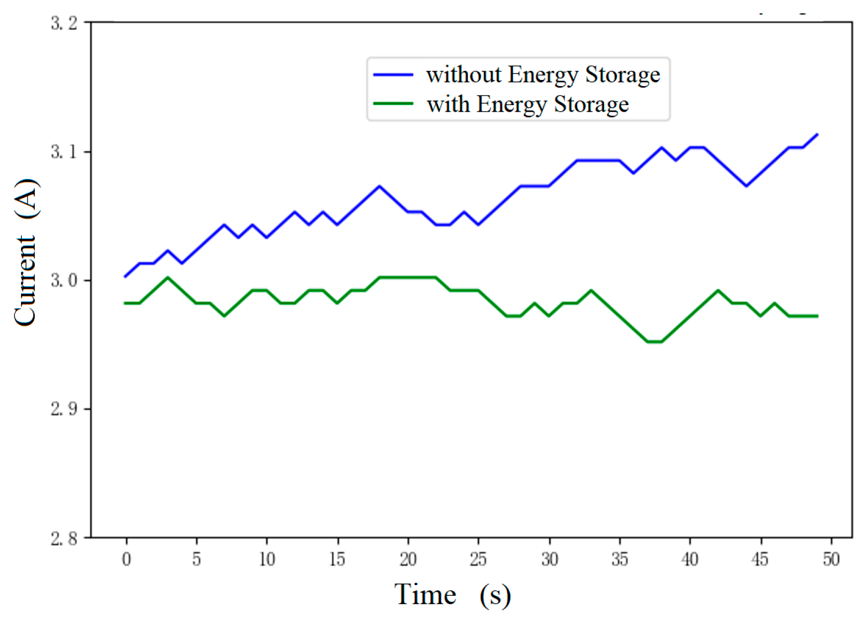
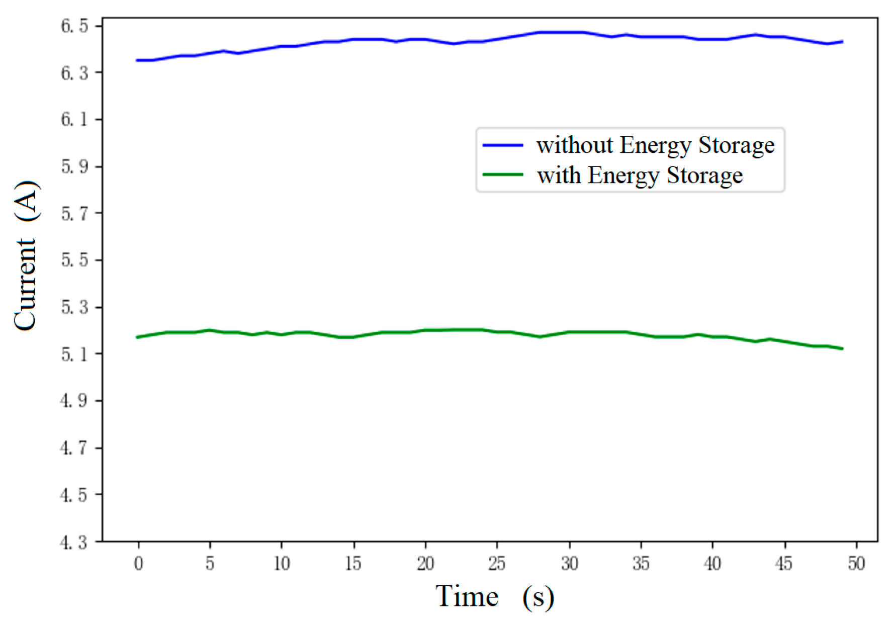
According to the experimental records, the variations in the winch’s operating current during cable deployment and retrieval are plotted in Figure 11 and Figure 12.
Figure 11 illustrates the variation in operating current over time during two cable deployment operations, one with and one without the intervention of the energy storage unit. The blue curve represents the operating current during cable deployment and the descent of the measurement platform to the seabed in the absence of the energy storage unit, with the current fluctuating between approximately 3 A and 3.2 A. The green curve depicts the current variation during the same process with the energy storage unit activated, where the current ranges from about 2.9 A to 3 A. Throughout this process, the elastic potential energy of the energy storage unit is primarily derived from the gravitational potential energy of the measurement platform, exerting a minimal impact on the winch’s operating current.
Figure 12 illustrates the variation in the winch’s operating current over time during two cable retrieval processes: one without and one with the intervention of the energy storage unit. The blue curve shows the operating current variation when the winch tightens the cable and lifts the measurement platform to the sea surface without the energy storage unit, during which the current ranges from 6.3 A to 6.5 A. The green curve represents the operating current variation during the same cable tightening and platform lifting process with the energy storage unit engaged, with the current ranging between 5.1 A and 5.3 A. During this process, the energy storage unit releases elastic potential energy, which effectively reduces the motor load. In addition to the mechanical energy provided by the winch, the stored elastic potential energy contributes to the gravitational potential energy required for lifting the measurement platform, thereby exerting a significant effect on the winch’s operating current.
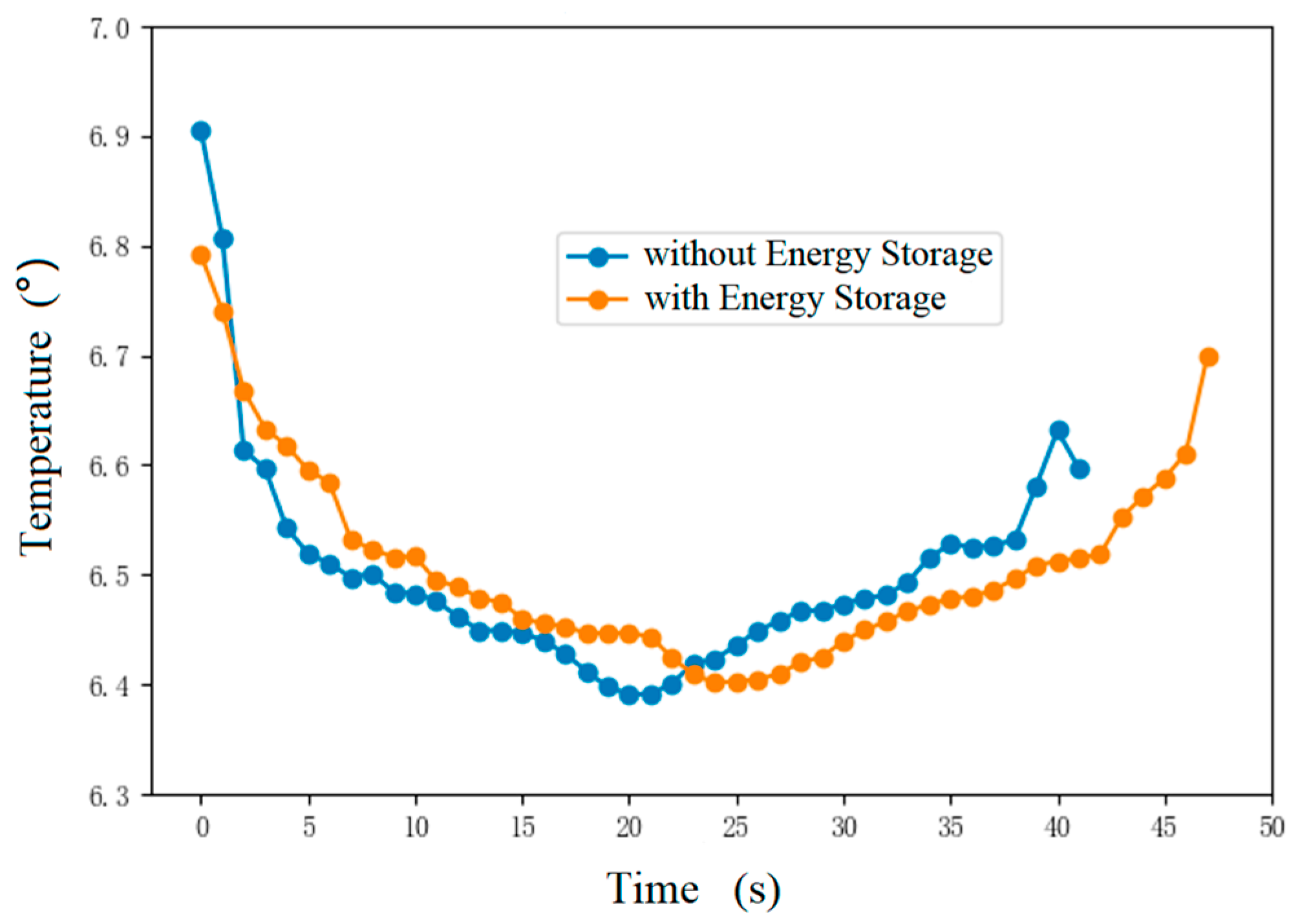
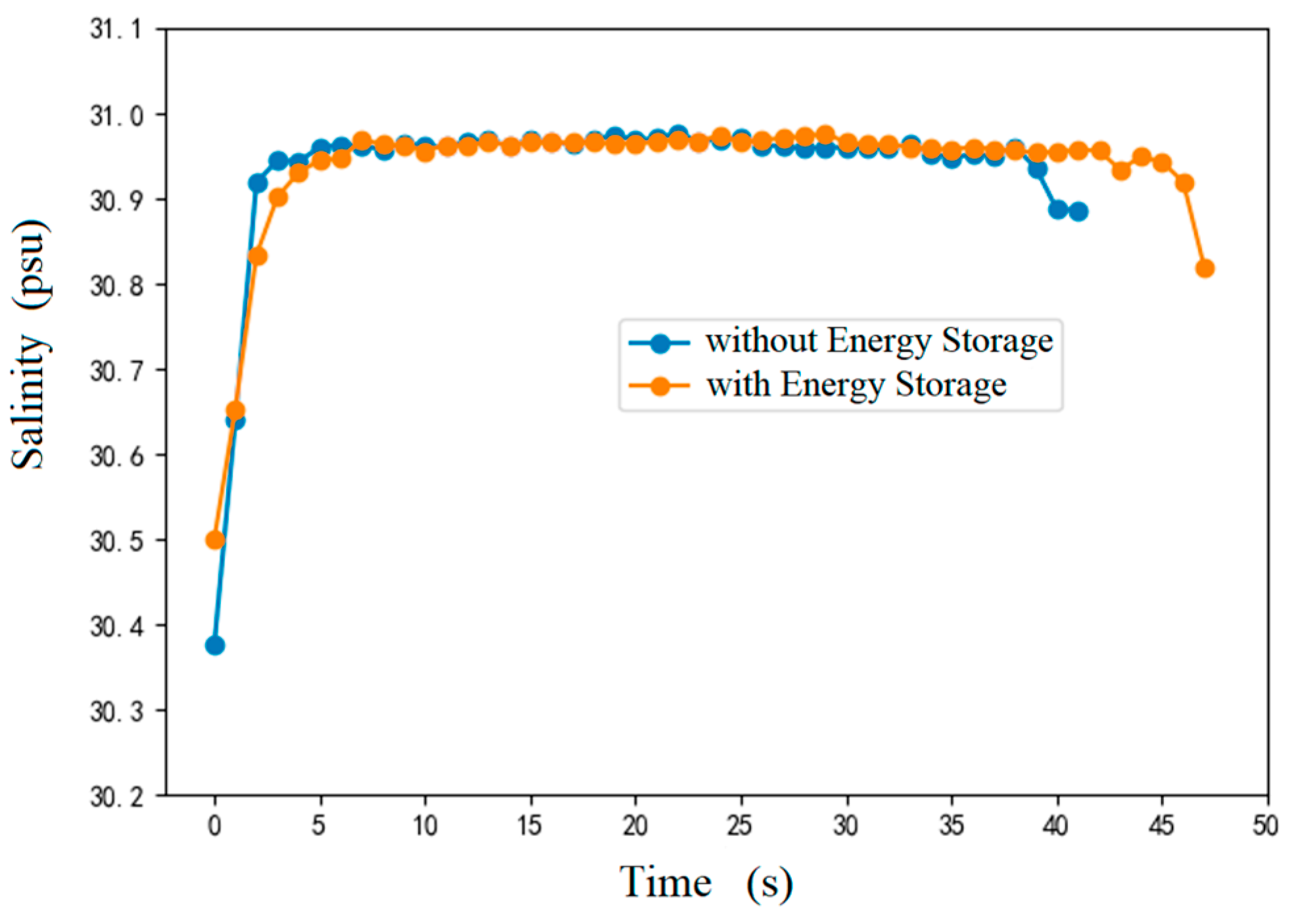
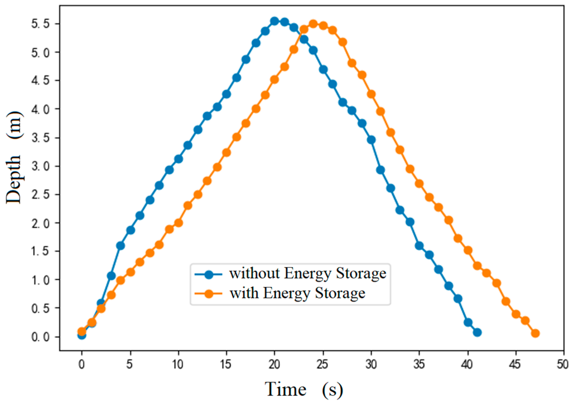
During the experiment, the CTD sensor mounted on the measurement platform collected real-time data on seawater temperature, salinity, and depth. For the sensor-measured parameters obtained during the experiment, time-series curves of seawater temperature, salinity, and depth at the platform were plotted for both scenarios (with and without the energy storage unit), as shown in Figure 13, Figure 14 and Figure 15.
It can be seen from Figure 13, Figure 14 and Figure 15 that the temperature and salinity data of the same water layer obtained by the winch both before and after the intervention of the energy storage unit are essentially consistent. This indicates that the energy storage unit has no impact on the data of ocean element profile observations, and the energy storage winch does not affect the quality of ocean profile measurements.
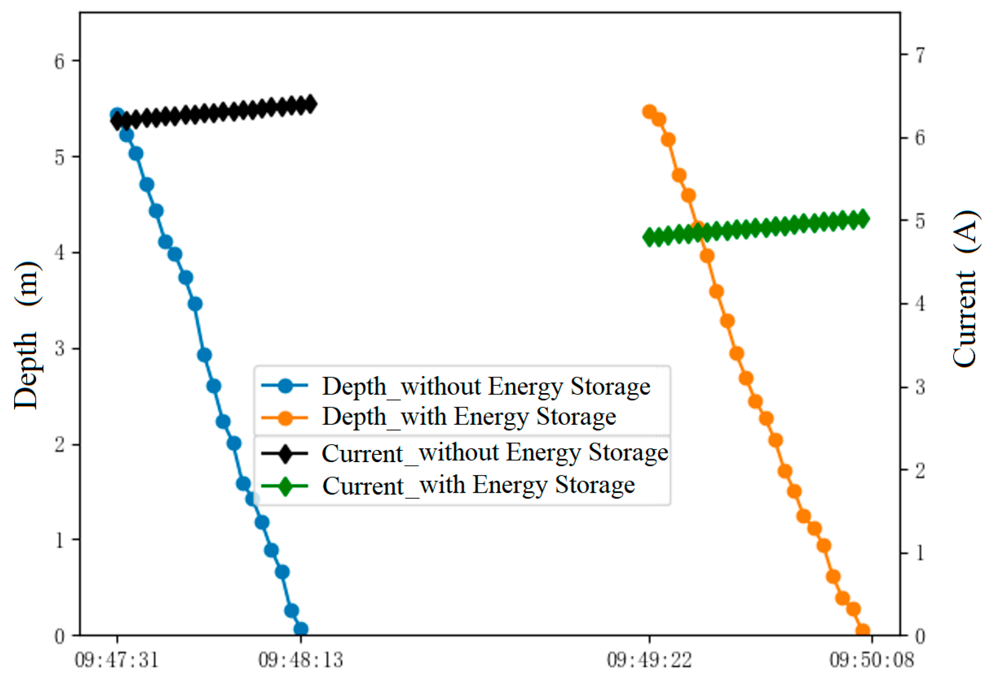
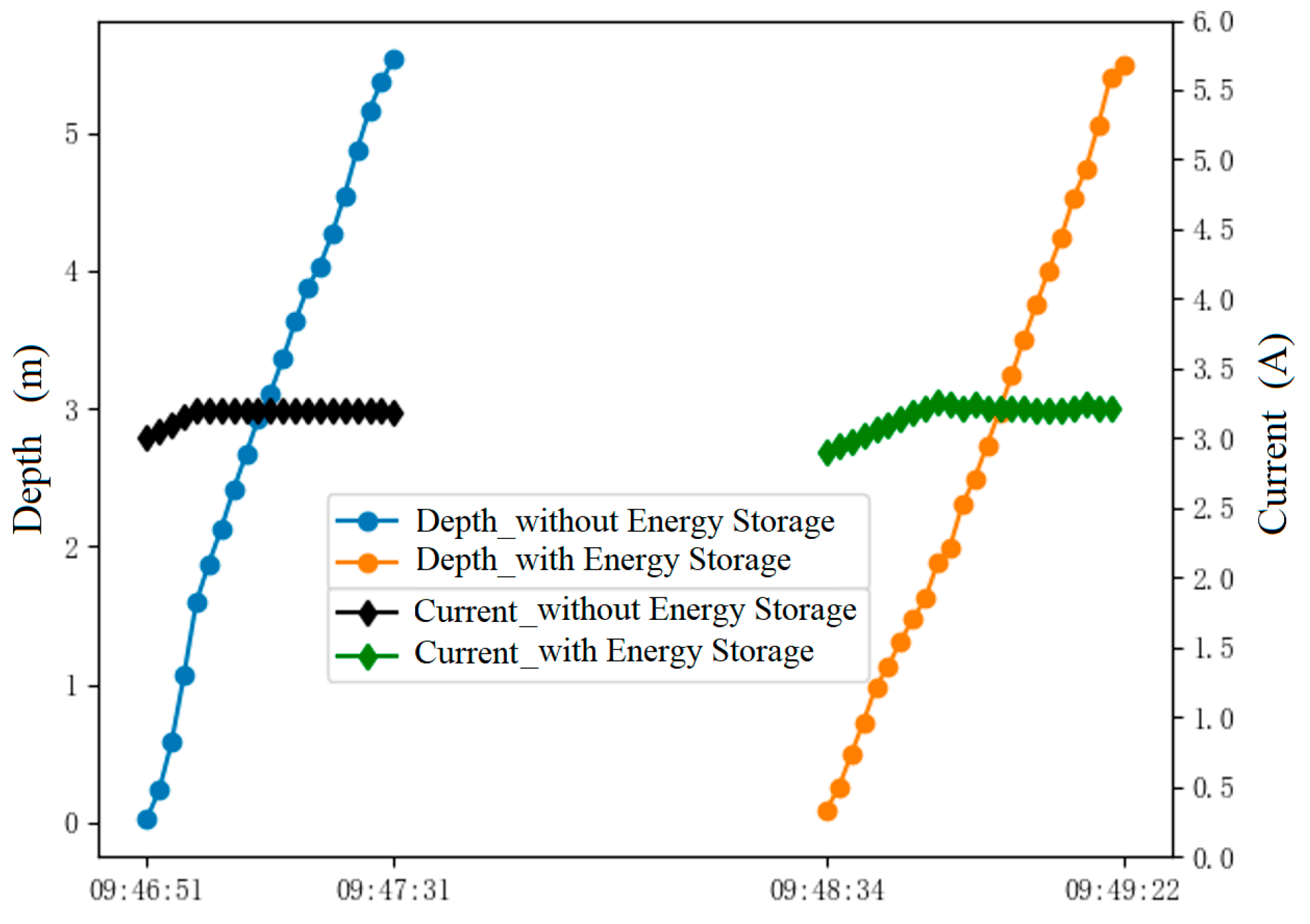
By comparing the winch operating current before and after the intervention of the energy storage unit, comprehensive comparison diagrams of profile depth and winch current (both before and after the completion of profile observation at the same depth) are presented in Figure 16 and Figure 17.
As illustrated in Figure 17, during the process of lowering the winch cable and the measurement platform, the energy storage unit exerts a minimal energy-saving effect on the winch. In contrast, during the cable retraction and lifting of the measurement platform, the energy storage unit achieves a significant energy-saving effect on the winch.

5. Conclusions

This paper presents a novel energy storage winch designed specifically for unmanned marine observation platforms. The winch incorporates a planetary gear-based multi-stage nested mechanism combined with a planar coil spring energy storage structure. This configuration enables the conversion of gravitational potential energy into elastic potential energy during the cable lowering process, and subsequently releases the stored elastic potential energy to assist the motor during the cable retraction process. This design effectively reduces the overall energy consumption of the system. Through structural design, mechanical analysis, prototype fabrication, land-based simulation tests, and nearshore sea trials, the key conclusions are drawn as follows:
(1)
The multi-stage planetary gear-nested structure enables stepwise torque capture, continuous energy storage, and controllable energy release, which can flexibly adapt to the profile observation requirements under varying water depths and load conditions.
(2)
High energy storage density and stable output performance are achieved by selecting 65 Mn steel for the coil springs and adopting lining fixation. Experimental results confirm that the 65 Mn steel coil springs meet the design requirements for strength and toughness, with excellent fatigue resistance under repeated compression and rebound cycles, making it an optimal material choice for the energy storage unit.
(3)
Both land-based simulation tests and real-sea trials indicate that the energy storage winch achieves significant energy-saving effects during the cable retraction phase. Specifically, the motor operating current is substantially reduced, while the accuracy of marine environmental observation data remains unaffected.
(4)
The proposed energy storage winch is well-suited for long-term marine observation equipment, such as unmanned mooring buoys and small-scale scientific research platforms, and demonstrates considerable engineering application potential.

Author Contributions

Conceptualization, J.J. and F.Y.; methodology, J.J.; software, Q.L.; validation, Y.C.; formal analysis, J.J.; investigation, J.J.; resources, J.J.; data curation, Q.L.; writing—original draft preparation, J.J.; writing—review and editing, F.Y.; visualization, Z.N.; supervision, Z.N.; project administration, J.J.; funding acquisition, J.J. All authors have read and agreed to the published version of the manuscript.

Funding

This research was funded by the National Key Research and Development Program of China, grant number 2023YFD2401104.

Data Availability Statement

The data that support the findings of this study are available from the corresponding author upon reasonable request.

Conflicts of Interest

The authors have no conflicts to disclose.

References

  1. Lecours, V.; Disney, M.; He, K.; Pettorelli, N.; Rowcliffe, J.M.; Sankey, T.; Scales, K. Remote sensing and the UN Ocean Decade: High expectations, big opportunities. Remote Sens. Ecol. Conserv. 2022, 8, 267–271. [Google Scholar] [CrossRef]
  2. Carli, E.; Tranchant, Y.-T.; Siegelman, L.; Le Guillou, F.; Morrow, R.; Ballarotta, M.; Vergara, O. Southern ocean 3D eddy diagnostics derived from SWOT. J. Geophys. Res. Oceans 2025, 130, e2024JC022307. [Google Scholar] [CrossRef]
  3. Lochthofen, N.; Frommhold, L.; Ludszuweit, J.; Soltwedel, T. A Subsea Winched Profiling System (SWIPS) for Long-Term High-Resolution Measurements in Ocean Surface Layers. Mar. Technol. Soc. J. 2021, 55, 165–171. [Google Scholar] [CrossRef]
  4. Ostrovskii, A.G.; Emelianov, M.V.; Kochetov, O.Y.; Kremenetskiy, V.V.; Shvoev, D.A.; Volkov, S.V.; Zatsepin, A.G.; Korovchinsky, N.M.; Olshanskiy, V.M.; Olchev, A.V. Automated tethered profiler for hydrophysical and bio-optical measurements in the Black Sea carbon observational site. J. Mar. Sci. Eng. 2022, 10, 322. [Google Scholar] [CrossRef]
  5. Ye, H.; Li, W.; Lin, S.; Ge, Y.; Han, F.; Sun, Y. Experimental investigation of spooling test on the multilayer oceanographic winch with high-performance synthetic fibre rope. Ocean Eng. 2021, 241, 110037. [Google Scholar] [CrossRef]
  6. Li, J.; Lei, S.; Wang, S.; Zhang, C.; Han, G.; Yuan, Z.; Chen, H.; Sun, Y. Dynamic modeling and controller design of a four-cable assisted positioning system for unmanned surface vehicle recovery. Ships Offshore Struct. 2025, 1–33. [Google Scholar] [CrossRef]
  7. Liu, M.; Bennett, A.; Ruan, F.; Li, X.; Lou, J.; Mi, J.; Zuo, L. A Self-Reactive Ocean Wave Energy Converter with Winch-Based Power Take-Off: Design, Prototype, and Experimental Evaluation. In Proceedings of the ASME 2022 International Design Engineering Technical Conferences and Computers and Information in Engineering Conference. Volume 10: 34th Conference on Mechanical Vibration and Sound (VIB), St. Louis, MO, USA, 14–17 August 2022. [Google Scholar] [CrossRef]
  8. Ueland, E.; Sauder, T.; Skjetne, R. Force Tracking Using Actuated Winches with Position-Controlled Motors for Use in Hydrodynamical Model Testing. IEEE Access 2021, 9, 77938–77953. [Google Scholar] [CrossRef]
  9. Defilippo, M.; Robinette, P.; Sacarny, M.; Benjamin, M. The Remote Explorer IV: An Autonomous Vessel for Oceanographic Research. In OCEANS 2019—Marseille, France; IEEE: New York, NY, USA, 2019; pp. 1–8. [Google Scholar] [CrossRef]
  10. Diercks, A.; Sunkara, V.; Bernard, L.; Levesque, F.; Rioux, M.; Dallain, C. High Resolution Spatiotemporal Time Series of Water Column Structure Data Acquired with Autonomous Operated Profiling CTD Mounted on a Viking Met-Ocean Buoy in Support of Autonomous Vehicle Test Area. In OCEANS 2023-MTS/IEEE U.S. Gulf Coast; IEEE: New York, NY, USA, 2023; pp. 1–5. [Google Scholar] [CrossRef]
  11. Poulsen, E.; Rysgaard, S.; Hansen, K.; Karlsson, N.B. Uncrewed aerial vehicle with onboard winch system for rapid, cost-effective, and safe oceanographic profiling in hazardous and inaccessible areas. HardwareX 2024, 18, e00518. [Google Scholar] [CrossRef] [PubMed]
  12. Xu, W.; Su, T.C. A self-sustaining autonomous system for long-term Arctic monitoring. Appl. Ocean Res. 2025, 154, 104316. [Google Scholar] [CrossRef]
  13. Yu, Y.; Yang, Q.; Ji, F.; Zhou, W. Research advances in energy management and harvesting technologies for autonomous profiling floats. Front. Mar. Sci. 2025, 12, 1598701. [Google Scholar] [CrossRef]
  14. Xiao, T.; Huang, J.; Ge, Y. Simulation and control of heave compensation winch for ultra-depth floating drilling. In Proceedings of the 2017 IEEE International Conference on Cybernetics and Intelligent Systems (CIS) and IEEE Conference on Robotics, Automation and Mechatronics (RAM), Ningbo, China, 19–21 November 2017. [Google Scholar]
  15. Zhang, Y.; Gong, T.; Cui, Q.; Zhang, L.; Huang, L.; Zhen, D.; Chen, J. Evaluation method for control performance of marine platform heave compensation systems. In Proceedings of the 2023 International Conference on Oil and Gas Field Exploration and Development, Petroleum and Natural Gas Industry, Wuhan, China, 20–22 September 2023; pp. 112–120. [Google Scholar] [CrossRef]
  16. Ren, H.; Wu, S.; Lin, T.; Zhang, Y.; Miao, C.; Li, Z. Energy Saving Characteristics of a Winch System Driven by a Four-Quadrant Hydraulic Pump. Machines 2022, 10, 1126. [Google Scholar] [CrossRef]
  17. Ji, Y.; Song, H.; Xue, Z.; Li, Z.; Tong, M.; Li, H. A Review of the Efficiency Improvement of Hydraulic Turbines in Energy Recovery. Processes 2023, 11, 1815. [Google Scholar] [CrossRef]
  18. Graves, J.; Kuang, Y.; Zhu, M. Pendulum energy harvester with torsion spring mechanical energy storage regulator. Sens. Actuators A Phys. 2022, 339, 113505. [Google Scholar] [CrossRef]
  19. Chen, J.S.; Chen, I.S. Deformation and vibration of a spiral spring. Int. J. Solids Struct. 2015, 64, 166–175. [Google Scholar] [CrossRef]
Figure 1. Main structure diagram of single-level institutions.
Jmse 14 00861 g001
Figure 2. Structural diagram of three-level nested energy storage unit.
Jmse 14 00861 g002
Figure 3. Software flowchart of timing control circuit.
Jmse 14 00861 g003
Figure 4. The land test diagram.
Jmse 14 00861 g004
Figure 5. Diagram of motor current variation when the weight rises without energy storage unit loading.
Jmse 14 00861 g005
Figure 6. Diagram of motor current variation when the weight rises with energy storage unit loading.
Jmse 14 00861 g006
Figure 7. Diagram of motor current variation when the weight decreases without energy storage unit loading.
Jmse 14 00861 g007
Figure 8. Diagram of motor current variation when the weight decreases with energy storage unit loading.
Jmse 14 00861 g008
Figure 9. Time variation curve of motor energy with the intervention of the energy storage unit. (a) Weight-lifting process. (b) Weight-dropping process.
Jmse 14 00861 g009
Figure 10. Energy storage winch off-shore experiment.
Jmse 14 00861 g010
Figure 11. The variation in the working current of the energy storage unit with winch cable laying.
Jmse 14 00861 g011
Figure 12. The variation in the working current of the energy storage unit with winch cable releasing.
Jmse 14 00861 g012
Figure 13. Changes in seawater profile temperature with energy storage units: the orange curve represents the salinity value of the profile with energy storage units, and the blue curve represents the salinity value of the profile without energy storage units.
Jmse 14 00861 g013
Figure 14. Changes in seawater profile salinity with energy storage units: the orange curve represents the salinity value of the profile with energy storage units, and the blue curve represents the salinity value of the profile without energy storage units.
Jmse 14 00861 g014
Figure 15. Changes in seawater profile depth with energy storage units: the orange curve represents the depth value of the profile with energy storage units, and the blue curve represents the depth value of the profile without energy storage units.
Jmse 14 00861 g015
Figure 16. The changes in the winch cable retraction current and the depth of the measurement platform profile: the black curve represents the current variation during cable retraction without energy storage units, the green curve represents the current variation during cable retraction with energy storage units, the blue curve represents the depth value of the profile without energy storage units, and the orange curve represents the depth value of the profile with energy storage units.
Jmse 14 00861 g016
Figure 17. The changes in the winch cable release current and the depth of the measurement platform profile: the black curve represents the current variation during cable release without energy storage units, the green curve represents the current variation during cable release with energy storage units, the blue curve represents the depth value of the profile without energy storage units, and the orange curve represents the depth value of the profile with energy storage units.
Jmse 14 00861 g017
Table 1. List of hardness and strength of spiral spring steel strip 65 Mn.
Hardness HVHardness HRCStrength (σb N/mm2)
374–48540–481275–1600
Table 2. List of on-shore testing equipment.
Devices Used in the TestQuantityParameter Values
Computer1associate
Energy storage unit1Self-developed
DC motor1Z82BLDPN24200-30S (Permanent Magnets)
Simple roller1Self-developed
Commutator1Self-developed
DC power supply212V-100AH battery
Data acquisition board1Self-developed
Ammeter1Victor 890D
Pulley1Lifting 5 tons
Counterweight weights325 kg
Keff pull rope1Length 10 m, diameter 12 mm
Table 3. Record table of experimental data for motor cable collection.
WeightsRising
Height
Ascending
In Time
Motor Current
(Without Energy Storage)
Motor Current
(with Energy Storage)
25 kg195 cm50 s1.53 A~1.56 A0.93 A~0.95 A
50 kg197 cm50 s2 A~2.05 A1.38 A~1.42 A
75 kg185 cm50 s2.5 A~2.52 A1.77 A~1.79 A
Table 4. Record table of experimental data for motor cable retraction.
WeightsDecline
Height
Descent
In Time
Motor Current
(Without Energy Storage)
Motor Current
(with Energy Storage)
25 kg195 cm50 s0.58 A~0.66 A0.5 A~0.51 A
50 kg168 cm40 s0.28 A~0.29 A0.33 A~0.35 A
75 kg185 cm34 s0.04 A~0.05 A0.11 A~0.13 A
Table 5. Equipment list for near-shore real sea state experiment.
Devices Used in the ExperimentQuantityParameter Values
Computer1HP
Energy storage unit1Self-developed
Winch1Self-developed
DC power supply212V-100AH battery
Data acquisition board1Self-developed
Ammeter1Victor 890D
Pulley1Lifting 5 tons
Measuring platform1Self-developed with RBR-CTD
Simple stand1Self-developed
Pincer fish115 kg
Table 6. Record table of experimental data for winch cable collection without energy storage unit.
Experimental ProjectMeasurement PlatformProfile DepthWhen UsedMotor Current (no Energy Storage)
Winch release cable22 kg552 cm40 s3 A to 3.2 A
Winch harvesting22 kg547 cm42 s6.2 A to 6.5 A
Table 7. Record table of experimental data for winch cable collection with energy storage unit.
Experimental ProjectMeasurement PlatformProfile DepthTime UsedMotor Current (with Energy Storage)
Winch release cable22 kg545 cm48 s2.9 A ~ 3 A
Winch harvesting22 kg549 cm46 s4.8 A to 5.2 A
Disclaimer/Publisher’s Note: The statements, opinions and data contained in all publications are solely those of the individual author(s) and contributor(s) and not of MDPI and/or the editor(s). MDPI and/or the editor(s) disclaim responsibility for any injury to people or property resulting from any ideas, methods, instructions or products referred to in the content.