1. Introduction
Multi-robot collaboration and marine robotics constitute key research directions in intelligent autonomous systems. With the rapid advancement of underwater vehicle technologies, multi-ROV cooperative operations are increasingly deployed for complex maritime missions, particularly in sunken ship search-and-rescue scenarios where efficiency, coverage, and robustness are paramount. The integration of autonomous planning and control architectures for coordinated multi-ROV systems has thus emerged as a critical enabler for enhancing the effectiveness of underwater search operations.
Since humanity embarked on the journey of ocean exploration, shipwreck incidents have frequently occurred. Subsequent to shipwrecks, air chambers can be formed in the enclosed spaces of hulls under certain conditions, which can be utilized as critical shelters for distressed personnel to maintain vital signs and await external rescue. In 1939, the USS Squalus submarine of the United States Navy sank to a depth of 74 m, and a stable air chamber was created by the sealed forward compartment, allowing 33 crew members to survive until the arrival of rescue teams. In 2013, following the capsizing of the Nigerian tugboat Jascon 4, crew member Harrison was rescued after surviving for 60 h in a compressed air layer merely 1.2 m high in the toilet adjacent to the engineer’s office.
Nevertheless, the existence of air chambers only secures a valuable time window for rescue operations, while the inherent limitations of traditional search-and-rescue modes have not been fundamentally eliminated. In 1997, in the icy waters of Antarctica, British navigator Blymore survived for 140 h in the air chamber of a capsized sailboat with only a chocolate bar and a small quantity of fresh water, and was eventually detected by a frigate of the Royal Australian Navy.
It has been indicated by relevant studies that the golden rescue window period for shipwreck search and rescue normally does not exceed 72 h. Although air chambers formed after vessel submergence can supply distressed personnel with life-sustaining oxygen, such spaces are not hermetically sealed and stable. Oxygen concentration inside the air chambers is continuously reduced with water seepage in the cabins and respiratory consumption, while carbon dioxide concentration is gradually elevated. In the context where the efficiency of traditional search-and-rescue methods is severely limited, how to determine the location of the sunken ship before oxygen runs out has become a key factor in improving the survival rate of the survivors.
Compared with traditional manual marine search and rescue, underwater robots demonstrate irreplaceable core advantages in operation scope, work efficiency and safety assurance. In terms of operation space, the physiological constraints of human beings are not imposed on underwater robots, which can be deployed to extreme and harsh environments in the deep sea, breaking through the limits of human diving depth and operational conditions. In terms of operation efficiency, long-term continuous operations can be conducted by underwater robots without being restricted by working hours, and the efficiency and quality of shipwreck search and rescue are significantly improved. In terms of operation safety, for high-risk tasks, including underwater pipeline inspection, shipwreck salvage, emergency rescue, and construction in high-risk waters, operations in hazardous environments can be fulfilled by underwater robots instead of personnel, which greatly enhances the safety factor of underwater operations. Therefore, the new generation of underwater robots with autonomy and intelligence as the core will gradually reshape the traditional underwater search-and-rescue operation system, and comprehensively replace the manual underwater operation mode featuring low efficiency and high risks.
In shipwreck search scenarios, extremely stringent requirements are imposed on the motion control of underwater vehicles due to complex seabed topography and turbulent current conditions. This necessitates that trajectory planning algorithms dynamically generate obstacle-avoidance trajectories based on real-time bathymetric data to precisely cover designated search zones in target waters, while tracking control technologies must be relied upon to ensure stable adherence to predefined trajectories under strong disturbances, thereby preventing collisions with obstacles and mission failures caused by tracking deviations. For unknown environments, it is impossible to provide trajectories in advance for tracking. Moreover, since real-time mapping data is mapped along with the movement of underwater vehicles, it is also impossible to conduct trajectory planning first and then carry out tracking control. Therefore, it is necessary to study the real-time trajectory planning and tracking control of underwater vehicles. A Remotely Operated Vehicle (ROV) is categorized as a type of underwater vehicle, which is characterized by advantages such as economy, high efficiency, unlimited operation time, and stable communication capabilities [
1].
At present, there are many methods for trajectory planning for underwater vehicles. While conventional planning methods remain widely utilized in engineering practice, reinforcement learning has emerged as a prominent research direction, attracting growing attention in recent years. Researchers such as Behnaz Hadi have used deep learning and its derivative technologies to plan the trajectories of underwater vehicles [
2,
3]. Tao Liu et al. proposed a navigation method that integrates the principle of reciprocal velocity obstacles and the control of model predictive path integral [
4]. Xinyu Jian et al. proposed an improved hybrid programming strategy using dynamic window approach (DWA) and fast exploration random tree [
5]. Rui Wang et al. proposed a stepwise programming algorithm, integrating time-space Bezier curves and Particle Swarm Optimization (PSO) to achieve multi-BUV cooperative formation and efficient obstacle avoidance re-planning [
6]. Deep reinforcement learning indeed enables stronger autonomy and potential optimization space in complex unknown environments, but its data-driven nature results in high computational cost, difficult safety verification, and heavy reliance on training quality. By contrast, methods like PSO are better suited for scenarios where global optimization in static environments is required, models are precisely known, and offline planning is allowed. DWA designs a reactive local planning and rapid safety assessment framework, making it particularly suitable for dynamic unknown environments. Consequently, in practical terms, DWA is demonstrated to be applicable for multi-ROV trajectory planning.
At present, there are many methods to track and control the underwater vehicle. Researchers such as Hongtao Liang and Zhao Wang used deep learning to track and control underwater robots [
7,
8]. Researchers such as Yuan Chen used sliding mode control (SMC) and its derivative technologies to track and control underwater robots [
9,
10,
11,
12]. Traditional SMC is inherently limited by its dependence on discontinuous switching control laws, which tend to induce actuator wear. The methodology is incapable of predicting trajectories or explicitly satisfying complex constraints, while its robust performance is constrained by conservative parameter design, rendering the system inadequately prepared to handle time-varying disturbances. Researchers such as Haoyu Yang have used model predictive control (MPC) and its derivative technologies to track and control underwater robots [
13,
14,
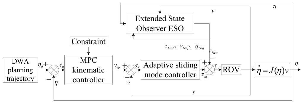
15]. MPC shows superior performance in dealing with complex constraints and generating optimized reference trajectories for ROVs. Nevertheless, its performance is highly dependent on the accuracy of kinematic and dynamic models, and the online optimization process will bring corresponding computational delay, which makes it unsuitable to be directly employed as a high-frequency inner-loop controller. In contrast, adaptive sliding mode control (ASMC) possesses strong robustness against model uncertainties and external disturbances with low computational complexity, which is competent for high-frequency real-time closed-loop control. However, it lacks the ability of global trajectory optimization and explicit constraint management. Given the complementary advantages of the two control methods, the hierarchical structure with outer-loop MPC and inner-loop ASMC has become a common scheme in relevant research. In this paper, this mature and effective control architecture is adopted. By decomposing kinematic optimization and dynamic tracking tasks, the advantages of MPC in constraint handling and trajectory optimization, as well as the merits of ASMC in robustness and real-time performance, can be fully utilized, so as to improve the overall performance of the control system.
Despite significant progress in individual domains, such as reactive local planning via DWA, constrained optimal control via MPC, robust dynamic tracking via ASMC, and disturbance estimation via extended state observer (ESO), existing approaches typically address these challenges in isolation. In the context of multi-ROV collaborative search, a fundamental research gap remains: how to simultaneously ensure efficient, non-redundant coverage among multiple vehicles while maintaining precise trajectory tracking under both actuator saturation and strong hydrodynamic disturbances. Conventional DWA formulations lack inter-vehicle coordination mechanisms and are therefore prone to search overlap and blind zones in deployments involving multiple agents. Standard MPC- and adaptive sliding mode control (ASMC)-cascaded controllers, although effective for constraint handling and robustness with a single vehicle, do not inherently compensate for unknown environmental disturbances unless augmented with active feedforward strategies. Conversely, ESO-based disturbance rejection schemes are seldom integrated into a complete planning and control hierarchy that explicitly accounts for multi-vehicle search coordination and thruster limitations. To bridge this gap, the present work proposes an integrated framework that couples an augmented leader and follower DWA planner with a cascaded kinematic and dynamic tracking controller enhanced by ESO-based feedforward compensation. This unified architecture is specifically designed to reconcile the competing demands of formation coverage, constraint satisfaction, and disturbance rejection in time-critical shipwreck search scenarios. The proposed framework is outlined as follows.
In this paper, an improved DWA is used to construct a multi-ROV collaborative search architecture for trajectory planning. For tracking control, a cascade control structure is formed by combining a kinematic controller and an adaptive dynamic controller. DWA is a local path planning algorithm based on velocity space, which is often employed for dynamic obstacle avoidance and real-time trajectory optimization. To address the issues of repeated detection and coverage blind spots in multi-ROV formation search under the traditional DWA algorithm, this study proposes a hierarchical optimization architecture based on dynamic potential field adjustment. The core idea of this architecture is to achieve the collaborative optimization of formation safety and search efficiency through a distance-sensitive coupling mechanism. Specifically, it deeply integrates formation collaboration constraints into the heading, obstacle avoidance, and speed evaluation framework of the classical DWA. For the tracking control of ROVs, MPC is combined with it to form a dual-loop tracking control system. In this configuration, MPC serves as the kinematic controller in the position outer loop, converting the desired position into a velocity reference signal. ASMC functions as the dynamic controller in the velocity inner loop, tracking the velocity reference and generating actuator torque commands. In ROV tracking control, disturbances encompass various non-ideal factors that affect the motion state or trajectory of the vehicle, arising from complex and diverse sources. To mitigate the impact of unknown disturbances on ROV tracking performance, this paper incorporates an ESO in conjunction with ASMC. The ESO treats uncertainties such as unmodeled dynamics, parameter variations, and external interferences as a lumped total disturbance and provides real-time disturbance estimation for feedforward compensation. The combined controller thereby realizes closed-loop optimization, encompassing disturbance estimation, feedforward compensation, and robust control.
The remainder of this paper is structured as follows: the improved DWA integrated with search distance penalty for multi-ROV cooperative trajectory planning, which is proposed to solve the problems of repeated detection and coverage blind spots in cooperative search, is elaborated in
Section 2; the dual-loop tracking control framework consisting of MPC and ASMC, which is developed to realize high-performance trajectory tracking under strong underwater disturbances and thruster constraints, is presented in
Section 3; simulation experiments and a comprehensive result analysis to verify the effectiveness of the proposed trajectory planning and control methods are provided in
Section 4; and, finally, the whole work is concluded and possible future research directions are discussed in
Section 5.
2. DWA Trajectory Planning
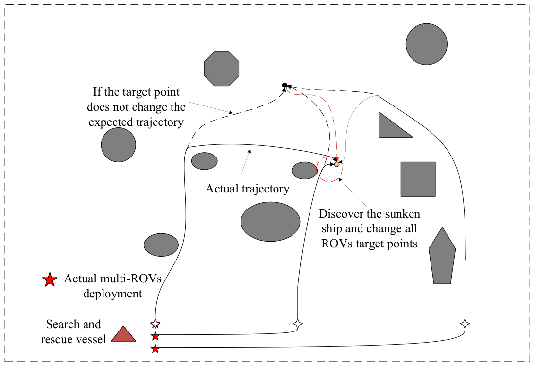
Consider that, if the ship sinks after a signal is sent on the sea surface, the actual sinking position of the ship is often not the position where the signal is sent, but will drift under natural factors such as ocean wind, ocean currents, and tides, and eventually deviate from the signal position. Search-and-rescue personnel can roughly estimate the offset position based on meteorological data and experience, but the actual search requires ROVs. A single ROV cannot cover all the search areas well, so multiple ROVs need to be used for collaborative search. When a certain ROV searches for the wreck, it sends a signal to inform the rest of the ROVs to move closer to its own position, which is convenient for subsequent careful search and recovery. The schematic diagram of multi-ROV collaborative search is shown in
Figure 1.
In
Figure 1, the black target point represents the position of the final signal, and the orange target point represents the actual shipwreck position under the action of ocean current. The gray areas of different shapes represent different obstacles. The black dotted line represents the planned trajectory if the target point is not moved, while the black solid line represents the actual planned trajectory.
Because it is used to verify the multi-ROV trajectory planning and tracking control system proposed in this paper, it is simplified to three ROVs. The trajectory planning and tracking control system for three ROVs can be used to represent that multiple ROVs can use the same trajectory planning and tracking control system for synergy. Here, there are three ROVs: one is the leader ROV, and the other two are the follower ROVs.
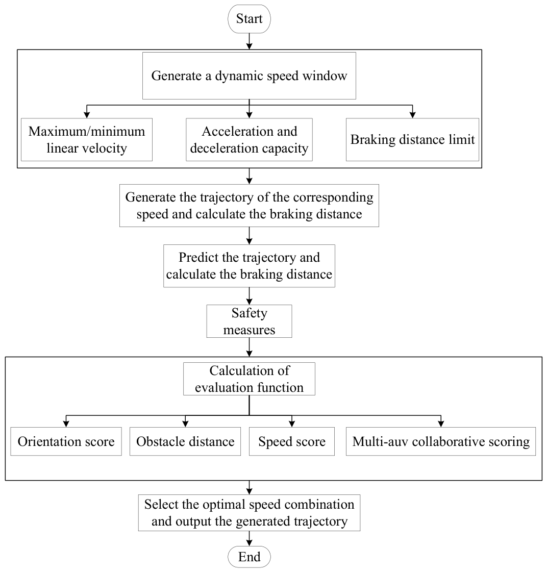
The task of trajectory planning is to generate trajectory points based on real-time mapping data within a limited time, with the capability to realize the planning for target points and the avoidance of obstacles. The improved DWA is adopted for trajectory planning in this paper, and the main block diagram of the improved DWA trajectory planning is presented in
Figure 2. The main module of DWA is the dynamic window. It generates all possible feasible velocity ranges within a short sampling period based on the given maximum velocity, maximum acceleration and maximum angular velocity. Through discretization, it forms combinations containing numerous candidate linear velocities and angular velocities. Then, based on the kinematic model, it predicts the motion trajectory of each velocity combination within a certain period of time in the future. Then, the score is assigned and normalized through the objective function. The higher the score, the more the trajectory meets the requirements. The trajectory
with the highest score is output to the tracking control link as a reference trajectory.
2.1. ROV Kinematic Model
The three-dimensional planar motion of ROVs is studied in this paper, so only four degrees of freedom are considered, namely, surge
, sway
, heave
, and yaw
. The pose and speed of ROV can be expressed as
,
. The kinematic model can be expressed in the following form [
16]:
The Falcon system is employed as the simulation prototype for the ROV, where five thrusters are configured, comprising four horizontal thrusters and one vertical thruster, thereby enabling independent motion in all directions. Given the minimal displacement of the ROV over consecutive time intervals, its motion can be approximated as uniform linear motion, with the kinematic model formulated as follows:
2.2. Speed Sampling
The International Regulations for Preventing Collisions at Sea (COLREGs) applicable to surface vessels do not directly govern underwater ROV operations, whereas the ROV operational guidelines established by the International Marine Contractors Association (IMCA) have become the universal safety framework in the industry [
17,
18].
The core logic inherits key maritime safety principles from COLREGs, including safe speed, safe encounter distance, effective collision avoidance maneuvers, and the allocation of avoidance priorities.
Aiming at the three-dimensional underwater operating environment, the algorithm proposed in this paper complies with such safety criteria: it responds to the requirement of safe speed by introducing velocity constraints in the DWA framework, maintains safe separation among multiple ROVs via a distance penalty function, and defines a master–slave relationship for multi-ROV systems in accordance with the shipwreck search task, reflecting the hierarchical levels of different ROVs.
In DWA, a velocity space
is defined for the ROV within a specific time frame, where infinite velocity sets are contained. A possible range of
within a short time is calculated based on the current velocity and acceleration constraints of the ROV. This window limits the actual combination of speed and steering that the ROV can execute in the current state, avoiding the generation of instructions beyond its physical capabilities. Within a dynamic window of one cycle, multiple possible speed and steering values are sampled to generate multiple local trajectories. Each trajectory represents the potential movement trajectory of the ROV within a certain period of time in the future. Finally, the optimal solution is selected based on the evaluation function. The flowchart of DWA velocity sampling and trajectory generation is shown in
Figure 3.
DWA defines dynamic windows through three physical constraints:
- (1)
Kinematic constraints: The maximum linear velocities , , and angular velocity of the ROV are specified.
- (2)
Dynamic constraint: Maximum acceleration , , , .
- (3)
Braking distance constraint: . In the formula, represents the distance from the ROV to the nearest obstacle, and represents the braking acceleration of the ROV.
The dynamic window is composed of two constraint conditions, whose mathematical expressions are respectively expressed as Formulas (
3) and (
4) [
19].
Constraint 1—Within this window, specify the speed that can be achieved within a short period of time:
In Formula (
3),
,
and
represent the range of values for considering the maximum accelerations
and
, as well as the velocities
u and
v within the time interval.
indicates that the value range of angular velocity is centered on the current angular velocity
, considering the maximum angular acceleration
and time
, and expands in the positive and negative directions.
Constraint 2—The ROV shall be enabled to perform an emergency stop before colliding with an obstacle.
In Formula (
4),
represents the arc distance between the ROV and the nearest obstacle, and
represents the size of the central angle between the ROV and the nearest obstacle. The central angle is the angle formed by the line connecting the edge and the center of the obstacle from the ROV’s observation perspective, with the geometric center of the obstacle as the vertex.
2.3. Objective Function
The traditional evaluation function is as follows [
20]:
In Formula (
5),
represents the alignment degree of the direction between the end point of the trajectory and the target point,
represents the normalized value of the distance to the nearest obstacle on the trajectory, and
represents the normalized value of the linear velocity.
According to the traditional evaluation function, trajectory planning from the starting point to the target point can be achieved by DWA. However, for multi-ROV cooperative search systems, the problem of repeated detection caused by task area overlap arises, which not only leads to resource waste, data redundancy, and interference, but also may mislead conclusions, increase costs, and reduce work efficiency. Therefore, the traditional evaluation function is optimized to realize trajectory planning under the multi-ROV cooperative search architecture. The improved evaluation function is as follows:
In Formula (
6),
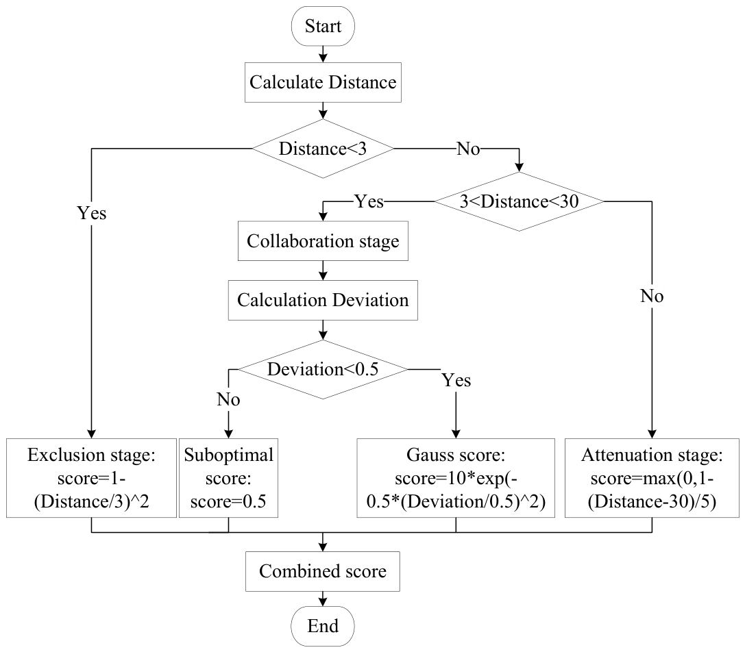
is the normalized value of the distance fraction between the leader ROV and the follower ROV. The
score calculation process is shown in
Figure 4.
First, the inter-ROV distance to the leader is evaluated. If this distance is less than 3 m, the algorithm enters a repulsion stage and outputs a corresponding repulsion score. For distances between 3 m and 30 m, the algorithm operates in the collaborative stage. In this stage, the deviation from the prescribed optimal separation is computed: if the deviation exceeds 0.5 m, a suboptimal score is assigned; otherwise, a Gaussian score is calculated such that the score increases as the deviation decreases. For distances exceeding 30 m, the algorithm transitions to an attenuation stage, wherein the score diminishes monotonically with increasing distance. The resulting trajectory score influences the objective function by adjusting the relative weighting among orientation, obstacle clearance, velocity, and inter-ROV cooperation terms—higher trajectory scores correspond to configurations better aligned with mission requirements. Based on this augmented DWA formulation, the optimal trajectory is generated and transmitted to the tracking controller in real time.
The establishment of the threshold range of 3 to 30 m is not solely based on sensing coverage considerations; the 3 m threshold is employed as the minimum safe separation distance for multi-ROV cooperative formation, which is determined by integrating the physical dimensions of the ROV and the operational margin of the umbilical cable, and by which inter-ROV collisions and cable entanglement can be effectively avoided. Meanwhile, the upper limit of the threshold is set to 30 m to be matched with the other three objective functions in this paper, so that the collaborative coordination of the overall optimization objective can be realized through weight allocation among multiple objective functions.
Sensitivity analysis has been conducted over the threshold range of 27 to 33 m, and it is demonstrated that the scanning coverage of multi-ROV cooperative perception and formation stability are maintained at a favorable level with no significant fluctuations within this interval, whereby the rationality of adopting 30 m as the threshold is validated.
Owing to its smooth decay characteristic, the evaluation score can be dynamically adjusted by the Gaussian scoring function in accordance with the cooperative distance, so that the smoothness of formation trajectory planning is guaranteed.
4. Simulation Results and Analysis
In this paper, the Falcon ROV is used as the simulation prototype. The hydrodynamic parameters of the Falcon are shown in
Table 1.
The Falcon consists of five thrusters, namely, four horizontal thrusters
and one vertical thruster
. The ultimate output torque of the thruster is 550 N. The relationship between the resultant force and resultant moment of the four degrees of freedom and the thruster is as follows:
In Formula (
25),
represents the angle between the thruster arrangement and the X-axis direction, with an angle of 36°.
,
m,
m.
4.1. Trajectory Planning Simulation
In the trajectory planning phase, the last known position of the shipwreck is taken as m, where the surface search vessel loses contact. Based on the historical ocean current direction at this location, a fixed deployment heading of 45° is adopted for the ROV search operation. For the multi-ROV scenario, each vehicle is assigned a nominal search radius of 10 m. Initially, the leader and the two follower ROVs, denoted A and B, are all deployed at the origin m. Considering the potential drift of the shipwreck, the estimated planar coordinates of the search terminus are set to m. To prevent redundant coverage, the improved DWA algorithm directs follower A to prioritize a waypoint at m based on its search radius, while its final target is correspondingly shifted to m. Similarly, follower B is guided to prioritize m, with its final target shifted to m, thereby establishing zoned coverage. In the simulation, the actual shipwreck position is placed at m.
In Equation (
6), the weight coefficients
,
,
, and
adopted in this study are set as
,
,
, and
. The individual components of the objective function are normalized prior to weighted summation.These values are designed to balance the formation coverage efficiency and collision avoidance requirements in the simulation search scenarios.The sampling rate of DWA is set at 0.1 s, and the prediction time domain is 3 s.
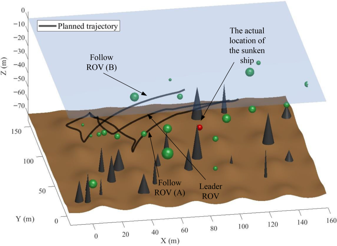
The trajectory generated by the conventional DWA is shown in
Figure 6. The actual shipwreck location is marked by red circles, and obstacles are classified into two distinct categories: conical seabed reefs and circular floating objects. As can be observed in
Figure 6, the planned trajectories exhibit redundant coverage of task areas and fail to locate the shipwreck. This limitation arises because the DWA accounts only for heading, obstacle proximity, and velocity when generating paths between the start and target points. Although the point-to-point planning task is nominally completed, the absence of inter-vehicle coordination results in excessive search overlap, limited overall efficiency, and ultimately the failure of ROV(A) to detect the shipwreck within its assigned search radius.
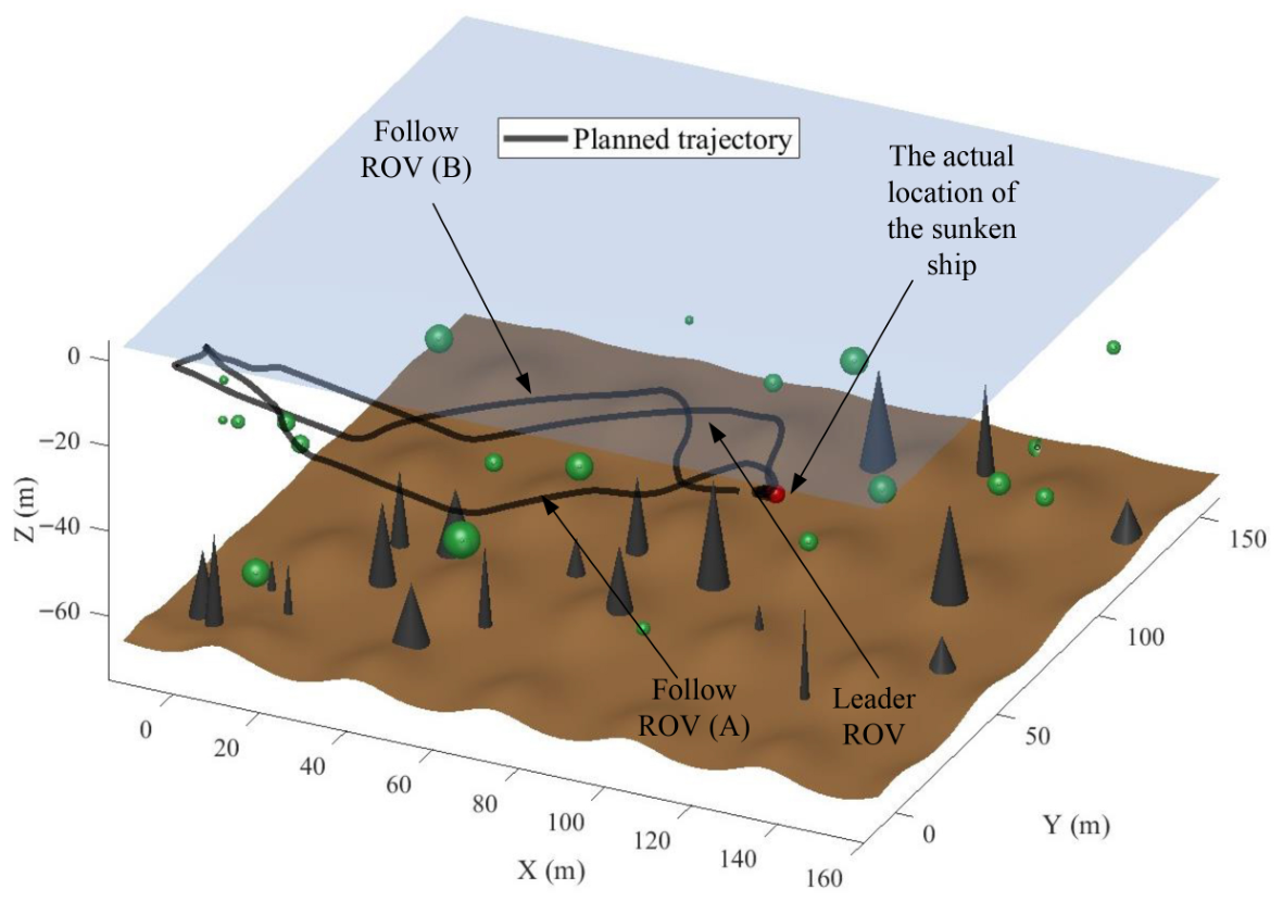
The trajectory planning after optimizing the DWA objective function is shown in
Figure 7. It can be observed from
Figure 7 that the search area is significantly expanded, and the positions of sunken ships are successfully located. This can be attributed to the fact that in the DWA objective function optimization process, when planning the trajectory of the starting point and the target point, not only the azimuth, obstacle and speed factors are considered, but also the search-cooperation in the multi-ROV scenario is considered. ROVs are prompted to maintain a certain distance from each other by the distance penalty function. Thus, not only is the trajectory planning from the start to the target point achieved, but also the search range is expanded and the search efficiency is improved.
4.2. Tracking Control Simulation
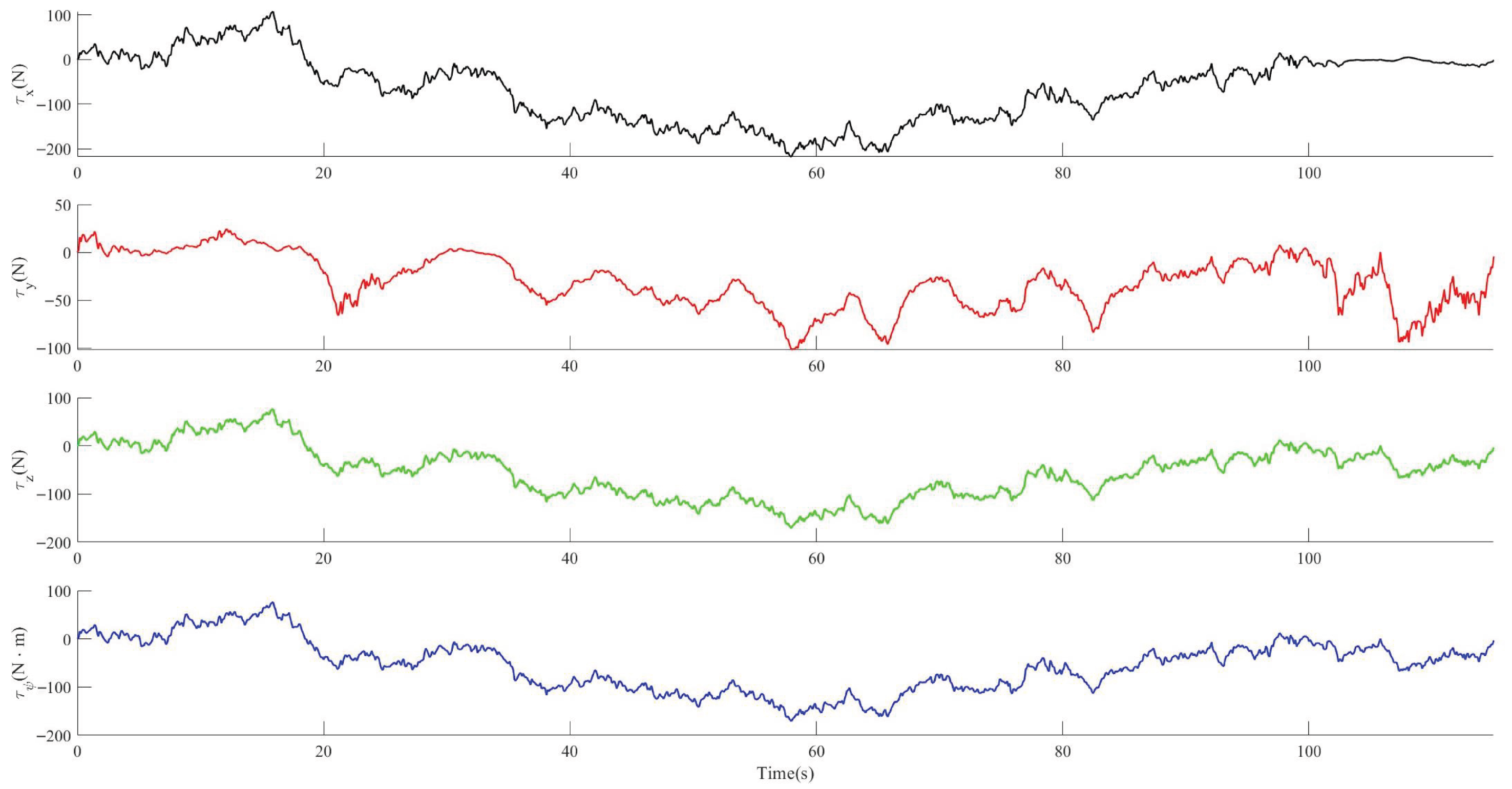
Due to the uncertainties in the marine environment, certain disturbances will occur to ROVs. Therefore, the impact of disturbances on the tracking control of ROVs needs to be considered. The Band-Limited White Noise module in Simulink is used to generate random noise with specific power spectral density to simulate random disturbances in the marine environment, such as water flow and waves. White noise represents a class of worst-case disturbances characterized by a relatively uniform energy distribution. If the trajectory tracking control of ROV can achieve stable convergence under Band-Limited White Noise excitation and enable the ROV to complete its search mission, it will also exhibit favorable tolerance to structured disturbances in real operating environments. In other words, the white noise model provides a moderately conservative yet effective test benchmark. Through (
26), the random noise is amplified and converted into the disturbing force with practical physical significance.
In Formula (
26),
R is the amplification matrix,
N is the random noise generated by the Band-Limited White Noise module,
M is the ROV inertial matrix,
B is the current state information matrix of the ROV.
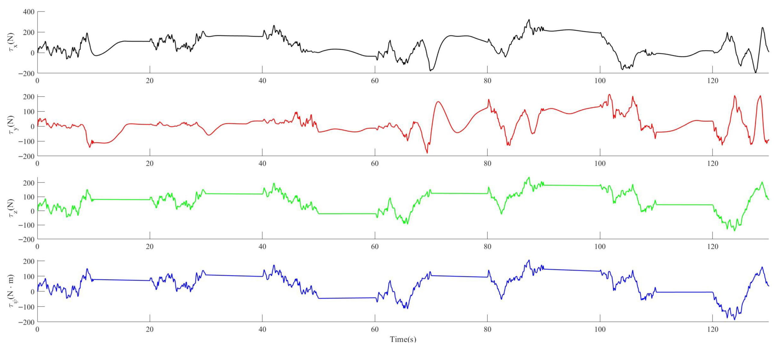
The perturbation curve used for time-varying disturbances is shown in
Figure 8.
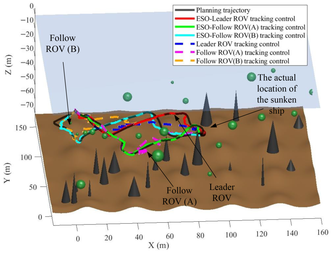
A comparison of the tracking effect of three-dimensional feedforward compensation for ROVs under time-varying disturbances is in
Figure 9.
In the MPC controller, the core parameters of MPC are , , and sampling time . In the ASMC controller, the constant gain coefficient . In the ESO, the observer bandwidth is set to , and the feedback gains are designed as , , , based on the parameterization of the observer bandwidth.
As shown in
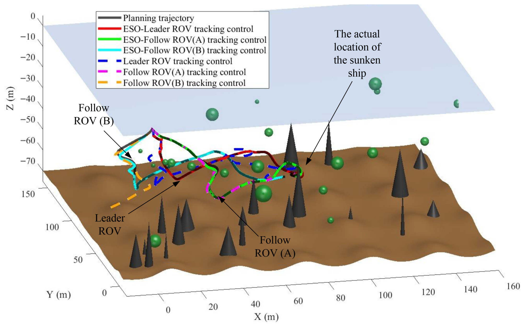
Figure 9, the presence of time-varying disturbances prevents the ROVs from accurately tracking the planned trajectories, leading to noticeable overshoot. Consequently, both the leader and the follower ROVs exhibit degraded tracking performance. In particular, follower ROV(B) lacks disturbance feedforward compensation, resulting in progressive error accumulation and eventual divergence from the prescribed path. Such behavior renders this control scheme impractical for field deployment.
In contrast, as shown in
Figure 9, the proposed ESO-based feedforward compensation proactively estimates the time-varying disturbances. Consequently, all three ROVs track the prescribed trajectories with high fidelity and exhibit no discernible deviation.
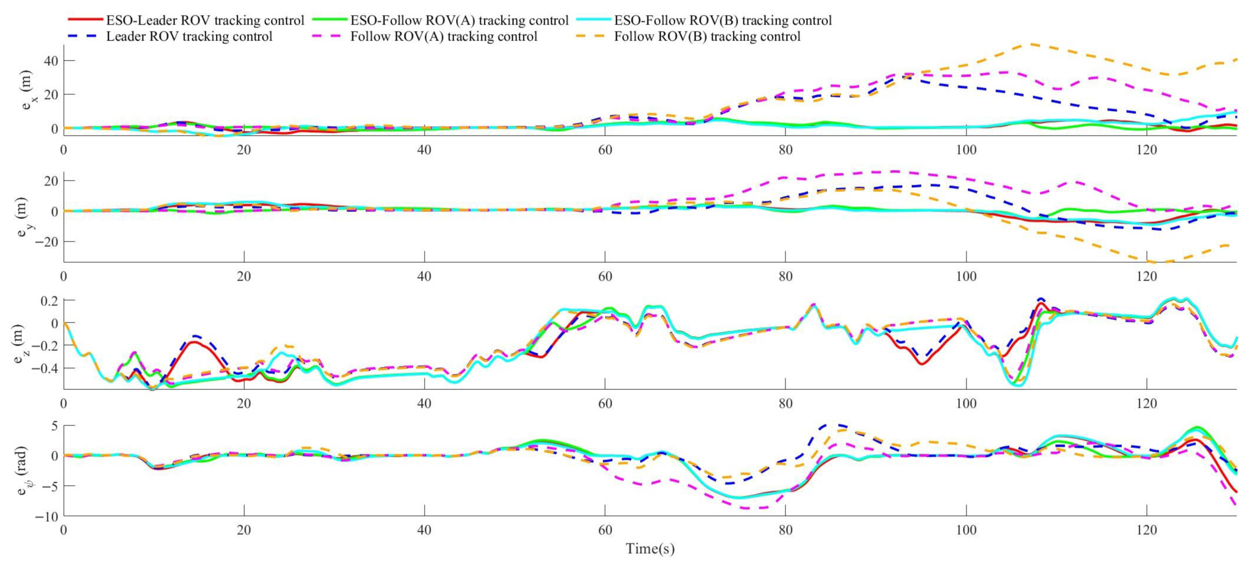
The tracking error curves of three-dimensional ROVs with and without ESO for feedforward compensation under time-varying disturbances are shown in
Figure 10.
The comparison of the maximum tracking error of each degree of freedom with and without ESO is shown in
Table 2.
In
Table 2, data exhibiting significant differences in tracking error are highlighted in blue. As shown in
Figure 10 and
Table 2, the control system without ESO-based feedforward compensation can eventually drive the tracking error toward zero after prolonged transient adjustment. However, in obstacle-dense regions, the adverse effects of disturbances are amplified, and the cascaded MPC–ASMC controller fails to respond with sufficient speed and precision, resulting in noticeable overshoot and obstacle collisions. In contrast, the system with ESO feedforward compensation not only achieves comparable steady-state error reduction, but also effectively mitigates disturbance impacts in cluttered environments. Consequently, the augmented cascaded controller—incorporating ESO-based feedforward compensation—delivers timely and accurate trajectory corrections, substantially improving tracking fidelity in challenging scenarios.
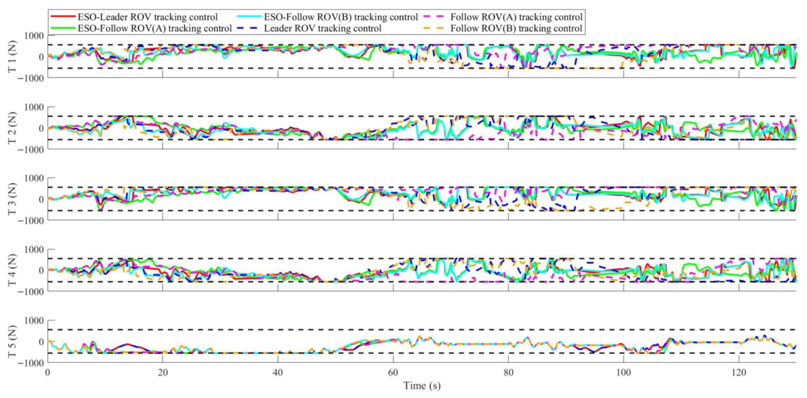
The thrust output curves of the five thrusters under time-varying disturbances, with and without ESO and with combined ESO feedforward compensation, are shown in
Figure 11.
The maximum thrust output of each thruster in the two cases of no ESO and combined with ESO feedforward compensation under time-varying disturbances is shown in
Table 3.
Since the maximum thrust values of the thrusters are all 550 Newtons, it is necessary to calculate the proportion of the torque generated when the thrust exceeds the limit during this tracking control process, as shown in
Table 4.
For the Falcon ROV, the maximum thrust output of an individual thruster is 550 N. As shown by the thrust response curves in
Figure 11 and the quantitative summary in
Table 4, the two control schemes produce markedly different thrust saturation profiles. With ESO feedforward compensation, operation at the 550 N saturation limit is rare: even the most heavily saturated thruster remains at the limit for only 10.30% of the total operating duration, and the saturation events are brief. The majority of thrusters exhibit no saturation whatsoever. In contrast, without ESO compensation, all thrusters operate against the 550 N saturation bound for a substantial portion of the mission; the thruster experiencing the most severe saturation is constrained at the limit for 77.63% of the operating time. This confirms that, in the absence of ESO feedforward compensation, the system operates under prolonged thrust saturation. The proposed scheme enables all three ROVs to successfully complete the tracking task under time-varying disturbances while reducing the frequency of thrust saturation events by up to seven times. In contrast, under the conventional MPC–ASMC controller, one ROV deviates from the formation and fails to complete the tracking task. Under abrupt disturbances, the proposed approach reduces the trajectory tracking error by up to six times and decreases the frequency of thrust saturation events by up to four times.
Prolonged thrust saturation renders the trajectory tracking control system of the leader ROV unable to accurately track the reference trajectory planned by the DWA algorithm. The feedback controller continuously outputs large-magnitude error correction commands but fails to achieve real-time and effective adjustments to the ROV’s pose. As tracking errors accumulate, the ROV gradually deviates from the preset trajectory planning path, ultimately leading to the failure of the trajectory tracking task.
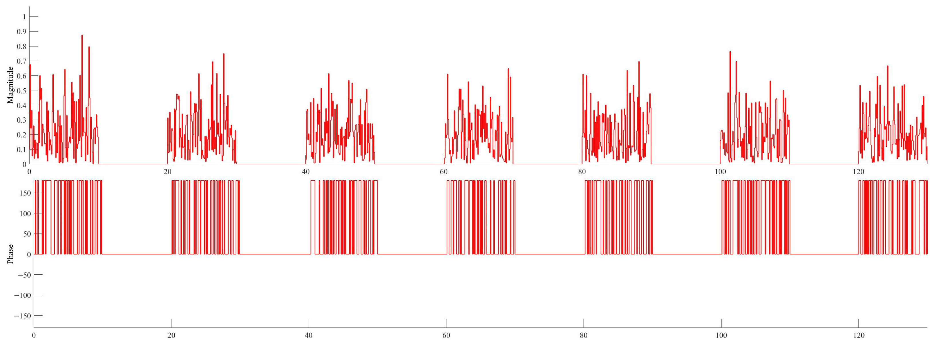
For the perturbation of mutations, simulations were conducted using the random number generator module and pulse generator module in Simulink. The generated amplitude–phase spectrogram is shown in
Figure 12.
The generated random pulses are transformed and amplified through (
26), and the resulting mutant perturbations are shown in
Figure 13.
Figure 14 compares the tracking performance of the multi-ROV formation under DWA-based trajectory planning in the presence of abrupt marine disturbances. With ESO feedforward compensation, only minor transient deviations from the planned trajectory are observed, and the tracking error is corrected rapidly. In contrast, the system without ESO compensation exhibits substantial tracking deviations, which lead to formation distortion, unnecessary path detours, and error amplification due to disturbance accumulation; moreover, the recovery time required to realign the actual trajectory with the planned path is considerably longer. These results confirm that ESO-based feedforward compensation provides effective real-time disturbance estimation and attenuation, substantially enhancing trajectory tracking accuracy under abrupt disturbance conditions.
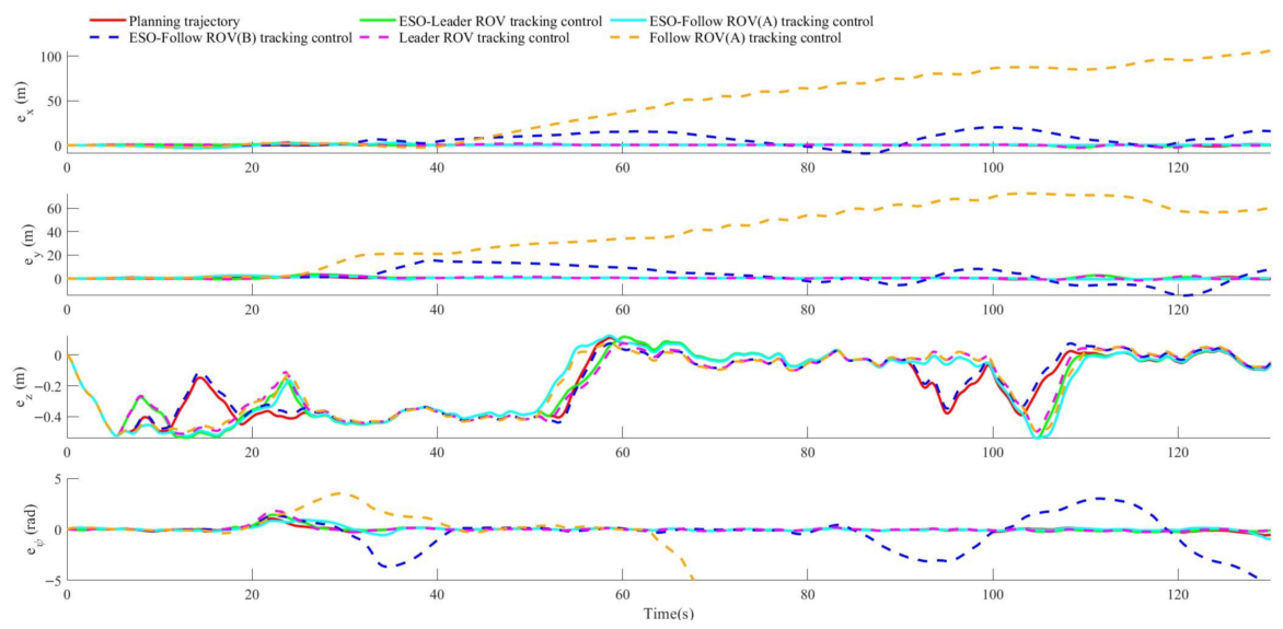
The tracking error curves of ROV under mutation interference without combining ESO with ESO feedforward compensation are shown in
Figure 15.
The comparison of the maximum tracking error of each degree of freedom with and without ESO is shown in
Table 5.
As shown in
Figure 15 and
Table 5, the cascaded MPC–ASMC controller without ESO feedforward compensation fails to provide timely dynamic correction for trajectory deviations and external disturbances under the imposed thrust constraints. Error accumulation consequently leads to large-amplitude tracking overshoot and substantial performance degradation. For both the leader and follower ROVs, the maximum tracking error recorded without ESO compensation is approximately six times greater than that achieved with ESO feedforward compensation, rendering the former scheme impractical for precise ROV tracking applications.
In contrast, the proposed system with ESO feedforward compensation effectively suppresses external disturbances across all operating conditions and achieves the asymptotic convergence of tracking errors via closed-loop regulation. By providing real-time disturbance estimation and feedforward compensation, the ESO enables the cascaded MPC–ASMC controller to rapidly and accurately correct trajectory deviations, mitigate performance degradation induced by thrust constraints, and prevent severe tracking overshoot. Consequently, the overall trajectory tracking accuracy and robustness are substantially enhanced under the combined effects of actuator saturation and complex environmental disturbances.
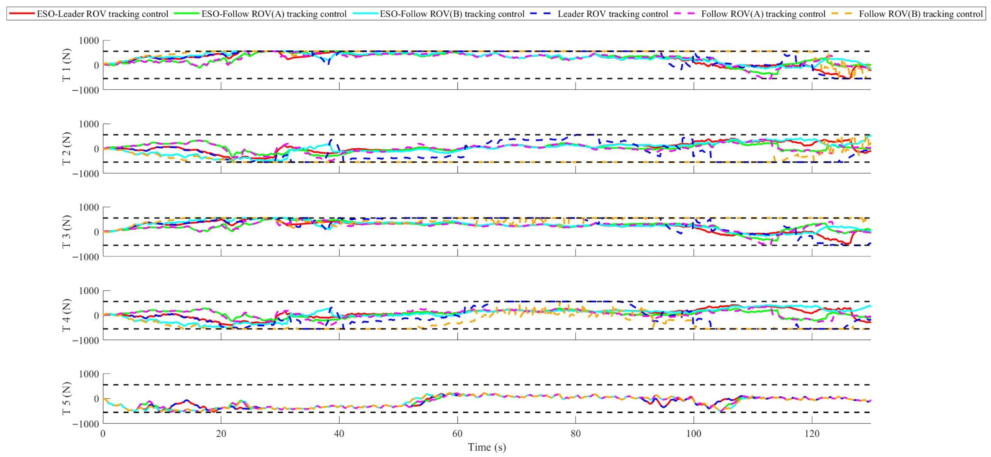
The maximum thrust outputs of each thruster with and without ESO in three-dimensional mutation perturbation are shown in
Figure 16.
The maximum thrust outputs of each thruster under three-dimensional mutation disturbances, with and without ESO feedforward compensation, are shown in
Table 6.
Since the maximum thrust values of the thrusters are all 550 Newtons, it is necessary to calculate the proportion of the torque generated when the thrust exceeds the limit during this tracking control process, as shown in
Table 7.
Actuator thrust saturation constitutes a critical constraint that degrades ROV trajectory tracking performance in unknown underwater environments. For the Falcon ROV employed in this study, the maximum thrust output of an individual thruster is limited to 550 N. As evidenced by the quantitative results in
Figure 16 and
Table 7, the control schemes with and without ESO feedforward compensation exhibit markedly different thrust saturation characteristics. With ESO compensation, the incidence of thrust saturation is substantially reduced: the most heavily loaded thruster operates at its saturation limit for only 14.30% of the total duration, and the saturation events are brief in duration.
In stark contrast, the system lacking ESO compensation experiences severe and persistent thrust saturation. For the most overloaded thruster, up to 50.96% of the operating time is spent constrained at the 550 N limit. Such prolonged saturation prevents the leader ROV from accurately tracking the DWA-generated reference trajectory. Under these conditions, the feedback controller issues large-amplitude corrective commands but lacks the capacity for effective real-time pose adjustment, leading to progressive tracking error accumulation and, ultimately, mission failure. The underlying mechanism for this improvement is straightforward: the ESO provides real-time observation and feedforward compensation of unknown environmental disturbances, thereby alleviating the control burden on the baseline MPC–ASMC controller and reducing the required thrust amplitudes.
Continuous thrust saturation renders the trajectory tracking control system of the leader ROV unable to accurately track the reference trajectory planned by the DWA algorithm. The feedback controller can only continuously output large-amplitude error correction commands, yet fails to achieve real-time and effective adjustment of the ROV’s pose. With the continuous accumulation of tracking errors, the ROV gradually deviates from the preset trajectory planning path, ultimately leading to the failure of the trajectory tracking task.