Article

AUV Path Planning Method for Underwater Moving Target Search Based on a Target-Position-Controlled Mutation Strategy Genetic Algorithm


1
National Key Laboratory of Underwater Acoustic Technology, Harbin Engineering University, 145 Nantong Street, Harbin 150001, China
2
Key Laboratory of Marine Information Acquisition and Security (Harbin Engineering University), Ministry of Industry and Information Technology, 145 Nantong Street, Harbin 150001, China
3
College of Underwater Acoustic Engineering, Harbin Engineering University, 145 Nantong Street, Harbin 150001, China
4
College of Information and Communication Engineering, Harbin Engineering University, 145 Nantong Street, Harbin 150001, China
*
Author to whom correspondence should be addressed.
J. Mar. Sci. Eng. 2026, 14(9), 805; https://doi.org/10.3390/jmse14090805
Submission received: 17 March 2026 / Revised: 14 April 2026 / Accepted: 24 April 2026 / Published: 28 April 2026
(This article belongs to the Section Ocean Engineering)

Abstract

To accomplish underwater search missions of the target with stochastic motion, path planning is required prior to autonomous underwater vehicle (AUV) operations. Genetic algorithms (GAs) are a classical approach for target search path planning; however, when applied to moving underwater targets, they often rely on oversimplified motion models and lack flexible mutation direction control, resulting in suboptimal search paths and reduced detection performance. To address these limitations, this paper proposes a GA-based path planning method incorporating a target-position-controlled mutation strategy. First, a Markov process combined with a grid-based approach is used to model stochastic target motion and derive the spatial probability distribution of target positions. Second, based on the target distribution grid, the influence of random fluctuations on sonar signals is simulated to construct a probabilistic detection model. Finally, the target distribution and detection probability model are integrated into the proposed GA to generate an optimal AUV search path. Simulation results show that the proposed method effectively improves path planning for moving targets under stochastic conditions, increasing the target cumulative detection probability from 0.33 to 0.48.

1. Introduction

Autonomous underwater vehicles (AUVs) play a crucial role in underwater safety, marine exploration, and target detection due to their high autonomy and operational flexibility [1,2,3,4]. They are widely applied in tasks such as search and rescue [5], environmental perception [6], target tracking [7], reconnaissance [8], and other operations. To improve the success rate of target search missions, it is essential to plan the AUV navigation path prior to operation. Path planning aims to determine an optimal trajectory that enables mission execution according to specified performance criteria, while satisfying environmental constraints and vehicle capabilities [9].
In path planning, a key challenge is ensuring the validity of the planned path through the proper incorporation of multiple constraints [10]. These constraints can be broadly classified into two categories. The first category involves environmental and target constraints, such as the operational area in environmental perception, target motion characteristics in tracking tasks, and target types in detection scenarios [11]. The second category concerns the intrinsic capabilities of the AUV, including energy consumption, sensor performance, and navigation accuracy [12]. Most current studies primarily focus on the first category, with comparatively limited attention given to constraints arising from the AUV’s own capabilities. However, these intrinsic factors directly influence the accuracy of path planning and, consequently, the overall mission success. Therefore, investigating path planning under AUV capability constraints is important.
For underwater moving target search tasks, the sonar system, as the primary sensing device of an AUV, directly determines target detection performance. Consequently, path planning that explicitly accounts for sonar system performance represents an important research direction in this field [13]. Path planning in this paper refers to determining an appropriate search region and corresponding path based on prior information, such as the target’s initial position, heading range, and speed range, while also considering constraints related to sonar detection capability in the underwater environment. The objective is to derive an optimal search path for AUV-based target detection tasks [14]. Accordingly, the problem of underwater moving target search path planning can be formulated as a constrained optimization problem. Optimization algorithms, owing to their stochastic global search capability, play a significant role in solving such optimization problems.
Optimization algorithms constitute the core of path planning, and different methods are applicable under different constraints. For instance, geometric model-based search algorithms [15] are suitable for static and global path planning, but their computational burden becomes significant in dynamic environments or high-dimensional problems. The artificial potential field method [16] is widely used for dynamic obstacle avoidance in AUV path planning due to its simplicity and computational efficiency, however, it is prone to local minima. Heuristic algorithms [17,18,19] are commonly adopted for global path planning tasks such as target tracking and search. Although they provide strong exploration capability and can approximate globally optimal solutions, they often suffer from complex structures and high computational cost, requiring adaptation to specific constraints [20]. Heuristic algorithms include particle swarm optimization [21], genetic algorithms [22], and artificial neural networks [23]. Among them, ant colony optimization is computationally intensive, while neural networks rely heavily on large-scale training data [24]. In contrast, genetic algorithms are widely used in target search path planning [25]. They employ a probabilistic selection mechanism inspired by the principle of “survival of the fittest”, transforming the problem into a mathematical optimization model and iteratively evolving candidate solutions [26,27]. Due to their stable structure, strong global optimization capability, and efficient search performance, genetic algorithms are well suited for underwater moving target search [28], where the objective is to identify the path with the highest detection probability among multiple candidates. Consequently, they have been extensively applied in AUV path planning for target search tasks.
Target search path planning based on genetic algorithms primarily involves environmental modeling, search path modeling [29,30], multi-algorithm fusion [31,32], and genetic strategy improvement [33]. However, directly applying the classic genetic algorithm to moving target search path planning leads to issues such as oversimplified environmental modeling, high computational cost, and ineffective genetic strategies. Underwater terrain and the acoustic environment affect target motion and sonar detection performance. Establishing accurate models of the environment, target motion, and sonar detection can improve the reliability of path planning. To address environmental and sonar detection modeling, Jung-Hong Cho [34] and Kierstead [35] performed search path planning under sonar detection constraints based on terrain analysis of the search area. However, they did not consider the influence of underwater random fluctuations or target position distribution on sonar detection efficiency. Regarding the path planning algorithm, to overcome the problems of high computational cost and the inability to adaptively control the direction of population mutation, Sahoo [36] and Lu [37] combined the genetic algorithm with the grey wolf optimizer. They improved computational efficiency by modifying the population usage rules of the genetic algorithm. Nevertheless, the increased number of algorithm parameters makes parameter tuning difficult, requiring a trade-off between algorithm fusion and parameter setting. Fan [38] and Roberge [39] introduced an adaptive mutation factor to adjust the mutation direction of the path population. This approach offers advantages in global optimization; however, it requires real-time monitoring of population fitness changes, which increases computational overhead. Therefore, a genetic algorithm for underwater moving target search path planning requires determining the optimal path based on an accurate environmental model and an optimized genetic strategy.
During underwater moving target search operations, AUVs use sonar systems to receive sound waves reflected or emitted by targets and to complete target detection and identification [40,41]. In the path planning stage, the uncertainty of target motion and the sonar detection capability are two important constraints that must be considered. On one hand, the uncertainty of target motion causes the target to move randomly within the operational area, affecting the probability distribution of its position. This, in turn, leads to inaccurate estimation of sonar detection probability and reduces the reliability of the search path plan. Therefore, the search path planning problem imposes higher demands on target motion modeling. In response, Caiti [42] developed a target information database simulation system in which users can select target parameters from the database and simulate target motion using the Monte Carlo method. Baxendale [43] used stochastic differential equation theory to describe the target motion process but did not consider the influence of motion process noise on target behavior. On the other hand, sonar detection capability is a key constraint in search path planning [44]. Owing to the complex and variable underwater environment, sonar detection is easily affected by external factors [45]. To address this issue, most studies have considered the impact of sonar detection on AUV search path planning only under simplified conditions [46]. Jung-Hong Cho [47] examined the influence of the underwater acoustic environment at different locations on sonar signal margin but did not account for the effect of underwater random fluctuations on that margin. Consequently, modeling target motion and sonar detection capability is essential for achieving effective underwater target search through path planning.
Therefore, this paper addresses the AUV search path planning problem under conditions of target motion uncertainty and stochastic fluctuations in sonar detection performance. To this end, an improved genetic algorithm is proposed, with enhancements to both the workflow and mutation strategy to achieve effective path planning. The remainder of this paper is organized as follows. Section 2 establishes a probabilistic model of target position distribution by simulating target motion using stochastic processes and analyzing its spatial distribution within the search area. Section 3 develops a sonar detection probability model, in which the detection performance at each node is evaluated and both instantaneous and cumulative detection probabilities are formulated; these are incorporated as constraints in the path planning process. Section 4 presents the improved genetic algorithm for moving target search, where the mutation strategy is refined based on the target position distribution and sonar detection probabilities to overcome low search efficiency and premature convergence in conventional genetic algorithms. Section 5 validates the proposed method through simulations, and Section 6 concludes the paper.

2. Establishment of Moving Target Position Distribution Probability Model

From the perspective of pre-mission path planning for AUV target search, only prior information—such as the target’s initial position and heading range—is available, and the target’s real-time position cannot be determined. Moreover, underwater target motion is influenced by ocean currents, including their direction and velocity, which introduces additional uncertainty. In evaluating path planning performance, detection probability is a key metric, defined as the product of the target distribution probability and the sonar detection probability. Therefore, to accurately assess path planning quality, it is necessary to establish a probabilistic model of the moving target’s spatial distribution prior to planning. It should be noted that the search is conducted within regions where the target is likely to be present. The target’s motion is not entirely unknown; rather, partial information—such as its initial position, heading range, and speed range—is available. Accordingly, the target distribution probability model is constructed based on this prior information.

2.1. Target Trajectory Probability Model

To characterize the distribution of uncertain target positions, the evolution of the target state is modeled as a stochastic process. Assuming that the target motion is independent of the AUV search strategy and that its position at a given time depends only on its state at the previous time step, the target dynamics can be described as a Markov process. Specifically, given the current position of the target, its subsequent position can be predicted based on the prior information on velocity and heading angle ranges. The Markovian description of target motion is expressed in Equation (1).
P m t = F P m t Δ t + q
where Δ t represents the time interval between two sampling moments. P m t represents the two-dimensional position of the target. F is the state transition matrix, represents motion pattern of the target from the previous moment to the present moment. q represents the noise of the target motion process, which follows the two-dimensional normal distribution. The initial moment position is the target initial position in the prior information.
Due to the uncertainty of underwater target motion, the state transition matrix of the Markov process in (1) is difficult to obtain analytically. Considering that underwater targets typically exhibit low speed and slowly varying heading angles, a constant-velocity (uniform linear motion) assumption is introduced. Accordingly, the target position update is simplified as the sum of the previous position and the product of velocity and time step, as expressed in (2). Based on this assumption, a Monte Carlo method is employed. Using the mean and variance of velocity and heading angle from prior information, multiple sets of these parameters are randomly sampled according to a normal distribution to generate a set of possible target trajectories. In this way, the discrete constant-velocity model approximates the original complex Markov process, effectively capturing motion uncertainty while avoiding the need to explicitly solve the state transition matrix. The specific generation method of the target trajectory is as follows.
According to the initial position, mean and variance of speed and heading angle of the target, n groups of speeds and heading angles are randomly generated according to the normal distribution trend, and n trajectories are generated according to the method described in Equation (2). The probability of target moving along each trajectory is equal. The probability of the target on each trajectory is 1 / n , and the sum of probabilities is equal to 1. In this way, the Monte Carlo method is used to facilitate the transformation between the state transition matrix and the target trajectory.
P i m t = P i m t Δ t + v i Δ t + q
where v represents the two-dimensional velocity calculated based on the target speed and heading angle. i represents the i target trajectory.
According to the simulation method of the trajectory described above, the sampled speed and heading angle sets follow a normal distribution. From the AUV’s perspective, given prior information on the target’s initial position as well as its speed and heading angle ranges, the potential region in which the target may appear can be approximated as a sector-shaped area bounded by the heading angle limits.

2.2. Target Position Distribution Probability Model

In the trajectory simulation described above, similar speed and heading values may lead to nearly identical target positions. For example, when the speed is 2 m/s and 2.2 m/s, and the heading is 30° and 32°, respectively, the resulting target positions at t = 60   s differ only marginally. If the position is computed at every time step, this can lead to substantial redundant calculations. Moreover, targets within the sonar detection range can be detected without requiring continuous, high-frequency evaluation. Therefore, a grid-based approach is adopted to construct the target position distribution probability model (as illustrated in Figure 1). The main steps are as follows:
a.
Take the target initial position as the origin. Divide the target presence area into M × N grids with equal spacing and no overlapping points.
b.
n target tracks are drawn in M × N grids in the order of sampling time (as shown by the left dot in Figure 1).
c.
Count the number of targets in different grids simultaneously, such as the number of red dots in various grids on the left side of Figure 1.
d.
According to the number of targets in each grid calculated in step c, the probability of the target’s position in each grid is determined. That is, there are several dots in the same grid at the same time, and the target position distribution probability of the grid is several parts of n (as shown in the blue grid at the bottom of Figure 1).
According to the above procedure, the continuous space problem is transformed into a discrete representation, where target motion within the region is approximated by transitions between grid cells. It should be noted that finer grid resolution yields higher accuracy in the estimated probability distribution, but at the cost of increased computational complexity. This trade-off will be further discussed in the following sections.
By combining the trajectory model in Equation (2) with the position distribution framework shown in Figure 1, trajectory samples are mapped onto the grid, and the target position distribution probability at each sampling time is obtained. Let the target position distribution probability at time t is denoted as P t , as defined in Equation (3).
P t = P t 11 P t 12 P t 1 N P t 21 P t 22 P t 2 N P t M 1 P t M 2 P t M N
where P t i j ( i = 1 , , M , j = 1 , , N ) represents the target position distribution probability in the i row and j column grid at the time t , and has P t i j 0 , i = 1 M j = 1 N P t i j = 1 .

3. Establishment of Sonar Detection Probability Model

Sonar systems are commonly employed for target detection in AUV search missions. The probability of detection is influenced by both environmental conditions and the sonar operating mode. Therefore, for path planning in moving target search, it is essential to account for the sonar operating characteristics and environmental effects. This necessitates the incorporation of a sonar detection probability model into the path planning framework.
The objective of this section is to construct such a model. The search area is first discretized using a grid-based approach, and the sonar SE at each grid node is computed based on the sonar equation. Subsequently, the cumulative detection probability (CDP) is derived by integrating the sonar signal excess with the target position distribution probability. The CDP is then used as a performance metric for evaluating path planning strategies.

3.1. Sonar Detection Signal Excess Model Based on λ σ Model

In general, to avoid the AUV being detected during detection, passive sonar is often used for detection. Unlike active sonar, passive sonar does not emit acoustic signals but detects targets by receiving the noise or sound radiated by them. However, the sonar detection effect varies at different locations within the area due to the influence of the underwater environment. That is, the sonar detection capability varies in different sub-grids in Figure 1. Therefore, it is necessary to analyze the sonar detection capability in various sub-grids for path planning. In this study, the SE is adopted as a metric to quantify detection performance. By computing the signal excess for each grid cell, the sonar detection probability can be efficiently evaluated, thereby reducing computational complexity. The calculation of the passive sonar signal excess is given as follows [48]:
F O M = S L N L + D I D T
S E = F O M T L
where S L represents the source level. N L refers to the environmental noise level. D I is the sonar reception directivity index. D T is the detection threshold. T L refers to the loss of acoustic signal propagation. S E is the sonar detection signal excess.
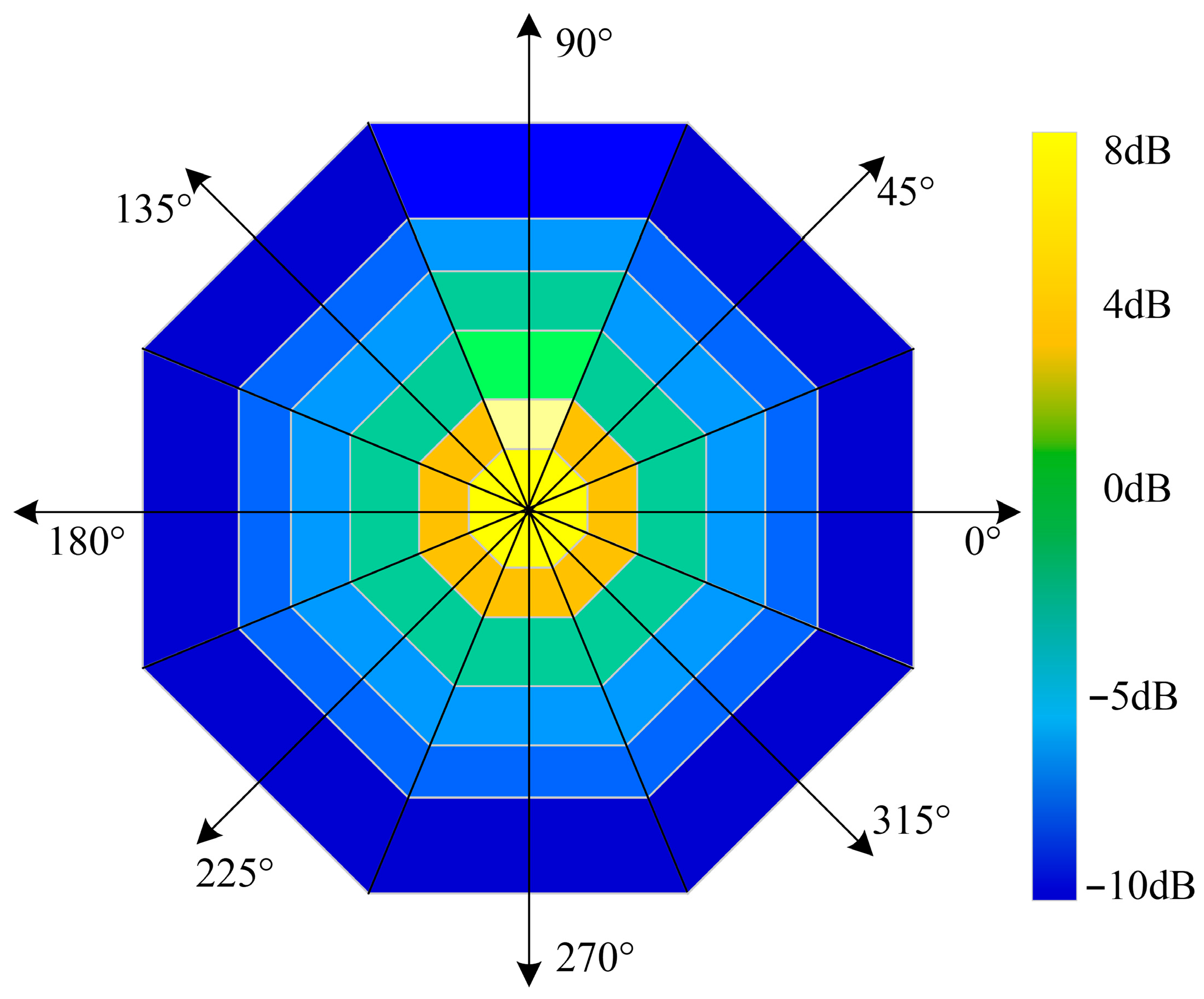
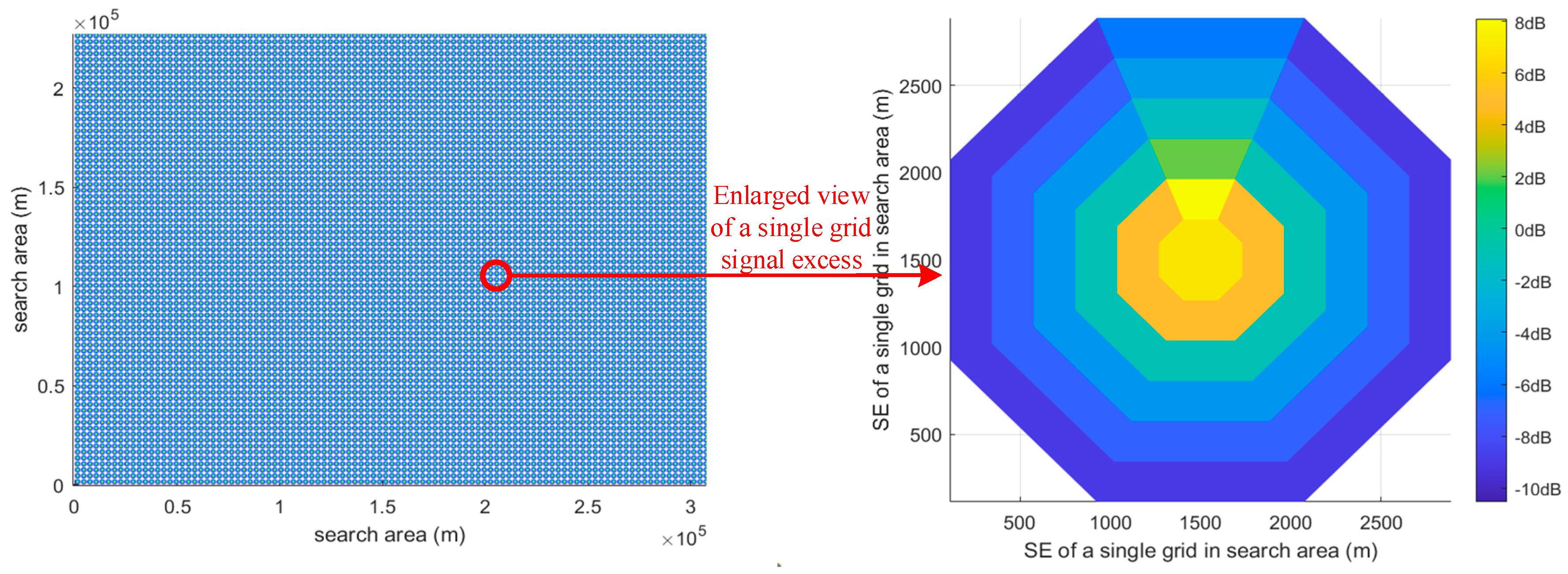
Due to the directivity of sonar receivers, variations in the relative azimuth between the sonar and the target lead to differences in the SE. Therefore, it is necessary to analyze the SE in multiple directions around the sonar system. Although sonar directivity varies continuously with azimuth, this variation is relatively small compared with acoustic propagation loss, resulting in only minor differences in SE for adjacent directions. Considering the symmetry of the sonar beam pattern, using an excessive number of directions yields limited improvement in detection accuracy while significantly increasing computational cost. Conversely, restricting the analysis to only four directions neglects oblique detection characteristics, leading to an incomplete representation of detection capability. To balance accuracy and computational efficiency, this paper evaluates the SE at discrete distance intervals along eight radial directions centered on the sonar system, as illustrated in Figure 2. This approach enables an accurate representation of the AUV’s detection capability within each grid cell. It should be noted that, in Figure 2, the sonar signal excess is calculated under the assumption that the target is located at an azimuth of 90° relative to the sonar system.
In Figure 2, different colors represent the magnitude of the SE, with values increasing as the color approaches yellow. The positive direction of the probe node x-axis is defined as 0°, with angles measured counterclockwise. Taking the sonar as the center, the surrounding 360° is evenly divided into eight sectors starting from 0°. The SE is then calculated at discrete distance intervals along radial directions every 45°, as indicated by the eight arrows in Figure 2. In addition, when the target is located at an azimuth of 90° relative to the sonar, the SE within the sector spanning ±22.5° around this direction reaches its maximum, indicating a high detection probability. As the target deviates from the principal detection direction, the SE decreases, resulting in a corresponding reduction in detection likelihood.
In addition to acoustic propagation loss and the sonar receiver directivity index considered in Equation (5), random fluctuations in the sonar signal excess caused by the underwater environment also affect detection performance and reduce accuracy. To more accurately characterize these effects, the λ σ model [34] is introduced to describe the random fluctuations in SE. The selection of this model is motivated by the following considerations. The λ σ process is formulated as a compound Poisson process, which remains constant between jump events; the occurrence times of jumps follow a Poisson distribution, while the amplitudes of the jumps are independent and identically distributed random variables. The sonar SE is a distance-dependent physical quantity that varies continuously under ideal conditions. In the absence of environmental disturbances, it follows the value determined by acoustic propagation loss. However, sudden noise disturbances in the underwater environment introduce random fluctuations. The occurrence of such disturbances is random in time, and each event induces a stochastic perturbation in the signal excess. This physical behavior is consistent with the characteristics of λ σ process. Accordingly, the random fluctuation in SE is modeled using this stochastic process, and the sonar signal excess model based on the model λ σ is as follows:
S E t ( t ) = S E ( t ) + ε ( t )
where S E t ( t ) represents the SE with random fluctuation at time t . S E ( t ) represents the margin of SE under ideal conditions. ε ( t ) represents random fluctuations following the jump process of λ σ . When no jump occurs, ε ( t ) = 0 . When there is a jump, the amplitude of the random fluctuation is described by a Gaussian distribution with a mean of 0 and a variance of σ 2 . The time of the jump follows a Poisson distribution with parameter λ , meaning the expected time between two adjacent jumps is 1 / λ .
Combined with the target position distribution probability model of the grid method in Section 2.2, the SE described in Figure 2 is the signal excess of the sub-grid center. The instantaneous detection probability is related to the SE and target position distribution probability. Therefore, analyzing the SE in each grid and combining it with the target position distribution probability is the foundation for calculating the detection probability. The specific calculation method will be discussed below.

3.2. Instantaneous Detection Probability and Cumulative Detection Probability of Sonar

Based on the target position distribution probability and the sonar signal excess, the influence of SE on search path planning can be more accurately characterized. Detection probability is adopted to quantify the sonar detection capability. It is categorized into instantaneous detection probability and cumulative detection probability, both of which are defined in detail as follows.

3.2.1. Instantaneous Detection Probability of Sonar

By combining the target position distribution at a given time with the SE corresponding to the AUV’s position at that time, the instantaneous detection probability can be determined. Specifically, based on the AUV’s position and the probability distributions of the target, the corresponding SE value is obtained. When the SE is greater than zero, the instantaneous detection probability of the sonar is computed using the statistical detection model, as expressed below:
P d t ( S E t ) = 1 2 π σ S E t e x 2 2 σ 2 d x
where P d t ( S E t ) represents the instantaneous detection probability of sonar without considering the target probability at time t . S E t is the sonar signal excess at time t .
Combining the target distribution probability, the instantaneous detection probability at time t in the area is:
P D t = i = 1 M j = 1 N P d t ( S E t ) P t i j
In this case, P t i j represents the target position distribution probability in the row i column j at time t .

3.2.2. Cumulative Detection Probability of Sonar

The instantaneous detection probability describes the likelihood of detecting a moving target at a specific time, determined by the target distribution and the corresponding SE at that moment. However, the objective of this study is to optimize the complete AUV search path. Therefore, to comprehensively evaluate search performance, the concept of cumulative detection probability (CDP) is introduced. CDP is defined as the probability that the sonar detects the target at least once along the entire search path, thereby reflecting the overall effectiveness of the path. During path execution, the sonar performs detection at discrete time intervals, yielding a sequence of instantaneous detection probabilities. The CDP is not obtained by simply summing these probabilities. Instead, assuming independent detection events, it is computed based on the probability of at least one successful detection. A higher CDP indicates a greater likelihood of detecting the target and, consequently, a more effective search path.
When consecutive detections along the search path are assumed to be independent, the CDP can be expressed as 1 1 P D i , i.e., the complement of the product of the individual detection failure probabilities. However, in practical underwater scenarios, targets typically move slowly and sonar directivity varies gradually. Consequently, instantaneous detection probabilities at adjacent time steps are positively correlated rather than independent. In other words, a high detection probability at a given moment implies a high likelihood at neighboring moments. Conventional independence-based models neglect this correlation, leading to inaccuracies in CDP estimation. To address this issue, the model incorporates the historical maximum of the instantaneous detection probability as a correction factor. In this formulation, the CDP depends not only on the current and past instantaneous probabilities but also on their historical maximum P D h . A larger historical maximum reduces the overall failure probability and increases the CDP. Even if subsequent detection probabilities decrease, the historical maximum continues to exert a dominant influence, significantly enhancing the cumulative detection performance. In addition, a detection correlation factor α is introduced to quantify the dependence between adjacent detections. Shorter time intervals correspond to stronger correlation and weaker independence, allowing the model to appropriately regulate the contribution of the historical maximum to the CDP.
Assuming 0 t T , the instantaneous detection probability at time t is P D t . The maximum value of all instantaneous detection probabilities before time t is P D h . The CDP at time t is C D P t .
C D P t = 1 1 P D h 1 α P D h i = 0 t ( 1 α P D i )
where α = 1 e λ Δ is the detection correlation factor, Δ is the time interval between two adjacent detections, T is the total search time.
When applying the grid-based approach to model target position distribution and sonar detection probability, the selection of grid size is critical. If the grid is overly refined (i.e., the values of M and N in Equation (8) are large), the spatial resolution of the target distribution is high, but the probability mass becomes dispersed across many cells. This significantly increases the number of grid evaluations, thereby raising the computational cost of both sonar detection probability estimation and the genetic algorithm. Conversely, if the grid is too coarse, the computational burden is reduced, but the target distribution becomes overly concentrated. In this case, the grid cannot accurately represent the potential target locations, leading to reduced reliability in both the target distribution probability and the sonar detection probability, which may ultimately degrade path planning performance. Therefore, a trade-off must be achieved between grid resolution and computational complexity. In practice, the grid size can be determined based on the maximum detection range of the sonar system. This ensures effective target detectability while minimizing redundant calculations and preserving sufficient accuracy in representing the target position distribution.

4. Genetic Algorithm Path Planning Based on Target Position Control Mutation Strategy

The solution space optimization capability of genetic algorithms (GAs) plays a crucial role in path planning. First, an initial population of candidate search paths is generated based on AUV motion parameters, forming the solution space for the optimization problem. Next, the CDP of each path is evaluated, and paths with higher CDP values are preferentially retained. Subsequently, crossover and mutation operations are applied to evolve the population. Through iterative updates of the population, the path with the highest CDP is ultimately selected as the optimal solution for path planning.

4.1. AUV Search Path Population Establishment

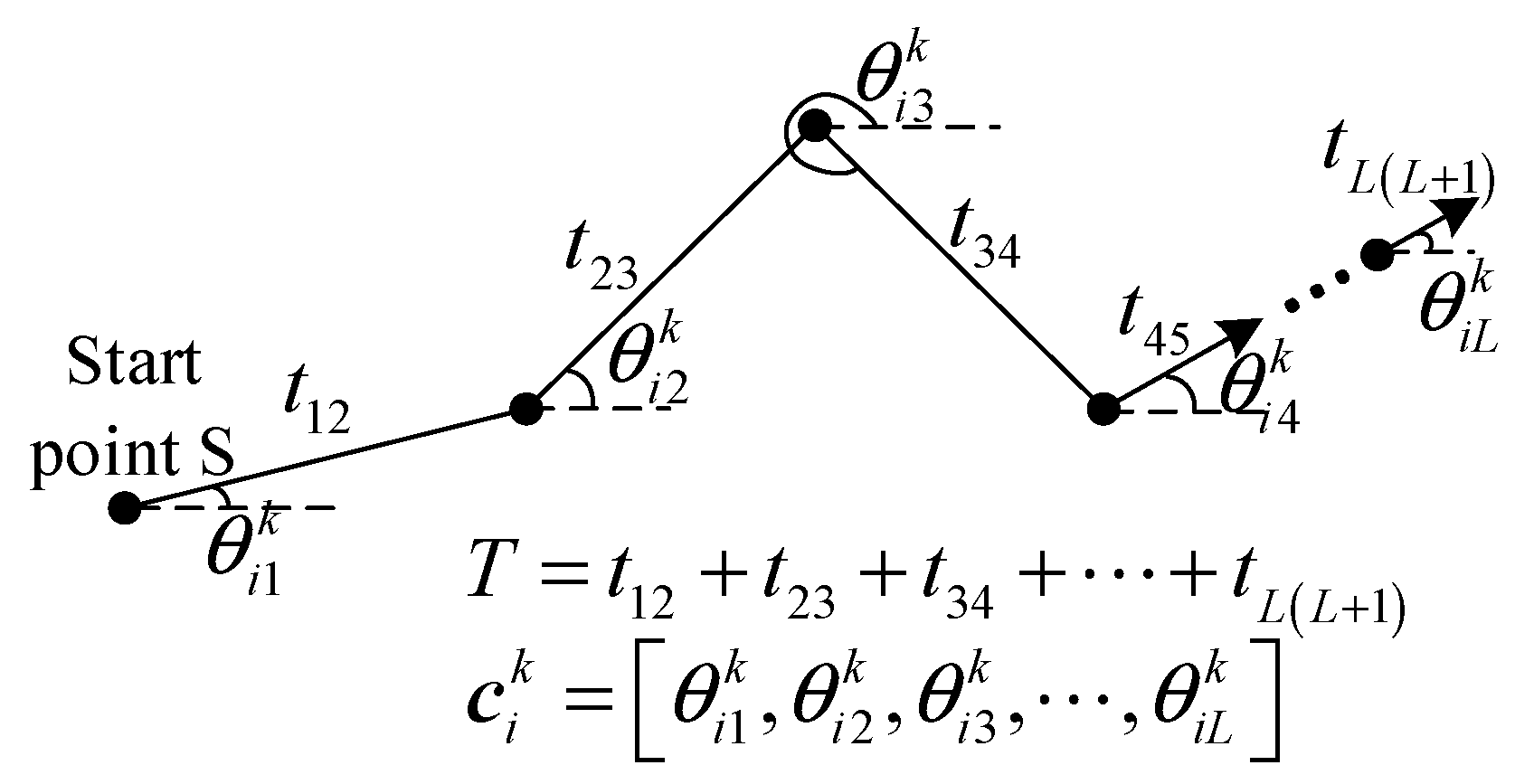
During target search operations, an AUV typically maintains a constant heading for a certain period (ranging from tens of seconds to several minutes) before adjusting its heading angle in response to environmental or mission conditions. When the AUV speed is constant, each interval of fixed heading can be defined as a segment. The representation of the search path is illustrated in Figure 3.
Where S represents the starting point of AUV. T represents the total length of the search period. t 12 , t 23 , …, t L L + 1 represent the length of each search period. L represents the number of search periods. c i k represents the path i . θ i j k represents the heading angle at the period j along path i .
A real number coding scheme is used to encode each path. The path population is the set of all search paths. The path population is denoted as follows:
C k = c 1 k , c 2 k , c i k , , c Q k           k = 1 , 2 , , K ,           i = 1 , 2 , , Q
where k represents the current population generation. K represents the maximum population generation. Q represents the size of the path population. c i k represents the path i in the population generation k .
c i k = θ i 1 k , θ i 2 k , θ i j k , , θ i L k           j = 1 , 2 , , L
where θ i j k represents the course in period j of the path i in the population generation k .
The initialization of the path population is based on the AUV’s initial position. To enhance the diversity of candidate paths, the initial position is taken as the starting point, and heading angles are randomly generated over the full 360° range. The duration of each path segment is determined according to the total search time, and an initial population of search paths is then constructed accordingly.

4.2. Path Selection and Intersection Strategy Based on Cumulative Detection Probability

Calculate the CDP of each path in the population. According to the definition of CDP, a path with a higher CDP indicates a greater likelihood of successfully detecting the target. Therefore, the population is ranked in descending order based on CDP values, and the top-ranked path is directly preserved in the next generation. The number of retained paths, denoted as A , is determined as follows:
A = P a Q
where P a is the probability of path selection.
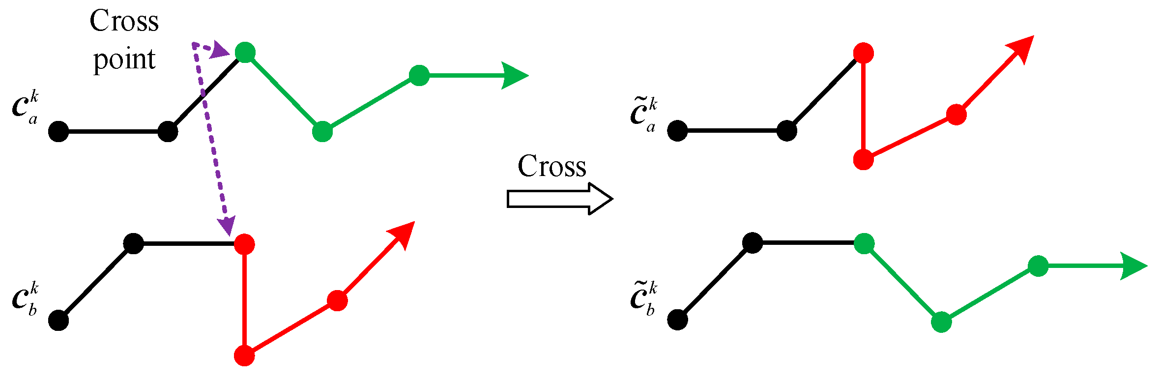
To enhance the diversity of candidate search paths, a crossover operation is applied to the population, with paths of higher CDP preferentially retained in the next generation. The crossover is performed probabilistically: two parent paths are selected based on their CDP values, and a new path is generated through single-point crossover. Paths with higher CDP have a greater likelihood of being selected. A schematic illustration of the crossover operation is presented in Figure 4.
Assume the crossover probability is P b . According to the selection method illustrated in Figure 4, two parent paths a and b are randomly selected based on their CDP values, and a random number R in [0, 1] is generated. When P b R , crossover is performed between paths a and b. Assuming that the crossover occurs at the period j , the two parent paths are recombined at this point to generate new offspring paths, as expressed in Equation (13).
c ˜ a k = θ a j k , θ b j + 1 k , c ˜ b k = θ b j k , θ a j + 1 k , P b R c a k = θ a j k , θ a j + 1 k , c b k = θ b j k , θ b j + 1 k , P b < R
where c a k and c b k are a group of randomly selected paths. R is a random number. The crossing operation selects B = P b Q as the number of individuals to be retained for the next generations.

4.3. Path Point Mutation Strategy Based on Target Position Control

To enhance the diversity of search path segments and ensure variability in AUV headings within the population, mutation operations are applied to the candidate paths. In the mutation process, both the direction and magnitude of mutation critically influence the search efficiency and convergence speed of the algorithm. In conventional genetic algorithms, mutation is typically implemented by randomly altering the heading angle of a path segment. However, this approach is independent of the target’s position distribution, leading to unguided mutation directions and low mutation efficiency.
In this paper, a mutation strategy guided by the target distribution is proposed based on the motion characteristics of targets and the properties of the search path population. Specifically, the mutation direction is determined by the relative orientation between the AUV and the grid-based target position distribution. Since the objective of the search is to maximize the probability of target detection, regions with higher target distribution probability are more likely to contain the target. Therefore, the target distribution map is used to guide the adjustment of the AUV heading during mutation, directing the evolution of the path population toward regions with higher detection likelihood.
Let the mutation probability be P c ; for each path in the population, a random number R in [0, 1] is generated. If R is less than the mutation probability, a mutation operation is applied to the selected path. Assuming that a mutation occurs on path a , the updated path can be expressed as follows:
c ˜ a k = θ a i k , , θ a j k , P c R c a k = θ a i k , , θ a j k ,   P c < R
where i and j are the two mutation periods randomly selected. R is a random number. θ a i k and θ a j k represent the heading angle in the two periods i and j after mutation. c ˜ a k is the path after mutation.
θ a i k = φ a k + d ( C max C min ) i = w T R 2 θ a j k = θ a j k + R 1 π ( k / K ) j = T w T R 2
where d is a random number within the interval [−0.5, 0.5]. R 1 is a random number within the interval [0.5, 1]. R 2 is a random number within the interval [0, 0.5]. C max and C min denote the maximum and minimum heading angles that follow normal distributions derived from the target’s prior information. The maximum and minimum heading angles, defined by the 3 σ range, are used to constrain the AUV’s search space to regions where the target is most likely to be located. w is the control parameter in the search period. φ a k represents the relative orientation between the grid center point with the maximum target position distribution probability and the AUV position when the mutation is performed on path a in period i , that is:
φ a k = arctan y max P i y a i k x max P i x a i k
where x max P i and y max P i represent the coordinates of the grid center point with the maximum target position distribution probability during period i . x a i k and y a i k represent the AUV position during period i on path a .
Equations (14)–(16) constitute the core of the proposed genetic algorithm with target-position-distribution-controlled mutation. Since the heading angle is the primary factor influencing the search path, variations in heading at different time steps lead to different path and, consequently, different search outcomes. In the early stage of the search, the AUV is directed toward regions with the highest target distribution probability, thereby increasing the likelihood of detection. In the later stage, as the target distribution becomes more dispersed, small-range mutations in the heading angle are insufficient. Therefore, the mutation amplitude is increased to enhance path diversity and expand the exploration of the search space. Accordingly, the proposed mutation strategy adopts a two-phase mechanism: in the initial phase, mutation is guided toward directions with high target probability to improve detection efficiency; in the subsequent phase, larger mutation amplitudes are introduced to diversify path points and enrich candidate solutions. Meanwhile, as the population converges in later iterations, excessive changes in heading should be avoided. Thus, the mutation amplitude is gradually reduced with the number of iterations to ensure stable convergence toward the optimal solution.
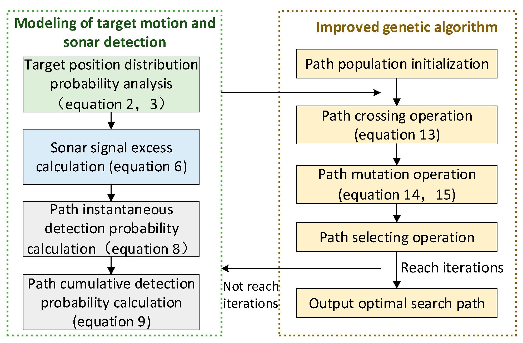
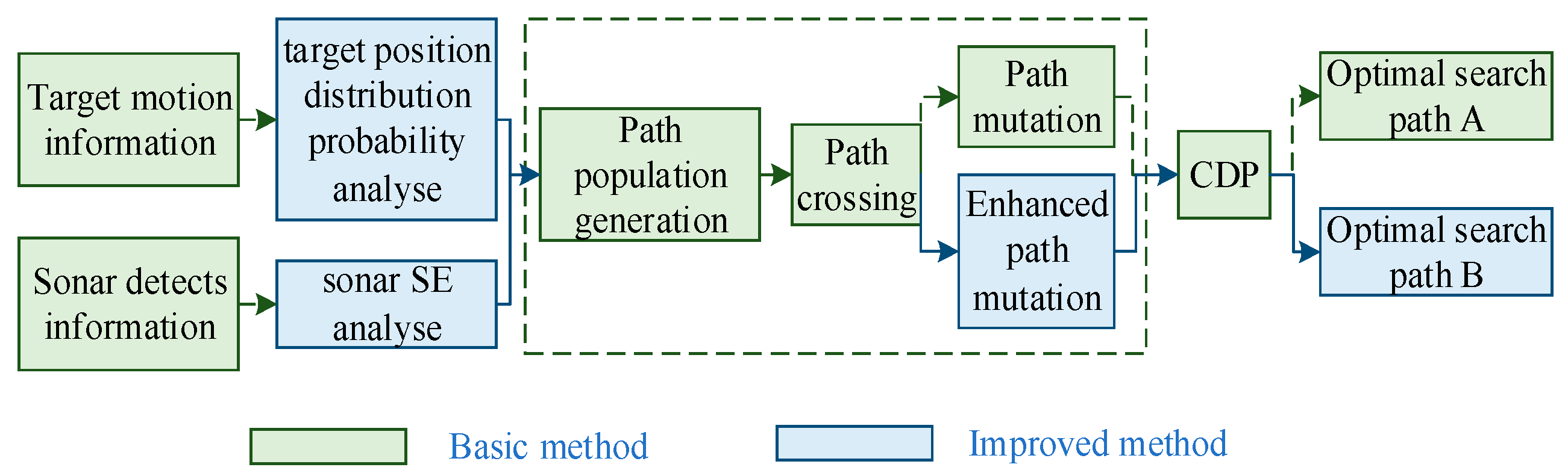
So far, the path planning for underwater moving target search based on target position control mutation factor genetic algorithm has been completed, and the principle is shown in Figure 5.

5. Simulated Analysis

5.1. Simulation Condition

To validate the proposed genetic algorithm for search path planning based on target-position-distribution-controlled mutation, simulation experiments were conducted. The simulation settings include prior information on the moving target, AUV motion capabilities, sonar detection performance, and genetic algorithm parameters. The detailed simulation conditions are listed in Table 1.
According to the target trajectory simulation method, the simulated heading angle and speed of the target follow a normal distribution. The initial position is m 0 . The target moves along the heading angle that follows a normal distribution with a mean value of θ and a standard deviation of σ θ . The speed of the target follows a normal distribution with a mean of V m and a standard deviation of σ v .
The structure of the simulation program is illustrated in Figure 6. The program consists of two main components. The first is a basic GA, which incorporates moving target information and sonar detection characteristics. The second is the proposed improved GA with a mutation strategy guided by target position distribution, which additionally includes probabilistic analysis of target location and a sonar detection model. The target cumulative detection probability (CDP) is employed as the performance metric to evaluate and compare the paths generated by the two methods.

5.2. Simulation of Moving Target Position Distribution Probability

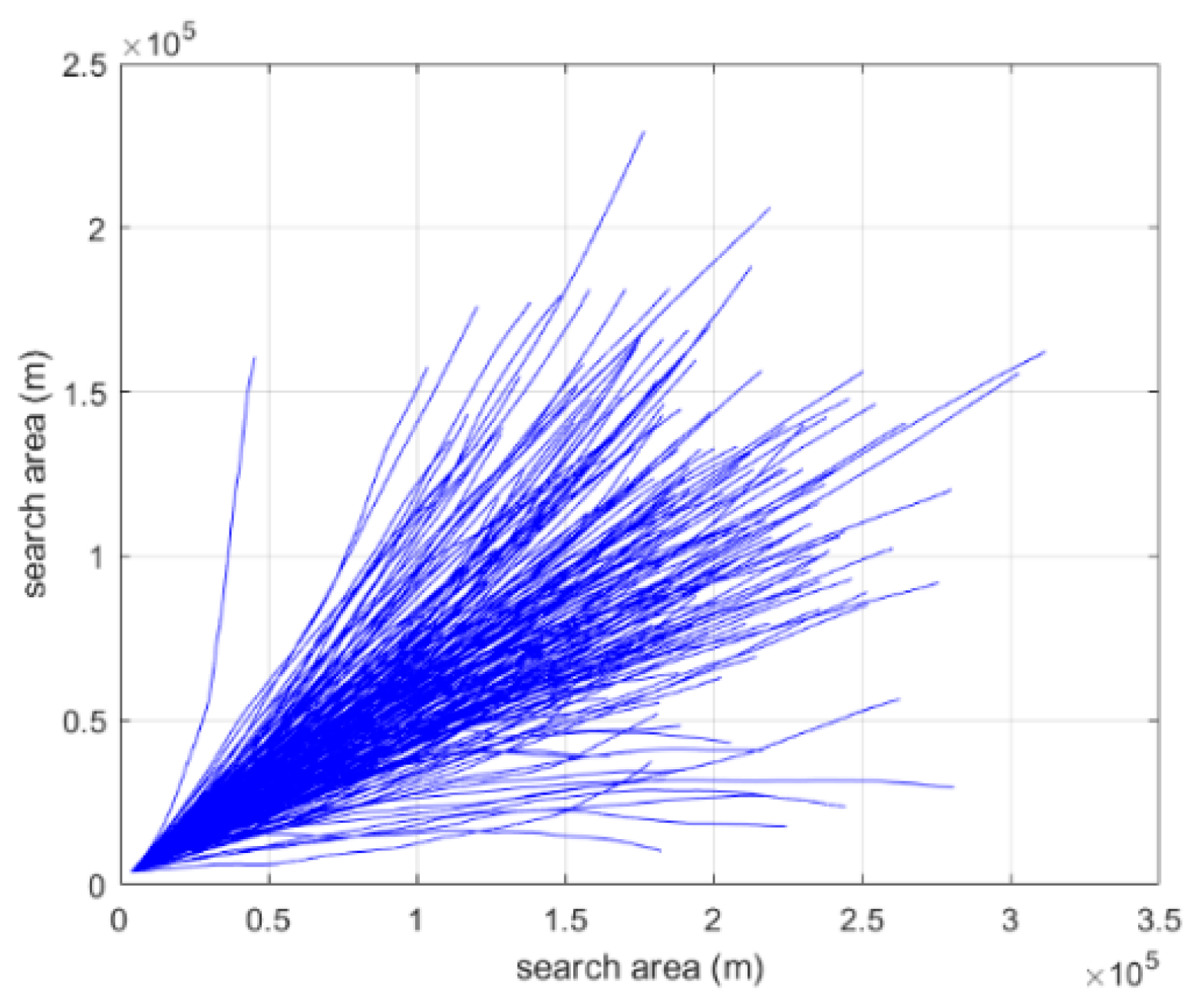
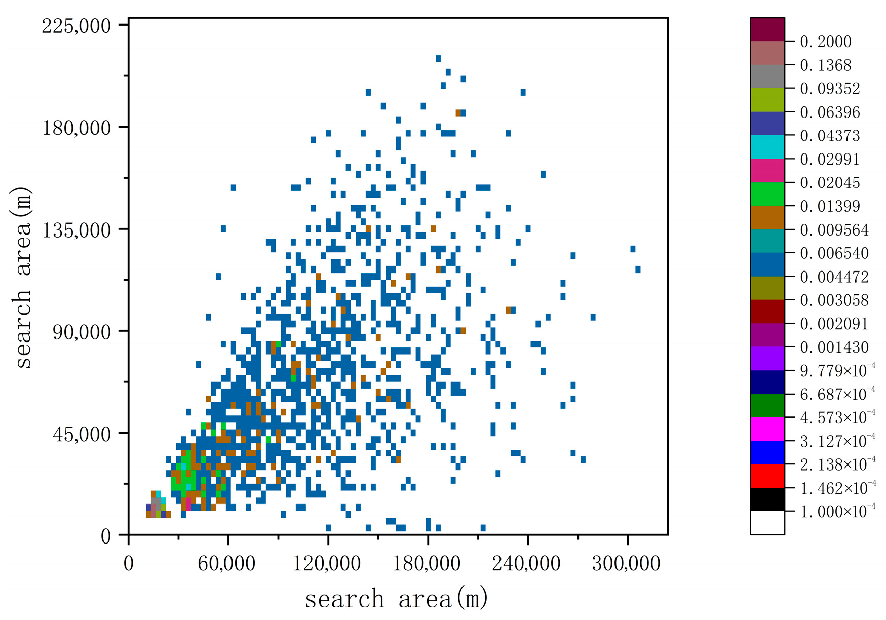
The target trajectory is simulated based on prior parameters, including the initial position, speed information, heading angle information, and total search duration. The search region (i.e., the potential target area) is discretized into grids, and the target position distribution probability within each grid cell is calculated at each time step. In this study, 200 target trajectories are generated. Each grid cell has dimensions of 3000 m × 3000 m, and the total simulation time is 8 h, corresponding to the overall search duration. The simulated target trajectories and the corresponding target position distributions are presented in Figure 7 and Figure 8, respectively. Figure 7 illustrates the 200 simulated target trajectories, while Figure 8 shows the pseudo-color map of the target position distribution probability after grid discretization, computed at hourly intervals starting from 0.5 h.
Figure 7 and Figure 8 correspond to the target motion trajectories and their discretized representation shown in Figure 1. Figure 8 illustrates the temporal evolution of the target position distribution probability, which directly informs the mutation strategy proposed in this study. As shown in the figure, the target distribution becomes increasingly dispersed over time. At 0.5 h, the maximum probability within a grid cell is approximately 0.3, the target distribution is relatively concentrated. By 7.5 h, the maximum probability decreases to about 0.02, the target distribution is dispersed. This phenomenon arises because the target heading angles, sampled from a normal distribution, generate trajectories that gradually diverge from the same initial position as time progresses. This temporal evolution implies that different mutation strategies should be adopted at different stages of the search. In the early stage, when the target distribution is concentrated, the search should be guided toward regions with higher probability, using directional mutation to steer the path population toward favorable areas. In the later stage, as the distribution becomes more dispersed, the mutation amplitude should be increased to enhance exploration and maximize the probability of target detection.
The grid size in Figure 8 is set to 3000 m × 3000 m based on the sonar detection characteristics considered in this study. According to the passive sonar equation and the sound source level specified in the simulation, the effective detection range is approximately 1500 m. Given the symmetry of sonar detection, the grid side length is chosen as twice the detection range to avoid missing potential targets due to overly coarse discretization. From a physical perspective, for a fixed search area, reducing the grid size increases the number of grid cells, causing the target probability to be distributed over more cells and thus decreasing the probability within each individual grid. However, smaller grids also reduce the effective detection distance within each cell, leading to higher SE values and, consequently, increased detection probability. As a result, the decrease in target distribution probability and the increase in detection probability offset each other to some extent, leading to CDP not being directly determined by grid size. Nevertheless, grid size significantly affects computational complexity. With fixed parameters such as population size, number of iterations, and path length, the computational cost is proportional to the total number of grid cells N × M. A larger number of grids leads to higher computational burden. Conversely, excessively large grids concentrate probability into fewer cells, which may cause missed detections and degrade algorithm performance. Therefore, selecting the grid size based on the sonar detection range provides a reasonable balance between accuracy and computational efficiency.

5.3. Simulation of Sonar Detection Signal Excess

By taking the intersection of each grid’s diagonal lines as the center point, the sonar detection direction is set at an azimuth of 90° relative to the center. Eight radial directions around the center are then selected, and the corresponding sonar SE is calculated at discrete intervals along each direction. The results are presented in Figure 9. The left panel shows the spatial distribution of SE across all grid cells, while the right panel provides a magnified view of SE within a single grid. The color scale represents the magnitude of SE, with values increasing as the color approaches yellow.
As shown in the figure, due to the influence of the sonar directivity coefficient, even when the target–sonar distance is identical, the SE is higher in the principal detection direction (approximately 85–105° in the figure) than in other directions. This indicates that targets located within the main lobe of the sonar beam are more likely to be detected. When the target and the AUV are located within the same grid cell, the SE value can be determined based on their relative position and the distance to the grid center. If the SE value is greater than zero, the corresponding instantaneous detection probability and cumulative detection probability are then computed accordingly.

5.4. Implementation and Analysis of Search Path Planning Algorithm

5.4.1. Effectiveness Validation of the Proposed Genetic Algorithm for Search Path Planning

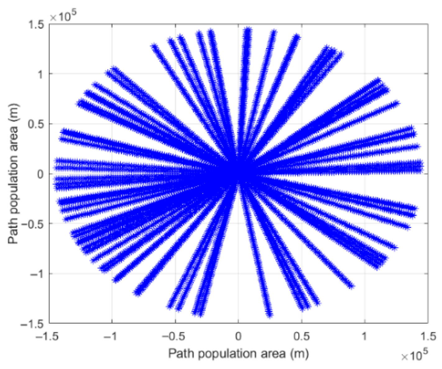
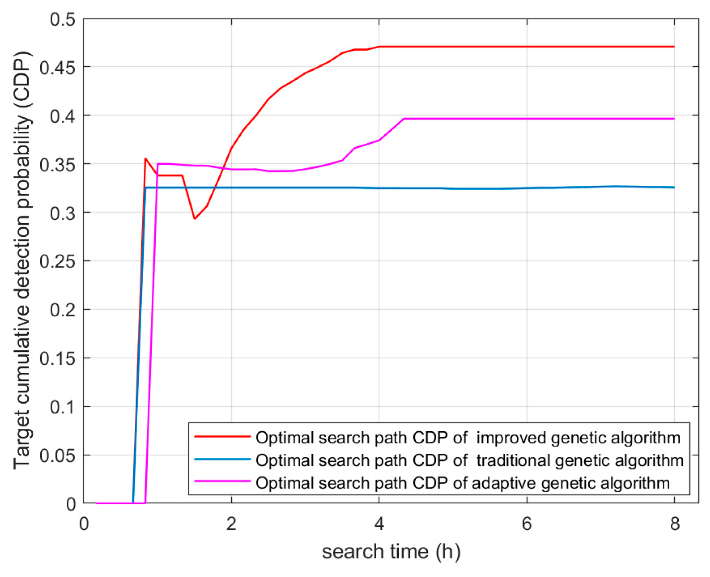
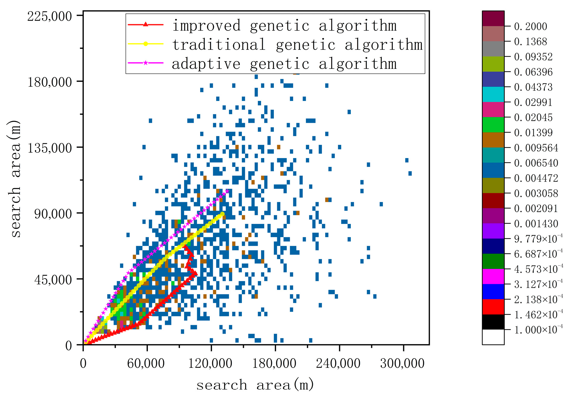
The initial population of search paths is illustrated in Figure 10. After 20 independent runs, the optimal search path obtained using the proposed genetic algorithm with the improved mutation strategy is shown in Figure 11. For comparison, paths generated by the conventional genetic algorithm and the adaptive genetic algorithm [49] are included as control groups. The corresponding target cumulative detection probability curves are also presented in Figure 11, where the horizontal axis represents search time and the vertical axis denotes the target cumulative detection probability value. Figure 12 depicts the relationship between the optimal search paths and the target for the three algorithms. The red curve denotes the optimal path obtained by the proposed method, the yellow curve corresponds to the conventional genetic algorithm, and the pink curve represents the adaptive genetic algorithm.
Figure 11 and Figure 12 demonstrate that the search path generated by the proposed algorithm effectively covers regions where the target is likely to be present. Combined with the target position distribution probability shown in Figure 9, it can be observed that the optimal path in Figure 12 traverses grid cells with high target existence probability. The AUV first detects the target at approximately 0.8 h after the start of the search, at which point the CDP increases rapidly. Following this, the CDP exhibits a slight decrease and then gradually recovers, indicating a temporary deviation of the search path from regions with higher target probability. After subsequent adjustment by the algorithm, the path returns to high-probability areas, and the CDP continues to increase, eventually stabilizing at 0.48. This result confirms that the proposed method can effectively improve target search performance.
To evaluate the effectiveness of the proposed mutation strategy, the improved genetic algorithm is compared with both the traditional genetic algorithm and the adaptive genetic algorithm. The CDP curves corresponding to the optimal search paths of the three methods are presented in Figure 11. As shown, the optimal CDP achieved by the proposed method is 0.48, compared with 0.38 for the adaptive genetic algorithm and 0.33 for the traditional genetic algorithm. This represents an improvement of 0.15 over the conventional approach and 0.10 over the adaptive variant. Moreover, in the proposed algorithm, the CDP continues to increase even after the AUV first detects the target, indicating that the AUV maintains effective search capability in subsequent stages. This result demonstrates that the improved mutation strategy significantly enhances search performance.

5.4.2. Impact of AUV Initial Position on the Performance of the GA with Improved Mutation Strategy

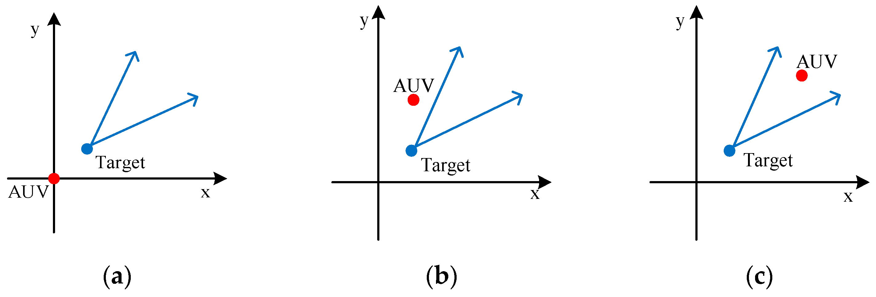
When the target’s initial position is fixed, variations in the AUV’s initial position lead to differences in relative orientation, distance, and relative motion between the AUV and the target, thereby affecting search efficiency. Therefore, under identical prior information for the target, this study analyzes the impact of three different AUV initial positions on search performance. The geometric relationships between the three AUV initial positions and the target are illustrated in Figure 13. In the figure, the red point denotes the AUV’s initial position, the blue point represents the target’s initial position, and the blue arrow indicates the target’s heading range. The three AUV initial positions are set to (0 km, 0 km), (4 km, 12 km), and (80 km, 80 km), respectively.
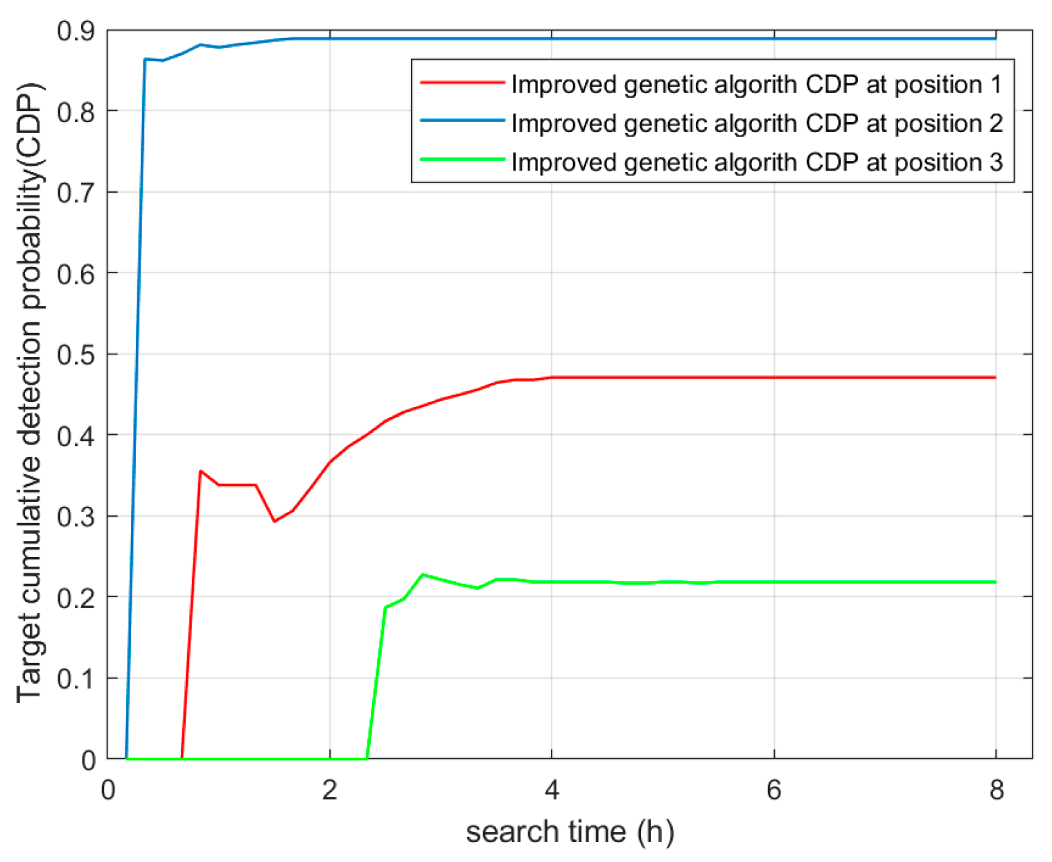
Under the three initial position configurations, the optimal search path CDP obtained using the proposed genetic algorithm with the improved mutation strategy is shown in Figure 14. When the AUV starts from Position 2, the generated path enters regions with high target existence probability at approximately 0.3 h, resulting in an increase in CDP. As time progresses and the target distribution becomes more dispersed, the growth rate of CDP gradually decreases, eventually stabilizing at 0.88. In this case, the initial distance between the AUV and the target is relatively small, and the relative speed difference is favorable, enabling the search path to effectively cover high-probability regions, leading to the highest CDP. When the AUV starts from Position 1, the path enters high-probability regions at around 0.8 h, at which point the CDP begins to increase. However, due to the larger initial separation between the AUV and the target, the target distribution is already more dispersed when first detected, resulting in lower coverage efficiency compared to Position 2. Consequently, the final CDP reaches 0.48. When the AUV starts from Position 3, the initial distance to the target is significantly larger. The AUV fails to detect the target until approximately 2.5 h after the search begins, by which time the target distribution has become highly dispersed (with a maximum probability of about 0.02). Although subsequent paths partially cover the target region, the final CDP only reaches 0.22.
In summary, the proposed genetic algorithm guides mutation directions using the target position distribution probability, enabling search paths from different initial positions to preferentially cover regions with higher target existence probability. Comparing the results for Positions 1 and 2 indicates that the initial distance between the AUV and the target directly affects the time required for the AUV to enter high-probability regions. The results for Position 3 further demonstrate that even when the initial distance is large, the algorithm can still achieve limited search effectiveness if the AUV and target exhibit favorable relative motion. It should be noted that appropriate boundary conditions must be considered when setting AUV motion parameters. For example, at Position 1, if the AUV speed is too low or the initial distance is too large, the AUV may fail to reach high-probability regions before the target distribution becomes highly dispersed, leading to search failure. These findings provide practical guidance for AUV deployment in real-world applications.

5.4.3. Stability Analysis of Improved Mutation Strategy Genetic Algorithm

To evaluate the stability of the proposed genetic algorithm with the improved mutation strategy, five independent simulation experiments were conducted. The CDP values of the optimal paths obtained from these runs are summarized in Table 2. As shown, under identical simulation conditions, the mean CDP of the optimal search paths is 0.4528, with a variance of 0.0008. These results indicate that the proposed method exhibits strong stability and consistent performance, demonstrating its potential as a reliable approach for AUV target search applications.
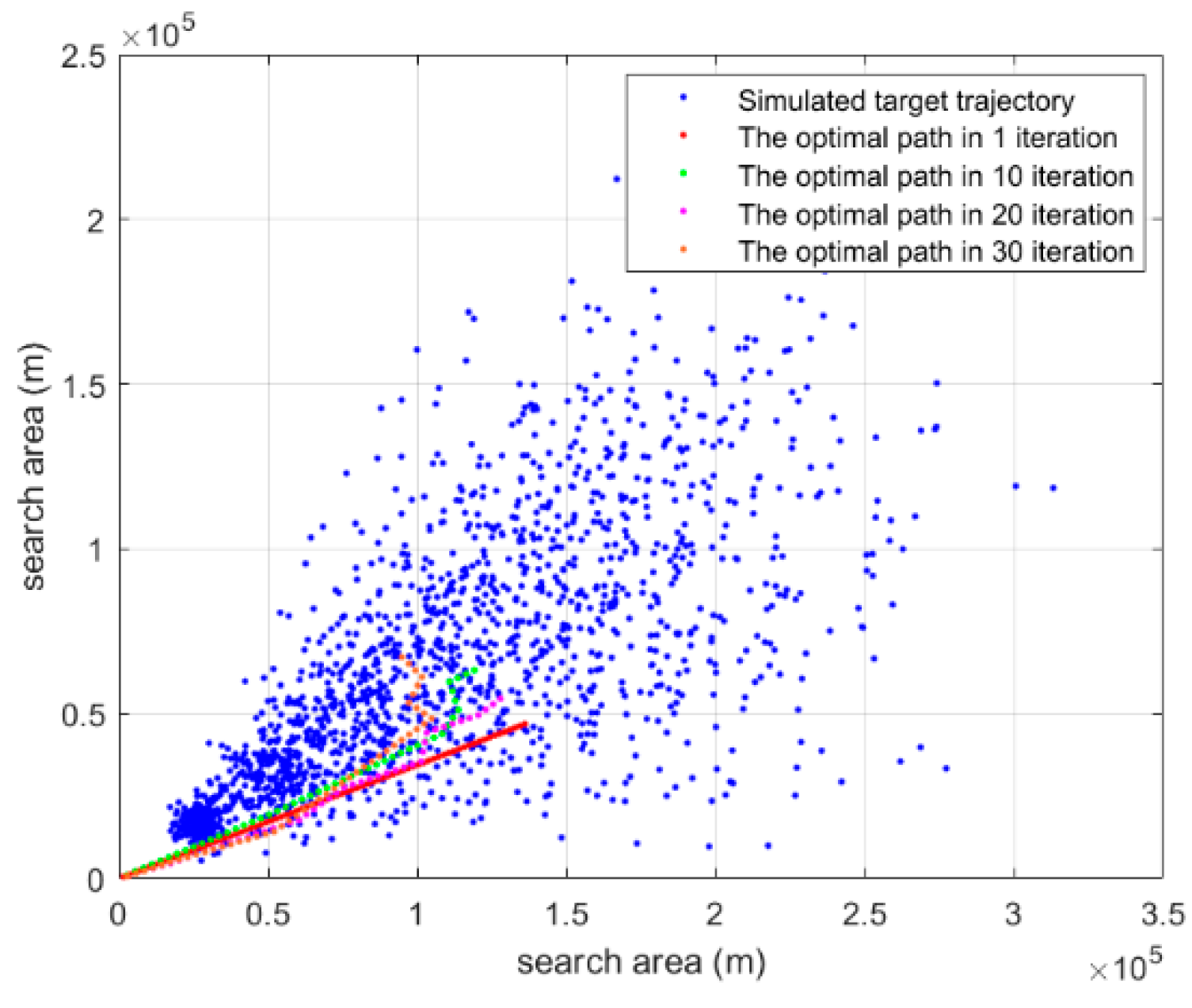
Figure 15 shows the optimal path for different iterations of the improved genetic algorithm. The optimal path for iterations of 1, 10, 20, and 30 times respectively.
As shown in the figure, the optimal path consistently evolves toward regions with the highest concentration of target points. As the number of iterations increases, the path progressively converges to areas with the greatest target density. This indicates that the proposed method effectively guides the search path toward regions with the highest target position distribution probability.

6. Conclusions

This paper proposes a genetic algorithm-based path planning method for underwater moving target search. First, to address the uncertainty of target motion, a Markov process combined with a grid-based approach is employed to model target dynamics and estimate the distribution probability of target positions. Second, based on the target distribution grid, a sonar detection probability model is developed by incorporating the effects of random fluctuations in the sonar signal excess. Finally, the target position distribution probability and sonar detection probability model are integrated into the genetic algorithm, and the mutation strategy is improved according to the characteristics of the search path to obtain an optimal AUV search trajectory. Simulation results demonstrate that, compared with the traditional genetic algorithm and the adaptive genetic algorithm, the proposed method increases the target cumulative detection probability by 0.15 and 0.10, respectively. These results confirm that the method can effectively plan AUV search paths under conditions of stochastic target motion and random fluctuations in sonar signal excess. However, the influence of time-varying sonar characteristics on path planning has not been considered in this study and will be investigated in future work.

Author Contributions

Investigation, Q.W.; Software, S.Z.; Writing—original draft, Q.W. and S.Z.; Visualization, Y.H.; Supervision, Q.W.; Funding acquisition, Q.W. All authors have read and agreed to the published version of the manuscript.

Funding

This work was supported by the National Key R&D Program of China (2023YFC2808500).

Data Availability Statement

The original contributions presented in this study are included in the article. Further inquiries can be directed to the corresponding author.

Conflicts of Interest

The authors declare no conflicts of interest.

Abbreviations

The following abbreviations are used in this manuscript:
AUVAutonomous underwater vehicle
GAGenetic algorithm
CDPcumulative detection probability
SEsignal excess

References

  1. Zhang, J.; Han, G.; Sha, J.; Qian, Y.; Liu, J. AUV-assisted subsea exploration method in 6G enabled deep ocean based on a cooperative pac-men mechanism. IEEE Trans. Intell. Transp. Syst. 2021, 23, 1649–1660. [Google Scholar] [CrossRef] [Scilit]
  2. Ahn, J.; Yasukawa, S.; Sonoda, T.; Nishida, Y.; Ishii, K.; Ura, T. An optical image transmission system for deep sea creature sampling missions using autonomous underwater vehicle. IEEE J. Ocean. Eng. 2018, 45, 350–361. [Google Scholar] [CrossRef] [Scilit]
  3. Topini, A.; Topini, E.; Ridolfi, A. Multi-hypothesis task planning: Integrating temporal ai planning and semantic world modeling for AUV inspections in unknown environments. In Proceedings of the OCEANS 2023, Limerick, Ireland, 5–8 June 2023; pp. 1–10. [Google Scholar] [CrossRef] [Scilit]
  4. Cashmore, M.; Fox, M.; Larkworthy, T.; Long, D.; Magazzeni, D. AUV mission control via temporal planning. In Proceedings of the 2014 IEEE ICRA, Hong Kong, China, 31 May–7 June 2014; pp. 6535–6541. [Google Scholar] [CrossRef] [Scilit]
  5. Zhou, N.; Zhu, Z.; Mu, X.; Zhou, L.; Qin, H.; Bai, G. Hybrid-Algorithm-Based Emergency Search and Rescue Method With AUV to Uncertain Environment in Internet of Underwater Things. IEEE Internet Things J. 2025, 12, 29925–29939. [Google Scholar] [CrossRef] [Scilit]
  6. Cui, R.; Li, Y.; Yan, W. Mutual information-based multi-AUV path planning for scalar field sampling using multidimensional RRT. IEEE. Trans. Syst. Man. Cybern. 2015, 46, 993–1004. [Google Scholar] [CrossRef] [Scilit]
  7. Cao, X.; Ren, L.; Sun, C. Dynamic target tracking control of autonomous underwater vehicle based on trajectory prediction. IEEE. Trans. Cybern. 2022, 53, 1968–1981. [Google Scholar] [CrossRef] [Scilit]
  8. Wang, Y.; Ma, X.; Wang, J.; Hou, S.; Dai, J.; Gu, D.; Wang, H. Robust AUV visual loop-closure detection based on variational autoencoder network. IEEE. Trans. Ind. Inf. 2022, 18, 8829–8838. [Google Scholar] [CrossRef] [Scilit]
  9. De Carolis, V.; Brown, K.E.; Lane, D.M. Runtime energy estimation and route optimization for autonomous underwater vehicles. IEEE J. Ocean. Eng. 2017, 43, 608–619. [Google Scholar] [CrossRef] [Scilit]
  10. Zhu, D.; Zhou, B.; Yang, S.X. A novel algorithm of multi-AUVs task assignment and path planning based on biologically inspired neural network map. IEEE. Intell. Veh. 2020, 6, 333–342. [Google Scholar] [CrossRef] [Scilit]
  11. Yao, P.; Zhao, Z.; Zhu, Q. Path planning for autonomous underwater vehicles with simultaneous arrival in ocean environment. IEEE. Syst. J. 2019, 14, 3185–3193. [Google Scholar] [CrossRef] [Scilit]
  12. Yu, X.; Chen, W.-N.; Hu, X.-M.; Gu, T.; Yuan, H.; Zhou, Y.; Zhang, J. Path planning in multiple-AUV systems for difficult target traveling missions: A hybrid metaheuristic approach. IEEE. Trans. Dev. Syst. 2019, 12, 561–574. [Google Scholar] [CrossRef] [Scilit]
  13. Li, L.; Li, Y.; Wang, Y.; Xu, G.; Wang, H.; Gao, P.; Feng, X. Multi-AUV coverage path planning algorithm using side-scan sonar for maritime search. Ocean Eng. 2024, 300, 20. [Google Scholar] [CrossRef] [Scilit]
  14. Cao, X.; Zhu, D.; Yang, S.X. Multi-AUV target search based on bioinspired neurodynamics model in 3-D underwater environments. IEEE. Trans. Neural Netw. Learn. Syst. 2015, 27, 2364–2374. [Google Scholar] [CrossRef] [Scilit]
  15. Eagle, J.N.; Yee, J.R. An optimal branch-and-bound procedure for the constrained path, moving target search problem. Oper. Res. 1990, 38, 110–114. [Google Scholar] [CrossRef] [Scilit]
  16. Khatib, O. Real-time obstacle avoidance for manipulators and mobile robots. Int. J. Robot. Res. 1986, 5, 90–98. [Google Scholar] [CrossRef] [Scilit]
  17. Lai, Y.; Li, Y.; Xu, Z.; Han, J.; Kang, W.; Liu, Z. A Review on Path Planning for Autonomous Underwater Vehicles: From Models, Classical Methods, and Learning-Based Intelligence Perspectives. J. Field Robot. 2025, 43, 2366–2389. [Google Scholar] [CrossRef] [Scilit]
  18. Cheng, C.-T.; Fallahi, K.; Leung, H.; Tse, C.K. A genetic algorithm-inspired UUV path planner based on dynamic programming. IEEE. Trans. Syst. Man. Cybern. C. 2012, 42, 1128–1134. [Google Scholar] [CrossRef] [Scilit]
  19. Wen, J.; Yang, J.; Wang, T. Path planning for autonomous underwater vehicles under the influence of ocean currents based on a fusion heuristic algorithm. IEEE. Trans. Veh. Technol. 2021, 70, 8529–8544. [Google Scholar] [CrossRef] [Scilit]
  20. Petres, C.; Pailhas, Y.; Patron, P.; Petillot, Y.; Evans, J.; Lane, D. Path planning for autonomous underwater vehicles. IEEE. Trans. Robot. 2007, 23, 331–341. [Google Scholar] [CrossRef] [Scilit]
  21. Li, Y.; Zhu, D. Formation tracking and transformation of AUVs based on the improved particle swarm optimization algorithm. In Proceedings of the 2020 Chinese Control And Decision Conference (CCDC), Hefei, China, 22–24 August 2020; pp. 3159–3462. [Google Scholar] [CrossRef] [Scilit]
  22. Li, L.; Gu, Q.; Liu, L. Research on path planning algorithm for multi-UAV maritime targets search based on genetic algorithm. In Proceedings of the 2020 IEEE International Conference on Information Technology, Big Data and Artificial Intelligence (ICIBA), Chongqing, China, 6–8 November 2020; pp. 840–843. [Google Scholar] [CrossRef] [Scilit]
  23. Cao, X.; Chen, L.; Guo, L.; Han, W. AUV Global Security Path Planning Based on a Potential Field Bio-Inspired Neural Network in Underwater Environment. Intell. Autom. Soft Comput. 2021, 27, 390–407. [Google Scholar] [CrossRef] [Scilit]
  24. Liu, Q.; Shi, L.; Sun, L.; Li, J.; Ding, M.; Shu, F.S. Path planning for UAV-mounted mobile edge computing with deep reinforcement learning. IEEE. Trans. Veh. Technol. 2020, 69, 5723–5728. [Google Scholar] [CrossRef] [Scilit]
  25. Kermani, P.; Afzalian, A.A. Flight path planning using GA and fuzzy logic considering communication constraints. In Proceedings of the 7’th International Symposium on Telecommunications (IST’2014), Tehran, Iran, 9–11 September 2014; pp. 6–11. [Google Scholar] [CrossRef] [Scilit]
  26. Deb, K.; Pratap, A.; Agarwal, S.; Meyarivan, T. A fast and elitist multiobjective genetic algorithm: NSGA-II. IEEE. Evol. Comput. 2002, 6, 182–197. [Google Scholar] [CrossRef] [Scilit]
  27. Guo, Y.; Liu, H.; Fan, X.; Lyu, W. Research progress of path planning methods for autonomous underwater vehicle. Math. Probl. Eng. 2021, 2021, 8847863. [Google Scholar] [CrossRef] [Scilit]
  28. Zeng, Z.; Sammut, K.; Lian, L.; He, F.; Lammas, A.; Tang, Y. A comparison of optimization techniques for AUV path planning in environments with ocean currents. Robot. Auton. Syst. 2016, 82, 61–72. [Google Scholar] [CrossRef] [Scilit]
  29. Tanakitkorn, K.; Wilson, P.A.; Turnock, S.R.; Phillips, A.B. Grid-based GA path planning with improved cost function for an over-actuated hover-capable AUV. In Proceedings of the 2014 IEEE/OES Autonomous Underwater Vehicles (AUV), Oxford, MS, USA, 6–9 October 2014; pp. 1–8. [Google Scholar] [CrossRef] [Scilit]
  30. Yan, Z.; He, J.; Li, J. An improved multi-AUV patrol path planning method. In Proceedings of the 2017 IEEE International Conference on Mechatronics and Automation (ICMA), Takamatsu, Japan, 6–9 August 2017; pp. 1930–1936. [Google Scholar] [CrossRef] [Scilit]
  31. Wang, Y.; Li, W.; Jiang, R. A novel hybrid algorithm based on improved particle swarm optimization algorithm and genetic algorithm for multi-UAV path planning with time windows. In Proceedings of the 2022 IEEE 5th Advanced Information Management, Communicates, Electronic and Automation Control Conference (IMCEC), Chongqing, China, 16–18 December 2022; pp. 1005–1009. [Google Scholar]
  32. Germi, S.B.; Khosravi, M.A.; FesharakiFard, R. Adaptive GA-based potential field algorithm for collision-free path planning of mobile robots in dynamic environments. In Proceedings of the 2018 6th RSI International Conference on Robotics and Mechatronics (IcRoM), Tehran, Iran, 23–25 October 2018; pp. 28–33. [Google Scholar] [CrossRef] [Scilit]
  33. Zhang, Q.R. A hierarchical global path planning approach for AUV based on genetic algorithm. In Proceedings of the 2006 International Conference on Mechatronics and Automation, Luyang, China, 25–28 June 2006; pp. 1745–1750. [Google Scholar] [CrossRef] [Scilit]
  34. Cho, J.H.; Kim, J.S. Measure of effectiveness analysis of passive sonar system for detection. Diabetes Care 2012, 15, 272–287. [Google Scholar] [CrossRef] [Scilit]
  35. Kierstead, D.P.; DelBalzo, D.R. A genetic algorithm applied to planning search paths in complicated environments. Mil. Oper. Res. 2003, 8, 45–59. [Google Scholar] [CrossRef] [Scilit]
  36. Sahoo, S.P.; Das, B.; Pati, B.B.; Marquez, F.P.G.; Ramirez, I.S. Hybrid path planning using a bionic-inspired optimization algorithm for autonomous underwater vehicles. J. Mar. Sci. Eng. 2023, 11, 761. [Google Scholar] [CrossRef] [Scilit]
  37. Lu, N.; Gong, Y.; Pan, J. Path planning of mobile robot with path rule mining based on GA. In Proceedings of the 2016 Chinese Control and Decision Conference (CCDC), Yinchuan, China, 28–30 May 2016; pp. 1600–1604. [Google Scholar] [CrossRef] [Scilit]
  38. Pan, F. Research on path planning of AUV based on improved genetic algorithms. In Proceedings of the 2021 International Conference on Computer, Control and Robotics (ICCCR), Shanghai, China, 8–10 January 2021; pp. 26–29. [Google Scholar] [CrossRef] [Scilit]
  39. Roberge, V.; Tarbouchi, M.; Labonté, G. Comparison of parallel genetic algorithm and particle swarm optimization for real-time UAV path planning. IEEE. Ind. Inf. 2013, 9, 132–141. [Google Scholar] [CrossRef] [Scilit]
  40. Song, Y.; He, B.; Liu, P. Real-time object detection for AUVs using self-cascaded convolutional neural networks. IEEE. J. Ocean. Eng. 2021, 46, 56–67. [Google Scholar] [CrossRef] [Scilit]
  41. Bays, M.J.; Redfield, S.A. Towards tracking a row of discrete targets with AUVs using Markov Decision Processes and probabilistic techniques. In Proceedings of the 2008 IEEE/OES Autonomous Underwater Vehicles, Woods Hole, MA, USA, 13–14 October 2008; pp. 1–6. [Google Scholar] [CrossRef] [Scilit]
  42. Caiti, A.; Martini, D.; Morellato, V.; Vettori, G. A Monte Carlo simulator for evaluation of AUV configuration in object search and classification missions. In Proceedings of the Europe Oceans 2005, Brest, France, 20–23 June 2005; pp. 1024–1027. [Google Scholar] [CrossRef] [Scilit]
  43. Baxendale, P.H.; Lototsky, S.V. Stochastic Differential Equations: Theory and Applications; World Scientific: Hackensack, NJ, USA, 2007; pp. 15–64. [Google Scholar]
  44. Li, J.H.; Park, D.G.; Ki, H.S. Sonar image processing based underwater localization and path planning for AUV’s autonomous swimming. In Proceedings of the 2018 5th International Conference on Control, Decision and Information Technologies (CoDIT), Thessaloniki, Greece, 10–13 April 2018; pp. 611–615. [Google Scholar] [CrossRef] [Scilit]
  45. Liu, C.; Liu, R.; Gao, F. Real-time AUV path planning algorithm in complex marine environment. In Proceedings of the 2021 IEEE International Conference on Unmanned Systems (ICUS), Beijing, China, 15–17 October 2021; pp. 110–115. [Google Scholar] [CrossRef] [Scilit]
  46. Guo, H.; Mao, Z.; Ding, W.; Liu, P. Optimal search path planning for unmanned surface vehicle based on an improved genetic algorithm. Comput. Electr. Eng. 2019, 79, 56–67. [Google Scholar] [CrossRef] [Scilit]
  47. Cho, J.-H.; Kim, J.-S.; Lim, J.-S.; Kim, S.; Kim, Y.-S. Optimal acoustic search path planning in realistic environments based on genetic algorithm. In Proceedings of the OCEANS 2008—MTS/IEEE Kobe Techno-Ocean, Kobe, Japan, 8–11 April 2008; pp. 1–8. [Google Scholar] [CrossRef] [Scilit]
  48. Mizuno, K.; Saito, Y.; Katase, F.; Nagahashi, K.; Asada, A. Development of the parametric sub-bottom profiler for autonomous underwater vehicles—Prediction of the reflection level using sonar equation based on TBE and Biot-Stoll model. In Proceedings of the 2017 IEEE Underwater Technology (UT), Busan, Republic of Korea, 21–24 February 2017; pp. 1–4. [Google Scholar] [CrossRef] [Scilit]
  49. Hao, K.; Zhao, J.; Li, Z.; Liu, Y.; Zhao, L. Dynamic path planning of a three-dimensional underwater AUV based on an adaptive genetic algorithm. Ocean Eng. 2022, 263, 112421. [Google Scholar] [CrossRef] [Scilit]
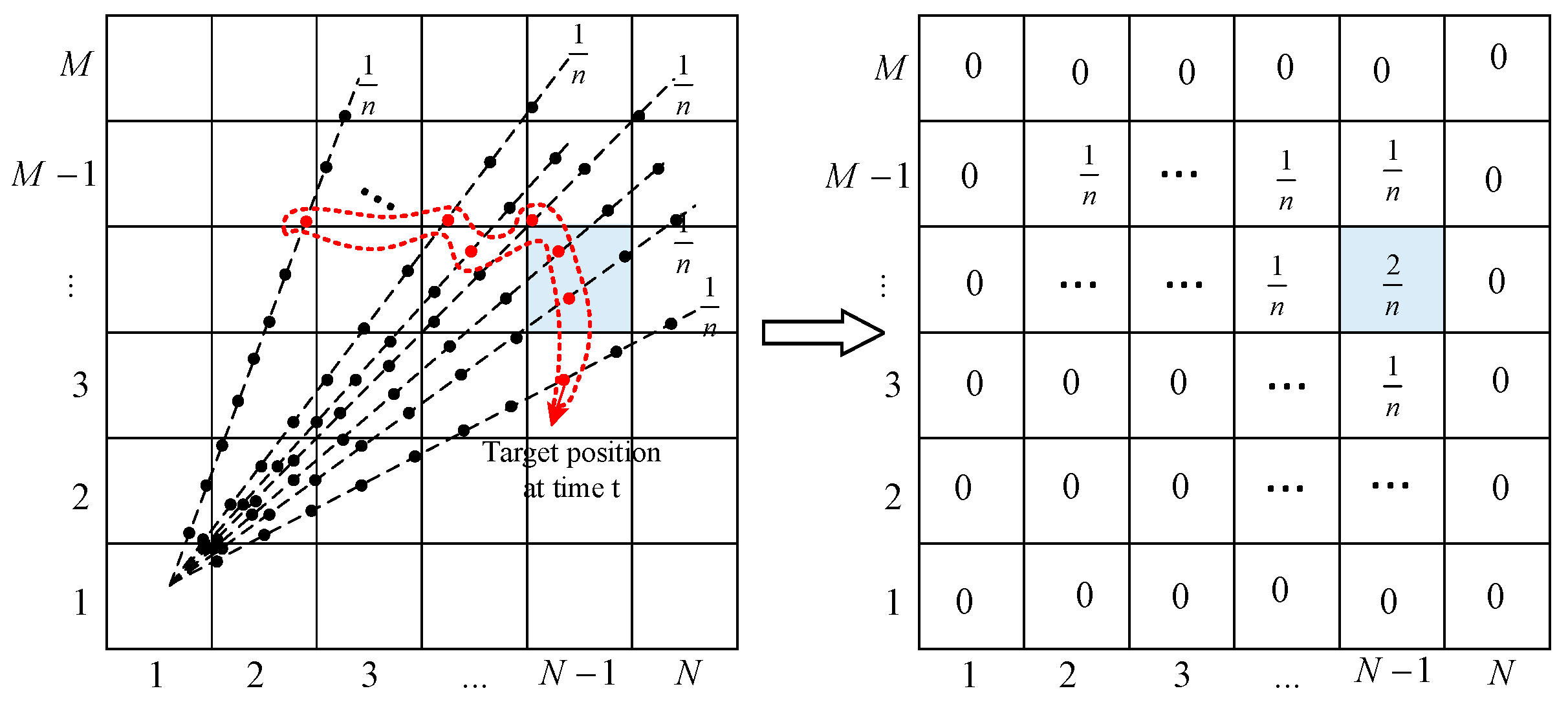
Figure 1. Schematic diagram of target motion area discretization based on the grid method.
Jmse 14 00805 g001
Figure 2. Schematic of 8 radial sonar signal excess values.
Jmse 14 00805 g002
Figure 3. Description of the search path.
Jmse 14 00805 g003
Figure 4. Schematic diagram of path crossing operation.
Jmse 14 00805 g004
Figure 5. Block diagram of search path planning based on improved genetic algorithm.
Jmse 14 00805 g005
Figure 6. Schematic diagram of simulation program structure.
Jmse 14 00805 g006
Figure 7. Simulated target trajectory.
Jmse 14 00805 g007
Figure 8. Target position distribution probability.
Jmse 14 00805 g008
Figure 9. Sonar detection signal excess in the search area.
Jmse 14 00805 g009
Figure 10. Initial population of search path.
Jmse 14 00805 g010
Figure 11. Target cumulative detection probability of the optimal search path.
Jmse 14 00805 g011
Figure 12. Optimal search path with target position distribution.
Jmse 14 00805 g012
Figure 13. Schematic diagram of the relationship between AUV and target initial position. (a) Position 1; (b) Position 2; (c) Position 3.
Jmse 14 00805 g013
Figure 14. Optimal path CDP of the improved genetic algorithm under three AUV initial positions.
Jmse 14 00805 g014
Figure 15. Optimal search path for different iterations.
Jmse 14 00805 g015
Table 1. Title simulation conditions.
NumInput ParameterSet Value
1Motion
target
Initial position m 0 (4 km, 4 km)
2Speed mean V m 7 m/s
3Speed standard deviation σ v 0.667
4Heading angle means θ 30°
5Heading angle standard deviation σ θ 6.67
6Process noise variance q 0.005
7Total time T 8 h
8AUV parameterSpeed5 m/s
9Initial position S (0 km, 0 km)
10Search total time T 8 h
11Sonar parameterSound source level SL85 dB
12Noise grade NL10 dB
13Threshold detection DT10 dB
14Genetic algorithm
parameter
Maximum number of iterations K 30
15Population size Q 40
16Period length0.5 h
17Selective probability P a 0.2
18Crossover probability P b 0.5
19Mutation probability P c 0.3
20Control parameter in the search period w 0.5
Table 2. Cumulative detection probability of optimal search path obtained by 5 simulation experiments.
NumCDP Maximum ValueCDP Mean ValueCDP Variance
10.4320.45280.0008
20.444
30.493
40.480
50.415
Disclaimer/Publisher’s Note: The statements, opinions and data contained in all publications are solely those of the individual author(s) and contributor(s) and not of MDPI and/or the editor(s). MDPI and/or the editor(s) disclaim responsibility for any injury to people or property resulting from any ideas, methods, instructions or products referred to in the content.