Review

External Water Pressure Assessment on Initial Support in Drill-and-Blast Subsea Tunnels: A Comprehensive Review


1
State Key Laboratory of Geomechanics and Geotechnical Engineering, Institute of Rock and Soil Mechanics, Chinese Academy of Sciences, Wuhan 430071, China
2
University of Chinese Academy of Sciences, Beijing 100049, China
3
China-Pakistan Joint Research Center on Earth Sciences, Islamabad 45320, Pakistan
4
Hubei Key Laboratory of Geo-Environmental Engineering, Wuhan 430071, China
*
Author to whom correspondence should be addressed.
J. Mar. Sci. Eng. 2026, 14(13), 1240; https://doi.org/10.3390/jmse14131240
Submission received: 2 June 2026 / Revised: 30 June 2026 / Accepted: 1 July 2026 / Published: 3 July 2026
(This article belongs to the Special Issue Disaster Prevention and Control of Subsea Structures)

Abstract

Subsea tunnels constructed by the drill-and-blast method are increasingly required in modern infrastructure and are often exposed to high groundwater pressure and fractured rock conditions. In such environments, external water pressure acting on initial support strongly affects tunnel stability, durability, and construction safety. Because the initial support is temporary, discontinuous, and prone to cracking, evaluation of its water pressure response remains challenging. Current design practice relies on simplified assumptions and empirical approaches, inadequate for fractured rock masses under high water pressure. This review synthesizes research on external water pressure in tunnels, with emphasis on drill-and-blast subsea tunnels. Empirical reduction coefficient methods, theoretical analytical solutions, numerical techniques, and physical model testing are critically examined in terms of their theoretical basis, applicability, and limitations. Special attention is given to seepage behavior in fractured rock masses, including single-fracture seepage laws, equivalent continuum models, and discrete fracture network approaches, and their ability to represent fracture-controlled flow and water pressure redistribution. The review shows that conventional seepage or seepage–stress coupled methods are insufficient to capture stress redistribution, fracture evolution, and damage-induced permeability changes governing water pressure behavior. By contrast, advanced coupled stress–seepage–damage and stress–seepage–fracturing models provide more physically consistent frameworks for analyzing external water pressure acting on initial support. In addition, hydro-mechanical discrete lattice models are reviewed as a promising meso-scale framework for capturing crack initiation, crack coalescence, and crack-controlled seepage paths that may govern localized external water pressure redistribution behind initial support. However, their application to subsea tunnels remains limited, and current design codes still lack unified calculation methods. Major challenges remain, including the lack of consistent definitions of external water pressure, inadequate consideration of the interaction between tunnel support and surrounding rock, and insufficient validation through laboratory experiments and field observations. Future research should develop mechanism-based methods supported by monitoring and validation to improve subsea tunnel safety.

1. Introduction

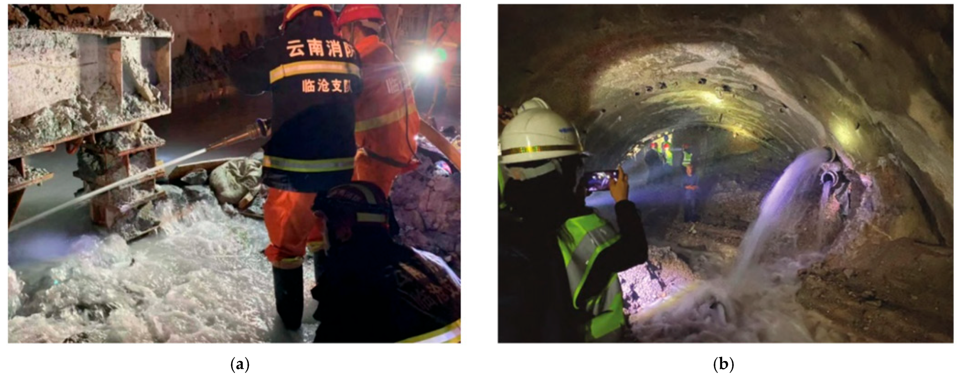
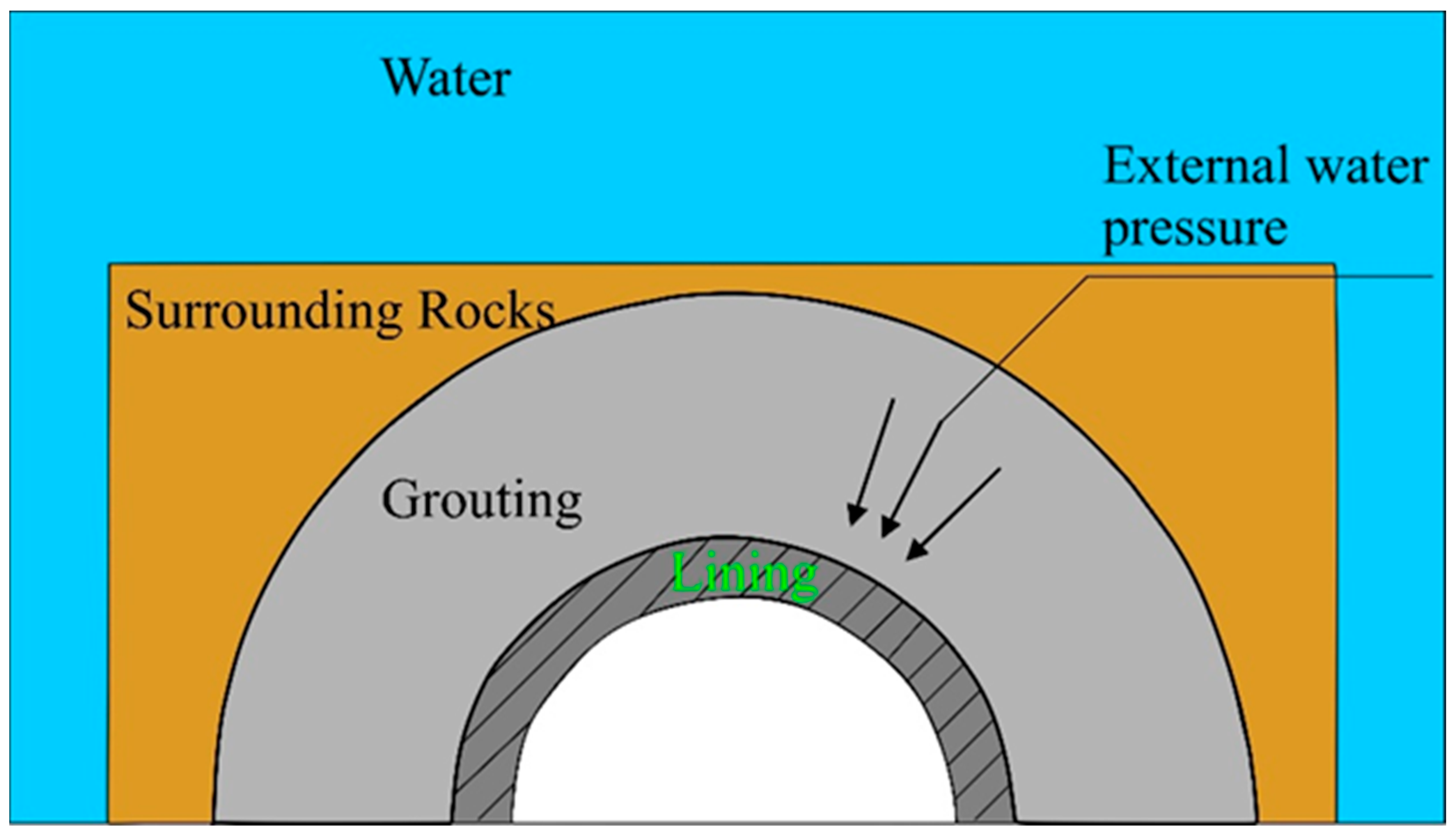
Since the beginning of the 21st century, the rapid expansion of transportation, inter-basin water transfer, and hydropower projects has accelerated the construction of deep-buried tunnels in complex geological settings [1,2,3]. Among the many engineering challenges encountered in such projects, high external water pressure has become one of the most critical factors affecting tunnel stability and construction safety, particularly for subsea tunnels (Figure 1). These tunnels are excavated in groundwater-rich environments with effectively continuous recharge [4,5]; therefore, seepage must be controlled mainly through drainage and pumping [6]. In drill-and-blast construction, external water pressure on the initial support refers to the water pressure acting on the outer surface of the shotcrete, representing seepage-induced forces transmitted through the surrounding rock and influenced by the support-rock interface condition [7]. During excavation and long-term operation, sustained pore pressure combined with progressive damage can increase leakage and safety risks [8,9,10]. This issue is further amplified because the surrounding rock mass is typically fractured, with seepage primarily controlled by interconnected joints and faults, and permeability that increases under high water pressure [11,12]. As a result, hydro-mechanical coupling plays a significant role, where excavation-induced unloading promotes fracture growth and water pressure build-up behind the initial support [13,14], leading to shotcrete cracking, increased seepage, hydraulic fracturing, and even water/mud inrush [15,16] (Figure 2). Therefore, clarifying fracture-controlled seepage mechanisms and reliably estimating external water pressure on initial support under coupled conditions is essential for subsea tunnel design [17].
Although tunnel seepage and lining water pressure have been studied for decades [18,19,20,21,22]. Most existing research focuses on hydraulic tunnels [23,24], and conventional water-bearing mountain tunnels, where the secondary lining is considered the primary pressure-bearing structure under relatively stable seepage conditions [25]. In such cases, the lining is continuous and relatively impermeable, and analyses commonly assume slow hydraulic evolution and largely intact lining-rock contact [24]. However, drill-and-blast subsea tunnels differ significantly. The initial support, typically made of shotcrete, rock bolts, and steel ribs, is installed immediately after excavation and remains temporary [26,27], often discontinuous, and prone to cracking, partial debonding, and uneven contact with the surrounding fractured rock [28]. Consequently, under high hydraulic head, the external water pressure acting on the initial support cannot be treated as a fixed hydrostatic load, but rather as an evolving response controlled by seepage redistribution and the changing support-rock interface condition. To better understand and predict the complex interaction between water pressure and tunnel support, numerous studies have investigated various approaches, including reduction coefficient approaches [29,30,31], analytical solutions [32,33], numerical simulations [34,35,36], physical models [37,38], and coupled seepage analyses [2,39,40,41].
Empirical reduction coefficient approaches are widely used in design because of their simplicity, treating external water pressure as a fixed proportion of the groundwater head based on code guidance or limited engineering experience [42]. It has significant limitations, especially in fractured rock environments [43]. This method typically assumes homogeneous media, steady seepage, and uniform permeability, which rarely hold true in complex subsea tunnel settings [44]. It also assumes a continuous lining, which is not applicable for drill-and-blast subsea tunnels, where the initial support is often temporary, discontinuous, and prone to cracking and debonding [24]. Furthermore, the method fails to account for dynamic changes in permeability due to excavation-induced stress redistribution and the evolving fracture networks within the surrounding rock [45]. Consequently, the reduction coefficient method can lead to an overestimation or underestimation of external water pressure, making it insufficient for accurately predicting the performance of initial support in high-pressure subsea tunnel environments [30].
Similarly, analytical solutions derived from axisymmetric Darcy seepage offer a valuable baseline understanding [46], but they depend on restrictive assumptions, homogeneous continua, steady laminar flow, invariant permeability, and continuous support-rock contact [42], which are rarely met in drill-and-blast tunnels where excavation damage, cavities, and imperfect contact alter the hydraulic boundary conditions [47].
Moreover, numerical simulations have become essential tools for modeling complex geometries and interconnected systems in subsea tunnels, offering flexibility and precision in simulating real-world conditions [22,48]. However, many current modeling methods rely on equivalent continuum models that assume constant permeability and treat the initial support as fully intact or perfectly bonded to the surrounding rock [24]. These assumptions fail to capture the dynamic nature of permeability changes caused by excavation-induced stress redistribution and fracture development [49,50]. Furthermore, drill-and-blast subsea tunnels feature temporary, discontinuous support systems that are prone to cracking, partial debonding, and uneven contact with surrounding fractured rock [51]. The resulting water seepage paths and load-transfer inefficiencies significantly alter the water pressure distribution, rendering these methods insufficient for accurately predicting external water pressure. This highlights the need for a mechanism-based approach to external water pressure in subsea tunnels, which remains a critical challenge in tunnel engineering [52].
Physical model testing also provides an important complementary approach for investigating external water pressure in tunnels, because it allows direct observation of seepage behavior, deformation patterns, and failure mechanisms under controlled hydraulic and structural conditions [53]. Recent model studies have shown that drainage capacity, blockage conditions, grouting reinforcement, and groundwater head significantly affect the magnitude and distribution of external water pressure acting on tunnel linings and supports [54,55]. However, despite these advantages, physical model testing remains constrained by similarity requirements, simplified boundary conditions, and the difficulty of simultaneously reproducing coupled seepage–stress–damage processes in fractured rock masses, making it more suitable for mechanism exploration and model validation than for direct engineering calculation of external water pressure [56].
The cubic-law concept of single-fracture seepage laws demonstrates that fracture aperture size directly determines flow capacity at the fracture scale, which means that even minor stress-driven changes to aperture size result in drastic shifts to permeability [57,58]. The nature of natural fractures presents a rough and heterogeneous surface, which enables flow to create specific channels while permeability changes according to normal stress, shear dilation, and damage [59,60]. The basic element level shows that seepage and mechanical behavior are fundamentally linked, with their properties interrelated.
There are two general seepage models widely used for upscaling of fracture behavior in fractured rock mass. Continuum equivalent models consider the fractured rock as a porous medium with an averaged (generally tensorial) permeability and allow for a relatively low-cost simulation [61], but may lack the representation of localized and fracture-dominated flow and pressure concentration [62]. Discrete fracture network (DFN) models characterize individual fracture sets and their connectivity, and are capable of representing anisotropic and channelized seepage [63], but at the cost of high demand for detailed geological information, computationally intensive, and are usually with limited coupling to mechanical evolution [64,65]. Therefore, neither approach may be suitable for drill-and-blast subsea tunnels, where excavation damage, opening/closure of fractures, and the creation of new fractures constantly change flow paths and pressure redistribution equally both around and between the fractures [66].
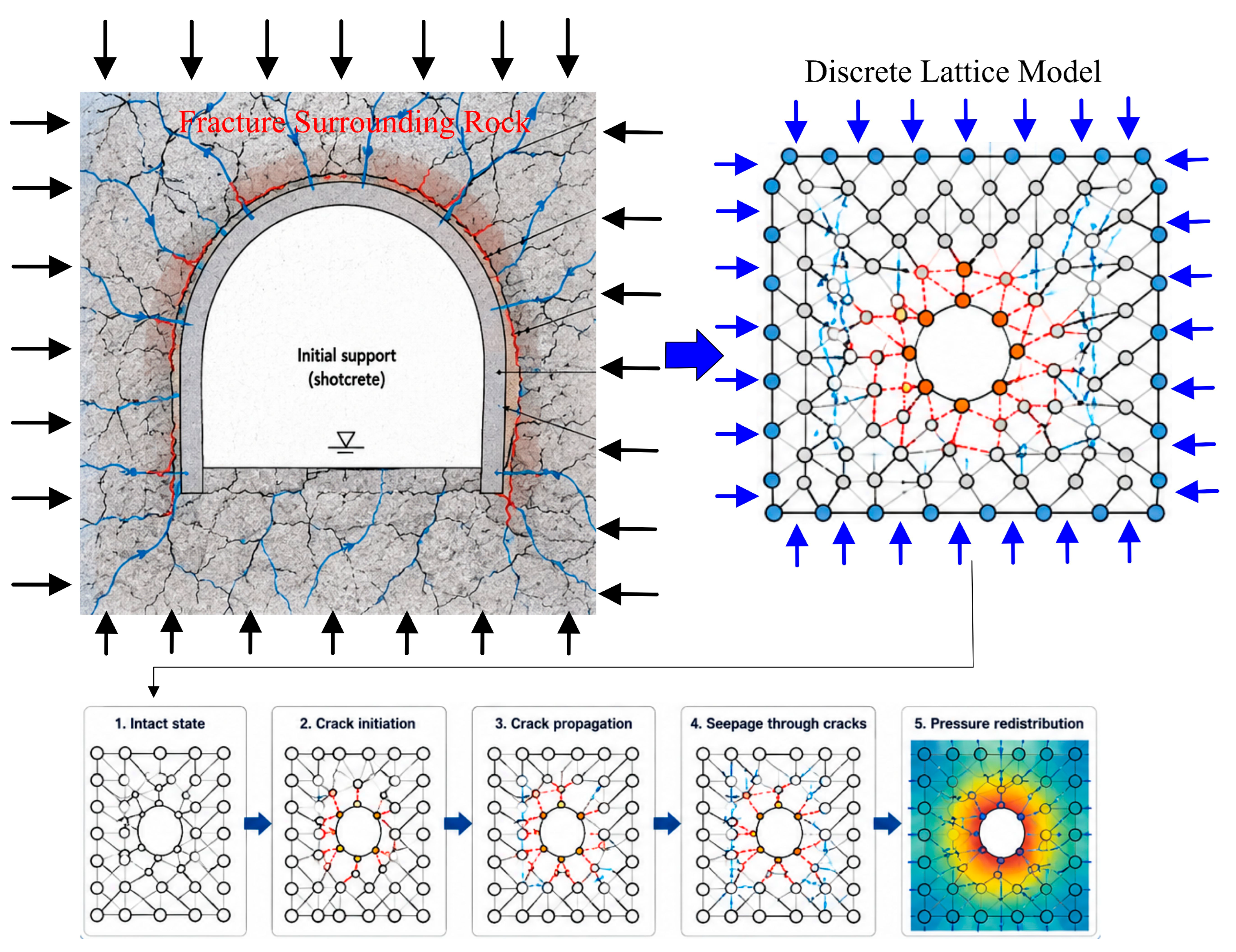
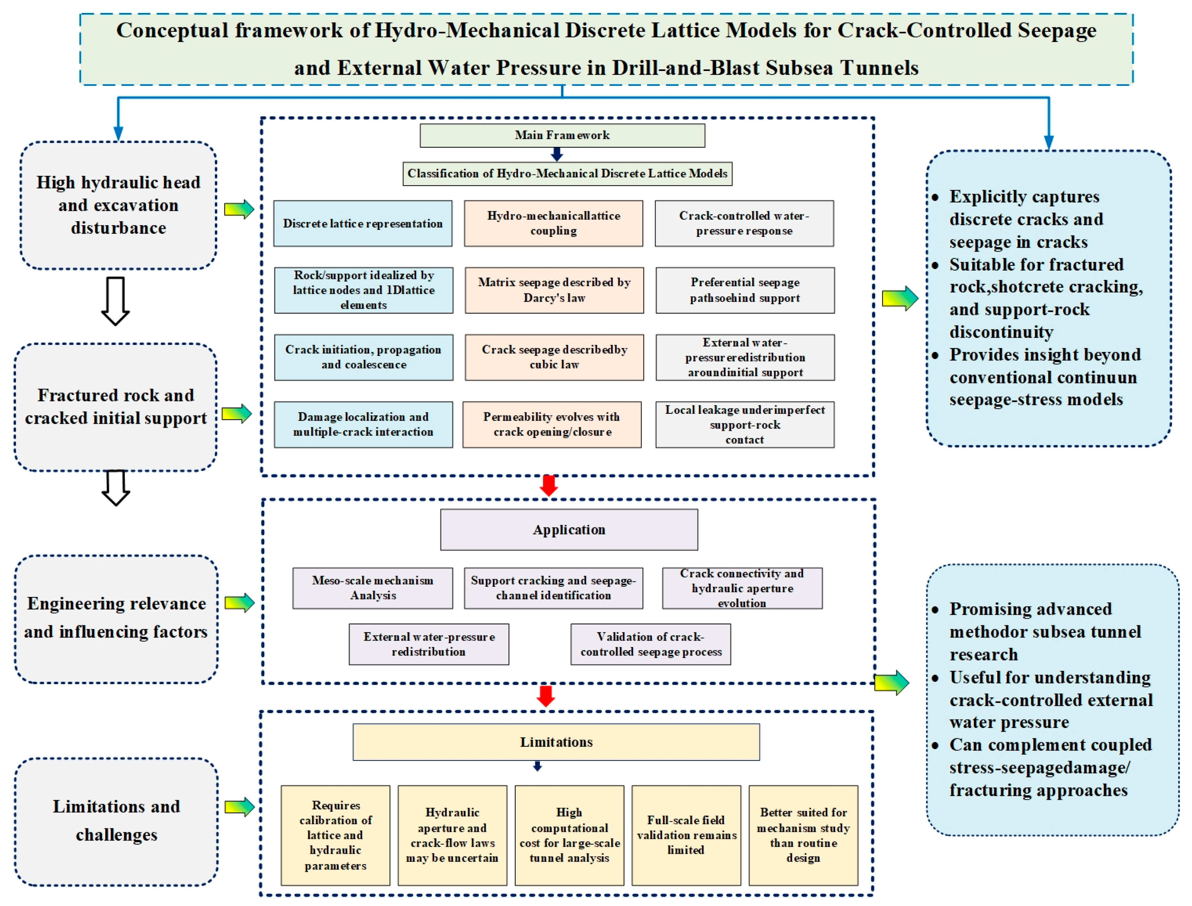
These limitations have motivated advanced coupled models. Unlike simplified seepage–stress formulations, stress–seepage–damage and stress–seepage–fracturing models can account for damage-induced permeability evolution and crack propagation, providing a more realistic framework for predicting external water pressure on initial support under high-pressure subsea conditions. Moreover, recent discrete numerical models, especially hydro-mechanical discrete lattice models, can explicitly simulate crack initiation, propagation, coalescence, and seepage through connected cracks. This is useful for drill-and-blast subsea tunnels, where blasting damage, fractured rock, cracked shotcrete, and imperfect support–rock contact may create localized seepage channels under high hydraulic head.
Consequently, this review seeks to systematically and critically examine prior approaches to the prediction of external water pressure acting on the initial support of subsea tunnels constructed using the drill-and-blast method. Unlike previous studies that mainly focus on secondary lining, hydraulic tunnels, or general tunnel seepage control, this review emphasizes the early support stage of drill-and-blast subsea tunnels, where shotcrete, rock bolts, steel ribs, fractured surrounding rock, and imperfect support–rock contact interact under high groundwater pressure. As shown in Figure 1, deep-buried and subsea tunnels are commonly subjected to high external water pressure during construction and operation, while Figure 2 illustrates the severe water inrush hazards that may occur during excavation under high groundwater pressure. The novelty of this review lies in treating external water pressure not as a fixed hydrostatic load or a simple reduced pressure, but as an evolving hydro-mechanical response controlled by fractured rock seepage, excavation-induced stress redistribution, support cracking, damage-induced permeability evolution, and support–rock interaction. Accordingly, this review synthesizes and compares empirical reduction coefficient methods, theoretical analytical solutions, numerical simulations, physical model tests, advanced coupled stress–seepage–damage/fracture models, and hydro-mechanical discrete lattice models. By identifying the limitations of existing approaches and clarifying future development trends, this work aims to provide a mechanistic basis for more rational calculation methods and safer initial support design in high-water pressure drill-and-blast subsea tunnels.

2. Review Methodology

To conduct this review, extensive searches were performed in major international and regional scientific databases, including Web of Science, Scopus, ScienceDirect, SpringerLink, ASCE Library, Google Scholar, and CNKI, to retrieve relevant academic and technical literature. The retrieved documents included peer-reviewed journal articles and review papers, as well as selected conference papers, technical reports, and book chapters that provided important methodological, theoretical, or engineering information. The search was carried out using combinations of keywords including “subsea tunnel,” “undersea tunnel,” “underwater tunnel,” “drill-and-blast tunnel,” “external water pressure,” “lining water pressure,” “water inflow,” “water inrush,” “initial support,” “shotcrete support,” “fractured rock mass,” “seepage,” “grouting,” “drainage,” “hydro-mechanical coupling,” “stress-seepage-coupling,” “damage-induced permeability,” and “hydraulic fracturing.”
The literature search mainly considered publications from 2000 to 2026, as this period covers major developments in subsea tunnel construction, fractured rock seepage analysis, numerical simulation, physical model testing, and coupled hydro-mechanical modeling. Earlier classical studies were also included when they provided fundamental seepage theories, analytical solutions, or widely used calculation methods for tunnel external water pressure. Studies focusing on external water pressure, lining water pressure, seepage control, water inflow, support response, fractured rock seepage, grouting, drainage, support–rock interaction, and coupled stress–seepage–damage or stress–seepage–fracturing models were prioritized.
To broaden the methodological and mechanistic basis of the review, relevant studies from mountain tunnels, hydraulic tunnels, loess tunnels, coal-mine roadways, and water-rich fault-zone tunnels were also considered when they provided transferable mechanisms related to seepage redistribution, drainage pressure relief, grouting reinforcement, lining response, fractured rock flow, or hydro-mechanical coupling. However, studies unrelated to tunnel engineering, studies dealing only with general groundwater hydrology without tunnel applications, duplicated sources, and documents lacking sufficient methodological or technical details were excluded.
Relevant information was mainly extracted from the abstracts, methods, results, discussions, and conclusions of the selected publications. The extracted information included tunnel type, geological and hydraulic conditions, support or lining system, calculation method, model assumptions, water pressure distribution, water-inflow characteristics, drainage and grouting effects, support deformation, cracking behavior, and model limitations. Finally, the selected literature was classified into reduction coefficient methods, analytical solutions, numerical methods, physical model testing, fractured rock seepage models, advanced coupled models, and hydro-mechanical discrete lattice models for comparative analysis.

3. Key Research Areas and Methodologies

The external water pressure on the initial support of a tunnel is shown in Figure 3. Currently, the external water pressure on the initial support of a tunnel can be determined using various methods, including the reduction coefficient method, theoretical analytical method, numerical analysis method, and physical model testing method.

3.1. Reduction Coefficient Method

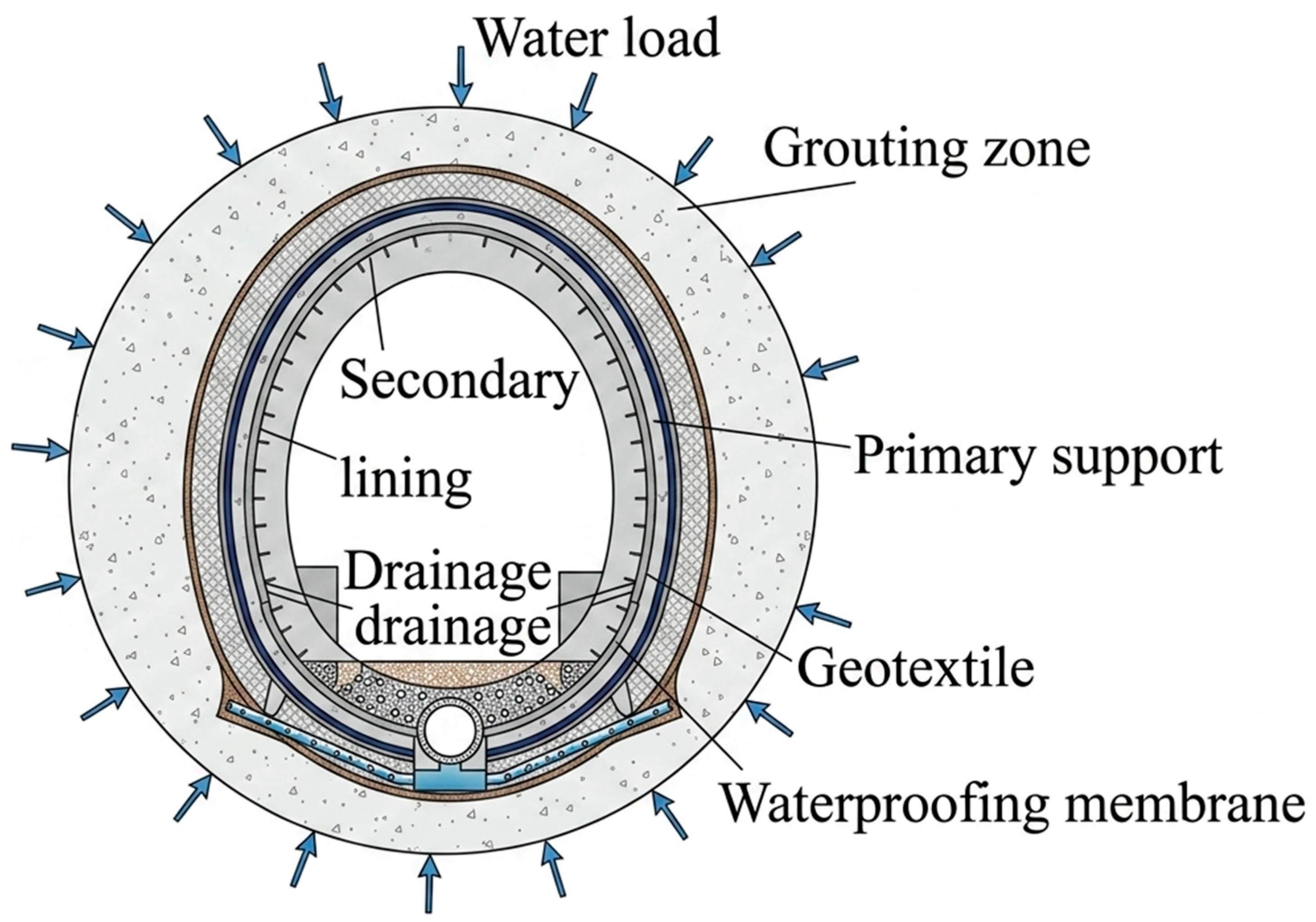
The reduction coefficient method is one of the most commonly adopted approaches for estimating external water pressure acting on tunnel linings and supports, particularly in practical engineering design [30]. This method is suitable for mountain tunnels under high water levels and consists of a grouting zone, drainage devices, and a waterproofing membrane as shown in Figure 4. The grouting zone is designed to reduce the seepage discharge into the tunnel, the drainage devices are embedded behind the lining to alleviate the water pressure on the lining, and the waterproofing membrane is laid between the primary support and the waterproofing secondary lining. In this method, the external water pressure is expressed as a fraction of the hydrostatic pressure corresponding to the groundwater head, where the fraction, referred to as the reduction coefficient, is intended to reflect the pressure relief effect provided by drainage measures, grouting reinforcement, and lining permeability [31]. Owing to its simplicity and convenience, the method has been widely used in design codes and engineering practice.
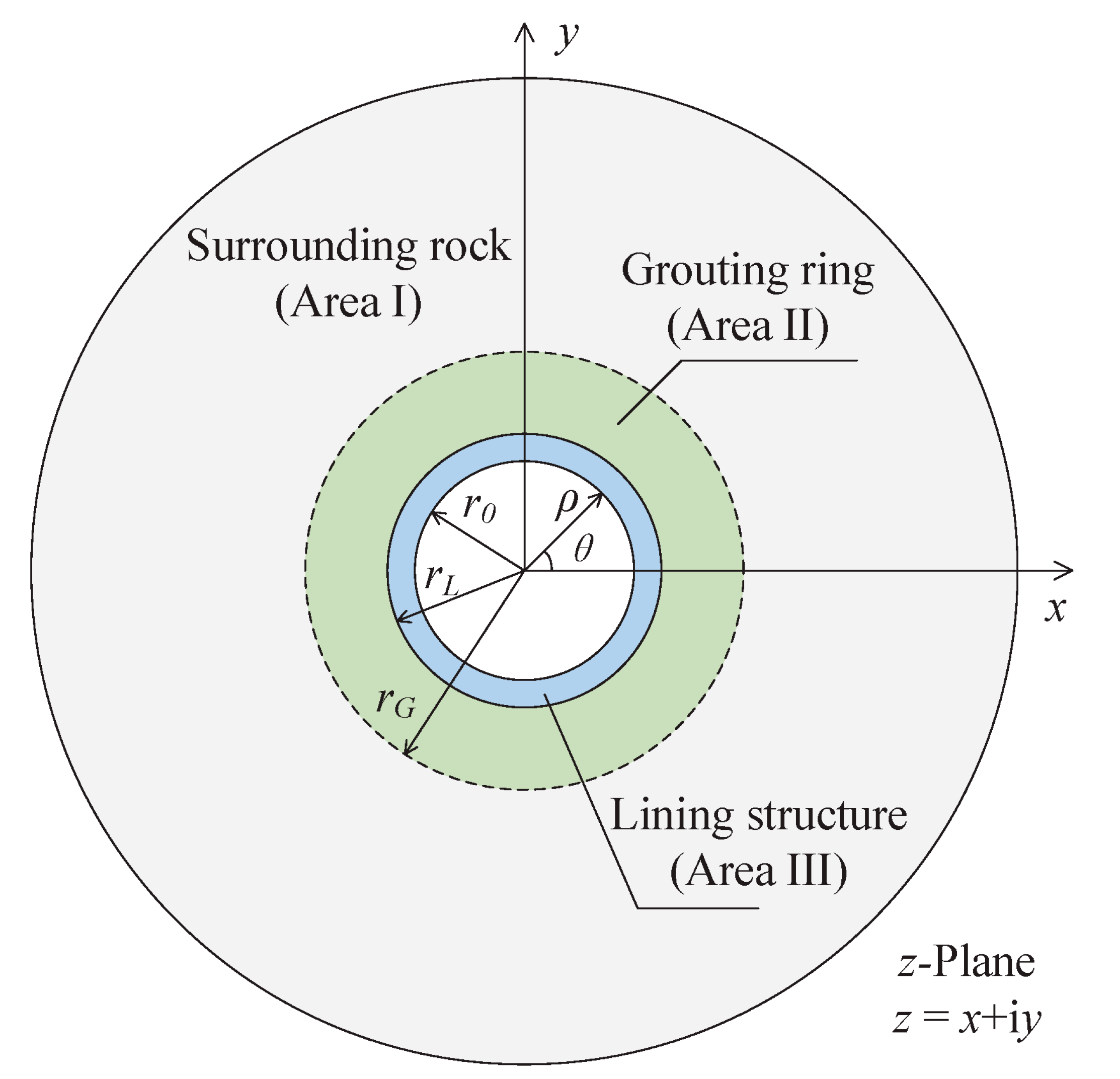
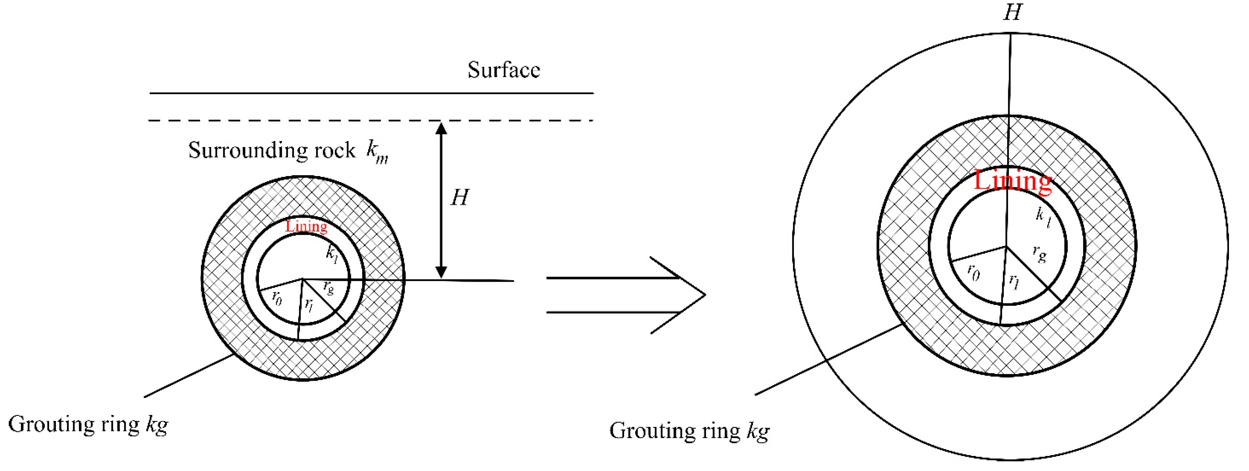
The reduction coefficient method is based on the theoretical basis of simplified seepage assumptions between the surrounding rock mass and the lining system, and they are treated as concentric cylindrical layers with steady radial flow, which is a major discrepancy from reality [43] as illustrated in Figure 5. Relationships between the external water pressure and surrounding rock permeability, lining permeability, grouting thickness, and drainage capacity are usually given by analytical solutions based on Darcy’s law [47]. Researchers have proposed various expressions for the reduction coefficient, which represents the extent of reduction in the water pressure acting on the tunnel support system due to seepage control measures [42].
This method has been standardized in engineering applications for tunnels with simple hydrogeological and engineering geological conditions. As per Design Code for Hydraulic Tunnels (SL 279-2016) [69], the external water pressure acting on tunnel linings and supports can be calculated by following the reduction coefficient method [70] by Equation (1):
pe = βeγwHe
where pe is the external water pressure (kN/m2), βe is the external water pressure reduction coefficient, γw is the unit weight of water (kN/m3), and He is the acting hydraulic head measured from the groundwater level to the tunnel center (m).
For concrete-lined tunnels, the reduction coefficient βe is generally selected based on the groundwater activity of the surrounding rock and its influence on rock mass stability, as specified in the design code. For hydraulic tunnels equipped with drainage facilities, the external water pressure may be further reduced depending on the effectiveness of the drainage system, with reduction values commonly determined through engineering analogy or seepage calculation analysis according to the Table 1 Code for Design of Hydraulic Tunnels (SL 279-2016).
Currently, most engineering designs use the reduction coefficient method to estimate external water pressure. Studies have shown that karst cavities, groundwater pressure, and grouting conditions strongly influence lining water pressure and tunnel stability [25]. Wang et al. [67] conducted theoretical and experimental investigations on external water pressure acting on tunnel linings under high groundwater conditions and reported that drainage conditions strongly influence the water pressure behind the lining, demonstrating that pressure reduction depends on the seepage environment and drainage efficiency. Xu et al. [71] examined the effects of the grouting ring, lining hydraulic conductivity, and grouting-ring thickness on external hydraulic pressure and its reduction coefficient, and established a simplified formula for estimating the reduction coefficient under different lining and grouting conditions. Zhao et al. [29] further developed and applied a new reduction coefficient from the Qingdao Metro Line 8 subsea tunnel, under a total hydraulic head of approximately 52 m. The calculated maximum external water pressure on the initial support was 134 kPa, while field-monitored stable pressures were generally below 50 kPa, corresponding to less than 10% of the total head. This demonstrates that the pressure acting on the support may be far lower than the full hydrostatic pressure when water blocking and drainage-control measures are effective. The reduction coefficient method is primarily a design support concept for load–structure design in engineering applications [72]. External water pressure is not considered a fully developed hydrostatic load, but rather a reduced load based on empirical or semi-analytical coefficients [42]. This method has demonstrated acceptable results for tunneling in almost intact rock mass or under moderate groundwater pressure, particularly when certain drainage systems work well, and the permeability condition remains roughly constant over long time periods.

Limitations

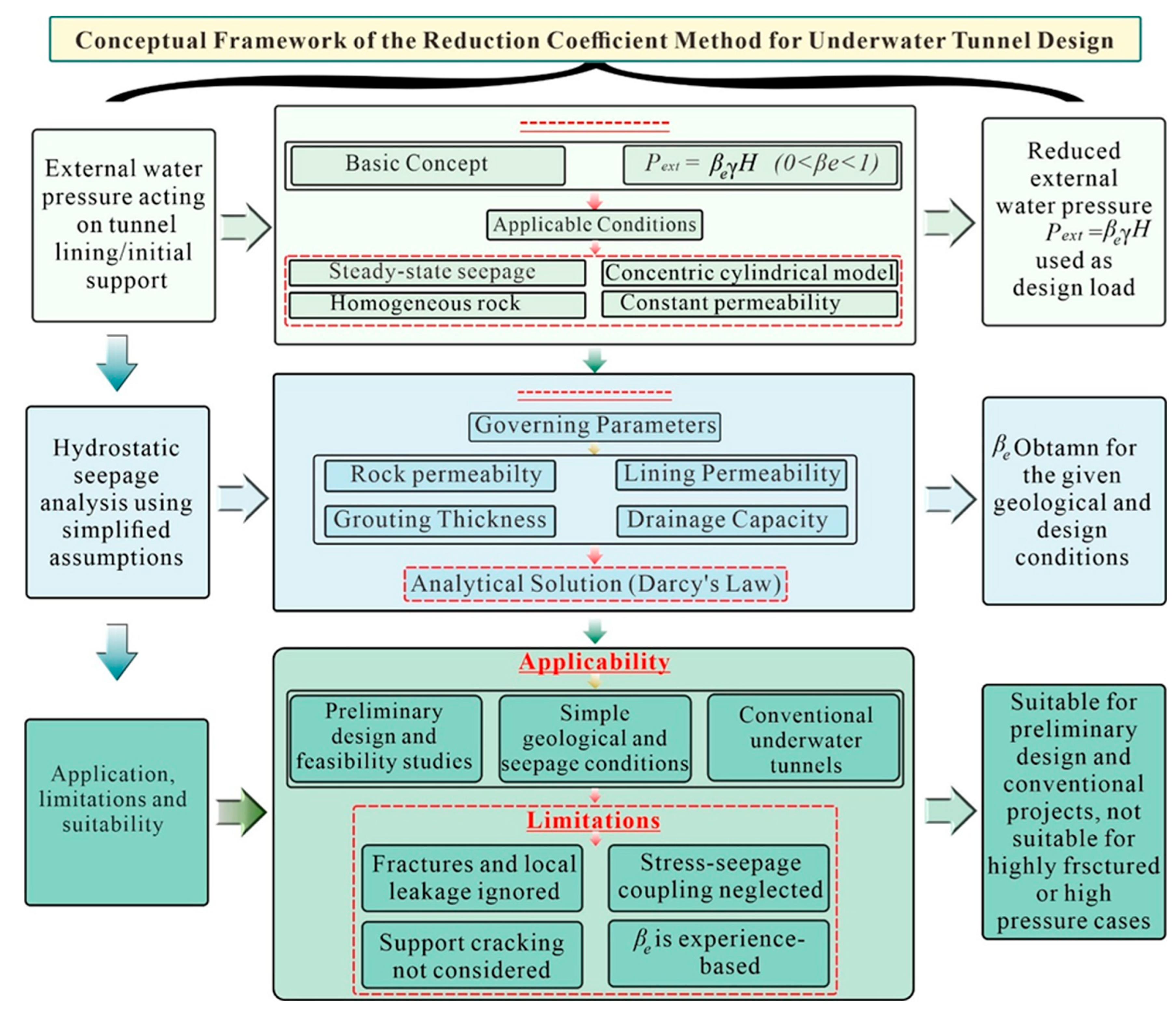
The main limitation of the reduction coefficient method is that the coefficient is usually taken from the design codes, engineering experience, engineering analogy, or simplified seepage calculations. This approach is convenient for initial design, but is not sufficient to represent the site-specific hydrogeological complexity for a drill and blast subsea tunnel [43]. It is, in particular, limited in its capability to model fracture-controlled seepage, excavation-induced permeability evolution, local pressure concentration, and leakage around the cracked or discontinuous initial support [42]. Furthermore, the method is not suitable to evaluate the external water pressure acting on the initial support system because cracking of shotcrete and the change in the condition of the contact with the support rock may create local leakage channels and non-uniform pressure distributions that contradict the assumption of the uniform pressure reduction and intact support [29]. The water pressure around the perimeter of the tunnel is usually assumed to be reduced to a single coefficient (the external water pressure), and the effects of imperfect support–rock contact are usually simplified [73]. This method is thus applicable for first-order estimation, but is not considered to provide accurate assessment of the external water pressure in high hydraulic head and fractured rock conditions [42,43]. The overall approach to the calculation, main assumptions, governing parameters, conditions of application and main limitations of the reduction coefficient method are shown in Figure 6.

3.2. Theoretical Analytical Method

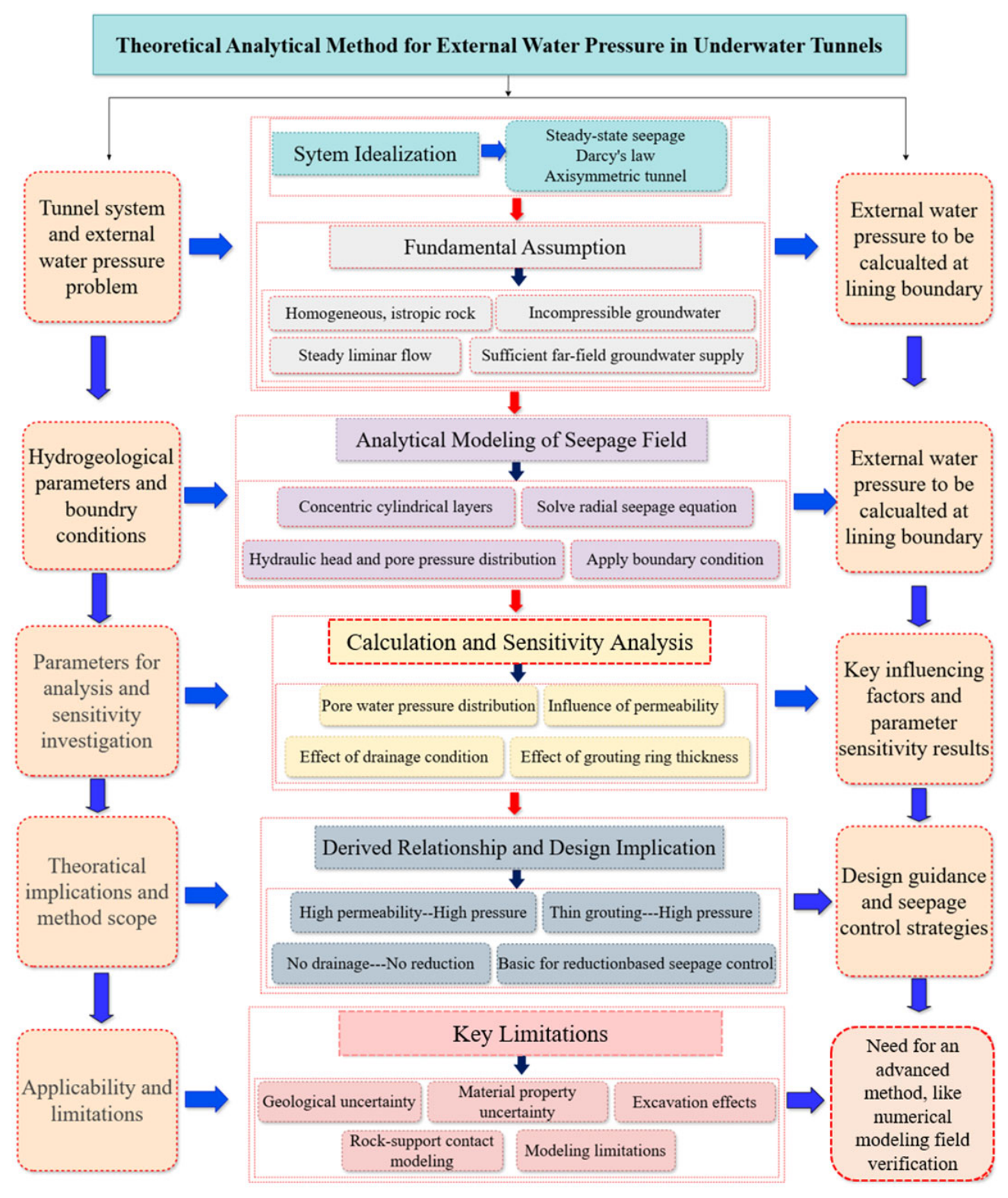
Theoretical analytical methods aim to calculate external water pressure acting on tunnel linings and supports by deriving closed-form solutions based on seepage theory and continuum mechanics [74]. These methods typically idealize the tunnel and surrounding rock as an axisymmetric system and describe groundwater flow using Darcy’s law under steady-state conditions [75]. By solving the governing seepage equations, analytical expressions for pore water pressure distribution and external water pressure can be obtained, providing direct physical insight into the relationship between hydrogeological parameters and tunnel water load [76].
In general, theoretical analytical methods are established under the following fundamental assumptions: (1) the surrounding rock is treated as an isotropic, homogeneous, and continuous medium, and both the water-bearing medium and groundwater are assumed to be incompressible; (2) the far-field groundwater supply is sufficient, such that tunnel drainage does not induce a decline in regional groundwater level; and (3) seepage in the surrounding rock occurs as steady laminar flow and strictly obeys Darcy’s law. Based on these assumptions, the external water pressure acting on tunnel linings can be derived using classical seepage theory [77,78]. External water pressure calculation is shown in Figure 7.
Under the axisymmetric seepage framework, the tunnel, grouting ring, and surrounding rock are commonly simplified as concentric cylindrical layers [79], as shown schematically in Figure 7. Pore water pressure in analytical solutions can be described by solving the radial seepage equation, wherein the permeability contrasts among the lining, grouting ring, and surrounding rock are taken into account [80]. An example of a simple analytical expression for pore water pressure might be written as Equation (2).
p = r w H n r 1 r 0 ln r 1 r 0 + k 1 k m ln H r g + k 1 k g ln r g r 1 = β r w H
where k1, km, and kg denote the permeability coefficients of the lining, surrounding rock, and grouting ring, respectively; r is the radial distance from the tunnel center; r0 and r1 are the inner and outer radii of the lining; rg is the outer radius of the grouting ring; h is the hydraulic head at radius r; and H is the far-field hydraulic head.
Many general patterns have been identified regularly through theoretical and analytical analysis. The external water pressure acting on the lining increases with the increase in lining permeability, the increase in surrounding rock permeability, and the increase in grouting ring permeability [81]. The external water pressure is high when the grouting ring is thin, and only through grouting, if no drainage is provided, the external water pressure will not be reduced [67]. Without drainage, external water pressure on the lining is equal to the hydraulic head difference between the lining and the groundwater level [56]. These findings have offered significant theoretical backing for reduction-based design concepts and seepage control strategies.
Building on traditional seepage theory, [82,83] had systematically derived the forces on tunnel linings under small-deformation conditions based on the relative stiffness method, accounting for the seepage-induced loads into lining stress analysis. They also studied the impact of exterior drainage systems and water-supply fault zones on seepage field distribution and exterior hydraulic stress. For non-circular tunnels, the concept of equivalent radius can be used to convert the cross-sectional dimensions of the tunnel into those of a circular tunnel for calculation purposes [84].
Wang et al. [67] developed analytical models for external water pressure acting on tunnel lining and discusses how model assumptions affect predicted pressure distributions, effectively treating the pressure as an applied boundary force and modifying results based on permeability and drainage effects. Liu et al. [85] derived analytical expressions for lining water pressure in the conditions of curtain grouting, combining empirical observations with theoretical analysis. El Tani [86] summarized the commonly used formulas for calculating water inflow, and compared the methods of Goodman, Karlstud, Rat, Lombardi and others [19,87,88]. Jiang and Tang [89] proposed a general approximate method for the groundwater response problem caused by water level variation. Tang et al. [90] gave an approximate analytical solution to the Boussinesq equation with a sloping water-land boundary. Tang and Jiang [91] gave an analytical solution for the problem of exit point evolution on the seepage face in the unconfined aquifer with a sloping interface. Liang and Zhang [92] presented an analytical method for groundwater recharge and discharge estimation.
Although the theoretical analytical methods have a clear theoretical framework and physical interpretability, the application scope of the theoretical analytical methods is inherently limited to subsea tunnels excavated in fractured rock masses under high water pressure. The assumption of homogeneity, isotropy, and steady seepage is seldom met in fractured geological settings, where groundwater flow is primarily controlled by discrete fractures rather than continuous pore space, and analytical formulas derived under homogeneous conditions may deviate from actual heterogeneous responses [93]. Additionally, coupling effects between seepage and deformation are generally omitted in classical analytical methods, and recent extensions that include hydro-mechanical coupling illustrate the limitations of uncoupled analytical frameworks [94]. Analytical solutions also typically assume undamaged tunnel linings and continuous support–rock contact, which do not represent crack initiation and local leakage in drill-and-blast subsea tunnels, further limiting their applicability [95].

Limitations

Theoretical analytical methods provide clear physical interpretation and are useful for identifying the influence of key parameters such as hydraulic head, permeability contrast, lining permeability, grouting-ring thickness, and drainage conditions [96,97]. However, their main limitation lies in the idealization required to obtain closed-form solutions. Most analytical models simplify the tunnel as an axisymmetric or equivalent circular system and represent seepage through prescribed boundary conditions. These simplifications make it difficult to describe irregular excavation profiles, local overbreak or underbreak, nonuniform grouting, and discontinuous contact between initial support and fractured surrounding rock [42,43,95,96,97,98]. As a result, analytical methods are best used as benchmark solutions or sensitivity-analysis tools, rather than as standalone calculation methods for complex drill-and-blast subsea tunnels. Figure 8 summarizes the overall dependence of the theoretical analytical parameters.

3.3. Numerical Analysis Method

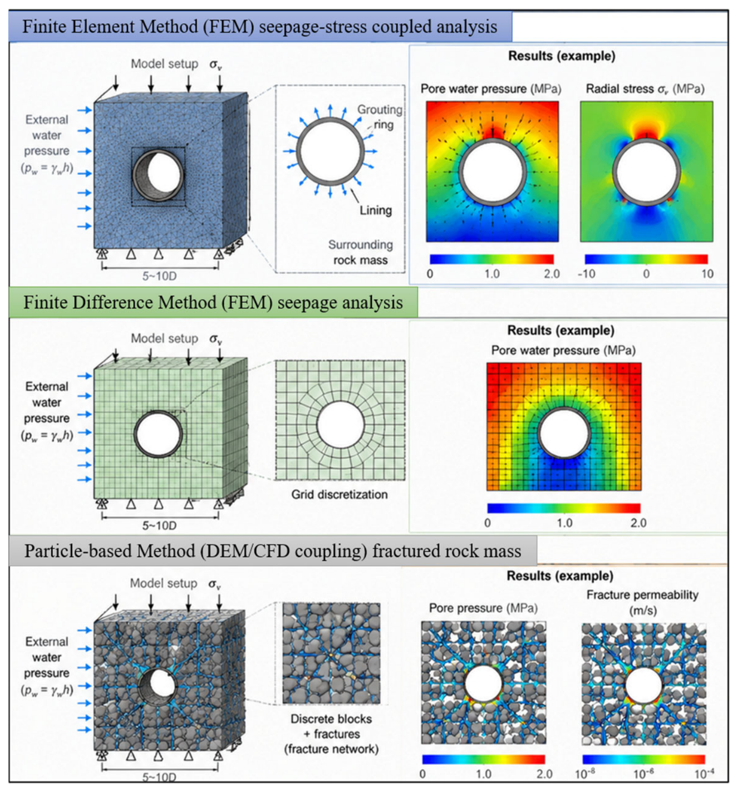
Numerical analysis methods have become an indispensable tool for the calculation of external water pressure acting on tunnel linings and supports, especially in the case of complex geological and hydrogeological conditions resulting in the non-applicability of analytical solutions [95]. As shown in Figure 9, numerical approaches, which include the finite element method (FEM), the finite difference method, and particle-based methods, allow the groundwater flow, stress redistribution, and structural response of the support system under realistic boundary conditions to be simulated by discretizing the surrounding rock mass, support system, and seepage field [99,100,101]. Numerical analysis is more flexible than empirical or theoretical analytical methods to represent heterogeneous materials, complex geometry, and nonlinear behavior [102,103].
The finite element method is one of the common numerical methods for solving external water pressure in tunnels. The main advantage of this method is its consideration of the heterogeneity and discontinuity of the rock mass [104]. FEM can be used to solve the coupled equations describing stress, deformation, and seepage, which can provide the value and spatial distribution of rock mass stress, deformation, and pore water pressure, so as to study the deformation and failure mechanism of the tunnel under the condition of high-water pressure [105]. In early numerical studies, attention was mainly paid to the seepage problem, in which the surrounding rock was treated as a porous medium with a given permeability, and the pore water pressure distribution around tunnels was computed [2]. Although such models increased our ability to estimate external water pressure by accounting for layered geological conditions and permeability variation, they treated seepage and mechanical behavior as independent.
In order to address this limitation, seepage–stress coupled numerical models were then established. These models simulate pore water pressure and stress fields simultaneously, enabling the consideration of seepage-induced variations in effective stress and deformation, and excavation-induced stress redistribution, both of which can influence the seepage response [11]. Finite element analyses comparing various combinations of both grouting ring depths and the orders of magnitude of permeability reduction to the external water pressure distribution for different grouting parameters [106,107]. Finite element studies have shown that saturated rock mass porosity and permeability evolve with stress redistribution and damage, and that this evolution significantly influences seepage behavior effects that must be included in seepage analysis rather than treated as fixed parameters [17,108,109].
Further developments have sought to improve the representation of fractured rock masses. Liu et al. [42] and Huang et al. [43] adopted an equivalent continuum fracture network coupled seepage model, in which rock mass integrity, permeability, and fracture development degree were jointly considered to numerically simulate tunnel seepage fields. Their results provided estimates of external water pressure and verified the rationality of existing drainage systems. Unlike analytical solutions that often rely on equivalent radius concepts for non-circular tunnels, numerical methods allow the tunnel cross-section geometry to be modeled directly [110]. This capability has been used not only to analyze seepage fields and external water pressure around non-circular tunnels, but also to verify the applicability of equivalent radius assumptions used in analytical methods [74].
Numerical analysis has also been widely applied to investigate the influence of external water pressure on lining forces. Shin et al. [111] analyzed changes in internal lining forces under deteriorating drainage conditions using finite element calculations and proposed a design curve for estimating external water pressure loads effect on linings. Finite element analyses were carried out of the Bangkok Blue Line South Extension subway tunnel by Arjnoi et al. [112] to study the external water pressure distribution, seepage field characteristics and lining forces subjected to various drainage configurations. They found that fully drained conditions in twin tunnels could reduce the maximum compressive stress by around 30% and the maximum tensile stress by nearly 55%.
In spite of these scientific improvements, numerical analysis results are very sensitive to the model assumptions and parameter selection [113,114]. Two principle factors are especially crucial: correct representation of geological conditions (e.g., lithological contacts, and the spatial arrangement of faults, joints, and fractures) and appropriate characterization of rock mass properties (e.g., deformational characteristics, strength, seepage properties, and failure laws under coupled stress–seepage conditions) [115]. In the real process of excavation of a tunnel, overbreak and underbreak usually lead to connected or half-connected gaps between the surrounding rock mass and the tunnel support, and even become the seepage channels along the outer edge of the lining [82,116]. They have profound effects on lining forces and on external water pressure distributions.
Thus, it is essential to represent the contact relationship between the surrounding rock and the tunnel support in numerical analysis [117,118]. Research has indicated that overlooking the contact relationship results in an overestimation of the lining’s load-bearing capacity, while overly simplified contact assumptions may lead to safety factors that do not reflect real conditions [119,120]. These challenges are especially significant in drill-and-blast subsea tunnels, where cracking and debonding of initial support are frequent under high water pressure.
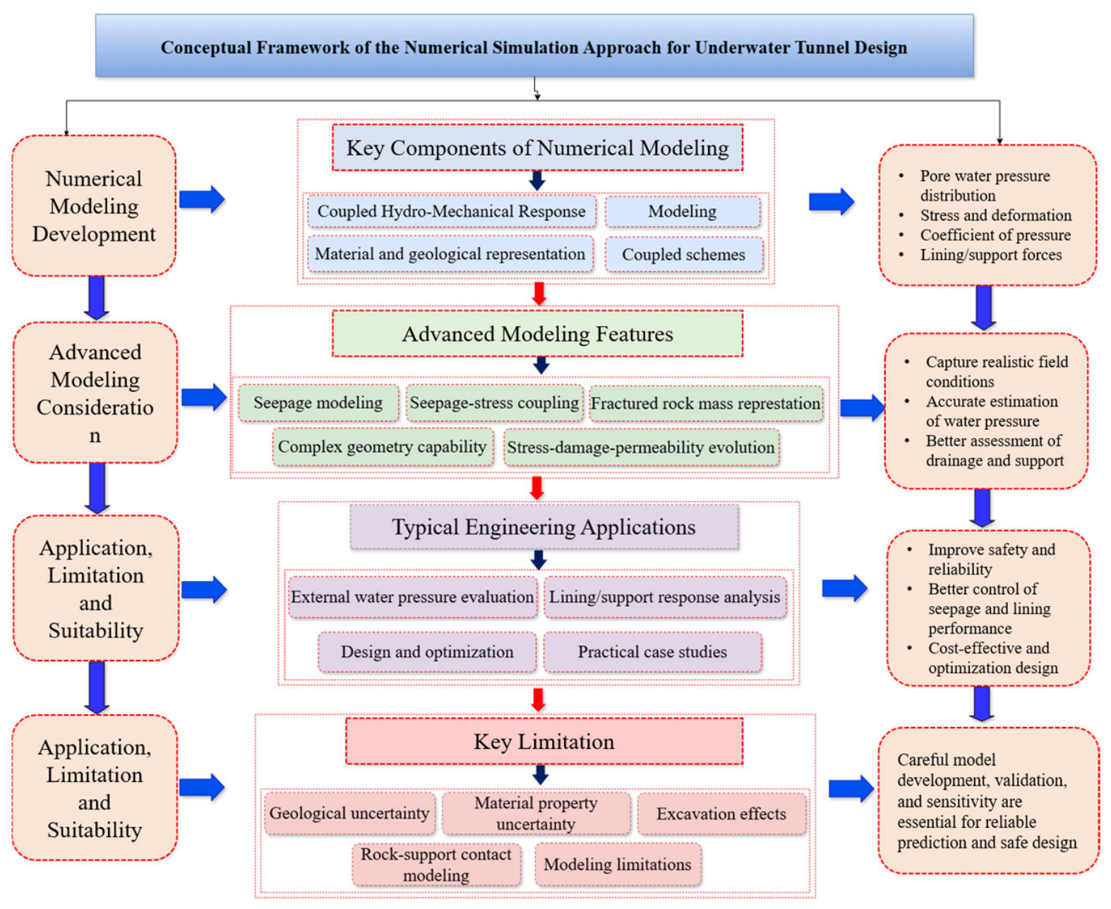
For highly fractured rock masses, particle-based methods offer an alternative numerical approach [121]. Numerical simulations of coupled particle-fluid models have shown that fracture development, fluid flow interaction, and evolution of permeability in fractured rock systems can be captured. For instance, simulations that integrate the discrete element methods with computational fluid dynamics (CFD) have been carried out for modeling fluid-driven fracture propagation and changing seepage characteristics in rock masses, which are not easily captured by continuum-based models [122,123]. The overall conceptual framework of the numerical simulation approach for underwater tunnel design is summarized in Figure 10, which outlines the model development, advanced modeling features, applications, and limitations.

Limitations

Numerical analysis methods overcome many geometric and boundary condition restrictions of empirical and analytical approaches, and they are valuable for simulating seepage fields, stress redistribution, support response, and water pressure distribution around tunnels [124]. Their main limitation is that the reliability of the results depends strongly on model assumptions, constitutive laws, boundary conditions, mesh quality, and input parameters. In fractured subsea rock masses, permeability, fracture connectivity, support cracking, and support–rock contact conditions are often difficult to characterize accurately. If these factors are simplified, the numerical model may produce visually convincing results without accurately representing the real hydro-mechanical mechanism [125]. Therefore, numerical analysis should be supported by geological investigation, laboratory testing, field monitoring, and sensitivity analysis before being used for design decisions.

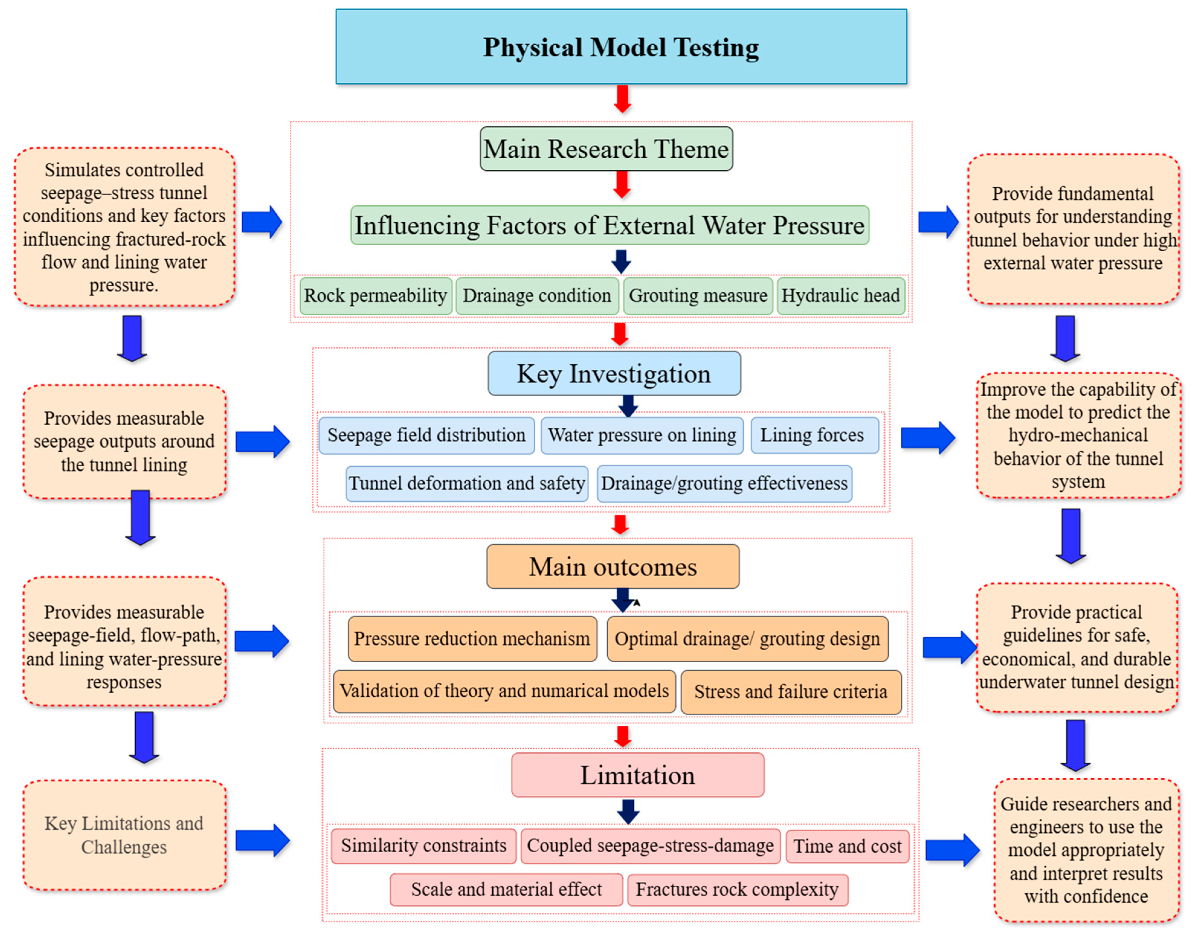
3.4. Physical Model Testing

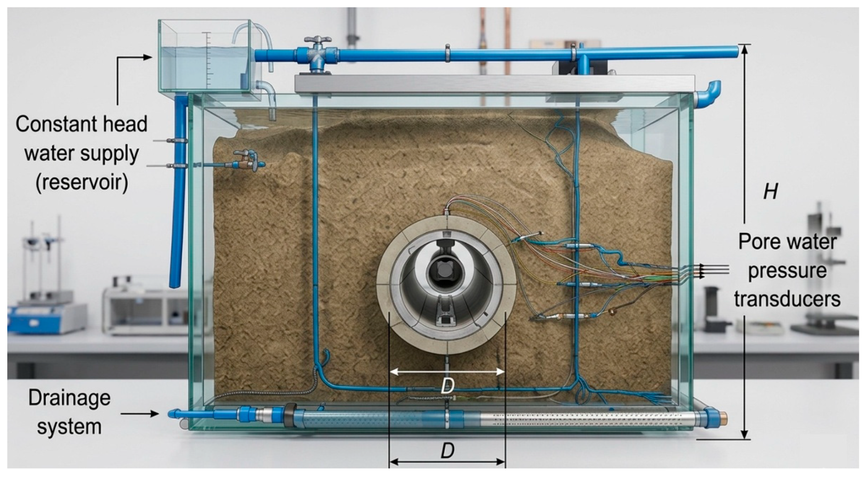
Laboratory-based physical model testing offers a relevant experimental framework for studying external water pressure on both tunnel linings and supports [126]. Scaled tunnel models can be used to design hydraulic boundary conditions, surrounding rock structures, and lining systems corresponding to the experimental objectives, built of rocks or artificial materials with known permeability and mechanical properties [127] as shown in Figure 11. Seepage pressure heads at different locations can be easily measured, which helps observe seepage behavior, deformation patterns, and failure mechanisms, which is not the case with purely analytical or numerical methods [13]. Consequently, physical model testing has been widely used as a complementary tool to validate theoretical assumptions and numerical simulations related to external water pressure in tunnels [128].
(1)
Influencing Factors of External Water Pressure
One of the primary objectives of physical model testing is to investigate the distribution characteristics of the seepage field in deep-buried tunnels and to identify the dominant factors influencing external water pressure [129]. By systematically varying parameters such as surrounding rock permeability, drainage conditions, grouting measures, and hydraulic head, model tests enable quantitative and qualitative evaluation of the relative importance of these factors and provide guidance for seepage control design [129].
Experimental and model studies have also investigated the influence of drainage systems on the distribution of external water pressure’s effect on tunnel linings. For example, physical model tests and three-dimensional printing-based experiments have been used to simulate railway tunnel drainage structures and evaluate the influence of drainage capacity and blockage conditions on lining water pressure. The results indicate that improvements in drainage capacity can significantly reduce external water pressure’s effect on the lining, while drainage blockage may lead to increased water pressure and unfavorable stress redistribution in the tunnel structure. It is also worth noting that drainage conditions can affect the spatial distribution pattern of water pressure around the lining and thus affect the deformation behavior of the tunnel invert when groundwater conditions are high, highlighting the importance of drainage design in controlling water pressure and ensuring tunnel stability under high groundwater conditions [130,131].
Wang et al. [67] studied the high groundwater conditions on the tunnel linings both theoretically and experimentally, and concluded that the water pressure distribution and magnitude in the drainage conditions had a significant impact on the water pressure behind the linings. They found that a good drainage system can significantly reduce the lining water pressure, but poor drainage can result in pressure build-up and high loading on the structures. Building on this concept, Zhao et al. [29] proposed a modified reduction coefficient for estimating external water pressure acting on subsea tunnel linings and demonstrated that the reduction coefficient is strongly controlled by factors such as groundwater head, drainage efficiency, and hydraulic properties of the surrounding medium. Xu et al. [132] conducted model tests and numerical simulations to investigate the hydro-mechanical damage mechanism of tunnel linings under drainage-system deterioration and groundwater-height variation. They reported that water pressure behind the tunnel lining increases as drainage conditions deteriorate, especially at the tunnel foot, and that the seepage field, lining stress, and failure evolution are strongly affected by drainage capacity. Fu et al. [133] further showed that drainage systems and grouted-circle parameters significantly influence tunnel inflow and external water pressure distribution, confirming that permeability-related hydraulic conditions play a key role in tunnel seepage behavior. Peng et al. [134] used a tunnel grouting simulation test with Fiber Bragg Grating (FBG) sensors to monitor pressure evolution during grout injection and demonstrated the feasibility of FBG-based model testing for evaluating pressure response in reinforced tunnel zones. Their results provide useful experimental support for studying pressure redistribution associated with grouting reinforcement.
These results together suggest that physical model testing provides information on the basic physical phenomena that determine the external water pressures and effectiveness of drainage and grouting methods.
(2)
Lining Forces and Tunnel Stability
The study of characteristics of lining force and tunnel stability under high external water pressure is one of the important research contents of physical model test [67]. As tunneling underwater through soil, external water pressure is often very high, which can cause cracks to occur in the soil lining and significantly reduce the safety of the tunneling work, it is very important to understand the stress distribution and failure mechanism of the soil lining during tunneling [10,135].
Fang et al. [136] carried out non-circular tunnel external water pressure test system design, which was based on the test system to study facing water pressure on lining acting force influence. Results showed that modest external water pressure can counteract eccentric compression of tunnel linings, whereas excessive external water pressure can cause cracks in tunnel sidewalls, reducing structural stability. They found that cavities between the lining and the surrounding rock can mitigate external water pressure on the lining, leading to higher bounding overloads than previously thought. Ling et al. [137] conducted physical model tests to investigate the evolution of joint forces between surrounding rock and lining during the pressure-bearing process of hydraulic tunnels. The results showed that tunnel linings are subjected to compressive stress both circumferentially and radially under external water pressure, and that compressive stress increases monotonically with increasing water pressure. Under an external water pressure of 1 MPa, the maximum circumferential compressive stress in the lining reached approximately −3.894 MPa. Li and Chen [138] carried out large-scale three-dimensional geomechanical model tests using a combined uniform gradient loading system to simulate deep-buried tunnels subjected to high in situ stress and high external water pressure. Vertical and horizontal in situ stresses were applied using multiple jacks, while seepage gradients were simulated using layered hyper-elastic latex tubes. Their experiments revealed the cracking and failure processes of adjacent tunnels under combined overload conditions. When loading reached 1.3 times the in situ stress, extensive cracking and partial spalling occurred, although large-scale crack connectivity did not develop. The study further demonstrated that under high in situ stress and high external water pressure, the excavation influence range of adjacent tunnels was within approximately one tunnel diameter, confirming the rationality of tunnel spacing design.

Limitations

Physical model testing is valuable because it allows direct observation of seepage behavior, pressure redistribution, deformation, drainage response, and failure processes under controlled experimental conditions. However, its main limitation is the difficulty of reproducing the full-scale hydraulic, mechanical, and geological conditions of drill-and-blast subsea tunnels [38]. Similarity requirements are difficult to satisfy simultaneously for stress, seepage, fracture deformation, permeability evolution, and support cracking. Boundary conditions, fracture networks, grouting effects, and drainage systems are also usually simplified in laboratory models [43,56,139]. Therefore, physical model tests are more suitable for mechanism verification, qualitative interpretation, and numerical-model validation than for direct calculation of external water pressure in engineering design [140]. The overall conceptual framework of the physical model testing approach for underwater tunnel design, is summarized in Figure 12.

4. Seepage Characteristics of Fractured Rock Masses and Tunnel Stress–Seepage Coupling Analysis

Geological structures and groundwater represent major challenges during tunnel excavation and long-term operation [118], particularly in deep-buried and subsea tunnels. The geological conditions encountered by most tunnels are highly complex and often involve unfavorable structures such as faults, fracture zones, and jointed rock masses [10]. Large-scale projects, such as the Central Yunnan Water Diversion Project, cross numerous fault zones along their alignment, including active faults [141]. In groundwater-rich regions, especially in the southwestern and southeastern coastal areas of China, tunnels are frequently subjected to high groundwater pressure. If such high-pressure groundwater is not effectively controlled, serious engineering accidents may occur, as illustrated by the water inrush incident at the Chaoyang Tunnel of the Guiyang-Nanning High-Speed Railway, which resulted in significant loss of life and property [128].
Rock masses consist primarily of intact rock blocks and structural planes, including joints, fractures, faults, and fracture zones [10]. Under groundwater seepage conditions, intact rock blocks typically exhibit very low permeability, and groundwater flow is therefore dominated by fractures and other discontinuities. As a result, seepage in rock masses mainly occurs along fracture networks, making fracture seepage the controlling mechanism of rock mass permeability [142,143]. In deep-buried and subsea tunnel environments, these fractures often form complex, highly connected networks that govern seepage paths and water pressure transmission under high groundwater pressure conditions [144].
Tunnel excavation inevitably disturbs the in situ stress field, leading to stress redistribution around the excavation boundary. In fractured rock masses, this redistribution directly affects fracture apertures, contact states, and connectivity [11,145]. Fracture opening caused by stress relief enhances permeability and promotes groundwater flow toward the tunnel, whereas fracture closure under compressive stress may locally restrict seepage. At the same time, pore water pressure acting on fracture surfaces reduces effective stress and weakens the mechanical strength of the surrounding rock, promoting deformation, fracture propagation, and even hydraulic fracturing under extreme conditions. The simultaneous effect of groundwater seepage and mechanical behavior provides a hydro-mechanical coupling system that controls groundwater inflow and external water pressure on tunnel support systems [146].
Hydro-mechanical coupling in fractured rock masses is based on three primordial aspects: (1) the effect of pore water pressure on the deformation and strength of fractured rock masses, (2) the impact of mechanical deformation on fracture permeability, and (3) the influence of mechanical deformation on pore water pressure distribution [2]. The coupled processes together render seepage behavior in fractured rock masses to be extremely nonlinear and stress-dependent. Fracture-controlled flow is very sensitive to normal stress, shear displacement and fracture surface roughness, unlike respective seepage in intact porous media. Minor changes in fracture aperture, such as those induced by hydro-mechanical processes, can produce orders of magnitude changes in permeability, producing localized and anisotropic patterns of seepage flow [147].
These seepage characteristics directly influence external water pressure effects on initial support from an engineering perspective. During the excavation of drill-and-blast subsea tunnels, the stress concentration caused by the blasting and the damage immediately around the boundary of the tunnels may induce the activation of pre-existing fractures, or new fractures in the surrounding rock mass, as well as damage in the shotcrete lining around the tunnels. Specific seepage channels are formed by these cracks that lead to pressure concentration or relief, modifying the load transfer mechanism between the surrounding rock and the primary support [148]. As a result, the external water pressure cannot be considered a constant or static load, but a spatially and temporally varying quantity governed by the coupled seepage–stress–damage processes.
Many modeling approaches have been proposed to represent seepage behavior in fractured rock masses to describe these mechanisms. Similar early works applied to fracture-scale seepage laws and equivalent continuum representations [149], while recent studies used seepage–stress coupling to include excavation-induced stress effects [150]. More recent studies have highlighted that effective modeling of external water pressure in pressurized subsea tunnels must account for simultaneous simulation of fracture-controlled seepage and stress redistribution and progressive damage evolution in both the surrounding rock and the support system [151,152].
In summary, the characteristics of seepage in fractured rock masses provide physical reasons why traditional empirical, analytical and uncoupled numerical methods are often insufficient for subsea tunnels under high water pressure. These properties characterize the extreme influence of geological structure, excavation pollution and material degradation on external water pressure, and highlight the significance of advanced coupled stress–seepage–damage and stress–seepage–fracturing models in rational analysis and design of the initial support for subsea tunnels.

4.1. Seepage Laws of Single Fracture

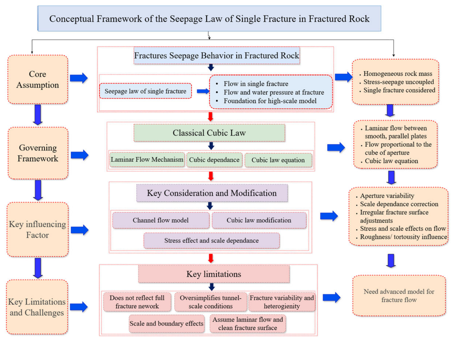
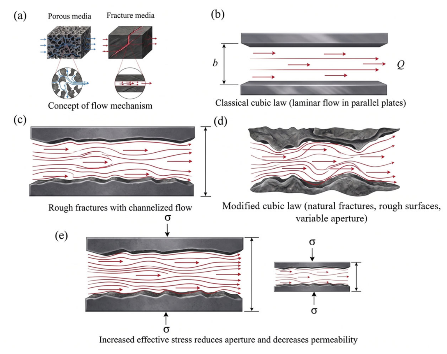
The study of seepage laws in single fractures forms the theoretical foundation for understanding groundwater flow in fractured rock masses [149]. In contrast to porous media, where flow occurs through interconnected pores, seepage in fractured rock masses is dominated by flow along discrete fracture surfaces [147]. As shown in Figure 13, fracture seepage is controlled by aperture, fracture roughness, channelized flow, and stress-dependent closure. As a result, fracture-scale seepage behavior plays a decisive role in controlling permeability, flow rate, and water pressure distribution around tunnels subjected to high groundwater pressure [153,154,155].
Systematic research on fracture seepage began in the mid-twentieth century. In 1951, a former Soviet scholar conducted experimental investigations on water flow through single fractures and derived the classical cubic law, which describes laminar flow between two smooth, parallel plates [156]. According to the cubic law, the volumetric flow rate is proportional to the cube of the fracture aperture, implying that small changes in aperture can lead to orders-of-magnitude variations in permeability. The cubic law can be expressed as Equation (3).
Q = b 3 12 μ d p d x
where Q is the flow rate per unit, b is the fracture aperture, u is the dynamic viscosity of water, and dp/dx is the hydraulic pressure gradient along the fracture. Because of its physical interpretation and mathematical simplicity, the cubic law has been widely used as a first-order approximation for fracture flow.
However, it was shown in an earlier study that the assumptions required for cubical flow law hold rarely in natural fractures. Tsang [157] observed that if the laminar parallel-plate assumption is made for flow through fractures, the flow is generally very unevenly distributed and often concentrates in preferential channels, and proposed the channel flow model in 1984. Subsequent studies confirmed that the cubic law only applies to ideal fractures characterized by smooth walls, large openings and no filling material [158].
In order to generalize the fracture seepage models, many scholars produced extensions of the cubic law. Neuzil and Tracy [159] proposed a corrective methodology based on the perpendicular aperture width to the direction of flow in conjunction with probability density functions to capture the heterogeneity of the aperture space. Tsang generalized this idea for 2D fracture surfaces, also accounting for specimen size effects, and then proposed new equations explicitly with scale dependence [160,161]. The approximate method has been developed by Elsworth & Goodman [162] using the concept of representing fracture geometry through regular curves (e.g., sine wave) and analyzing how aperture develops with compressive force and determining permeability from it. Wang et al. [163] critically assessed the applicability of fracture flow equation based on cubic laws and developed a modified local cubic law for rough and tortuous fractures. Moreover, He et al. [164] suggested a corrected cubic law for rough-walled fractures, indicating that classical cubic law prediction needs to be modified when the fractures are not smooth enough.
Alongside theoretical studies, there have also been numerous experiments on fracture and rock permeability. Kranzz, Gale, Jones, and others proposed empirical formulas for permeability coefficients of different rock types based on laboratory testing [165,166,167]. Snow investigated the influence of normal stress distribution on single-fracture seepage and established stress-dependent permeability relationships [168]. Laboratory and analytical studies have shown that fracture permeability is highly sensitive to effective normal stress, because increasing normal stress promotes fracture closure and reduces hydraulic aperture, thereby markedly decreasing seepage capacity [169,170]. Further studies under true-triaxial or multi-directional stress conditions indicate that both stress magnitude and stress orientation jointly control fracture deformation and permeability evolution, especially in anisotropic fractured rock systems [171].

Limitations

Single-fracture seepage laws are important for understanding the fundamental relationship between fracture aperture, roughness, stress state, and flow capacity [172]. Their main limitation is that they describe seepage behavior at the fracture scale and cannot be directly transferred to tunnel-scale external water pressure assessment without upscaling [14]. Natural fractured rock masses contain multiple intersecting fractures with variable apertures, rough surfaces, fillings, connectivity, and stress-dependent opening or closure. In drill-and-blast subsea tunnels, excavation disturbance and blasting damage may further modify these fracture characteristics [173,174]. Therefore, single-fracture seepage laws provide a theoretical basis for understanding fracture-controlled flow, but they must be integrated with rock-mass-scale models to evaluate water pressure acting on initial support. The overall conceptual framework of the single fracture law approach for underwater tunnel design is summarized in Figure 14.

4.2. Seepage Models for Fractured Rock Masses

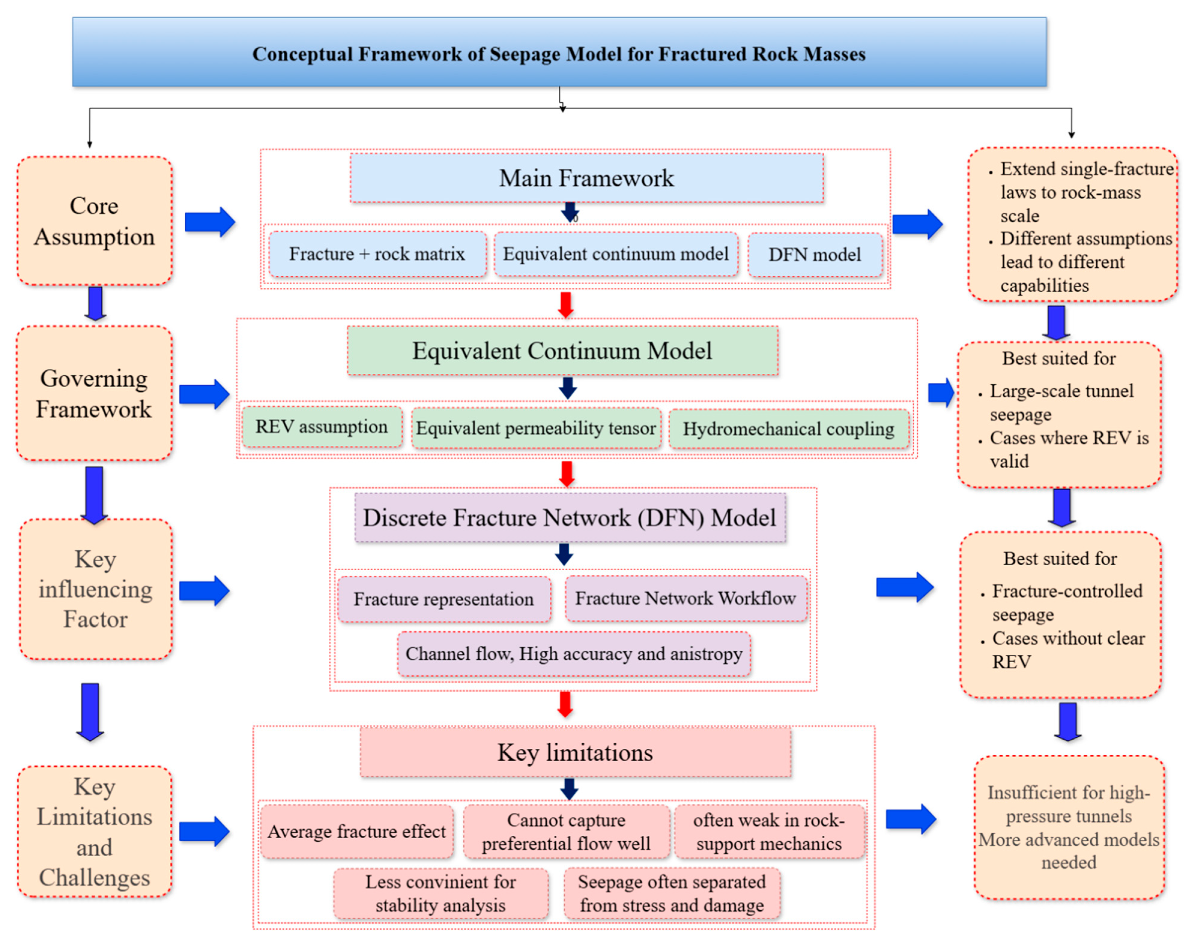
To extend single-fracture seepage behavior to engineering-scale problems, various seepage models for fractured rock masses have been developed. These models aim to represent the collective hydraulic behavior of multiple fractures and their interaction with the surrounding rock matrix [175,176]. Since the 1950s, research on seepage in fractured rock masses has gradually evolved from fracture-scale studies to rock-mass-scale modeling approaches. At present, equivalent continuum models and discrete fracture network (DFN) models are the two most widely adopted seepage modeling frameworks, each based on distinct conceptual assumptions and computational strategies [177,178].
(1)
Equivalent Continuum Models
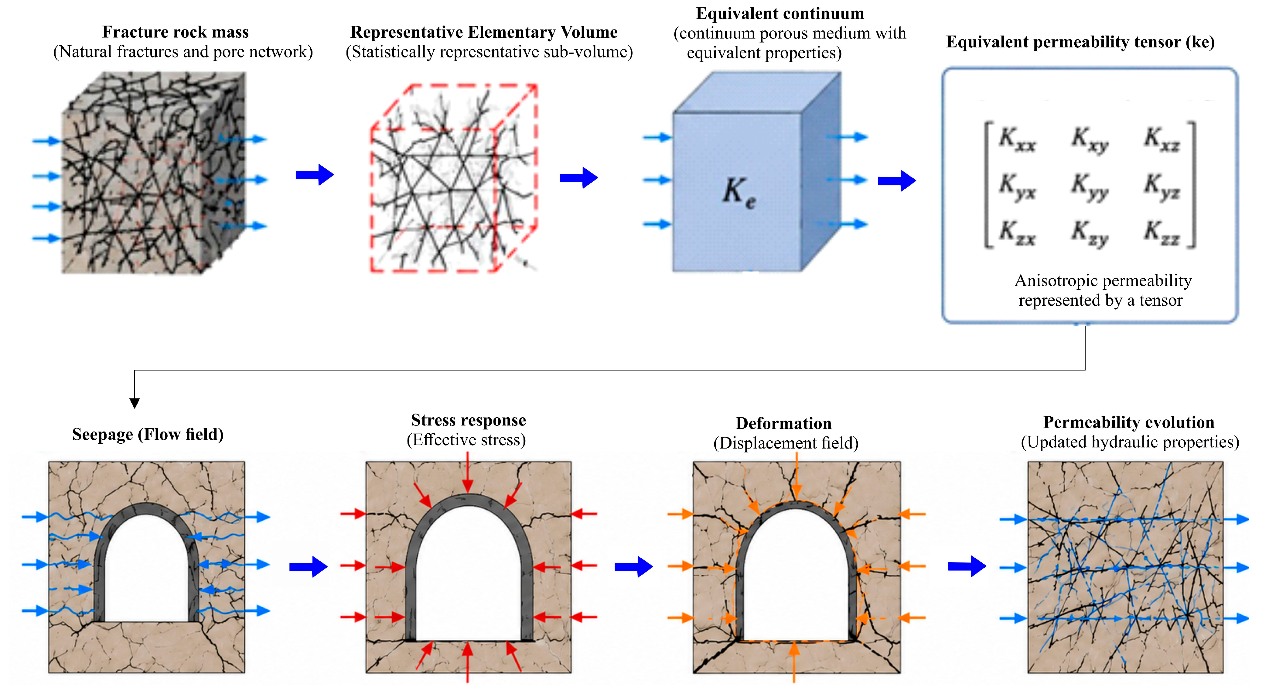
The concept of equivalent continuum theory postulates that fractured rock masses have an adequate amount of fracture systems oriented in different directions and thus, their hydraulic behavior can be considered statistically for the representative elementary volume (REV) [179,180,181]. This process of scaling from the fractured rock masses to the equivalent continuum having an equivalent permeability tensor is represented schematically in Figure 15. As per this assumption, the fractured rock masses behave as continuous porous media, and the seepage process is formulated with governing equations in the form of continuum theory. The effect of fractures is taken into account implicitly by the equivalent permeability tensors, while the water interaction between rock pore spaces and fractures is not considered [182].
Equivalent Continuum Theory was initially introduced by Snow, who conducted fractured rock seepage investigations by employing poro-elasticity and permeability tensor theory [168]. Oda, in turn, refined this methodology by statistically analyzing fracture orientation, density, and connectivity as well as by developing equivalent permeability tensors through continuum mechanics [179]. Based on the equivalent continuum theory, subsequent studies have generalized the classical seepage analysis by including hydro-mechanical coupling and demonstrated that pore pressure, stress re-distribution, and deformation must be simultaneously solved for fractured rocks. For instance, Chen et al. [183] proposed a hydro-mechanical model for fractured rock engineering and demonstrated that fluid flow has a strong impact on deformation and stability. Subsequent research has further generalized the methodology by incorporating additional physical phenomena. Tsang [184] summarized the developments in the field of thermo-hydro-mechanical (THM) coupling in fractured rocks and highlighted the necessity of considering the effects of temperature on seepage and stress. Moreover, Zhao et al. [17] have introduced the concept of a coupled seepage–damage model where the evolution of damage is directly related to changes in permeability and Shao et al. [151] developed a coupled stress–seepage–damage model that can simulate both crack formation and the hydrological response together. The above developments demonstrate that contemporary coupled models account for permeability evolution, crack generation, and multi-physical phenomena that conventional seepage models cannot capture.
Because of the simple formulation of the equivalent continuum model, as well as its computation efficiency, it has been extensively applied in the numerical analysis of tunnel seepage flow and groundwater flow, especially in cases of large size that require the calculation without the representation of the individual fractures [185]. Nevertheless, the applicability of the method depends significantly on the presence of an REV. In highly heterogeneous or poorly fractured rocks, the REV assumption may not apply, resulting in discrepancies between the calculations and reality [186]. Moreover, equivalent continuum models are generally unable to capture localized and anisotropic flow controlled by dominant fracture sets, which often govern groundwater inflow and external water pressure distribution in subsea tunnels [187].
(2)
Discrete Fracture Network Models
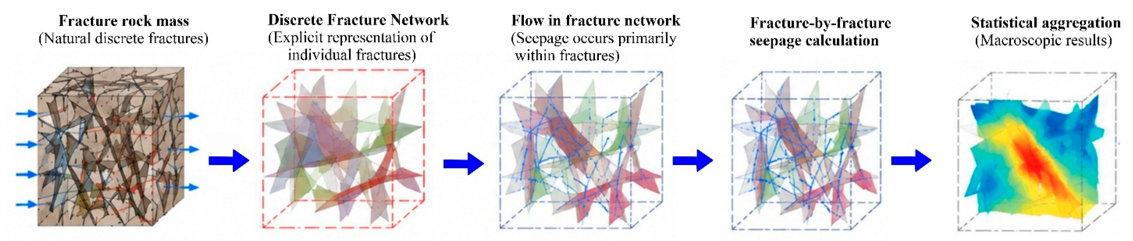
In contrast to continuum-based approaches, the discrete fracture network (DFN) model explicitly represents individual fractures and their geometric characteristics, including fracture density, length, orientation, aperture, and connectivity (Figure 16) [188,189]. In DFN models, groundwater flow is assumed to occur primarily within the fracture network, and seepage behavior is governed by fracture-scale flow laws [190]. This approach is particularly suitable for fractured rock masses in which REV conditions do not exist or are very large, and where fracture-controlled seepage dominates hydraulic behavior [191].
The fracture network concept was first proposed by Wittke in 1987 [192]. DFN modeling generally involves two main stages. In the first stage, a fracture network is generated based on geological survey data and statistical descriptions of fracture properties. During the second phase, seepage calculation is done on a fracture-by-fracture basis, with the results being subjected to statistical analysis to acquire macroscopic seepage properties [192]. In terms of computation, DFN modeling involves point-to-point calculation and can attain extremely precise results locally, thus being very efficient in the analysis of localized flows, channelized seepage, and anisotropy of permeability in fractured rock masses [193,194].
Although DFN models are more physically accurate than conventional ones, they still encounter some difficulties in applying to tunnels. In order to have an accurate representation of a DFN model, precise and accurate information about the rock geometry and its connectivity should be known; however, such information is not always easily obtained on a tunnel scale [195]. Furthermore, this type of modeling is highly dependent on input parameters and utilizes a great deal of geological information, making it uncertain to use simulation results. In addition, DFN modeling is very computationally intensive, especially when dealing with large or intensely fractured rock masses [191].

Limitations

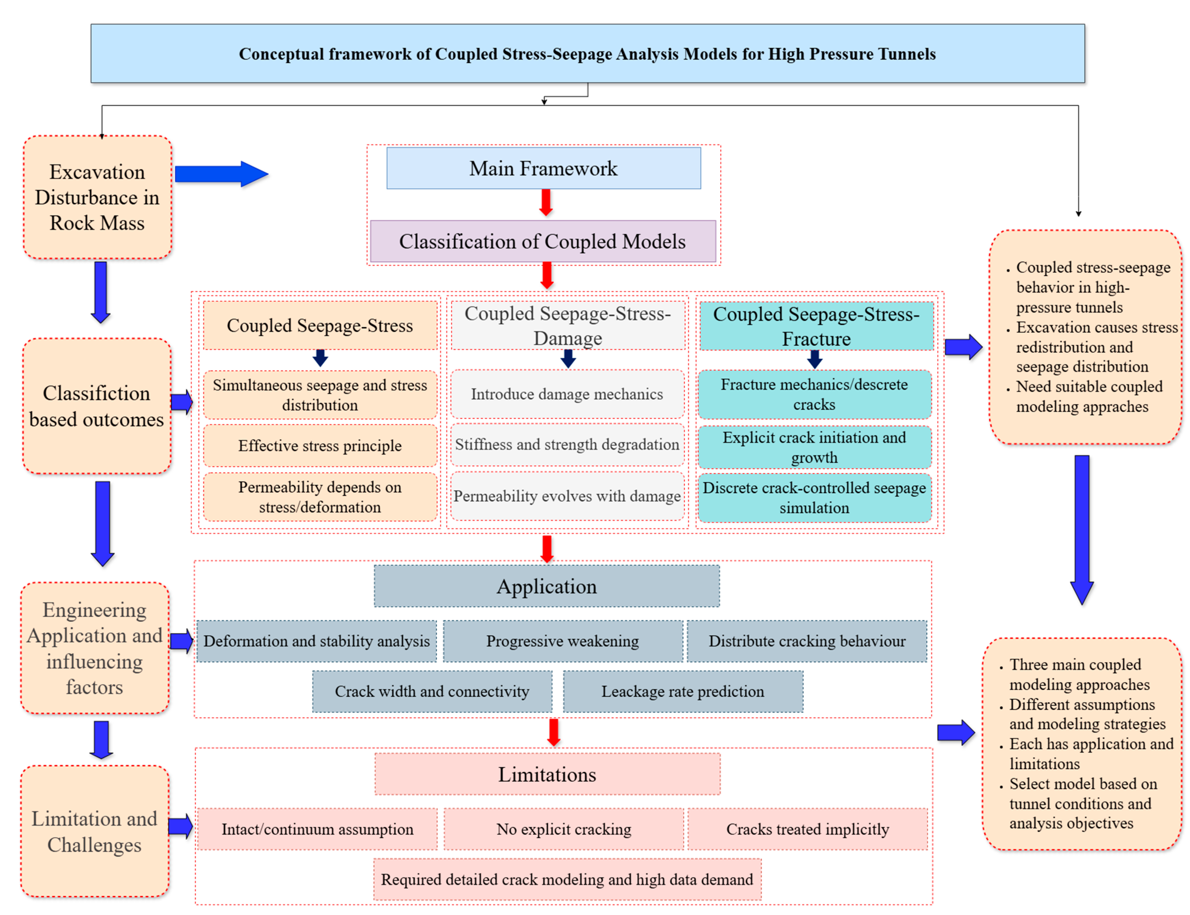
For tunnel-support water pressure assessment, both equivalent continuum and DFN models have limitations. Equivalent continuum models use averaged hydraulic properties and therefore cannot explicitly capture preferential flow or localized hydraulic responses caused by dominant fractures [196,197]. DFN models can represent localized fracture flow, but they often simplify or neglect the mechanical response of the surrounding rock and support system [147]. In many cases, seepage is still analyzed separately from stress redistribution and damage evolution, although hydraulic pressure, deformation, and fracture opening strongly interact in fractured rock masses [148]. Therefore, while these models are useful for seepage-field description, they are insufficient for reliable evaluation of external water pressure on tunnel supports under high-pressure conditions. This limitation supports the need for coupled stress–seepage–damage and stress–seepage–fracturing models, as summarized in Figure 17.

4.3. Coupled Stress–Seepage Analysis Models

Coupled stress–seepage analysis models were developed to address the intrinsic interaction between mechanical deformation and groundwater flow in rock masses subjected to excavation disturbance [151]. In tunnel engineering, seepage behavior and stress redistribution cannot be treated independently, as pore water pressure directly affects effective stress, deformation, and strength, while mechanical responses alter fracture apertures, connectivity, and permeability [148]. Consequently, coupled models provide a more realistic framework for analyzing groundwater-structure interaction in high-pressure tunnels than traditional uncoupled seepage or mechanical approaches.
Research on coupled stress–seepage analysis for high-pressure tunnels has primarily focused on the development of coupled modeling frameworks and the investigation of lining cracking behavior. Currently, coupled analysis methods employed in tunnel engineering can be broadly categorized into three types: seepage–stress coupled models, seepage–stress–damage coupled models, and seepage–stress–fracture coupled models.
The seepage–stress coupled model represents the earliest form of coupled analysis, in which groundwater flow and stress fields are solved simultaneously. In this framework, pore water pressure is incorporated into the mechanical equilibrium equations through effective stress principles, while permeability may be expressed as a function of stress or deformation [198]. This approach represents a significant improvement over traditional methods that treat seepage as an external load.
Lamas and Sousa [199] applied a hydraulically coupled finite element model to analyze seepage–stress interaction in pressure tunnels containing initial cracks between the lining and surrounding rock. Bian et al. [200] proposed a coupled seepage–stress finite-element method to simulate hydro-mechanical interaction in cracked concrete linings and surrounding rock under high water pressure, showing that seepage and stress fields should be solved together when evaluating lining behavior. Zhang et al. [201] further developed a complete hydro-mechanical numerical model for high-pressure tunnels, emphasizing that realistic analysis must incorporate saturated porous-media behavior, lining-rock interaction, and material nonlinearity. Wang et al. [202] also showed that pore water pressure and deformation in pressure tunnels are strongly interdependent, and that coupled seepage–stress analysis is necessary to predict tunnel response under groundwater loading. In addition, Wang et al. [74] presented analytical solutions for deep noncircular tunnels in saturated ground that explicitly consider hydro-mechanical coupling and liner–rock interaction. From the design perspective, Zareifard [203] proposed an analytical framework for pressure tunnels with permeable linings based on a generalized effective stress principle, showing that seepage-induced stresses in both the lining and surrounding ground must be considered in design.
Although seepage–stress coupled models have been widely applied to analyze tunnel deformation, stability, and water pressure distribution, they generally assume intact or elastoplastic material behavior and do not explicitly consider progressive damage or cracking. As a result, their applicability is limited for fractured rock masses and drill-and-blast subsea tunnels subjected to high water pressure.
(1)
Seepage–Stress–Damage Coupled Analysis Models
To overcome the limitations of seepage–stress coupling, seepage–stress–damage coupled models were developed by introducing damage mechanics into the coupled framework. In these models, damage variables are used to describe stiffness degradation and strength reduction in materials, while permeability is allowed to evolve as a function of damage, enabling simulation of progressive weakening and crack-induced permeability increase.
Han and Dusseault [204] employed a permeability evolution equation accounting for surrounding rock deformation characteristics together with an elastoplastic coupled damage constitutive model. Schulze et al. [205] and Oda et al. [206] proposed coupled models linking seepage and damage evolution in fractured rock masses. Recent studies have developed coupled stress–seepage–damage numerical models to explicitly simulate crack propagation and permeability evolution using finite element approaches, which link rock damage progression to fluid flow changes under stress [17,151,207]. For instance, ref. [17] developed a dual-medium coupled seepage–damage model capturing fracture network behavior and stress-dependent permeability changes in fractured rocks. It was further established that the damage-dependent permeability development process is equally important in controlling the mechanisms of fluid trans-port, underscoring the importance of incorporating the damage development process in the seepage process modeling [208]. Reference [148] formulated the seepage-deformation coupling model that illustrated the interactions between fluid seepage through the fracture zone and the deformation process. Additionally, ref. [209] developed a seepage–stress–damage model which combines damage evolution statistically together with the coupling of fluid mechanics. The above models offer a more realistic representation of hydro-mechanical coupling in fractured rock mass compared to the continuum-based approaches.
Seepage–stress–damage models can describe gradual damage accumulation and permeability evolution and are suitable for analyzing high-pressure tunnels where distributed cracking and stiffness degradation play an important role. However, they remain limited in their ability to explicitly represent discrete crack geometry and crack-controlled seepage.
(2)
Seepage–Stress–Fracturing Coupled Analysis Models
Engineering practice has shown that under high internal water pressure, tunnel linings tend to crack sparsely but extensively, and seepage through lining cracks may account for more than 95% of total tunnel leakage [18]. Under such conditions, coupled models based on equivalent continuum assumptions, including seepage–stress and seepage–stress–damage models, cannot accurately predict critical parameters such as crack width, crack connectivity, or leakage rates through the lining [73].
To address this issue, coupled seepage–stress–fracturing models were developed by explicitly representing crack initiation and propagation using fracture mechanics or discrete-cracking approaches. Hu et al. [210] proposed a coupled seepage–stress–fracturing analysis model based on a bonded-crack model combined with an embedded-rebar model, and applied it to stress–seepage analysis of reinforced concrete linings in high-pressure tunnels. Luo et al. [211] established a seepage–stress coupling model for fractured rock masses using XFEM and showed that fracture geometry and stress redistribution strongly influence seepage behavior and crack evolution. In addition, Jia et al. [212] proposed a nonlinear hydro-mechanical coupled numerical method for deep-buried tunnels with discrete fracture networks, showing that fracture-controlled seepage and mechanical interaction must be considered simultaneously to evaluate seepage stability under high groundwater pressure. Jin et al. [213] further developed a hydro-mechanical model for cohesive crack propagation in concrete linings under high internal water pressure, demonstrating that explicit crack propagation analysis is necessary to capture localized leakage and fracture-driven water pressure redistribution in tunnel linings. Together, these studies indicate that seepage–stress–fracture coupling provides a more realistic framework than continuum-based seepage–stress or seepage–stress–damage models when fracture growth and crack-controlled flow are dominant.
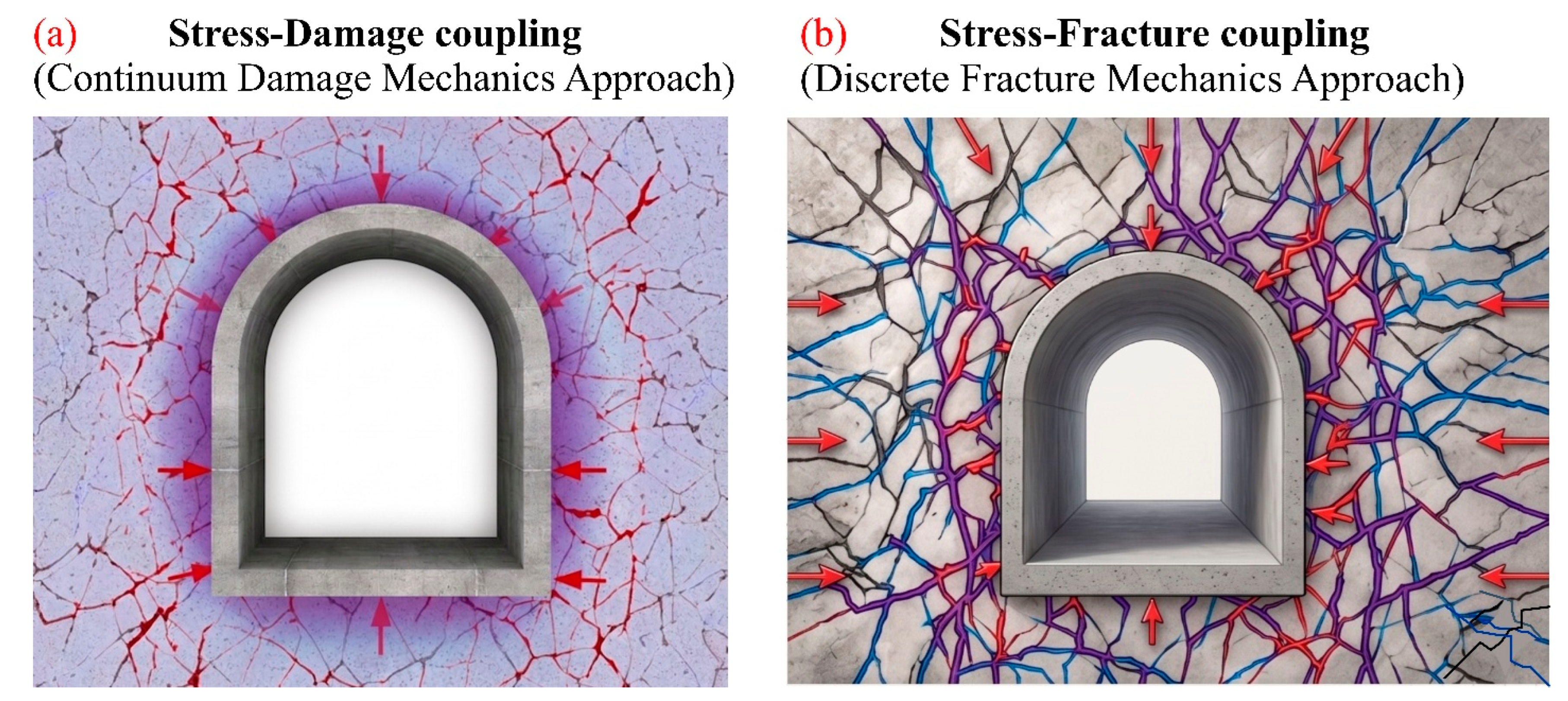
The conceptual difference between stress–damage coupling and stress–fracture coupling is illustrated in Figure 18, where stress–damage coupling represents distributed material degradation using a continuum damage mechanics approach, whereas stress–fracture coupling explicitly captures crack initiation, propagation, connectivity, and fracture-controlled seepage paths.

Limitation

Coupled stress–seepage analysis has improved understanding of high-pressure tunnel behavior, but the problem remains strongly nonlinear because of non-Darcy flow, fractured-media interaction, material degradation, and crack propagation in rock and lining systems. Recent fully coupled and DFN-based studies show that permeability evolution, fracture-network effects, and explicit crack development are essential for realistic prediction of seepage behavior and water pressure redistribution [214,215]. For example, Jia et al. [212] emphasized nonlinear seepage and fracture-network effects in deep-buried fractured tunnels, while Zhang et al. [216] incorporated permeability variation and non-Darcy flow in a fully coupled hydro-mechanical model. At the lining scale, Jin et al. [213] showed that crack propagation under high water pressure requires hydro-mechanical cohesive-fracture modeling. Therefore, despite challenges in parameter calibration, numerical stability, and computational efficiency, advanced coupled stress–seepage–damage/fracturing models remain the most physically consistent tools for analyzing external water pressure redistribution and support cracking in high-pressure subsea tunnels, as summarized in Figure 19.
In addition to qualitative comparisons of different calculation and evaluation methods, representative quantitative results reported in previous studies are summarized in Table 2. These values include external water pressure, tunnel water inflow, water pressure reduction coefficients, drainage discharge, grouting-ring parameters, lining safety factors, bending moments, deformation, and water pressure resistance. The selected studies cover subsea and underwater tunnels, reduction coefficient-based design, analytical and semi-analytical solutions, numerical simulations, physical model tests, and fractured rock seepage analyses. Although many existing studies on tunnel external water pressure originate from mountain tunnels, hydraulic tunnels, loess tunnels, coal-mine roadways, and other water-rich underground openings, their relevance to drill-and-blast subsea tunnels should be interpreted carefully. These studies provide transferable mechanistic insights into seepage redistribution, drainage-induced pressure relief, grouting effects, permeability contrast, fracture-controlled flow, and stress–seepage interaction. However, their conclusions cannot be directly applied to high-head subsea tunnels without considering the distinctive marine boundary conditions. Compared with ordinary mountain or hydraulic tunnels, drill-and-blast subsea tunnels are subjected to persistent groundwater recharge from the sea, high hydraulic head, fractured or fault-controlled rock masses, excavation-induced damage, temporary and discontinuous initial support, and imperfect support–rock contact. Therefore, evidence from non-subsea cases is used in this review mainly as mechanistic or methodological support, whereas subsea tunnel design requires recalibration through subsea-specific boundary conditions, field monitoring, laboratory validation, and coupled stress–seepage–damage analysis.

4.4. Hydro-Mechanical Discrete Lattice Models

Hydro-mechanical discrete lattice models represent another promising numerical approach for analyzing crack-controlled seepage and external water pressure evolution in fractured rock masses and cracked support materials. In lattice element models, the solid domain is idealized as an assembly of one-dimensional lattice elements, which makes the method suitable for simulating discontinuity propagation, multiple-crack interaction, and crack coalescence [225]. As schematically illustrated in Figure 20, fractured surrounding rock and cracked initial support can be transformed into a discrete lattice representation, allowing crack initiation, crack propagation, seepage through connected cracks, and subsequent pressure redistribution to be explicitly described. Compared with conventional continuum-based seepage–stress models, hydro-mechanical lattice-type formulations can more explicitly represent crack initiation, crack opening/closure, progressive damage localization, and the development of preferential seepage paths. This is particularly relevant to drill-and-blast subsea tunnels, where blasting disturbance, fractured surrounding rock, shotcrete cracking, and imperfect support–rock contact may generate localized flow channels behind the initial support under high hydraulic head. Related coupled hydro-mechanical finite-discrete formulations have shown that fracture flow can be described using the cubic law, while matrix seepage can be described using Darcy’s law, enabling simulation of fracture initiation, propagation, intersection, and fluid-pressure evolution during hydraulic fracturing [226]. Therefore, hydro-mechanical discrete lattice models may provide a useful meso-scale framework for investigating how discrete cracks and crack seepage influence external water pressure redistribution around initial support. The overall role, application scope, and limitations of hydro-mechanical discrete lattice models for crack-controlled seepage and external water pressure assessment are summarized in Figure 21. However, their direct application to full-scale drill-and-blast subsea tunnels remains limited because they require careful calibration of lattice parameters, fracture criteria, hydraulic aperture relationships, crack-flow laws, and hydraulic boundary conditions. Their computational cost may also be high for large-scale tunnel simulations. Thus, these models are currently more suitable for mechanism analysis and validation of crack-controlled seepage processes than for routine engineering design.

Limitations

Despite their advantages, hydro-mechanical discrete lattice models still have important limitations for drill-and-blast subsea tunnel applications. Their accuracy depends strongly on the calibration of lattice stiffness, element strength, fracture criteria, hydraulic aperture, and crack-flow relationships, because an inappropriate lattice discretization or element stiffness can distort the mechanical response [225]. In addition, although lattice-type models are effective for simulating brittle fracture, crack interaction, and crack coalescence, their application to coupled seepage–fracture problems at full tunnel scale remains computationally demanding. Existing hydro-mechanical finite-discrete formulations can represent matrix seepage using Darcy’s law and fracture flow using the cubic law, but they still require detailed hydraulic and mechanical parameters that are difficult to obtain for fractured subsea rock masses and cracked initial support [226,227]. Therefore, these models are currently more suitable for meso-scale mechanism analysis and validation of crack-controlled seepage processes than for routine engineering design of full-scale drill-and-blast subsea tunnels.

5. Existing Research Gaps and Key Challenges

Although substantial progress has been made in understanding seepage behavior, hydro-mechanical coupling, and water pressure control in tunnels, important limitations remain when these methods are applied to the external water pressure acting on the initial support of drill-and-blast subsea tunnels. These limitations arise not from a lack of analytical or numerical techniques, but from the difficulty of representing the combined effects of fractured rock masses, excavation disturbance, and support damage under high water pressure. In particular, recent reviews and engineering studies on drill-and-blast subsea tunnels emphasize that blasting damage, water inrush risk, leakage control, and initial-support interaction remain key unresolved issues in subsea tunnel design and construction [13,28,228].
A primary unresolved issue lies in the definition and calculation of external water pressure acting on the initial support. Existing studies and design practices still rely heavily on simplified hydraulic assumptions, drainage-based load reduction concepts, or indirect estimation methods, while unified construction and seepage-control design standards for early-stage tunnel water pressure remain lacking [13,67,229].
Another major challenge is the inadequate representation of fractured rock mass characteristics in existing water pressure calculation methods. Equivalent continuum or idealized analytical approaches often fail to capture localized seepage and pressure concentration associated with dominant fractures, fracture zones, or karst pathways. Field- and model-based studies have shown that localized water pressure in fracture zones can greatly exceed that in surrounding ground, and that fractured rock seepage stability in deep-buried tunnels is strongly influenced by non-Darcy flow and hydro-mechanical coupling [212,230,231].
The limited consideration of damage and cracking in initial support systems is another critical gap [65]. Recent studies on underwater and high-hydraulic-pressure tunnels show that blasting damage, excavation unloading, and water pressure-induced cracking can degrade support performance, alter seepage paths, and intensify leakage or support damage; however, these effects are still not consistently integrated into practical external-water pressure calculations [98,212,228,232].
In addition, hydro-mechanical coupling in fractured rock masses under high water pressure remains insufficiently addressed in tunnel-scale simulations. Coupled analyses have shown that seepage, stress redistribution, fracture opening, and water inrush are strongly interdependent, yet many practical models still do not fully represent this bidirectional interaction under construction disturbance and fracture-controlled flow conditions [212,233,234].
The lack of unified validation frameworks further limits reliability. Physical model testing and field monitoring are valuable, but recent geomechanical model studies still note the difficulty of accurately calculating early-stage water pressure and the lack of unified standards, while validation that combines physical tests, numerical models, and field observations remains limited [13,229].
Therefore, existing research has not yet fully addressed the unique conditions of drill-and-blast subsea tunnels, where fractured rock, hydro-mechanical coupling, and support damage interact in a highly complex manner. Addressing these challenges requires more advanced coupled stress–seepage–damage and stress–seepage–fracture models, supported by experimental validation and field observation, to establish reliable calculation methods for external water pressure acting on initial support under fractured surrounding-rock conditions [13,231,234].
Furthermore, a comparative summary of the main external water pressure assessment methods for drill-and-blast subsea tunnels is presented in Table 3. The table compares their basic assumptions, advantages, limitations, and suitable engineering applications, providing a clearer basis for selecting appropriate methods under different geological, hydraulic, and support conditions.

6. Future Research Direction and Development Trend

In light of the limitations and difficulties noted from the previous literature, future research into external water pressure impact on initial support under drill and blast subsea tunneling will need to concentrate on designing mechanisms that provide reliable quantitative approaches. This is especially true regarding the interactions between fractured rock seepage, stress redistribution due to tunneling, and the progressive deterioration of the surrounding rock and support structures.

6.1. Development of Unified Definitions and Load Characterization

A crucial focus for future research should be the establishment of a precise definition of external water pressure in the context of initial support. External water pressure is currently being considered in terms of either its reduced hydrostatic value or as a force equivalent to that generated by seepage action, which can lead to confusion in calculation and design practice. There is need for further clarification regarding the physical significance of the external water pressure under conditions of hydro-mechanical interaction and its distinction from the lining water pressure or groundwater head.

6.2. Advancement of Coupled Stress–Seepage–Damage and Fracturing Models

As for the key role played by crack propagation and permeability evolution under high water pressure, future studies should develop coupled models of stress–seepage–damage/fracturing and hydro-mechanical discrete lattice models even further. Studies should pay special attention to developing constitutive relations between stress, damage parameters, fracture aperture, and permeability evolution of fractured rock massifs and shotcrete reinforcement. Specifically, modeling the process of transition from damage distribution to fracture control of seepage behavior would enable one to predict more accurately how water pressure would affect the initial support.

6.3. Improved Representation of Initial Support–Rock Interaction

One key area of research would be the modeling of initial contact support-rock behavior under the action of coupled seepage and stress. In the case of drill-and-blast tunnels in subsea environments, the initial supports typically undergo partial debonding, fracturing, and loss of contact, all of which have a major effect on the flow paths and load transfer mechanism. Numerical models in future studies should take into account the evolving contact condition and permeability of the interface between support system and rock fractures.

6.4. Integration of Fracture Network Characterization and Multi-Scale Modeling

For improving the simulation of fracture-controlled seepage phenomena, future work needs to incorporate the characterization of fracture networks into the multi-scale simulation methodologies. A combination of field studies on geology, description of fractures statistically, and modeling numerically could be helpful for reliable modeling of seepages. The hybrid simulation approach which incorporates equivalent continuum modeling at the tunnel scale and discrete fracture modeling at the critical areas could be an appropriate compromise.

6.5. Experimental Validation and Field Monitoring

In order to advance the development of coupled modeling, experimental validation and field observations are needed. Experimental research in the future should be devoted to physical model testing of coupled seepage–stress–damage processes, paying particular attention to scaling laws. Simultaneously, field observation of pore water pressure, deformations, and support cracks in subsea tunnels could serve as useful information in the calibration and validation of numerical models.

6.6. Translation into Design Methods and Technical Guidelines

Lastly, future research efforts must ensure that both theoretical and numerical advances are converted into design approaches and technical guidelines. These would include the creation of simplified design equations and design charts from sophisticated coupled analyses that can be used in real life. The inclusion of mechanism-based considerations in the design code would ensure that the empirical considerations are minimized when it comes to designing subsea tunnels at high water pressures.

7. Conclusions

This review has systematically addressed the issue of external water pressure acting on the initial support of drill-and-blast subsea tunnels, focusing on fractured rock masses and hydro-mechanical coupling effects. Through the synthesis of tunnel support design concept research, calculation methods, seepage properties, and coupling simulation techniques, the strengths and weaknesses of the existing methodologies have been analyzed, and physical phenomena controlling the redistribution of water pressure at high groundwater pressure have been identified.
The conventional empirical reduction coefficient approach and analytical solutions are useful for initial evaluation and simplified cases; nevertheless, these approaches use several idealized assumptions that are hard to fulfill in the case of fractured subsea environments. The numerical analysis approach offers an important development in terms of the possibility of using complicated shapes and boundary conditions; nevertheless, the conventional approaches based on the seepage model or seepage–stress interaction are inadequate in predicting the permeability changes, crack formation, and the location of seepage channels that govern the water pressure changes.
One of the important conclusions drawn in the present paper is that the advanced coupled models of seepage–damage–stress and seepage–fracturing–stress represent the most sophisticated and physically realistic model approach for the evaluation of external water pressure in subsea tunnels. The ability of such models to account for the fracture control of seepage processes, stress redistribution, material degradation, and crack formation in the initial support makes it possible to consider the dynamic changes in water pressure. Such modeling represents a transition from simple load calculations to mechanism-based analysis necessary for high-pressure subsea tunnels.
Furthermore, hydro-mechanical discrete lattice models present an attractive complementary alternative for the evaluation of external water pressure since they allow modeling crack formation, propagation, coalescence, and permeability through crack network directly. With such models, it becomes possible to represent the rock or the support material by discrete lattice elements, which enables better modeling of crack-controlled permeability development and localized water flow paths compared to continuum models. This is highly important in drill-and-blast subsea tunnels, in which blasting effects, fractured rock, cracked shotcrete, and inadequate contact between support and rock can result in irregular distribution of water pressure.
Despite these advances, significant research gaps remain. In particular, the lack of a unified definition and calculation method for external water pressure acting on initial support, limited integration of fractured rock characteristics and support–rock interaction, and insufficient validation through combined experimental and field data continue to hinder reliable design application. Existing design codes do not yet reflect recent theoretical and numerical developments, resulting in continued reliance on empirical assumptions.
Overall, this review underscores the necessity of integrating seepage theory, fracture mechanics, damage modeling, and engineering practice to establish rational and reliable methods for calculating external water pressure on initial support. Addressing the identified challenges through advanced coupled modeling, systematic validation, and translation into practical design guidelines will be critical for improving the safety and durability of subsea tunnels constructed under high water pressure conditions.

Author Contributions

S.H.: Writing—review and editing, Writing—original draft, Visualization, Validation, Software, Project administration, Methodology, Investigation, Formal analysis, Data curation, Conceptualization. J.H.: Writing—review and editing, Validation, Methodology, Investigation, Data curation. L.C.: Writing—review and editing, Visualization, Validation, Supervision, Resources, Project administration, Funding acquisition, Data curation. S.Q.: Writing—review and editing, Supervision, Resources, Project administration, Funding acquisition, Data curation. All authors have read and agreed to the published version of the manuscript.

Funding

This work was supported by the National Natural Science Foundation of China (Grant No. U21A20159, No. 52279118) and the Youth Innovation Promotion Association of the Chinese Academy of Sciences (Grant No. 2023344).

Data Availability Statement

Some or all data, models, or codes that support the findings of this study are available from the corresponding author upon reasonable request.

Acknowledgments

We extend our gratitude to the ANSO Scholarship for Young Talents Program for supporting our research at the University of the Chinese Academy of Sciences (UCAS), China. Sartaj Hussain is an awardee of the ANSO Scholarship 2024-PhD.

Conflicts of Interest

The authors declare that there are no conflicts of interest regarding the publication of this manuscript. No financial, personal, or professional relationships exist that could be perceived as influencing the content of the manuscript.

References

  1. Sun, P.; Yu, Q.; You, K. Intelligent traffic management strategy for traffic congestion in underground loop. Tunn. Undergr. Space Technol. 2024, 143, 105509. [Google Scholar]
  2. Yan, Q.; Cui, L.; Dong, Y.; Sheng, Q.; Xie, B. A numerical solution of coupling hydro-mechanical behavior for subsea tunnels in strain-softening rock masses: Theory and case study. Eur. J. Environ. Civ. Eng. 2025, 30, 1–28. [Google Scholar]
  3. Hussain, S.; Cui, L.; Qian, S.; Luo, S.; He, M.; Hussain, J. Influence of lining thickness and isolation layer on tunnel stability in soft rock: Insights from large-scale model tests. Eng. Fail. Anal. 2026, 192, 110814. [Google Scholar] [CrossRef]
  4. Sheng, D.; Tan, F.; Zhang, Y.; Zhu, H.; Zuo, C.; Lv, J. Safety risk assessment of weak tunnel construction with rich groundwater using an improved weighting cloud model. Sci. Rep. 2025, 15, 16036. [Google Scholar] [CrossRef] [PubMed]
  5. Li, S.; Wang, K.; Li, L.; Zhou, Z.; Shi, S.; Liu, S. Mechanical mechanism and development trend of water-inrush disasters in karst tunnels. Chin. J. Theor. Appl. Mech. 2017, 49, 22–30. [Google Scholar]
  6. Qing, L.; Hao, L. Analysis of Water Seepage Mechanism and Study on Mechanical Properties of Highway Tunnel Based on Fluid-Structure Coupling. Eur. J. Comput. Mech. 2024, 33, 121–144. [Google Scholar] [CrossRef]
  7. Salunkhe, P.R.; Mishra, S.; Verma, S. Factors Influencing Underwater Tunnel Construction: A Detailed Review. In Proceedings of the Indian Geotechnical Conference; Spinger: Singapore, 2024; pp. 303–317. [Google Scholar]
  8. Frenelus, W.; Peng, H.; Zhang, J. Long-term degradation, damage and fracture in deep rock tunnels: A review on the effect of excavation methods. Fract. Struct. Integr. 2021, 15, 128–150. [Google Scholar] [CrossRef]
  9. Jiang, M.; Liang, Y.; Xiao, K.; Feng, W.; Ma, J.; Ren, T.; Wang, E.; Jian, Z.; Peng, C. Failure control of large-scale exposed tunnels under the combined effects of excavation damage and dynamic disturbance at a depth of 1240 m. Sci. Rep. 2025, 15, 13307. [Google Scholar] [CrossRef] [PubMed]
  10. Niu, F.; Cai, Y.; Liao, H.; Li, J.; Tang, K.; Wang, Q.; Wang, Z.; Liu, D.; Liu, T.; Liu, C. Unfavorable geology and mitigation measures for water inrush hazard during subsea tunnel construction: A global review. Water 2022, 14, 1592. [Google Scholar] [CrossRef]
  11. Yue, L.; Li, W.; Liu, Y.; Li, S.; Wang, J. A review of mechanical deformation and seepage mechanism of rock with filled joints. Deep Undergr. Sci. Eng. 2024, 3, 439–466. [Google Scholar] [CrossRef]
  12. Shaghaghi, T.; Ghadrdan, M.; Tolooiyan, A. Effect of rock mass permeability and rock fracture leak-off coefficient on the pore water pressure distribution in a fractured slope. Simul. Model. Pract. Theory 2020, 105, 102167. [Google Scholar] [CrossRef]
  13. Wang, P.; Zhang, Q.; Duan, K.; Lin, H. Geo-mechanical model test on synergistic seepage control in a deeply buried water diversion tunnel under hydro-mechanical coupling conditions. Tunn. Undergr. Space Technol. 2025, 159, 106516. [Google Scholar]
  14. Zhao, C.; Zhang, Z.; Lei, Q. Role of hydro-mechanical coupling in excavation-induced damage propagation, fracture deformation and microseismicity evolution in naturally fractured rocks. Eng. Geol. 2021, 289, 106169. [Google Scholar]
  15. Zhou, Z.-Q.; Li, L.-P.; Shi, S.-S.; Liu, C.; Gao, C.-L.; Tu, W.-F.; Wang, M.-X. Study on tunnel water inrush mechanism and simulation of seepage failure process. Rock Soil Mech. 2021, 41, 6. [Google Scholar]
  16. Dai, C.; Long, Y.; Lv, Y.; Hou, W.; Sui, H. Water inrush mechanism and safety control in drilling and blasting construction of subsea tunnel. J. Coast. Res. 2019, 94, 218–222. [Google Scholar] [CrossRef]
  17. Zhao, Y.; Liu, Q.; Zhang, C.; Liao, J.; Lin, H.; Wang, Y. Coupled seepage-damage effect in fractured rock masses: Model development and a case study. Int. J. Rock Mech. Min. Sci. 2021, 144, 104822. [Google Scholar] [CrossRef]
  18. Fan, H.; Zhu, Z.; Song, Y.; Zhang, S.; Zhu, Y.; Gao, X.; Hu, Z.; Guo, J.; Han, Z. Water pressure evolution and structural failure characteristics of tunnel lining under hydrodynamic pressure. Eng. Fail. Anal. 2021, 130, 105747. [Google Scholar] [CrossRef]
  19. Lee, I.-M.; Nam, S.-W. The study of seepage forces acting on the tunnel lining and tunnel face in shallow tunnels. Tunn. Undergr. Space Technol. 2001, 16, 31–40. [Google Scholar] [CrossRef]
  20. Chen, Z.; Li, Z.; He, C.; Ma, C.; Li, X.; Chen, K.; Zhang, H.; Liu, M. Investigation on seepage field distribution and structural safety performance of small interval tunnel in water-rich region. Tunn. Undergr. Space Technol. 2023, 138, 105172. [Google Scholar] [CrossRef]
  21. Yu, J.; Li, D.; Zheng, J.; Zhang, Z.; He, Z.; Fan, Y. Analytical study on the seepage field of different drainage and pressure relief options for tunnels in high water-rich areas. Tunn. Undergr. Space Technol. 2023, 134, 105018. [Google Scholar] [CrossRef]
  22. He, B.-G.; Zhang, Y.; Zhang, Z.-Q.; Feng, X.-T.; Sun, Z.-J. Model test on the behavior of tunnel linings under earth pressure conditions and external water pressure. Transp. Geotech. 2021, 26, 100457. [Google Scholar] [CrossRef]
  23. Zhang, Y.; Zhang, J.; Wang, C.; Ren, X. An integrated framework for improving the efficiency and safety of hydraulic tunnel construction. Tunn. Undergr. Space Technol. 2023, 131, 104836. [Google Scholar]
  24. Chen, Y.; Lin, P.; Zhu, G.; Xiang, Y.; Wang, Z.; Mou, R.; Deng, Z.; Xie, H.; Cai, M.; Wang, H. Key technologies for intelligent construction and smart operation and maintenance of large-scale hydraulic tunnels. J. Intell. Constr. 2025, 3, 1–19. [Google Scholar] [CrossRef]
  25. Ding, Y.; Zhang, X.; Zhang, B. Preliminary study on double lining support design for water plugging of highway tunnel under high water pressure in mountain area based on limited drainage. Appl. Sci. 2022, 12, 7905. [Google Scholar] [CrossRef]
  26. Bilgin, N.; Balci, C. A Review of the Conventional Tunneling Methods. In Critical Issues in Selecting Conventional and Mechanized Tunnelling Methods; Springer: Cham, Switzerlands, 2025; pp. 47–91. [Google Scholar]
  27. Cui, L.; Luo, S.; Xiao, M.; Sheng, Q.; Zheng, J.; Xu, C.; Xie, B. Bearing capacity of composite tunnel lining in soft rocks: Large-scale model test. J. Rock Mech. Geotech. Eng. 2026, 18, 2757–2775. [Google Scholar] [CrossRef]
  28. Sun, Z.; Zhang, D.; Fang, Q. Technologies for large cross-section subsea tunnel construction using drilling and blasting method. Tunn. Undergr. Space Technol. 2023, 141, 105161. [Google Scholar] [CrossRef]
  29. Zhao, J.; Tan, Z.; Ma, N. Development and application of a new reduction coefficient of water pressure on sub-sea tunnel lining. Appl. Sci. 2022, 12, 2496. [Google Scholar] [CrossRef]
  30. Peng, S.; Zhu, C.; Li, Y.; Zhanbo, L.; Yuan, L.; Yu, W.; Zhiqiang, Z.; Qiqiang, Y.; Shi, W. Reduction coefficient of external water pressure of hydraulic tunnel lining in water-rich loess stratum: Numerical and in situ test analysis. Phys. Fluids 2025, 37, 087120. [Google Scholar] [CrossRef]
  31. Liu, S.; Sun, W.; Zhang, W.; Wang, Y.; Liu, Z.; Li, Z.; Yang, Y.; He, Q.; Wu, Z.; Xiao, P. Investigation on parameters affecting reduction coefficient of groundwater buoyancy in clay layers. J. Hydrol. 2024, 638, 131560. [Google Scholar] [CrossRef]
  32. Qiu, D.; Cui, J.; Xue, Y.; Liu, Y.; Fu, K. Dynamic Risk Assessment of the Subsea Tunnel Construction Process: Analytical Model. J. Mar. Environ. Eng. 2019, 10, 195. [Google Scholar]
  33. Xue, Y.; Li, Z.; Li, S.; Qiu, D.; Su, M.; Xu, Z.; Zhou, B.; Tao, Y. Water inrush risk assessment for an undersea tunnel crossing a fault: An analytical model. Mar. Georesources Geotechnol. 2019, 37, 816–827. [Google Scholar]
  34. Xue, Y.; Li, G.; Wang, X.; Yang, W.; Qiu, D.; Su, M. Analysis and optimization design of submarine tunnels crossing fault fracture zones based on numerical simulation. Mar. Georesources Geotechnol. 2020, 38, 1106–1117. [Google Scholar]
  35. Bai, L.; Yu, G.; Geng, H. Numerical Simulation Study on the Influencing Factors of Water Inflow in Subsea Tunnels. Appl. Sci. 2026, 16, 774. [Google Scholar] [CrossRef]
  36. Zhou, L.; Yang, X.; Liu, Y.; Zhou, J.; Ge, Z. Experimental and numerical study on the mechanical properties and failure behavior of composite double-layer lining in subsea shield tunnel. Eng. Fail. Anal. 2026, 191, 110766. [Google Scholar] [CrossRef]
  37. Liu, Y.-K.; Wu, Y.; Li, W.-H.; Zhang, Q.-S.; Liu, R.T.; Bai, J.-W.; Li, W. Development of a water leakage model test system and investigation of the water leakage behavior in subsea shield tunnels during operation. Measurement 2024, 233, 114691. [Google Scholar] [CrossRef]
  38. Li, S.-C.; Liu, H.-L.; Li, L.-P.; Zhang, Q.-Q.; Wang, K.; Wang, K. Large scale three-dimensional seepage analysis model test and numerical simulation research on undersea tunnel. Appl. Ocean Res. 2016, 59, 510–520. [Google Scholar] [CrossRef]
  39. Khan, M.; Anwar, M.S.; Muhammad, T.; Saidani, T. Coupled seepage stress analysis and design optimization of deep buried subsea tunnels. Ocean Eng. 2026, 352, 124576. [Google Scholar] [CrossRef]
  40. Jiang, A.; Zheng, S.; Wang, S. Stress-seepage-damage coupling modelling method for tunnel in rich water region. Eng. Comput. 2020, 37, 2659–2683. [Google Scholar]
  41. Chen, X.; Li, Y.; Chen, H.; Fei, Y.; Yue, Q.; Li, Y.; Xiong, G.; Yu, G. CFD–DEM Modeling of Stress–Damage–Seepage Coupling Mechanisms and Support Strategies in Subsea Tunnel Excavation. Eng 2026, 7, 144. [Google Scholar]
  42. Liu, Z.-J.; Huang, Y.; Zhou, D.; Ge, H. Analysis of external water pressure for a tunnel in fractured rocks. Geofluids 2017, 2017, 8618613. [Google Scholar] [CrossRef]
  43. Huang, Y.; Fu, Z.; Chen, J.; Zhou, Z.; Wang, J. The external water pressure on a deep buried tunnel in fractured rock. Tunn. Undergr. Space Technol. 2015, 48, 58–66. [Google Scholar] [CrossRef]
  44. Yu, Y.; Jin, B. Research on Seepage Field and Stress Field of Deep-Buried Subsea Tunnel with Anisotropic Permeability of the Surrounding Rock. J. Mar. Sci. Eng. 2025, 13, 825. [Google Scholar] [CrossRef]
  45. Cao, W.; Lei, Q.; Cai, W. Stress-dependent deformation and permeability of a fractured coal subject to excavation-related loading paths. Rock Mech. Rock Eng. 2021, 54, 4299–4320. [Google Scholar]
  46. Fang, Q.; Song, H.; Zhang, D. Complex variable analysis for stress distribution of an underwater tunnel in an elastic half plane. Int. J. Numer. Anal. Methods Geomech. 2015, 39, 1821–1835. [Google Scholar] [CrossRef]
  47. Zhang, Y.; Zhang, D.; Fang, Q.; Xiong, L.; Yu, L.; Zhou, M. Analytical solutions of non-Darcy seepage of grouted subsea tunnels. Tunn. Undergr. Space Technol. 2020, 96, 103182. [Google Scholar] [CrossRef]
  48. Chen, B.; Gong, B.; Wang, S.; Tang, C.A. Research on zonal disintegration characteristics and failure mechanisms of deep tunnel in jointed rock mass with strength reduction method. Mathematics 2022, 10, 922. [Google Scholar] [CrossRef]
  49. Zhang, Q.; Zhang, X.; Wang, Z.; Xiang, W.; Xue, J. Failure mechanism and numerical simulation of zonal disintegration around a deep tunnel under high stress. Int. J. Rock Mech. Min. Sci. 2017, 93, 344–355. [Google Scholar] [CrossRef]
  50. Lu, Y.; He, B.-G.; Li, Q.; Li, H.-P. Numerical Investigation of the Cumulative Damage Effects and Safety Criterion of Deep Tunnels in a Layered Rock Mass Under Full-Face Blasting. Rock Mech. Rock Eng. 2025, 59, 2063–2087. [Google Scholar] [CrossRef]
  51. Roy, J. Spalling and Strainbursting in Deep Mining Tunnels: Data Driven and Numerical Analyses to Improve Ground Support Design and Tunnel Reliability. Ph.D. Thesis, University of British Columbia, Vancouver, BC, Canada, 2025. [Google Scholar]
  52. Yoo, C. Effect of water leakage in tunnel lining on structural performance of lining in subsea tunnels. Mar. Georesources Geotechnol. 2017, 35, 305–317. [Google Scholar]
  53. Wang, R.; Wang, X.; Zhang, W.; Xu, W.; Lu, J.; Xiang, T. Physical model experiment of external water pressure in lining surrounding rock of a deep tunnel with cross faults. J. Tsinghua Univ. (Sci. Technol.) 2024, 64, 1179–1192. [Google Scholar]
  54. Li, L.; Zhang, Z.; Nie, C.; Hu, X.; Li, Z.; Cheng, L.; Zhang, W. Research on the influence of curtain grouting parameters on the stability of tunnel surrounding rock and lining structure under the action of local high water pressure. AIP Adv. 2025, 15, 015314. [Google Scholar] [CrossRef]
  55. Qian, W.; Wang, B.; Luo, D.; Xu, A.; Li, S. Experimental investigation and application on mechanical properties of tunnel linings under different blockage rates of drainage system in a karst tunnel. Tunn. Undergr. Space Technol. 2025, 157, 106359. [Google Scholar] [CrossRef]
  56. Huang, M.; Huang, M.; Yang, Z. Large-scale model test on water pressure resistance of lining structure of water-rich tunnel. Materials 2023, 16, 440. [Google Scholar] [PubMed]
  57. Taron, J. Geophysical and Geochemical Analyses of Flow and Deformation in Fractured Rock; The Pennsylvania State University: University Park, PA, USA, 2009. [Google Scholar]
  58. Al Balushi, F. Particle-Scale Simulations for Geothermal Energy Applications. Ph.D. Thesis, Pennsylvania State University, University Park, PA, USA, 2023. [Google Scholar]
  59. Zhang, J.; Standifird, W.; Roegiers, J.-C.; Zhang, Y. Stress-dependent fluid flow and permeability in fractured media: From lab experiments to engineering applications. Rock Mech. Rock Eng. 2007, 40, 3–21. [Google Scholar]
  60. Luo, S.; Zhao, Z.; Peng, H.; Pu, H. The role of fracture surface roughness in macroscopic fluid flow and heat transfer in fractured rocks. Int. J. Rock Mech. Min. Sci. 2016, 87, 29–38. [Google Scholar] [CrossRef]
  61. Suri, Y.; Hossain, M. Numerical Simulation of Fluid Flow, Proppant Transport and Fracture Propagation in Hydraulic Fractures for Unconventional Reservoirs; Robert Gordon University: Aberdeen, UK, 2020. [Google Scholar]
  62. Lichtner, P.C. Critique of Dual Continuum Formulations of Multicomponent Reactive Transport in Fractured Porous Media; Los Alamos National Lab.: Los Alamos, NM, USA, 2000. [Google Scholar]
  63. Guo, L.; Hu, X.; Wu, L.; Li, X.; Ma, H. Simulation of fluid flow in fractured rocks based on the discrete fracture network model optimized by measured information. Int. J. Geomech. 2018, 18, 05018008. [Google Scholar] [CrossRef]
  64. Viswanathan, H.S.; Ajo-Franklin, J.; Birkholzer, J.T.; Carey, J.W.; Guglielmi, Y.; Hyman, J.; Karra, S.; Pyrak-Nolte, L.; Rajaram, H.; Srinivasan, G. From fluid flow to coupled processes in fractured rock: Recent advances and new frontiers. Rev. Geophys. 2022, 60, e2021RG000744. [Google Scholar] [CrossRef]
  65. Cui, L.; Sheng, Q.; Zheng, J.; Xie, M.; Liu, Y. A Unified Deterioration Model for Elastic Modulus of Rocks with Coupling Influence of Plastic Shear Strain and Confining Stress. Rock Mech. Rock Eng. 2022, 55, 7409–7420. [Google Scholar] [CrossRef]
  66. Ivars, D.M. Water inflow into excavations in fractured rock—A three-dimensional hydro-mechanical numerical study. Int. J. Rock Mech. Min. Sci. 2006, 43, 705–725. [Google Scholar]
  67. Wang, X.; Wang, M.; Zhang, M.; Ming, H. Theoretical and experimental study of external water pressure on tunnel lining in controlled drainage under high water level. Tunn. Undergr. Space Technol. 2008, 23, 552–560. [Google Scholar] [CrossRef]
  68. Chen, Q.; Liang, L.; Zou, B.; Xu, C.; Kong, B.; Ma, J. Analytical solutions of steady a seepage field for deep-buried tunnel with grouting ring considering anisotropic flow. J. Mar. Sci. Eng. 2022, 10, 1861. [Google Scholar] [CrossRef]
  69. SL 279-2016; Specification for Design of Hydraulic Tunnel. China Water & Power Press: Beijing, China, 2017.
  70. Zhu, C. Reduction Coefficient of External Water Pressure of Hydraulic Tunnel Lining in Saturated Q2 Loess Stratum. SSRN 2024. [Google Scholar] [CrossRef]
  71. Xu, Z.; Wang, X.; Li, S.; Gao, B.; Shi, S.; Xu, X. Parameter optimization for the thickness and hydraulic conductivity of tunnel lining and grouting rings. KSCE J. Civ. Eng. 2019, 23, 2772–2783. [Google Scholar] [CrossRef]
  72. Tamrazyan, A.; Kabantsev, O.; Matseevich, T.; Chernik, V. Estimation of the Reduction Coefficient When Calculating the Seismic Resistance of a Reinforced Concrete Frame Building after a Fire. Buildings 2024, 14, 2421. [Google Scholar] [CrossRef]
  73. Li, Z.; Zhou, Z. Numerical simulation of rock fracture and permeability characteristics under stress–seepage–damage coupling action. Int. J. Geomech. 2023, 23, 04022257. [Google Scholar]
  74. Wang, E.; Wang, H.; Song, F.; Jia, X. Analytical solutions for lined noncircular tunnels in deep ground considering hydromechanical coupling. Geomech. Geophys. Geo-Energy Geo-Resour. 2024, 10, 197. [Google Scholar] [CrossRef]
  75. Farhadian, H.; Nikvar-Hassani, A. Water flow into tunnels in discontinuous rock: A short critical review of the analytical solution of the art. Bull. Eng. Geol. Environ. 2019, 78, 3833–3849. [Google Scholar]
  76. Ng, C.; Liu, H.; Feng, S. Analytical solutions for calculating pore-water pressure in an infinite unsaturated slope with different root architectures. Can. Geotech. J. 2015, 52, 1981–1992. [Google Scholar] [CrossRef]
  77. Yu, J.; Zhang, C.; Li, D. An Analytical Solution for the Steady Seepage of Localized Line Leakage in Tunnels. Mathematics 2024, 13, 82. [Google Scholar] [CrossRef]
  78. Wang, F.; Li, P. An analytical model of seepage field for symmetrical underwater tunnels. Symmetry 2018, 10, 273. [Google Scholar] [CrossRef]
  79. Ma, W.; Song, Y.; Zhang, S.; Gu, D.; Zhang, J. Analytical study of the bolts-grouting reinforcement in cylindrical lined tunnels considering seepage. Rock Mech. Rock Eng. 2023, 56, 1489–1516. [Google Scholar]
  80. Yu, J.; Zhang, Y.; Li, D.; Zheng, J.; Zhang, W. Analytical study of steady state seepage field in tunnels with localized water leakage under the effect of grouting circle. Tunn. Undergr. Space Technol. 2024, 150, 105854. [Google Scholar] [CrossRef]
  81. Li, Z.; Liu, H.; Dun, Z.; Ren, L.; Fang, J. Grouting effect on rock fracture using shear and seepage assessment. Constr. Build. Mater. 2020, 242, 118131. [Google Scholar] [CrossRef]
  82. Bobet, A. Analytical solutions for shallow tunnels in saturated ground. J. Eng. Mech. 2001, 127, 1258–1266. [Google Scholar] [CrossRef]
  83. Nam, S.-W.; Bobet, A. Liner stresses in deep tunnels below the water table. Tunn. Undergr. Space Technol. 2006, 21, 626–635. [Google Scholar] [CrossRef]
  84. Jiang, Q.-W.; Chen, Z.-J.; Lu, J.-K.; Wang, H.-J.; Lai, P.-A. Analytical Solutions for Integrated 2D Circumferential and 3D Face Seepage in Tunnels with Excavation-Induced Damage. Geotech. Geol. Eng. 2026, 44, 215. [Google Scholar] [CrossRef]
  85. Liu, Z.; Dong, S.; Zheng, S.; Shi, Z. Research on advanced grouting curtain technology for water interception and control at the source of aquifer in coal seam roof. Sci. Rep. 2025, 15, 20354. [Google Scholar] [CrossRef] [PubMed]
  86. El Tani, M. Circular tunnel in a semi-infinite aquifer. Tunn. Undergr. Space Technol. 2003, 18, 49–55. [Google Scholar] [CrossRef]
  87. Goodman, R.E.; Moye, D.G.; Van Schalkwyk, A.; Javandel, I. Ground Water Inflows During Tunnel Driving; College of Engineering, University of California: Oakland, CA, USA, 1964. [Google Scholar]
  88. Wang, J. Once more on hydraulic pressure upon lining. Mod. Tunn. Technol. 2003, 3, 5–8. [Google Scholar]
  89. Jiang, Q.; Tang, Y. A general approximate method for the groundwater response problem caused by water level variation. J. Hydrol. 2015, 529, 398–409. [Google Scholar] [CrossRef]
  90. Tang, Y.; Jiang, Q.; Zhou, C. Approximate analytical solution to the Boussinesq equation with a sloping water-land boundary. Water Resour. Res. 2016, 52, 2529–2550. [Google Scholar]
  91. Tang, Y.; Jiang, Q. Analytical solution for the evolution of exit point along the sloping seepage face. Math. Methods Appl. Sci. 2019, 42, 6537–6554. [Google Scholar] [CrossRef]
  92. Liang, X.; Zhang, Y.-K. A new analytical method for groundwater recharge and discharge estimation. J. Hydrol. 2012, 450, 17–24. [Google Scholar] [CrossRef]
  93. Berre, I.; Doster, F.; Keilegavlen, E. Flow in fractured porous media: A review of conceptual models and discretization approaches. Transp. Porous Media 2019, 130, 215–236. [Google Scholar]
  94. Wang, E.; Wang, H.; Jia, X. New analytical solutions for stress and displacement in deeply buried noncircular tunnels incorporating the influence of seepage flow. Appl. Math. Model. 2025, 142, 115990. [Google Scholar] [CrossRef]
  95. Shen, J.; Ma, H.; Du, H.; Xin, Y.; Liu, H.; Ma, W. Numerical Simulation of the External Water Pressure in Seepage Anisotropy Under Heterogeneous Conditions. Water 2024, 16, 3173. [Google Scholar] [CrossRef]
  96. Fahimifar, A.; Zareifard, M.R. A theoretical solution for analysis of tunnels below groundwater considering the hydraulic–mechanical coupling. Tunn. Undergr. Space Technol. 2009, 24, 634–646. [Google Scholar] [CrossRef]
  97. Zareifard, M.R.; Shekari, M.R. Comprehensive solutions for underwater tunnels in rock masses with different GSI values considering blast-induced damage zone and seepage forces. Appl. Math. Model. 2021, 96, 236–268. [Google Scholar] [CrossRef]
  98. Zhang, Y.; Tan, F.; Liu, R.; Zhu, H.; Wang, X.; Jiao, Y. Water pressure relief treatment for protecting the initial support of inclined shafts at high water pressures. J. Rock Mech. Geotech. Eng. 2025, 17, 6468–6481. [Google Scholar] [CrossRef]
  99. Wang, X.; Liu, X.; Wang, E.; Liu, S.; Shan, T.; Labuz, J.F. Microcracking characterization in tensile failure of hard coal: An experimental and numerical approach. Rock Mech. Rock Eng. 2024, 57, 6441–6460. [Google Scholar] [CrossRef]
  100. Hassani, A.N.; Farhadian, H.; Katibeh, H. A comparative study on evaluation of steady-state groundwater inflow into a circular shallow tunnel. Tunn. Undergr. Space Technol. 2018, 73, 15–25. [Google Scholar] [CrossRef]
  101. Sun, S.; Jiang, Z.; Li, L.; Wei, Y. Impact characteristics of shield disc cutters under composite strata: Insights from full-scale cutting tests and theoretical studies. Tunn. Undergr. Space Technol. 2026, 174, 107692. [Google Scholar] [CrossRef]
  102. Le, C.V.; Nguyen, P.H.; Askes, H.; Pham, D. A computational homogenization approach for limit analysis of heterogeneous materials. Int. J. Numer. Methods Eng. 2017, 112, 1381–1401. [Google Scholar] [CrossRef]
  103. Lan, C.; Hongming, Z.; Qian, S.; Youkou, D.; Leyang, F. Improved experimental and numerical study on mix proportions of similar material for simulating soft rock mass. Case Stud. Constr. Mater. 2026, 24, e05917. [Google Scholar] [CrossRef]
  104. Hammah, R.; Yacoub, T.; Corkum, B.; Curran, J. The practical modelling of discontinuous rock masses with finite element analysis. In Proceedings of the ARMA US Rock Mechanics/Geomechanics Symposium, San Francisco, CA, USA, 29 June–2 July 2008. ARMA–08-180. [Google Scholar]
  105. Song, F.; Rodriguez-Dono, A.; Olivella, S.; Gens, A. Coupled solid-fluid response of deep tunnels excavated in saturated rock masses with a time-dependent plastic behaviour. Appl. Math. Model. 2021, 100, 508–535. [Google Scholar]
  106. Talmon, A.; Bezuijen, A. Simulating the consolidation of TBM grout at Noordplaspolder. Tunn. Undergr. Space Technol. 2009, 24, 493–499. [Google Scholar] [CrossRef]
  107. Zhao, C.; Lavasan, A.A.; Barciaga, T.; Kämper, C.; Mark, P.; Schanz, T. Prediction of tunnel lining forces and deformations using analytical and numerical solutions. Tunn. Undergr. Space Technol. 2017, 64, 164–176. [Google Scholar] [CrossRef]
  108. Liu, B.; Li, J.; Liu, Q.; Liu, X. Analysis of damage and permeability evolution for mudstone material under coupled stress-seepage. Materials 2020, 13, 3755. [Google Scholar] [CrossRef] [PubMed]
  109. Zhang, B.; Wang, L.; Liu, J. Finite element analysis and prediction of rock mass permeability based on a two-dimensional plane discrete fracture model. Processes 2023, 11, 1962. [Google Scholar] [CrossRef]
  110. Han, X.; Li, W. Numerical analysis on the structure type and mechanical response of tunnel crossing active reverse fault. Geofluids 2021, 2021, 5513042. [Google Scholar] [CrossRef]
  111. Shin, J.; Potts, D.; Zdravkovic, L. The effect of pore-water pressure on NATM tunnel linings in decomposed granite soil. Can. Geotech. J. 2005, 42, 1585–1599. [Google Scholar] [CrossRef]
  112. Arjnoi, P.; Jeong, J.-H.; Kim, C.-Y.; Park, K.-H. Effect of drainage conditions on porewater pressure distributions and lining stresses in drained tunnels. Tunn. Undergr. Space Technol. 2009, 24, 376–389. [Google Scholar] [CrossRef]
  113. De, A.; Niemiec, A.; Zimmie, T.F. Physical and numerical modeling to study effects of an underwater explosion on a buried tunnel. J. Geotech. Geoenvironmental Eng. 2017, 143, 04017002. [Google Scholar] [CrossRef]
  114. Fan, L.; Cui, L.; Zhu, Z.; Sheng, Q.; Zheng, J.; Dong, Y. Elaborate numerical analysis and new fibre Bragg grating monitoring methods for the ground pressure in shallow large-diameter shield tunnels: A case study of the yellow crane tower tunnel project. Bull. Eng. Geol. Environ. 2025, 84, 63. [Google Scholar] [CrossRef]
  115. Mohamed, T.; Nasr, A. Evaluating fault stability near tunnels: A numerical parametric study and a dimensionless safety approach. Sci. Rep. 2025, 15, 11483. [Google Scholar] [CrossRef] [PubMed]
  116. Wang, J.; Cao, A.; Liu, J.; Wang, H.; Liu, X.; Li, H.; Sun, Y.; Long, Y.; Wu, F. Numerical Simulation of Rock Mass Structure Effect on Tunnel Smooth Blasting Quality: A Case Study. Appl. Sci. 2021, 11, 10761. [Google Scholar] [CrossRef]
  117. Zhou, Z.; He, C.; Chen, Z.; Wang, B.; Li, T.; Jiang, C. Analysis of interaction mechanism between surrounding rock and supporting structures for soft-rock tunnels under high geo-stress. Acta Geotech. 2023, 18, 4871–4897. [Google Scholar] [CrossRef]
  118. Cui, L.; Yang, W.; Sheng, Q.; Zheng, J.; Ali, N. Deformation behaviour of strain-softening rock mass in tunnels considering deterioration model of elastic modulus. Geomech. Geophys. Geo-Energy Geo-Resour. 2024, 10, 171. [Google Scholar] [CrossRef]
  119. Zhai, W.; Zhang, D.; Huang, H.; Chapman, D. Numerical investigation into the composite behaviour of over-deformed segmental tunnel linings strengthened by bonding steel plates. Soils Found. 2023, 63, 101335. [Google Scholar] [CrossRef]
  120. Ye, Z.; Zhang, C. Influence of loose contact between tunnel lining and surrounding rock on the safety of the tunnel structure. Symmetry 2020, 12, 1733. [Google Scholar] [CrossRef]
  121. Li, X.; Zhang, Q.-B.; He, L.; Zhao, J. Particle-based numerical manifold method to model dynamic fracture process in rock blasting. Int. J. Geomech. 2017, 17, E4016014. [Google Scholar] [CrossRef]
  122. Krzaczek, M.; Nitka, M.; Kozicki, J.; Tejchman, J. Simulations of hydro-fracking in rock mass at meso-scale using fully coupled DEM/CFD approach. Acta Geotech. 2020, 15, 297–324. [Google Scholar]
  123. Shi, C.; Zhang, W.; Chen, X.; Wang, L. Seepage deformation and failure of rock mass under high water pressure with a discrete element method. Front. Phys. 2022, 10, 857158. [Google Scholar] [CrossRef]
  124. Zhao, Y.; Liu, Q.; Lin, H.; Wang, Y.; Tang, W.; Liao, J.; Li, Y.; Wang, X. A review of hydromechanical coupling tests, theoretical and numerical analyses in rock materials. Water 2023, 15, 2309. [Google Scholar] [CrossRef]
  125. Zhang, P.; Zhang, C.; Chen, W.; He, C.; Liu, Y.; Chu, Z. Numerical Study of Surrounding Rock Damage in Deep-Buried Tunnels for Building-Integrated Underground Structures. Buildings 2025, 15, 2168. [Google Scholar]
  126. Feng, X.-T.; Li, Z.-W.; Mei, S.-M.; Tian, J.; Yang, C.-X.; Yao, Z.-B.; Gao, J.-K. A novel large-scale three-dimensional physical model experimental system for deep underground engineering. Rock Mech. Rock Eng. 2023, 56, 8395–8413. [Google Scholar]
  127. Cao, Y.; Wang, P.; Jin, X.; Wang, J.; Yang, Y. Tunnel structure analysis using the multi-scale modeling method. Tunn. Undergr. Space Technol. 2012, 28, 124–134. [Google Scholar]
  128. Gao, C.-L.; Zhou, Z.-Q.; Yang, W.-M.; Lin, C.-J.; Li, L.-P.; Wang, J. Model test and numerical simulation research of water leakage in operating tunnels passing through intersecting faults. Tunn. Undergr. Space Technol. 2019, 94, 103134. [Google Scholar] [CrossRef]
  129. Xu, X.; Jing, H.; Zhao, Z.; Yin, Q.; Li, J.; Li, H. Physical model experiment research on evolution process of water inrush hazard in a deep-buried tunnel containing the filling fault. Environ. Earth Sci. 2022, 81, 488. [Google Scholar] [CrossRef]
  130. Li, L.; Yang, J.; Fu, J.; Wang, S.; Zhang, C.; Xiang, M. Experimental investigation on the invert stability of operating railway tunnels with different drainage systems using 3D printing technology. J. Rock Mech. Geotech. Eng. 2022, 14, 1470–1485. [Google Scholar] [CrossRef]
  131. Li, P.; Liu, H.; Zhao, Y.; Li, Z. A bottom-to-up drainage and water pressure reduction system for railway tunnels. Tunn. Undergr. Space Technol. 2018, 81, 296–305. [Google Scholar] [CrossRef]
  132. Xu, Q.; Zhang, S.; Li, P.; Liu, C.; Bao, T. Lining failure performance of highway tunnels induced by the drainage system deterioration. Eng. Fail. Anal. 2023, 149, 107236. [Google Scholar] [CrossRef]
  133. Fu, H.; Hu, K.; Wu, Y.; Yu, Y.; Liu, W. Seepage field and drainage system in the connection part of underwater tunnel based on conformal mapping method. Tunn. Undergr. Space Technol. 2024, 154, 106146. [Google Scholar] [CrossRef]
  134. Peng, L.; Lingyao, H.; Kai, W.; Qian, W.; Qingsong, Z.; Xiao, Z. Pressure monitoring in tunnel grouting simulation test. Pol. J. Environ. Stud. 2022, 31, 2787–2794. [Google Scholar] [CrossRef]
  135. Zhang, D. Key Technologies for Safety Construction of Mined Subsea Tunnels; Springer: Berlin/Heidelberg, Germany, 2023. [Google Scholar]
  136. Fang, Y.; Guo, J.; Grasmick, J.; Mooney, M. The effect of external water pressure on the liner behavior of large cross-section tunnels. Tunn. Undergr. Space Technol. 2016, 60, 80–95. [Google Scholar] [CrossRef]
  137. Ling, Y.; Liu, L.; Wang, X.; Fu, R.; Sun, X. Development and application of physical model test system for large-scale hydraulic tunnel lining. J. Hydraul. Eng. 2020, 51, 1495–1501. [Google Scholar]
  138. Li, L.; Chen, X. Experimental study on 3D geomechanical model of deep and long tunnel. J. Eng. Geol. 2017, 25, 384–392. [Google Scholar]
  139. Jiang, Q.; Liu, Q.; Wu, J.; Gong, F.; Lu, X. A review of similar physical simulation in geotechnical engineering: Advances in the past 25 years. J. Rock Mech. Geotech. Eng. 2026, 18, 3281–3328. [Google Scholar] [CrossRef]
  140. Al Heib, M.; Emeriault, F.; Nghiem, H.-L. On the use of 1g physical models for ground movements and soil-structure interaction problems. J. Rock Mech. Geotech. Eng. 2020, 12, 197–211. [Google Scholar] [CrossRef]
  141. Fu, P.; Yin, J.; Ding, X.; Liu, Y. Deformation-strain field characteristics and fault activities in central Yunnan water diversion project area. In Proceedings of the IOP Conference Series: Earth and Environmental Science; IOP Publishing: Bristol, UK, 2020; p. 062029. [Google Scholar]
  142. Neuzil, C.E. Groundwater flow in low-permeability environments. Water Resour. Res. 1986, 22, 1163–1195. [Google Scholar]
  143. Liu, X.; Zhu, Z.; Liu, A. Permeability characteristic and failure behavior of filled cracked rock in the triaxial seepage experiment. Adv. Civ. Eng. 2019, 2019, 3591629. [Google Scholar] [CrossRef]
  144. Zhao, Z.; Cui, J.; Liu, H.; He, J.; Liu, C. Mechanism of Progressive Failure in Surrounding Rock of Large-Diameter Subsea Shield Tunnels Crossing Fault Fracture Zones Under Seepage Effect. Rock Mech. Rock Eng. 2026, 1–29. [Google Scholar] [CrossRef]
  145. Yang, H.; Gao, J.; Ding, Y.; Chen, X.; Lin, Z.; Wu, H.; Wei, Y.; Xu, L.; Yang, Z. Mechanical response of broken surrounding rock by in-situ expansion of highway tunnel. Bull. Eng. Geol. Environ. 2025, 84, 214. [Google Scholar] [CrossRef]
  146. Xu, Z.; Chen, Z.; Zou, X.; Yu, B.; Zou, Y.; He, C. Impact of fault fracture zones on the seepage field distribution and groundwater discharge of tunnels. Bull. Eng. Geol. Environ. 2025, 84, 231. [Google Scholar] [CrossRef]
  147. Jiang, X.; Wang, Z.; Na, J.; Sun, Z.; Hu, T. Application of coupled discrete fracture–equivalent porous medium model for groundwater flow simulations in fault zones. Eng. Geol. 2025, 357, 108335. [Google Scholar] [CrossRef]
  148. Qu, X.; Zhang, Y.; Chen, Y.; Chen, Y.; Qi, C.; Pasternak, E.; Dyskin, A. A coupled seepage–deformation model for simulating the effect of fracture seepage on rock slope stability using the numerical manifold method. Water 2023, 15, 1163. [Google Scholar] [CrossRef]
  149. Yu, X.; Shi, X.; Liu, J.; Gao, L. Applicability criteria for equivalent continuum modeling of multiscale fracture networks in porous media. Phys. Fluids 2025, 37, 116608. [Google Scholar] [CrossRef]
  150. Deng, Y.; Luo, Y.; Qu, D.; Zhang, X.; Liu, X.; Luo, H.; Li, X. Coupling effects of stress, seepage and damage during reconstruction and excavation of abandoned deep water-rich roadways. Q. J. Eng. Geol. Hydrogeol. 2024, 57, qjegh2024-2014. [Google Scholar] [CrossRef]
  151. Shao, J.; Zhang, W.; Wu, X.; Lei, Y.; Wu, X. Rock damage model coupled stress–seepage and its application in water inrush from faults in coal mines. Acs Omega 2022, 7, 13604–13614. [Google Scholar] [CrossRef] [PubMed]
  152. Xuan, J.-J.; Li, M.; Du, Y.-H.; Lin, J.-Q.; Gao, Y.; Mao, Y.-C.; Zhang, K. Inverse analysis of surrounding rock parameters of loess tunnels and numerical simulation analysis of stress-seepage coupling under water migration. Sci. Rep. 2025, 15, 17694. [Google Scholar] [CrossRef] [PubMed]
  153. Zhang, B.; Wang, L.; Liu, J. Effect of Fracture Geometry Parameters on the Permeability of a Random Three-Dimensional Fracture Network. Processes 2023, 11, 2237. [Google Scholar] [CrossRef]
  154. Zhong, Z.; Meng, X.; Hu, Y.; Zhang, F.; Wu, F.; Wang, G. Quantitative assessments on fluid flow through fractures embedded in permeable host rocks: Experiments and simulations. Eng. Geol. 2023, 327, 107341. [Google Scholar] [CrossRef]
  155. Zhou, C.; Chen, Y.; Hu, R.; Yang, Z. Groundwater flow through fractured rocks and seepage control in geotechnical engineering: Theories and practices. J. Rock Mech. Geotech. Eng. 2023, 15, 1–36. [Google Scholar]
  156. Snow, D.T. Anisotropie permeability of fractured media. Water Resour. Res. 1969, 5, 1273–1289. [Google Scholar] [CrossRef]
  157. Tsang, Y. The effect of tortuosity on fluid flow through a single fracture. Water Resour. Res. 1984, 20, 1209–1215. [Google Scholar] [CrossRef]
  158. National Research Council. Conceptual Models of Flow and Transport in the Fractured Vadose Zone; National Academies Press: Washington, DC, USA, 2001. [Google Scholar]
  159. Neuzil, C.; Tracy, J.V. Flow through fractures. Water Resour. Res. 1981, 17, 191–199. [Google Scholar] [CrossRef]
  160. Tsang, Y.; Witherspoon, P.A. The dependence of fracture mechanical and fluid flow properties on fracture roughness and sample size. J. Geophys. Res. Solid Earth 1983, 88, 2359–2366. [Google Scholar] [CrossRef]
  161. Tsang, Y.W.; Tsang, C. Channel model of flow through fractured media. Water Resour. Res. 1987, 23, 467–479. [Google Scholar] [CrossRef]
  162. Elsworth, D.; Goodman, R. Characterization of rock fissure hydraulic conductivity using idealized wall roughness profiles. Int. J. Rock Mech. Min. Sci. Geomech. Abstr. 1986, 23, 233–243. [Google Scholar] [CrossRef]
  163. Wang, L.; Cardenas, M.B.; Slottke, D.T.; Ketcham, R.A.; Sharp, J.M., Jr. Modification of the Local Cubic Law of fracture flow for weak inertia, tortuosity, and roughness. Water Resour. Res. 2015, 51, 2064–2080. [Google Scholar] [CrossRef]
  164. He, X.; Sinan, M.; Kwak, H.; Hoteit, H. A corrected cubic law for single-phase laminar flow through rough-walled fractures. Adv. Water Resour. 2021, 154, 103984. [Google Scholar] [CrossRef]
  165. Gale, J.E. The effects of fracture type (induced versus natural) on the stress-fracture closure-fracture permeability relationships. In Proceedings of the 23rd U.S Symposium on Rock Mechanics (USRMS), Berkeley, CA, USA, 25–27 August 1982. [Google Scholar]
  166. Jones, F. A laboratory study of the effects of confining pressure on fracture flow and storage capacity in carbonate rocks. Int. J. Rock Mech. Min. Sci. Geomech. Abstr. 1975, 27, 21–27. [Google Scholar] [CrossRef]
  167. Kranzz, R.; Frankel, A.; Engelder, T.; Scholz, C. The permeability of whole and jointed Barre granite. Int. J. Rock Mech. Min. Sci. Geomech. Abstr. 1979, 16, 225–234. [Google Scholar] [CrossRef]
  168. Snow, D.T. Rock fracture spacings, openings, and porosities. J. Soil Mech. Found. Div. 1968, 94, 73–91. [Google Scholar] [CrossRef]
  169. Lavrov, A. Fracture permeability under normal stress: A fully computational approach. J. Pet. Explor. Prod. Technol. 2017, 7, 181–194. [Google Scholar]
  170. Li, F.; Elsworth, D.; Feng, X.-T.; Chen, T.; Zhao, J.; Li, Y.; Zhang, J.; Wu, Q.; Cui, G. Revisiting the normal stiffness–permeability relations for shale fractures under true triaxial stress. J. Rock Mech. Geotech. Eng. 2025, 17, 5001–5017. [Google Scholar] [CrossRef]
  171. Zhang, J.; Zhou, X.; Liu, X.; Fang, L.; Guo, X.; Chen, H. Full process evolution of deformation and seepage coupling in fractured rock under triaxial stress. Sci. Rep. 2025, 15, 21896. [Google Scholar] [CrossRef] [PubMed]
  172. Baghbanan, A.; Jing, L. Stress effects on permeability in a fractured rock mass with correlated fracture length and aperture. Int. J. Rock Mech. Min. Sci. 2008, 45, 1320–1334. [Google Scholar] [CrossRef]
  173. Shi, Z.; Yao, Q.; Wang, W.; Su, F.; Li, X.; Zhu, L.; Wu, C. Size Effects of Rough Fracture Seepage in Rocks of Different Scales. Water 2023, 15, 1912. [Google Scholar] [CrossRef]
  174. Tsang, Y.; Tsang, C. Flow channeling in a single fracture as a two-dimensional strongly heterogeneous permeable medium. Water Resour. Res. 1989, 25, 2076–2080. [Google Scholar]
  175. Taleghani, A.D.; Gonzalez, M.; Shojaei, A. Overview of numerical models for interactions between hydraulic fractures and natural fractures: Challenges and limitations. Comput. Geotech. 2016, 71, 361–368. [Google Scholar] [CrossRef]
  176. Damjanac, B.; Gil, I.; Pierce, M.; Sanchez, M.; Van As, A.; McLennan, J. A new approach to hydraulic fracturing modeling in naturally fractured reservoirs. In Proceedings of the ARMA US Rock Mechanics/Geomechanics Symposium, Salt Lake City, UT, USA, 27–30 June 2010. ARMA–10-400. [Google Scholar]
  177. Luo, B.; Zhang, C.; Zhang, P.; Huo, J. Research on the characteristics of seepage failure in the surrounding rock (coal) of the goafs. Appl. Sci. 2024, 14, 9210. [Google Scholar] [CrossRef]
  178. Ouenes, A.; Hartley, L.J. Integrated fractured reservoir modeling using both discrete and continuum approaches. In Proceedings of the SPE Annual Technical Conference and Exhibition, Dallas, TX, USA, 1–4 October 2000. SPE–62939-MS. [Google Scholar]
  179. Oda, M. An equivalent continuum model for coupled stress and fluid flow analysis in jointed rock masses. Water Resour. Res. 1986, 22, 1845–1856. [Google Scholar] [CrossRef]
  180. Neuman, S.P. Stochastic continuum representation of fractured rock permeability as an alternative to the REV and fracture network concepts. In Proceedings of the ARMA US Rock Mechanics/Geomechanics Symposium; ARMA–87-0533; Springer: Dordrecht, The Netherlands, 1987. [Google Scholar]
  181. Shojaei, A.; Taleghani, A.D.; Li, G. A continuum damage failure model for hydraulic fracturing of porous rocks. Int. J. Plast. 2014, 59, 199–212. [Google Scholar] [CrossRef]
  182. Min, K.-B.; Jing, L.; Stephansson, O. Determining the equivalent permeability tensor for fractured rock masses using a stochastic REV approach: Method and application to the field data from Sellafield, UK. Hydrogeol. J. 2004, 12, 497–510. [Google Scholar] [CrossRef]
  183. Chen, H.; Zhao, Z.; Sun, J. Coupled hydro-mechanical model for fractured rock masses using the discontinuous deformation analysis. Tunn. Undergr. Space Technol. 2013, 38, 506–516. [Google Scholar] [CrossRef]
  184. Tsang, C.-F. Coupled thermo-hydro-mechanical processes in fractured rocks: Some past scientific highlights and future research directions. Rock Mech. Rock Eng. 2024, 57, 5303–5316. [Google Scholar]
  185. Tu, S.; Li, W.; Zhang, C.; Wang, L.; Jin, Z.; Wang, S. Seepage effect on progressive failure of shield tunnel face in granular soils by coupled continuum-discrete method. Comput. Geotech. 2024, 166, 106009. [Google Scholar]
  186. Zhang, L.; Xia, L.; Yu, Q. Determining the REV for fracture rock mass based on seepage theory. Geofluids 2017, 2017, 4129240. [Google Scholar] [CrossRef]
  187. Gan, Q.; Elsworth, D. A continuum model for coupled stress and fluid flow in discrete fracture networks. Geomech. Geophys. Geo-Energy Geo-Resour. 2016, 2, 43–61. [Google Scholar] [CrossRef]
  188. Guo, J.; Zheng, J.; Lü, Q.; Sun, H. Empirical methods to quickly select an appropriate discrete fracture network (DFN) model representing the natural fracture facets. Bull. Eng. Geol. Environ. 2021, 80, 5797–5811. [Google Scholar] [CrossRef]
  189. Huang, N.; Jiang, Y.; Liu, R.; Li, B.; Sugimoto, S. A novel three-dimensional discrete fracture network model for investigating the role of aperture heterogeneity on fluid flow through fractured rock masses. Int. J. Rock Mech. Min. Sci. 2019, 116, 25–37. [Google Scholar] [CrossRef]
  190. Fang, H.; Zhu, J. New approach for simulating groundwater flow in discrete fracture network. J. Hydrol. Eng. 2018, 23, 04018025. [Google Scholar] [CrossRef]
  191. Wang, X.; Cai, M. A DFN–DEM multi-scale modeling approach for simulating tunnel excavation response in jointed rock masses. Rock Mech. Rock Eng. 2020, 53, 1053–1077. [Google Scholar]
  192. Wittke, W.; Leonards, G. Modified hypothesis for failure of Malpasset dam. Eng. Geol. 1987, 24, 367–394. [Google Scholar] [CrossRef]
  193. Sun, S.; Sui, J.; Chen, B.; Yuan, M. An efficient mesh generation method for fractured network system based on dynamic grid deformation. Math. Probl. Eng. 2013, 2013, 834908. [Google Scholar] [CrossRef]
  194. Guo, S.; Qi, R.; Zhang, P. Deterministic Discrete Fracture Network Model and Its Application in Rock Mass Engineering. Appl. Sci. 2025, 15, 6264. [Google Scholar] [CrossRef]
  195. Yin, T.; Chen, Q. Simulation-based investigation on the accuracy of discrete fracture network (DFN) representation. Comput. Geotech. 2020, 121, 103487. [Google Scholar] [CrossRef]
  196. National Research Council. Rock Fractures and Fluid Flow: Contemporary Understanding and Applications; National Academies Press: Washington, DC, USA, 1996. [Google Scholar]
  197. Kottwitz, M.O.; Popov, A.A.; Abe, S.; Kaus, B.J. Investigating the effects of intersection flow localization in equivalent-continuum-based upscaling of flow in discrete fracture networks. Solid Earth 2021, 12, 2235–2254. [Google Scholar]
  198. Wang, X.; Jia, Z. Porous media model of reservoir considering seepage stress coupling and seepage field analysis. Geofluids 2023, 2023, 3759667. [Google Scholar] [CrossRef]
  199. Lamas, L.; Sousa, L. The use of a hydromechanical numerical model to understand the behaviour of pressure tunnels and shafts. In Proceedings of the ISRM EUROCK, Lisboa, Portugal, 21–24 June 1993. [Google Scholar]
  200. Bian, K.; Xiao, M.; Chen, J. Study on coupled seepage and stress fields in the concrete lining of the underground pipe with high water pressure. Tunn. Undergr. Space Technol. 2009, 24, 287–295. [Google Scholar] [CrossRef]
  201. Zhang, W.; Liu, M.; Bian, K.; Cong, P.-T.; Yuan, W.-H. Modelling the hydro-mechanical behaviour of high-pressure tunnel with emphasis on the interaction between lining and rock mass. Comput. Geotech. 2021, 139, 104382. [Google Scholar]
  202. Wang, M.-B.; Song, K.-Z.; Ding, W.-T.; Wang, G. A comparison of stress-displacement for a pressure tunnel with impermeable or permeable liner in elastic porous media. Comput. Geotech. 2023, 163, 105717. [Google Scholar] [CrossRef]
  203. Zareifard, M.R. An analytical solution for design of pressure tunnels considering seepage loads. Appl. Math. Model. 2018, 62, 62–85. [Google Scholar] [CrossRef]
  204. Han, G.; Dusseault, M.B. Description of fluid flow around a wellbore with stress-dependent porosity and permeability. J. Pet. Sci. Eng. 2003, 40, 1–16. [Google Scholar] [CrossRef]
  205. Schulze, O.; Popp, T.; Kern, H. Development of damage and permeability in deforming rock salt. Eng. Geol. 2001, 61, 163–180. [Google Scholar] [CrossRef]
  206. Oda, M.; Takemura, T.; Aoki, T. Damage growth and permeability change in triaxial compression tests of Inada granite. Mech. Mater. 2002, 34, 313–331. [Google Scholar] [CrossRef]
  207. Wu, W.; Wang, Z.; Yao, Z.; Qin, J.; Yu, X. Study on Permeability Enhancement of Seepage–Damage Coupling Model of Gas-Bearing Coal by Water Injection. Processes 2024, 12, 1899. [Google Scholar]
  208. Rong, Y.; Sun, Y.; Chen, X.; Ding, H.; Xu, C. Analysis of Damage and Permeability Evolution of Sandstone under Compression Deformation. Appl. Sci. 2024, 14, 7368. [Google Scholar] [CrossRef]
  209. Zheng, Z.; Xu, H.; Wang, W.; Zhang, Q.; Wang, Y.; Sun, Q.; Tao, H.; Han, X. Seepage-stress combined experiment and damage model of rock in different loading and unloading paths. Int. J. Damage Mech. 2024, 33, 3–38. [Google Scholar]
  210. Hu, Y.-J.; Zhong, Z.; Huang, D.-J.; Feng, S.-N. Selection criteria for lining structure type of pressure tunnel. J. Zhejiang Univ. Eng. Sci. 2011, 45, 1314–1318. [Google Scholar]
  211. Luo, Z.; Zhang, N.; Zhao, L.; Yao, L.; Liu, F. Seepage-stress coupling mechanism for intersections between hydraulic fractures and natural fractures. J. Pet. Sci. Eng. 2018, 171, 37–47. [Google Scholar] [CrossRef]
  212. Jia, J.; Chen, Y.; Luo, H.; Ma, G. Seepage stability analysis of a deep-buried tunnel in fractured rocks based on a non-Darcy hydro-mechanical coupled method. Tunn. Undergr. Space Technol. 2023, 142, 105393. [Google Scholar]
  213. Jin, J.; Jing, L.; Song, Z.; Su, K.; Yang, F.; Bai, Z. Hydro-mechanical modeling of cohesive crack propagation of concrete lining in high internal pressure tunnels. Int. J. Solids Struct. 2025, 306, 113108. [Google Scholar]
  214. Hu, K.; Yao, L.; Liao, J.; Wang, H.; Luo, J.; Xu, X. Predicting Water Inflow in Tunnel Construction: A Fracture Network Model with Non-Darcy Flow Considerations. Water 2024, 16, 1885. [Google Scholar] [CrossRef]
  215. Mu, D.; Zhang, K.; Ma, Q.; Wang, J. A coupled hydro-thermo-mechanical model based on TLF-SPH for simulating crack propagation in fractured rock mass. Geomech. Geophys. Geo-Energy Geo-Resour. 2024, 10, 33. [Google Scholar] [CrossRef]
  216. Zhang, Z.; Zhang, Q.; Duan, K.; Zhang, R.; Lin, H.; Xiang, W. A fully coupled hydraulic-mechanical model of deep tunnel considering permeability variation. Comput. Geotech. 2022, 151, 104984. [Google Scholar] [CrossRef]
  217. Yang, G.; Wang, X.; Wang, X.; Cao, Y. Analyses of seepage problems in a subsea tunnel considering effects of grouting and lining structure. Mar. Georesources Geotechnol. 2016, 34, 65–70. [Google Scholar]
  218. Zhang, H.; Aldahdooh, M.A.A.; Shang, Y.H.; Yin, H.; Bashir, M.J.K.; Wong, A.W.; Olanrewaju, A.A.; Ng, C.A. Enhancing the safety of underwater subway tunnels through grouting reinforcement in fault fracture zones. Results Eng. 2025, 26, 104718. [Google Scholar] [CrossRef]
  219. Sun, X.; Shi, C.; Xiao, G.; Ge, Y.; Cao, C. A novel tunnel waterproof-drainage system based on double-bonded waterproofing materials and its seepage characteristics. Front. Struct. Civ. Eng. 2024, 18, 1321–1336. [Google Scholar]
  220. Shen, X.; Chen, Y.; Cao, L.; Chen, X.; Fu, Y.; Hong, C. Prediction of the slurry pressure and inversion of formation characteristics based on a machine learning algorithm during tunnelling in a fault fracture zone. Tunn. Undergr. Space Technol. 2024, 144, 105514. [Google Scholar]
  221. Zhang, Z.; Chen, B.; Lan, Q. Experimental Investigation of Load-Bearing Mechanism of Underwater Mined-Tunnel Lining. J. Mar. Sci. Eng. 2021, 9, 627. [Google Scholar]
  222. Zhou, Z.; Tan, Z.; Liu, Q.; Zhao, J.; Dong, Z. Experimental Investigation on Mechanical Characteristics of Waterproof System for Near-Sea Tunnel: A Case Study of the Gongbei Tunnel. Symmetry 2020, 12, 1524. [Google Scholar] [CrossRef]
  223. Feng, Z.; Li, D.; Wang, F.; Zhang, L.; Wang, S. Field Test and Numerical Simulation Study on Water Pressure Distribution and Lining Deformation Law in Water-Rich Tunnel Crossing Fault Zones. Appl. Sci. 2024, 14, 7110. [Google Scholar] [CrossRef]
  224. An, K.; Wang, Z.; Zhou, X.; Liu, L.; Zhen, Y.; Meng, W.; Zhou, Y. Study on Evolution Laws of Lining Mechanical Behavior in Mountain Tunnels Under Heavy Rainfall Conditions. Buildings 2025, 15, 3970. [Google Scholar] [CrossRef]
  225. Nikolić, M.; Karavelić, E.; Ibrahimbegovic, A.; Miščević, P. Lattice Element Models and Their Peculiarities. Arch. Comput. Methods Eng. 2018, 25, 753–784. [Google Scholar] [CrossRef]
  226. Pan, Z.; Ma, R.; Wang, D.; Chen, A. A review of lattice type model in fracture mechanics: Theory, applications, and perspectives. Eng. Fract. Mech. 2018, 190, 382–409. [Google Scholar] [CrossRef]
  227. Yan, C.; Jiao, Y.-Y. A 2D fully coupled hydro-mechanical finite-discrete element model with real pore seepage for simulating the deformation and fracture of porous medium driven by fluid. Comput. Struct. 2018, 196, 311–326. [Google Scholar]
  228. Sun, Z.; Zhang, D.; Fang, Q.; Wang, J.; Chu, Z.; Hou, Y. Analysis of interaction between tunnel support system and surrounding rock for underwater mined tunnels considering the combined effect of blasting damage and seepage pressure. Tunn. Undergr. Space Technol. 2023, 141, 105314. [Google Scholar] [CrossRef]
  229. Liu, H.; Ma, W.; Kang, M.; Fu, Y.; Yan, T.; Liu, H.; Zhao, B. Study on the Distribution Law of External Water Pressure with Limited Discharge during Shield Construction of Soft Rock Tunnel in Western Henan Province. Appl. Sci. 2024, 14, 5698. [Google Scholar] [CrossRef]
  230. Zhou, W.-F.; Liao, S.-M.; Men, Y.-Q. Effect of localized water pressure on mountain tunnels crossing fracture zone. Transp. Geotech. 2021, 28, 100530. [Google Scholar] [CrossRef]
  231. Huang, D.; Jin, Q.; Wu, Z. Grouting optimization for tunnel water-inrush disaster mitigation in jointed rock masses using discrete fracture network modeling. Geohazard Mech. 2025, 3, 261–271. [Google Scholar] [CrossRef]
  232. Karamipoor, S.; Kargar, A.R.; Majdi, A.; Matinpoor, F. Elastoplastic analysis of deep circular tunnels affected by blasting damage and hydraulic flow. Rock Mech. Bull. 2025, 4, 100195. [Google Scholar] [CrossRef]
  233. Wang, H.; Wu, Y.; Qu, X.; Wang, W.; Liu, Y.; Xie, W.-C. Experimental and numerical investigations on failure process and permeability evolution of weathered granite under hydro-mechanical coupling. Int. J. Rock Mech. Min. Sci. 2025, 191, 106117. [Google Scholar] [CrossRef]
  234. Gao, J.; Peng, S.; Chen, G.; Mitani, Y.; Fan, H. Coupled hydro-mechanical analysis for water inrush of fractured rock masses using the discontinuous deformation analysis. Comput. Geotech. 2023, 156, 105247. [Google Scholar] [CrossRef]
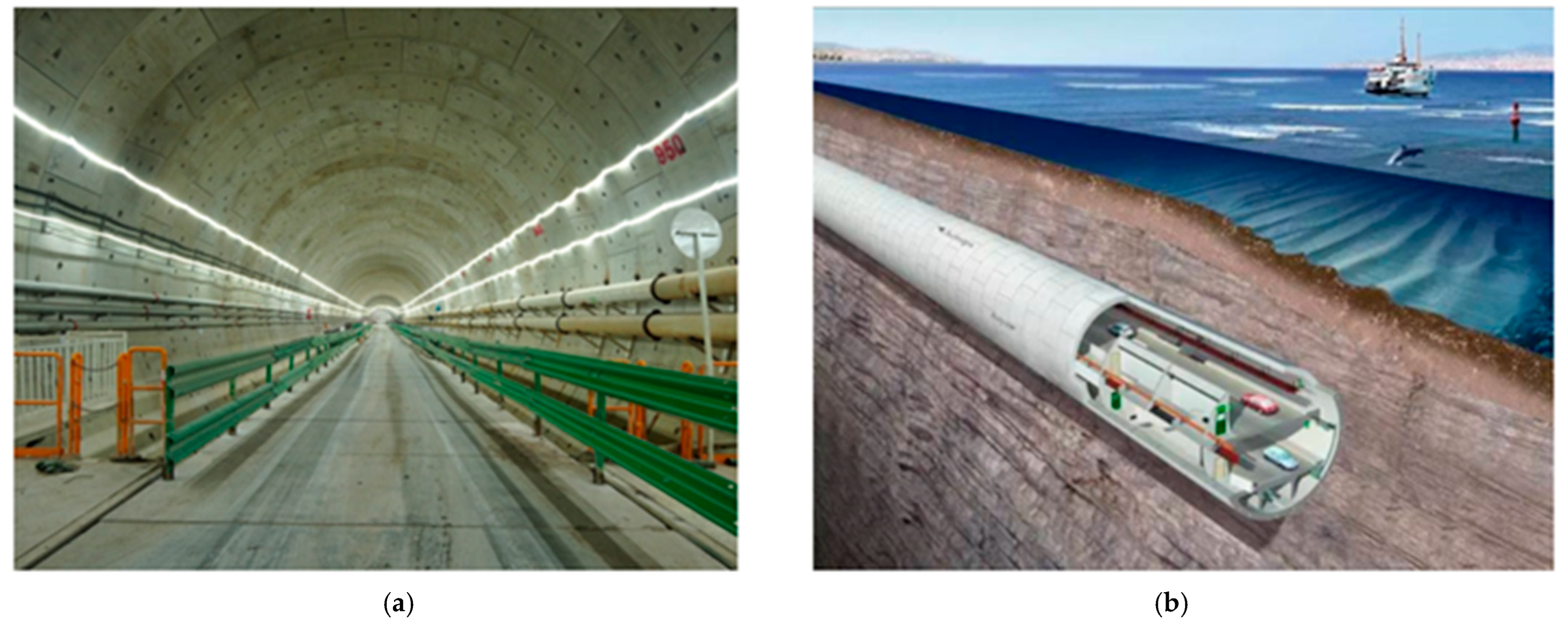
Figure 1. Deep-buried and subsea tunnels under high external water pressure: (a) interior view of the under-construction Mawan Undersea Tunnel, Shenzhen, China, adapted from Shenzhen Daily/EyeShenzhen; (b) schematic illustration of a subsea tunnel beneath high hydraulic head, redrawn by the authors based on general subsea tunnel configuration.
Jmse 14 01240 g001
Figure 2. Water inrush events during tunnel excavation under high groundwater pressure: (a) mud and water inrush rescue scene at Anshi Tunnel, Yunnan, China, adapted from Lincang Fire Rescue/Sina News; (b) representative tunnel water inrush scene showing high-pressure groundwater discharge through fractured surrounding rock.
Jmse 14 01240 g002
Figure 3. Schematic of external water pressure acting on the tunnel lining through surrounding rock and grouting under subsea conditions.
Jmse 14 01240 g003
Figure 4. Schematic of tunnel under water load. Modified after Wang et al. [67].
Jmse 14 01240 g004
Figure 5. Calculation model of a steady seepage field for a deep-buried tunnel adopted from [68].
Jmse 14 01240 g005
Figure 6. Conceptual framework of the reduction coefficient method for evaluating external water pressure in underwater tunnel design, showing the basic assumptions, governing parameters, applicability, and main limitations.
Jmse 14 01240 g006
Figure 7. Idealized axisymmetric model for analytical seepage calculation of external water pressure, showing concentric surrounding rock, grouting ring, and lining layers under hydraulic head.
Jmse 14 01240 g007
Figure 8. Conceptual framework of the theoretical analytical method for evaluating external water pressure on tunnel lining, including system idealization, fundamental assumptions, analytical modeling procedure, sensitivity analysis, derived relationships, method extensions, and main limitations.
Jmse 14 01240 g008
Figure 9. Comparison of FEM, FDM, and particle-based methods for simulating tunnel seepage, pore water pressure, stress response, and fracture-controlled permeability.
Jmse 14 01240 g009
Figure 10. Framework of numerical analysis for evaluating external water pressure on tunnel linings, illustrating the computational process, hydro-mechanical coupling modeling, solution procedure, and main limitations.
Jmse 14 01240 g010
Figure 11. Physical model test setup for investigating external water pressure on tunnel lining, showing the constant-head water supply, drainage system, pore water pressure transducers, and scaled tunnel model.
Jmse 14 01240 g011
Figure 12. Framework of physical model testing for evaluating external water pressure and tunnel stability, highlighting influencing factors, key investigations, outcomes, and main limitations.
Jmse 14 01240 g012
Figure 13. Schematic illustration of fluid flow through rock fractures, showing the effects of aperture, surface roughness, and normal stress on flow behavior.
Jmse 14 01240 g013
Figure 14. Conceptual framework of the single-fracture seepage-law approach for subsea tunnel design, illustrating the relationships among fracture aperture, stress-dependent deformation, permeability evolution, flow-channel formation, and the limitations of applying single-fracture behavior directly to tunnel-scale external water pressure assessment.
Jmse 14 01240 g014
Figure 15. Schematic framework of the equivalent continuum modeling approach for fractured rock masses, showing the upscaling from natural fractures to a representative elementary volume, equivalent continuum properties, anisotropic permeability tensor, and the coupled seepage–stress–deformation–permeability evolution around a subsea tunnel.
Jmse 14 01240 g015
Figure 16. Schematic illustration of the concept of the DFN model, demonstrating fracture network creation, flow through fractures, seepage through individual fractures, and statistics of macroscopic seepage properties.
Jmse 14 01240 g016
Figure 17. Seepage modeling approaches for fractured rock masses, comparing equivalent continuum models and discrete fracture network (DFN) models, and highlighting their representation methods and main limitations in high-pressure subsea tunnel conditions.
Jmse 14 01240 g017
Figure 18. Comparison between stress–damage coupling and stress–fracture coupling around tunnel linings: continuum damage mechanics represents distributed material degradation, whereas discrete fracture mechanics explicitly captures crack initiation, propagation, connectivity, and fracture-controlled seepage.
Jmse 14 01240 g018
Figure 19. Classification of coupled stress–seepage analysis models for high-pressure tunnels, including seepage–stress, seepage–stress–damage, and seepage–stress–fracture coupling approaches, with their key features, applications, and limitations.
Jmse 14 01240 g019
Figure 20. Schematic illustration of a hydro-mechanical discrete lattice model for crack-controlled seepage and external water pressure redistribution around the initial support of a drill-and-blast subsea tunnel.
Jmse 14 01240 g020
Figure 21. Schematic illustration of a hydro-mechanical discrete lattice model for simulating crack-controlled seepage and external water pressure redistribution around the initial support of a drill-and-blast subsea tunnel. The model represents fracture development, seepage through connected cracks, and pressure redistribution under high hydraulic loading.
Jmse 14 01240 g021
Table 1. Recommended reduction coefficient values (βe) corresponding to different groundwater conditions and their effects on surrounding rock stability.
LevelGroundwater Activity ConditionImpact of Groundwater on Surrounding Rock Stabilityβe Value
1Dry or damp tunnel wallNo significant impact0~0.20
2Seepage or dripping along structural planesWeathers filling materials in structural planes, reduces the shear strength of structural planes, softens weak rock mass0.10~0.40
3Heavy dripping, linear flow, or water spray along fractures or weak structural planesArgillizes filling materials in weak structural planes, reduces their shear strength, has a softening effect on medium-hard rock mass0.25~0.60
4Severe dripping, slight water inflow along weak structural planesGroundwater scours filling materials in structural planes, accelerates rock weathering, softens and argillizes weak zones such as faults, causes expansion and disintegration as well as mechanical piping. Seepage pressure can cause opening of weak layers0.40~0.80
5Severe jet flow, heavy water inflow along faults and weak zonesGroundwater scours and removes filling materials in structural planes, separates rock mass, creates seepage pressure that can open weak zones (e.g., faults) of certain thickness, leading to surrounding rock collapse0.65~1.00
Table 2. Key quantitative evidence supporting external water pressure assessment in high-head subsea and underwater tunnel conditions, including subsea tunnel cases, grouting and drainage studies, fractured rock seepage analyses, and hydraulically loaded tunnel-lining investigations.
OrderCategoryReferenceMain Values/Findings to Add
1Water pressure on subsea/underwater tunnels[29]For a Qingdao subsea tunnel case, the proposed reduction coefficient was generally 0.4–0.6; when the coefficient increased, the overall lining safety factor decreased from 2.58 to 1.29; the existing lining scheme was safe when the coefficient was <0.4. 
2Water inflow in subsea tunnels[35]In subsea tunnel simulations, no grouting ring produced water inflow of 4.4 m3·d−1·m−1; when grouting-ring thickness exceeded 6 m, the marginal reduction effect became weak.
3Subsea tunnel seepage/grouting/lining[217]Proposed analytical solutions for subsea tunnel seepage considering grouting and lining structure, and recommended a “blocking-based and limited drainage” design principle. 
4Deep-buried subsea tunnel/anisotropic seepage[80]For deep-buried subsea tunnels, a 10-fold increase in permeability anisotropy increased seepage discharge by 35.6%; when elastic-zone permeability was 100 times plastic-zone permeability, the plastic radius increased by 2–3 times. 
5Underwater subway tunnel/grouting reinforcement[218]After grouting, initial-support maximum and minimum principal stresses were about 4.7 MPa and 3.4 MPa; settlement and uplift were 12 mm and 14 mm, about 54% lower than without grouting. 
6Waterproof-drainage pressure reduction[219]A novel waterproof-drainage system reduced maximum lining water pressure to 0.6 MPa, compared with 0.86 MPa for a traditional drainage system and 1.7 MPa for a fully enclosed waterproof system. 
7Reduction coefficient/controlled drainage[67]Controlled drainage was proposed for tunnels under high water level; the study showed that a grouting zone alone cannot effectively reduce lining water pressure unless drainage measures are included. 
8Analytical/semi-analytical grouting-ring optimization[71]Derived axisymmetric analytical solutions for external water pressure and inflow; recommended grouting-ring thickness of 6 m and hydraulic-conductivity ratio of 100. 
9Numerical simulation/fractured rocks[42]External water pressure ranged from 0.2 to 2.12 MPa; pressure around powerhouse and steel branch pipes ranged from 1.4 to 1.72 MPa; concrete lining cracking increased pressure amplitude by 18.4–121.2%, with local pressure exceeding 2.0 MPa. 
10Numerical simulation/anisotropic and heterogeneous seepage[220]Investigated external water pressure under heterogeneous and anisotropic seepage conditions; emphasized that homogeneous analytical assumptions may be unrealistic for complex tunnel geology. 
11Physical model test/underwater mined tunnel[221]Large-scale 1:30 model tests were conducted under combined water and soil pressures to examine deformation, stress distribution, crack development, and failure mode of underwater mined-tunnel lining. 
12Physical model test/near-sea tunnel waterproofing[222]In Gongbei Tunnel model tests, PWW drainage reduced lining water pressure by up to 36.8%; under free drainage, lining strain decreased by about 30%. 
13Fractured/fault-zone tunnel field test[223]Field and numerical results showed that water pressure is highest at the invert and arch foot, moderate at the vault/spandrel, and lowest at the arch waist; macro-cracks can become seepage paths. 
14Hydraulic loading/lining behavior[224]Studied lining mechanical behavior under heavy rainfall conditions; useful as supporting evidence for hydraulic loading effects on lining stress and deformation. 
Table 3. Comparative summary of external water pressure assessment methods for drill-and-blast subsea tunnels, including their assumptions, advantages, limitations, and suitable engineering applications.
MethodMain AssumptionsMain AdvantagesKey Limitations for Drill-and-Blast Subsea TunnelsSuitable Use
Reduction coefficient methodExternal water pressure is treated as a reduced portion of hydrostatic pressure; simplified seepage and empirical coefficients are usedSimple, code-friendly, useful for preliminary designCannot capture fractured rock heterogeneity, excavation-induced permeability evolution, local leakage, support cracking, or nonuniform support–rock contactPreliminary design and engineering comparison
Theoretical analytical methodAxisymmetric geometry, homogeneous/isotropic medium, steady Darcy seepage, constant permeability, ideal lining–rock contactClear physical meaning; useful for parameter sensitivity and benchmark calculationsLimited for fractured rock masses, nonuniform support contact, transient seepage, damage evolution, and complex tunnel geometryMechanism explanation and reference calculation
Numerical analysis methodGeological model, boundary conditions, permeability law, and support–rock interaction must be predefinedCan model complex geometry, seepage–stress coupling, and spatial pressure distributionResults are highly parameter-sensitive; simplified models may still ignore progressive damage, fracture propagation, and support crackingDetailed engineering analysis and parametric studies
Physical model testingScaled hydraulic and structural conditions represent prototype behaviorEnables direct observation of seepage, deformation, pressure redistribution, and failure mechanismsLimited by similarity requirements, boundary simplification, cost, and difficulty reproducing coupled seepage–stress–damage processesModel validation and mechanism investigation
Equivalent continuum modelFractured rock is represented as an equivalent porous medium with averaged permeabilityComputationally efficient and suitable for large-scale analysisMay smooth out localized fracture flow, pressure concentration, and anisotropic seepage pathsRegional seepage assessment where fracture details are limited
Discrete fracture network modelIndividual fractures and their connectivity are explicitly representedCaptures anisotropic, channelized, and fracture-controlled seepageRequires detailed fracture data and can be computationally expensive; mechanical coupling is often limitedFracture-dominated seepage analysis
Coupled stress–seepage–damage/fracturing modelsPermeability evolves with stress redistribution, damage, and fracture developmentMost consistent with high-pressure fractured rock tunnel behaviorRequires advanced constitutive models, extensive parameters, and field/laboratory validationMechanism-based assessment and future design development
Hydro-mechanical discrete lattice modelsRock/support is represented by discrete lattice elements; cracks form through element degradation or breakage; seepage can be coupled with crack opening and flow pathsCaptures crack initiation, propagation, coalescence, and seepage through discrete cracksRequires careful parameter calibration; computationally expensive for full-scale tunnels; limited direct validation for drill-and-blast subsea tunnelsMeso-scale crack–seepage mechanism analysis and validation of crack-controlled external water pressure evolution
Disclaimer/Publisher’s Note: The statements, opinions and data contained in all publications are solely those of the individual author(s) and contributor(s) and not of MDPI and/or the editor(s). MDPI and/or the editor(s) disclaim responsibility for any injury to people or property resulting from any ideas, methods, instructions or products referred to in the content.