


Abstract
Side-by-side mooring alongside a quay is an effective strategy to enhance berth utilization and port efficiency. However, in confined waters, hydrodynamic interactions among adjacent ships and the quay wall can significantly alter ship motions, wave loads, mooring tensions, and fender reactions, thereby affecting operational safety. In this study, frequency- and time-domain numerical models of side-by-side moored ships at a quay were developed using the ANSYS AQWA 2025 R1 hydrodynamic analysis software (hereafter AQWA). The S175 and Wigley III hulls were selected as representative vessels. After model validation and mesh independence analysis, the hydrodynamic response of the inboard ship was examined under varying wave headings, water depths, quay boundary conditions, and outboard ship scales. Mooring loads were further analyzed under regular waves, irregular waves, and combined wave–current conditions. The results indicate that side-by-side mooring significantly modifies the sway, heave, and roll responses of the inboard ship. While the outboard ship generally provides a shielding effect, local response amplification may still occur within specific frequency ranges. The wave heading, shallow water, and quay wall effects play dominant roles in redistributing wave excitation forces, added mass, and radiation damping. Time-domain simulations reveal that ship-to-ship mooring lines S2 and S3 are the critical load-bearing components, especially under beam waves and certain oblique current directions. The use of polyester mooring lines effectively reduces peak tensions in critical lines but may increase fender reactions. These findings provide a reference for hydrodynamic safety assessment and mooring optimization in side-by-side berthing operations.
1. Introduction
Ports are essential nodes in maritime transportation systems, and their operational efficiency directly affects shipping capacity, logistics stability, and terminal service performance. Recent studies have also emphasized the role of intelligent perception, data-driven prediction, and port traffic monitoring in improving maritime navigation safety and port operation management [1,2,3]. With the continuous growth in vessel traffic and cargo throughput, many major ports are facing increasing pressure due to limited berth resources and terminal congestion. Compared with large-scale terminal expansion, side-by-side mooring provides a flexible and cost-effective operational strategy for improving berth utilization and reducing vessel waiting times. In this berthing mode, two ships are arranged in close proximity alongside the same quay, which can improve the terminal operational efficiency, and it is also applicable to shipbuilding, outfitting, cargo transfer, ship-to-ship support, and emergency operation scenarios [4,5].
However, side-by-side mooring alongside a quay introduces more complex hydrodynamic and mooring safety problems than conventional single-ship berthing. When two ships are moored in close proximity, the wave field around each hull is no longer governed by the single-body diffraction and radiation mechanism alone. Instead, the hydrodynamic interaction between the adjacent ships, the oscillatory flow in the narrow gap, and the wave reflection induced by the quay wall jointly modify the motion responses, wave excitation forces, added mass, radiation damping, mooring-line tensions, and fender reactions. These coupled effects may lead to excessive relative motion, the local overload of mooring lines, increased fender compression, and potential collision risks between the two ships or between the inboard ship and the quay. Therefore, a systematic investigation of the hydrodynamic responses and mooring load characteristics of side-by-side moored ships alongside a quay is necessary in order to improve the safety and reliability of such operations.
The hydrodynamic interaction of multiple floating bodies has been widely investigated using theoretical analysis, model tests, and numerical simulations. Early theoretical methods, such as strip theory and three-dimensional potential flow theory, provided fundamental tools for predicting ship motions and wave loads. For side-by-side floating bodies, previous studies have shown that the presence of a neighboring body can significantly alter the wave drift forces, radiation damping, and local free-surface elevation in the gap region [6,7]. In particular, gap resonance has been recognized as an important phenomenon in multi-body hydrodynamics, because the confined water between two closely spaced floating bodies may amplify local wave elevations and hydrodynamic loads under specific wave frequencies [8,9,10,11]. Recent experimental and numerical studies further indicate that the predicted gap-resonant response is closely related to the gap width, wave heading, hull geometry, and damping treatment, which highlights the necessity of careful model validation and cautious interpretation when potential flow-based methods are adopted for side-by-side floating bodies [12,13].
In addition to ship–ship interaction, the quay wall is another important factor affecting the hydrodynamic behavior of moored ships. Compared with open-water side-by-side arrangements, a vertical quay wall reflects incident and radiated waves, changes the local wave energy distribution, and modifies the boundary conditions around the inboard ship. The combined ship–ship–quay interaction may therefore result in response amplification or suppression in different frequency ranges. Previous studies on vessel–quay systems and gap resonance near vertical walls have demonstrated that the quay boundary can significantly influence wave forces and motion responses [14,15]. Recent investigations further show that the resonance characteristics of confined water regions are affected not only by the quay–ship gap distance but also by the coexistence of ship–ship and ship–quay gap modes, which may lead to more complicated response amplification in side-by-side berthing configurations [16]. Nevertheless, the combined effects of ship–ship interaction and quay wall confinement on the frequency-domain response in side-by-side moored ships still require further investigation, especially from the perspective of operational safety.
Mooring safety is a key issue in side-by-side berthing operations. Mooring lines and fenders provide the direct constraints required to maintain the relative positions of ships and to prevent excessive drift or collision. The load distribution in a mooring system is affected by the ship motions, wave direction, current direction, line stiffness, line material, fender arrangement, and coupling between adjacent hulls. For side-by-side moored ships, ship-to-ship mooring lines are particularly important because they directly restrain the relative motion between the two vessels. Existing studies have analyzed the mooring loads of berthed ships and floating systems under wind, wave, and current loads using quasi-static, dynamic, and numerical methods [17,18,19]. Numerical studies based on the ANSYS AQWA hydrodynamic analysis software (hereafter AQWA) and time-domain simulations have also been applied to side-by-side tankers, temporary offshore berthing systems, and multiple vessels moored side by side in harbors [20,21,22]. Beyond maritime engineering, coupled dynamic modeling has also been applied to the safety assessment of complex systems under stochastic environmental excitations. For example, Chen et al. [23] evaluated the performance and safety of rack vehicles in mountainous regions under pulsating wind loads, showing that non-stationary environmental loading and the system configuration can significantly affect dynamic stability, safety margins, and load transfer paths. Zhou et al. [24] used CFD to study refueling at sea, and their work serves as a foundation for the present investigation. These studies indicate that the safety of complex multi-body systems should be evaluated by considering both environmental excitation mechanisms and structural constraint responses.
Despite these advances, several issues remain insufficiently clarified for side-by-side moored ships alongside a quay. First, many existing studies focus mainly on hydrodynamic interaction or gap resonance, whereas the direct connection between frequency-domain response mechanisms and time-domain mooring load extremes is not always explicitly established. Second, most studies consider open-water side-by-side arrangements or simplified geometries, while the combined influence of the quay wall, finite water depth, wave heading, and ship-scale differences has received comparatively less attention. Third, although potential flow-based solvers are efficient for design-oriented studies, their applicability to roll motion, gap-related response amplification, and mooring load prediction should be assessed with appropriate damping treatment, validation, and limitation statements. Therefore, a design-oriented framework is needed to connect frequency-domain hydrodynamic characteristics with time-domain mooring safety assessment for side-by-side mooring alongside a quay.
To address these issues, this study investigates the hydrodynamic response and mooring load characteristics of two non-identical ships moored side by side alongside a quay based on ANSYS AQWA. The S175 and Wigley III hulls are selected as representative vessels. A frequency-domain model is first established to analyze the hydrodynamic response of the inboard ship under single-ship and side-by-side conditions. The effects of the wave heading, water depth, quay wall boundary, and outboard ship scale are then examined. A shielding efficiency index is introduced to quantify the influence of the outboard ship on the inboard ship and to distinguish global shielding from local response amplification. Furthermore, a time-domain mooring model is developed to evaluate mooring line tensions and fender reactions under regular waves, irregular waves, and combined wave–current conditions. Finally, optimization schemes for critical mooring lines are compared from the perspective of mooring safety.
The novelty of this work does not lie in developing a new hydrodynamic theory but in establishing a systematic engineering assessment framework that links frequency-domain hydrodynamic mechanisms with time-domain mooring safety evaluation for side-by-side moored ships alongside a quay. Specifically, this study identifies heading-dependent shielding and local amplification effects, examines the influence of quay wall confinement and water depth variation, and further relates the identified frequency-domain response characteristics to the extreme tensions of critical ship-to-ship mooring lines and fender reactions. This provides a clearer connection between hydrodynamic interaction mechanisms and practical mooring safety assessment.
The main contributions of this study are summarized as follows:
- A coupled frequency-domain and time-domain numerical framework is established for two non-identical ships moored side by side alongside a quay, enabling hydrodynamic response analysis and mooring safety evaluation within a unified procedure.
- A shielding efficiency index is introduced to quantify the influence of the outboard ship on the inboard ship. This index is used to distinguish the overall shielding effect from local response amplification in specific frequency ranges.
- The effects of the wave heading, water depth, quay wall boundary, and outboard ship scale on the hydrodynamic response of the inboard ship are analyzed, and unfavorable wave headings are identified based on both the motion response and wave excitation characteristics.
- The time-domain mooring loads under irregular waves and wave–current conditions are evaluated. Critical ship-to-ship mooring lines are identified, and optimization schemes involving different line materials and diameters are compared.
The remainder of this paper is organized as follows. Section 2 presents the numerical model, governing equations, shielding efficiency index, and mooring system model. Section 3 analyzes the frequency-domain hydrodynamic response of the side-by-side moored system under different influencing factors. Section 4 investigates the time-domain mooring loads and evaluates the optimization schemes for critical mooring lines. Section 5 discusses the hydrodynamic mechanism, engineering implications, and model limitations. Section 6 summarizes the main conclusions.
2. Numerical Model and Methodology
2.1. Coordinate System and Environmental Conditions
A fixed global coordinate system and body-fixed local coordinate system were adopted to describe the motion of the side-by-side moored system, following common seakeeping and AQWA hydrodynamic modeling conventions [25,26,27]. The origin of each body-fixed coordinate system was located at the center of gravity of the corresponding ship (Figure 1). Both coordinate systems followed the right-hand rule, and the vertical Z-axis was defined as positive upward. The incident wave direction was measured counterclockwise from the positive X-axis to the wave propagation direction. In this definition, represents following waves, represents beam waves, and represents head waves.
Figure 1.
Coordinate system and wave heading definition.
The main input settings used in the AQWA frequency-domain and time-domain simulations are summarized in Table 1. In the frequency-domain analysis, regular-wave diffraction/radiation calculations were conducted over the wave frequency range of –. The heading-dependent response was first examined using a heading interval, and representative headings were then selected for detailed comparison and time-domain mooring load analysis. In the time-domain analysis, irregular waves were generated using the JONSWAP spectrum. The simulation time step, ramp time, total duration, wave headings, current directions, and random-wave realization settings are also listed in Table 1.
Table 1.
Consolidated input settings for the AQWA frequency-domain and time-domain simulations.
2.2. Ship Geometry and Quay Arrangement
The S175 and Wigley III hulls were selected as representative ships for the numerical investigation. The S175 ship was arranged as the inboard ship, while the Wigley III ship was arranged as the outboard ship. The two ships were placed side by side alongside a vertical quay wall (Figure 2). The quay model had a longitudinal length of , a transverse width of , and a vertical height of . The principal dimensions and inertial parameters of the two ships are listed in Table 2.
Figure 2.
Numerical model of the side-by-side moored ships alongside a quay.
Table 2.
Principal dimensions of the S175 and Wigley III hulls.
2.3. Frequency-Domain Hydrodynamic Model
The hydrodynamic analysis was performed using ANSYS AQWA, which is based on three-dimensional linear potential flow theory [25,26,27]. The fluid was assumed to be incompressible, inviscid, and irrotational. Under these assumptions, the velocity potential satisfies the Laplace equation in the fluid domain, as given in Equation (1):
The velocity potential satisfies the linear free-surface boundary condition, the seabed boundary condition, the body boundary condition, and the far-field radiation condition. On the wetted body surface, the non-penetration condition can be written as in Equation (2):
where is the velocity vector of a point on the body surface, and is the outward unit normal vector.
In a multi-body system, the velocity potential around each floating body is affected by the existence and motion of the other bodies. Therefore, the boundary conditions are imposed simultaneously on the mean wetted surfaces of all floating bodies. The radiation and diffraction problems are solved using the boundary element method, and the hydrodynamic coefficients and wave excitation forces are obtained in the frequency domain.
The linear equation of motion for the floating body in the frequency domain is expressed as in Equation (3):
where is the wave circular frequency, is the mass matrix, is the added mass matrix, is the radiation damping matrix, is the hydrostatic restoring stiffness matrix, is the complex motion response vector, and is the first-order wave excitation force vector, while is the imaginary unit. The response vector is written as , corresponding to surge, sway, heave, roll, pitch, and yaw, respectively. The excitation vector is written as , where , , and are the wave excitation forces and , , and are the wave excitation moments about the corresponding axes.
The hydrostatic restoring matrix in the frequency-domain equation of motion was obtained from the AQWA hydrostatic analysis. To make the restoring characteristics checkable, the main hydrostatic and stability parameters of the baseline S175 and Wigley III models are summarized in Table 3. For small-amplitude motions, the heave, roll, and pitch restoring terms are mainly governed by the waterplane area, displacement volume, and metacentric heights. In particular, the transverse metacentric height is closely related to the roll restoring moment and the roll response peak.
Table 3.
Hydrostatic stability parameters of the baseline S175 and Wigley III models.
For the side-by-side system, the hydrodynamic coupling between the two ships was included in the multi-body equation of motion. The response amplitude operator (RAO) was defined as in Equation (4):
where a is the incident wave amplitude, and denotes the complex motion amplitude of the selected degree of freedom. For the six-degree-of-freedom motion analysis, the translational responses correspond to surge, sway, and heave, while the rotational responses correspond to roll, pitch, and yaw.
2.4. Damping Correction for Gap Resonance and Roll Motion
AQWA frequency-domain hydrodynamic analysis is based on three-dimensional linear potential flow theory, which can efficiently provide the added mass, radiation damping, and wave excitation forces of the ship system. However, because potential flow theory is established under the inviscid assumption, it cannot directly represent viscous dissipation, vortex shedding, or the local energy loss in the narrow gap between two adjacent ships. For the side-by-side moored system alongside a quay, the confined water in the gap region may exhibit pronounced free-surface oscillation under wave action, while the roll response may also be overestimated near the resonance frequency if viscous damping is insufficiently represented. Therefore, damping correction was introduced into the numerical model.
To improve the numerical prediction of the gap water motion and roll response, a damping lid was applied to the free-surface region between the two ships, and additional roll damping was introduced into the roll degree of freedom. The damping lid was used to represent the equivalent energy dissipation associated with the oscillation of the confined water in the narrow gap, while the additional roll damping was used to compensate for the insufficient viscous dissipation of the potential flow model in roll motion. The damping lid coefficient of 0.03 was selected as an engineering value following previous potential flow studies of narrow-gap resonance problems [11,13]. It was further checked in the present sensitivity comparison, where the damping lid reduced the excessive roll response peak while preserving the main peak frequency range and the overall RAO trend. The additional equivalent roll damping was rounded to three significant figures and taken as .
The damping parameters adopted in this study are treated as equivalent engineering parameters rather than calibrated physical constants. Previous studies on side-by-side vessels and narrow-gap floating systems have shown that potential flow methods may overestimate the gap resonance and roll response peaks due to the absence of viscous dissipation, and damping lid or artificial damping treatments have therefore been commonly introduced to improve engineering predictions. Following this approach, as reported by Pauw et al., Yue et al., and Chen et al., a damping lid coefficient of 0.03 was adopted in the present AQWA model, and additional equivalent linear roll damping was applied. The sensitivity comparison shows that these corrections mainly reduce the response peak magnitude while preserving the dominant sensitive frequency range and overall RAO trend. Thus, the model is suitable for design-level comparative assessment and the identification of unfavorable headings, sensitive response modes, and critical mooring lines, although the absolute roll RAOs and S2/S3 peak tensions should not be regarded as fully calibrated full-scale predictions.
To evaluate the influence of the damping correction on the numerical results, three cases were compared under the baseline side-by-side mooring condition in beam waves, as summarized in Table 4. Case D0 represents the original potential flow result without damping correction. Case D1 includes only the damping lid in the gap region. Case D2 includes both the damping lid and the additional roll damping. The damping condition D2 was adopted in the subsequent frequency-domain and time-domain analyses.
Table 4.
Damping correction cases used in the numerical model.
Figure 3 shows the comparison of the roll RAOs of the inboard ship under the three damping cases. In Case D0, without any damping correction, a pronounced roll resonance peak appears near , corresponding to a period of approximately according to . This peak is consistent with the relatively small transverse metacentric height of the S175 model listed in Table 3. This indicates that the potential flow model may overestimate the roll response because of insufficient viscous dissipation. After introducing the damping lid, the peak roll RAO in Case D1 decreases to 2.65, which indicates that the damping lid can partly suppress the amplification induced by the oscillation of the gap water. When both the damping lid and the additional roll damping are applied, the peak roll RAO in Case D2 is further reduced to 2.31, showing that the additional roll damping provides more direct suppression of the roll resonance peak.
Figure 3.
Comparison of roll RAOs under different damping correction cases.
It is also observed that the peak frequencies of the three cases remain concentrated within the range of –. This indicates that the damping correction does not alter the main sensitive frequency range of the roll response, but mainly reduces the response magnitude near resonance. In addition, the overall variation trends of the three RAO curves remain generally consistent, suggesting that the damping correction does not change the primary hydrodynamic mechanism of the side-by-side moored system. Therefore, Case D2 was selected as the baseline model for the subsequent hydrodynamic and mooring analyses in order to mitigate the possible overestimation of roll resonance in the potential flow calculation. It should be emphasized that the adopted damping parameters are equivalent engineering correction parameters rather than calibrated physical constants; therefore, the damping-corrected results are mainly used for the comparative assessment of response trends and critical conditions.
It should be noted that the damping correction adopted here is essentially an engineering treatment for improving the numerical prediction of roll motion and gap water oscillation. The purpose of introducing the damping lid and additional roll damping is not to reproduce the detailed viscous dissipation mechanism in the ship–ship gap, but to mitigate the possible overestimation of the roll and gap-related response peaks caused by the inviscid potential flow assumption. The comparison among the damping cases shows that the correction mainly changes the peak magnitude, while the dominant sensitive frequency range and the relative variation trends remain generally unchanged. Therefore, the AQWA model with empirical damping is considered suitable for design-level comparative assessment, such as identifying unfavorable wave headings, critical response modes, and relatively high-risk mooring lines. However, the corrected results should not be interpreted as fully calibrated absolute predictions of the roll amplitude or gap-resonant response.
The sensitivity of the critical ship–ship mooring line tensions to the additional roll damping was further examined under the governing irregular beam wave condition. As shown in Table 5, without the additional roll damping, the maximum tensions of S2 and S3 are 867.91 kN and 790.99 kN, respectively. After introducing the additional roll damping, the corresponding values become 884.21 kN and 720.24 kN. The relative changes are approximately +1.9% for S2 and for S3. This indicates that the additional roll damping affects the absolute peak values of the ship–ship mooring line tensions, especially for S3, but it does not change the identification of the critical mooring lines or the governing beam wave condition. In both damping cases, S2 and S3 remain the most critical ship–ship mooring lines, and the wave heading remains the most unfavorable wave condition for the present mooring arrangement.
Table 5.
Sensitivity of critical ship–ship mooring line tensions to additional roll damping under the governing irregular beam wave condition.
2.5. Shielding Efficiency Index
To quantify the influence of the outboard ship on the motion response of the inboard ship, a shielding efficiency index was introduced. For the j-th degree of freedom, the frequency-dependent shielding efficiency is defined as
where is the RAO of the inboard ship under the side-by-side condition, is the corresponding RAO of the single-ship condition, and is the wave heading. The subscript j denotes the degree of freedom, with –6 corresponding to surge, sway, heave, roll, pitch, and yaw, respectively. The shielding efficiency index is expressed as a percentage. A positive value indicates that the side-by-side arrangement reduces the response of the inboard ship, corresponding to shielding. A negative value indicates that the response is amplified relative to the single-ship condition, corresponding to local amplification.
To evaluate the overall shielding level within a specified frequency range, the average shielding efficiency was further defined as
where and are the lower and upper limits of the investigated frequency range, respectively.
Since the peak frequencies of the single-ship and side-by-side conditions may differ, the characteristic shielding efficiencies at the original single-ship peak and at the new side-by-side peak were also examined. This treatment helps to identify local amplification that may be masked by the frequency-averaged result. In this study, positive values over a broad frequency band are interpreted as global shielding, whereas negative values near specific frequencies indicate local amplification caused by gap water oscillation, quay wall reflection, or multi-body hydrodynamic interaction.
2.6. Time-Domain Mooring Model
A time-domain mooring model was established based on the hydrodynamic coefficients obtained from the frequency-domain analysis. The two ships were treated as rigid bodies with six degrees of freedom. The mooring system consisted of quay–ship mooring lines, ship–ship mooring lines, quay–ship fenders, and ship–ship fenders. The mooring lines were modeled as tension-only linear elastic elements, while the fenders were modeled as compression-only contact elements.
In the present time-domain model, the mooring lines were represented as tension-only equivalent linear elastic elements. The initial pretension was included through the static equilibrium state before the environmental loads were applied. When a line became slack, its axial restoring force was set to zero. However, line inertia, material hysteresis, snap load effects during slack–taut transitions, and nonlinear load–elongation behavior were not explicitly considered. The fenders were modeled as compression-only elements with equivalent linear stiffness, and detailed nonlinear force–deflection curves and rate-dependent effects were neglected. These simplifications are acceptable for the comparative purpose of this study, but they may affect the absolute peak values of line tensions and fender reactions. Therefore, the mooring load results are mainly used to compare different environmental conditions and identify critical lines and fenders, rather than as fully detailed full-scale predictions.
In the present time-domain model, the mooring lines were represented by tension-only equivalent linear elastic elements. The initial equilibrium distance between the two line endpoints after the calm-water pretension analysis is denoted as , which corresponds to the “Distance” column in Table 6. The equivalent line stiffness was calculated as
where is an equivalent linear rigidity parameter used in the numerical mooring model. The unstretched length was then determined from the prescribed pretension as
Accordingly, the axial tension of a tension-only mooring line was calculated as
When the calculated line tension became negative, the line was regarded as slack and no restoring force was applied. Similarly, the fender reaction was considered only when contact compression occurred.
Table 6.
Parameters of the baseline mooring lines.
The mooring arrangement used in the time-domain analysis is shown in Figure 4. The mooring system included six quay–ship mooring lines, denoted as M1–M6, and four ship–ship mooring lines, denoted as S1–S4. The quay–ship fenders and ship–ship fenders were arranged to limit the contact force between the ship and quay and between the two ships.
Figure 4.
Mooring line and fender arrangement of the side-by-side moored system.
2.7. Model Validation and Mesh Independence
Before conducting the side-by-side hydrodynamic analysis, the numerical model was validated using published single-ship RAO data. The heave and pitch RAOs of the Wigley III and S175 hulls were calculated and compared with reference results [28,29], as shown in Figure 5. The comparison shows that the present AQWA results reproduce the main response trends, peak frequency regions, and high-frequency attenuation characteristics of the reference data. Minor discrepancies can be observed near the response peaks, which may be attributed to geometric simplification, mesh discretization, and the limitations of linear potential flow theory. Overall, the agreement is considered sufficient to support the single-ship diffraction–radiation modeling procedure and the subsequent comparative numerical analysis under the specified modeling assumptions.
Figure 5.
Comparison of single-ship RAOs between the present AQWA results and reference data.
It should be noted that the present validation is limited to the single-ship heave and pitch RAOs using available benchmark data. This validation supports the basic diffraction–radiation modeling procedure, mesh quality, and motion response prediction of the individual hulls. However, direct experimental validation of the full side-by-side ship–ship–quay configuration was not possible in this study. Therefore, the predicted multi-body gap flow interaction, shielding effect, and coupled mooring load responses in the following sections should be interpreted mainly as comparative numerical trends under the specified assumptions, rather than as fully validated absolute design values. Further physical model tests or field measurements are needed to quantitatively validate the coupled multi-body responses.
A mesh independence analysis was further conducted to evaluate the sensitivity of the hydrodynamic results to the panel size. Three mesh schemes were considered, as listed in Table 7. The sway wave excitation force of the outboard Wigley III ship was selected as the representative quantity because it is sensitive to transverse wave loading and ship–ship interaction. The grid convergence index was used to quantify the numerical uncertainty following the standard grid refinement uncertainty assessment procedure [30,31] (see Table 8).
Table 7.
Mesh schemes used in the mesh independence analysis.
Table 8.
Quantitative summary of the mesh refinement uncertainty assessment.
As shown in Figure 6, the three mesh schemes produce similar frequency-dependent trends and peak locations. The grid convergence index of the representative peak response is 1.32%, and the ratio GCI12/GCI23 is 0.43, indicating that the numerical uncertainty associated with mesh refinement is limited. Considering both the accuracy and computational cost, the medium mesh scheme M2 was adopted in the subsequent hydrodynamic and mooring analyses.
Figure 6.
Mesh independence analysis based on the sway wave excitation force of the outboard Wigley III ship.
3. Frequency-Domain Hydrodynamic Response
After the numerical model validation and damping correction described in Section 2, the frequency-domain hydrodynamic response of the side-by-side moored system was further analyzed. In the following simulations, Case D2, which includes both the damping lid in the gap region and the additional roll damping correction, was adopted as the baseline model. This treatment was used to mitigate the possible overestimation of the roll resonance and gap water oscillation in the potential flow calculation.
The analysis in this section focuses on the inboard S175 ship, because its motion response and mooring safety are directly affected by the outboard ship, the narrow gap flow, and the quay wall boundary. The sway, heave, and roll motions were selected as the main sensitive degrees of freedom. These motion components are closely related to the transverse wave excitation, vertical gap water oscillation, and ship–ship relative motion and therefore have direct implications for mooring line tensions and fender reactions in the subsequent time-domain analysis.
3.1. Comparison Between Single-Ship and Side-by-Side Conditions
To clarify the influence of the outboard ship on the hydrodynamic response of the inboard ship, the RAOs of the inboard S175 ship under side-by-side mooring were compared with those of a single S175 ship. The comparison was conducted under the beam wave condition, namely , because this wave heading produces strong transverse excitation and is commonly regarded as a critical condition for moored ships alongside a quay.
As shown in Figure 7, the side-by-side arrangement significantly changes the frequency-domain response of the inboard ship. Among the six degrees of freedom, sway, heave, and roll are more sensitive to the presence of the outboard ship. For the single-ship condition, the roll and heave responses exhibit evident peaks in the low-frequency range, while the surge response remains relatively small. Under the side-by-side condition, the response of the inboard ship is modified by the shielding effect of the outboard ship and by the local fluid motion in the narrow gap between the two ships.
Figure 7.
Comparison of the six-degree-of-freedom RAOs of the S175 ship under single-ship and side-by-side conditions in beam waves.
For the sway motion, the response of the inboard ship is reduced in part of the frequency range, indicating that the outboard ship can weaken the direct transverse wave excitation. However, this reduction is not uniform over the entire frequency range. Local differences between the single-ship and side-by-side results still appear near the response peak region, which suggests that the side-by-side configuration changes not only the magnitude of the motion response but also the hydrodynamic environment around the inboard ship.
For the heave motion, the side-by-side condition produces a more complex variation. In some frequency ranges, the heave response of the inboard ship is lower than that of the single ship, showing the shielding effect of the outboard ship. In other frequency ranges, local amplification may occur because of the confined vertical fluid motion in the gap region and the reflection effect of the quay wall. This indicates that the heave response of the inboard ship is controlled by the combined effects of wave shielding, gap water oscillation, and radiation energy dissipation.
For the roll motion, the side-by-side arrangement also produces a clear modification of the response curve. Although the additional damping correction suppresses the excessive roll resonance peak, the roll response remains sensitive in the low-frequency range. The change in roll response is not only related to the external wave excitation moment but is also associated with the redistribution of added inertia, radiation damping, and heave–roll coupling induced by the multi-body interaction.
Overall, the comparison between the single-ship and side-by-side conditions shows that the outboard ship does not simply reduce the motion response of the inboard ship over the whole frequency range. Instead, the hydrodynamic interaction exhibits a frequency-dependent feature. The outboard ship can provide an overall shielding effect in some frequency bands, while local response amplification may still occur near specific frequencies. Therefore, the hydrodynamic safety assessment of side-by-side mooring should not rely only on single-ship response characteristics.
3.2. Shielding Effect and Local Response Amplification
To further quantify the influence of the outboard ship on the inboard ship, the shielding efficiency defined in Section 2 was calculated for the sway, heave, and roll motions. Figure 8 shows the frequency-dependent shielding efficiency of the inboard S175 ship under the beam wave condition.
Figure 8.
Shielding efficiency of the inboard ship in sway, heave, and roll under beam waves.The gray horizontal line denotes zero shielding efficiency.
As shown in Figure 8, the shielding efficiency is generally positive in part of the investigated frequency range, indicating that the outboard ship can reduce the motion response of the inboard ship under beam waves. However, negative values also appear in some local frequency regions, which means that the side-by-side arrangement may amplify the response of the inboard ship under specific hydrodynamic conditions.
This result indicates that the shielding effect of the outboard ship is not uniform over the entire frequency range. The side-by-side mooring condition produces a combined effect of wave shielding, gap water oscillation, and multi-body hydrodynamic coupling. Therefore, the outboard ship may reduce the inboard ship response in some frequency ranges, while local response amplification can still occur near certain response peaks. This frequency-dependent behavior is important for identifying unfavorable wave conditions and evaluating the mooring safety of side-by-side berthing operations.
3.3. Hydrodynamic Coefficients of the Inboard Ship
To explain the variation in the motion response from the perspective of hydrodynamic mechanisms, the added mass and radiation damping of the inboard ship were compared between the single-ship and side-by-side conditions. Figure 9 presents the added mass and radiation damping coefficients of the inboard S175 ship in sway, heave, and roll.
Figure 9.
Comparison of the added mass and radiation damping coefficients of the inboard S175 ship under single-ship and side-by-side conditions.
The results show that the hydrodynamic coefficients of the inboard ship are significantly modified by the presence of the outboard ship. In the low-frequency and high-frequency ranges, the overall trends of the single-ship and side-by-side cases are relatively similar. However, in the intermediate frequency range, the added mass and radiation damping exhibit more obvious differences, especially in sway and heave. This indicates that the outboard ship changes the local flow field around the inboard ship and modifies the fluid inertia and radiation energy dissipation characteristics.
For sway motion, the presence of the outboard ship restricts the transverse flow around the inboard ship, leading to the redistribution of the added mass and radiation damping. For heave motion, the confined fluid in the narrow gap between the two ships produces additional vertical fluid motion, which affects both the added inertia and the energy dissipation mechanism. For roll motion, the variation in the direct roll added mass and radiation damping is relatively moderate, but the roll response is still strongly affected by the coupling between heave and roll motions.
To further examine this coupling effect, the heave–roll coupling terms of added mass and radiation damping were analyzed. As shown in Figure 10, the side-by-side condition strengthens the coupling between heave and roll in the key frequency range. This suggests that the gap water motion can transfer energy between vertical motion and roll motion, thereby affecting the roll response of the inboard ship.
Figure 10.
Heave–roll hydrodynamic coupling of the S175 ship under single-ship and side-by-side conditions.
Overall, the changes in the hydrodynamic coefficients demonstrate that the difference between the single-ship and side-by-side responses is not only caused by the variation in external wave excitation but also by the redistribution of fluid inertia, radiation damping, and motion coupling induced by the multi-body interaction.
3.4. First-Order Wave Excitation Forces
The motion response of a floating body is directly related to the external wave excitation. Therefore, the first-order wave excitation forces and moments of the inboard ship were compared under the single-ship and side-by-side conditions. Figure 11 shows the sway force, heave force, and roll moment of the inboard S175 ship under beam waves. In this figure, denotes the sway wave excitation force, denotes the heave wave excitation force, and denotes the roll wave excitation moment.
Figure 11.
Comparison of the first-order wave excitation forces and roll moments of the inboard S175 ship under single-ship and side-by-side conditions in beam waves.
The results indicate that the side-by-side arrangement changes the wave excitation characteristics of the inboard ship. For the sway force, the outboard ship provides an evident shielding effect in part of the frequency range, reducing the direct transverse wave excitation on the inboard ship. However, the sway force does not decrease monotonically over the entire frequency range, indicating that the gap flow and the quay wall reflection still influence the transverse load distribution.
For the heave force, the side-by-side condition produces a more complex response. Although the outboard ship reduces the heave excitation in some frequency ranges, local amplification may appear near the frequency range where the confined gap water oscillates more strongly. This phenomenon indicates that the heave excitation is affected by both external wave shielding and internal gap water motion.
For the roll moment, the side-by-side condition changes the wave-induced moment acting on the inboard ship, but the variation in the roll response cannot be explained only by the external roll moment. The combined effects of added inertia, radiation damping, heave–roll coupling, and additional damping correction should also be considered. This further demonstrates that the roll response of the inboard ship under side-by-side mooring is governed by a coupled hydrodynamic mechanism.
3.5. Effects of Wave Heading
Wave heading is one of the most important environmental parameters affecting the hydrodynamic response of the side-by-side moored system. To investigate its influence, the wave heading was varied from to , and the RAOs of the inboard ship were calculated. Figure 12 shows the RAO contour maps of sway, heave, and roll with respect to the wave frequency and wave heading.
Figure 12.
Contour maps of the sway, heave, and roll RAOs of the inboard ship under different wave headings.
As shown in Figure 12, the three sensitive degrees of freedom exhibit strong dependence on the wave heading. The sway and heave responses are relatively high in the wave heading range of approximately –, where the transverse wave component is significant. The roll response also shows pronounced amplification in this range, while some oblique wave headings, such as – and around , may also induce considerable roll responses.
This result indicates that the beam wave condition is not the only unfavorable wave direction for the side-by-side moored system. Although usually produces strong transverse excitation, some oblique wave conditions can also induce local response amplification because of the combined effects of wave diffraction, ship–ship shielding, gap water oscillation, and quay wall reflection.
To identify unfavorable wave headings more quantitatively, the characteristic shielding efficiency and the maximum RAO of each degree of freedom were considered together. The identified unfavorable wave headings are summarized in Table 9.
Table 9.
Identified unfavorable wave headings for different degrees of freedom.
It can be seen from Table 9 that the high-response region of sway and heave is mainly concentrated near –, while surge and roll may become unfavorable under certain oblique wave headings. This means that the operational safety assessment of side-by-side mooring should not be limited to the beam wave condition. Instead, both beam waves and specific oblique waves should be considered when identifying unfavorable environmental conditions.
The first-order wave excitation forces under representative wave headings were further analyzed, as shown in Figure 13. The results show that the sway force, heave force, and roll moment do not increase monotonically toward the beam wave direction. Instead, several local peaks appear under specific oblique wave headings and frequency ranges.
Figure 13.
First-order wave excitation forces and roll moments of the inboard ship under representative wave headings.
These results further confirm that the unfavorable wave direction of a side-by-side moored system cannot be determined solely based on geometric intuition or the beam wave assumption. A combined analysis of the motion response, shielding efficiency, and wave excitation force is necessary for reliable safety assessment.
3.6. Effects of Water Depth
The influence of the water depth was investigated by keeping the ship geometry, draft, quay boundary, and side-by-side arrangement unchanged. Five water depth conditions were considered, as listed in Table 10. The water depth of was used to approximate the deep-water condition, while the other cases were used to examine the effects of a finite water depth and seabed confinement.
Table 10.
Water depth cases used in the frequency-domain analysis.
Figure 14 shows the RAOs of the inboard ship under different water depths. The results indicate that the water depth has a significant influence on the sway, heave, and roll responses. Under shallow-water conditions, the seabed boundary restricts the fluid motion beneath the hull and within the gap region, which changes the added inertia and radiation energy dissipation of the system.
Figure 14.
Effects of water depth on the sway, heave, and roll RAOs of the inboard ship under beam waves.
For sway and roll motions, the response peaks tend to shift toward the lower-frequency range as the water depth decreases. The low-frequency response is also more pronounced under shallow-water conditions, especially when the water depth is . This indicates that shallow water can enhance the constrained-flow effect and increase the sensitivity of the side-by-side system to low-frequency wave excitation.
For heave motion, the influence of the water depth is more frequency-dependent. A decrease in water depth does not necessarily reduce the heave response over the entire frequency range. Instead, local amplification may occur in certain frequency regions. Therefore, shallow water may increase the risk of larger mooring line tensions, sustained fender compression, and relative motion between the two ships.
3.7. Effects of Quay Wall Boundary
The quay wall is an essential boundary condition for ships moored alongside a berth. To evaluate its influence, the hydrodynamic responses of the side-by-side system with and without the quay wall were compared. Figure 15 shows the RAOs of the inboard ship under the two boundary conditions.
Figure 15.
Comparison of the sway, heave, and roll RAOs of the inboard ship with and without the quay wall under beam wave conditions.
The results show that the quay wall significantly modifies the frequency-domain response of the inboard ship. For sway motion, the quay wall changes the transverse wave field and modifies the response level in the low- and intermediate-frequency ranges. For heave motion, the quay wall tends to increase the response peak in certain frequency regions, indicating that wave reflection from the vertical boundary can enhance the vertical wave energy around the inboard ship. For roll motion, the quay wall suppresses the low-frequency peak in some cases, showing that the quay boundary may either amplify or reduce the response depending on the degree of freedom and frequency range.
3.8. Effects of Outboard Ship Scale
The relative scale of the outboard ship may influence the shielding ability and the gap flow characteristics of the side-by-side system. To examine this effect, three outboard ship scale ratios were considered, as listed in Table 11. The inboard S175 ship, the gap distance, the quay wall boundary, and the environmental conditions were kept unchanged.
Table 11.
Outboard ship scale cases.
Figure 16 shows the sway, heave, and roll RAOs of the inboard ship under different outboard ship scales. The curves of the three cases are generally close to each other, indicating that the variation in the outboard ship scale has a limited influence on the overall frequency-domain response of the inboard ship within the investigated range.
Figure 16.
Effects of outboard ship scale on the sway, heave, and roll RAOs of the inboard ship under beam wave conditions.
The average shielding efficiencies of sway, heave, and roll under different outboard ship scales are listed in Table 12. The results further confirm that the shielding effect changes only slightly as the outboard ship scale decreases.
Table 12.
Average shielding efficiencies under different outboard ship scale ratios.
From an engineering perspective, this result suggests that the relative scale of the outboard ship should not be regarded as the dominant factor controlling the inboard ship response within the current scale range. Compared with the outboard ship scale, the wave heading, water depth, quay wall boundary, and mooring arrangement have more direct implications for the hydrodynamic safety of side-by-side mooring. Nevertheless, for larger scale differences, different hull forms, or more complex wind–wave–current environments, the influence of the outboard ship scale may become more significant and should be further examined.
3.9. Summary of Frequency-Domain Response
This section investigated the frequency-domain hydrodynamic response of the side-by-side moored system along a quay. The comparison between the single-ship and side-by-side conditions shows that the outboard ship significantly modifies the sway, heave, and roll responses of the inboard ship. The outboard ship generally provides a shielding effect in part of the frequency range, but local response amplification can still occur near specific frequencies. Therefore, the side-by-side hydrodynamic interaction should be understood as a frequency-dependent mechanism rather than a simple reduction effect.
The shielding efficiency analysis further indicates that the response of the inboard ship is controlled by the combined effects of wave shielding, gap water oscillation, and multi-body coupling. The analysis of added mass, radiation damping, and first-order wave excitation forces shows that the side-by-side arrangement changes both the external wave load input and the hydrodynamic impedance of the inboard ship.
The parametric analysis shows that the wave heading is a key factor affecting the response distribution of the system. Beam waves are not the only unfavorable condition, and certain oblique wave headings may also induce significant response amplification. Shallow water strengthens the confined-flow effect and shifts some response peaks toward the low-frequency range. The quay wall boundary redistributes the wave excitation forces and hydrodynamic coefficients through wave reflection and local flow confinement. In contrast, within the investigated scale range, the relative scale of the outboard ship has a relatively limited influence on the overall frequency-domain response of the inboard ship.
4. Time-Domain Mooring Load Analysis
The frequency-domain results indicate that the hydrodynamic response of the side-by-side moored system is strongly affected by the wave heading, quay wall boundary, and confined gap flow. To further evaluate the operational safety of the system, a time-domain mooring analysis was conducted using the hydrodynamic coefficients obtained from the frequency-domain calculation. The same ship geometry, quay boundary, damping correction, and mooring arrangement were adopted in the time-domain model. The mooring system consisted of quay–ship lines M1–M6, ship–ship lines S1–S4, quay–ship fenders, and ship–ship fenders. Since the ship–ship lines directly restrain the relative motion between the two vessels, particular attention was paid to their maximum tensions and safety coefficients.
4.1. Mooring Model and Evaluation Index
Before applying environmental loads, a calm-water equilibrium analysis was first performed to obtain a stable initial mooring state. The baseline line geometry and equivalent stiffness values are listed in Table 6, while the main parameters of the baseline nylon line are summarized in Table 13. The fender size was set as 2.5 m, and the linear stiffness coefficient was 1472 kN/m.
Table 13.
Main parameters of the baseline nylon mooring line.
The working load limit of the nylon mooring line was taken as . According to the IMO guidelines for safe mooring, the working load limit represents the maximum load that a mooring line should be subjected to during operational service, and the selection of mooring lines should be compatible with the installed mooring equipment and fittings [4]. Therefore, the safety coefficient was defined as the ratio of the maximum line tension to the working load limit.
The safety coefficient of a mooring line was defined as in Equation (10):
where is the maximum mooring line tension under a given environmental condition, and is the working load limit (WLL). A value of indicates that the maximum tension remains within the allowable working load, while indicates potential overload. In this study, the WLL-based safety coefficient was used for the baseline mooring line configuration with a specified MBL and WLL. When alternative line materials were compared in the optimization section, the comparison was based on the resulting peak tensions and fender reactions, unless material-specific certified MBL and WLL values were available.
The main AQWA input settings for the time-domain simulations are summarized in Table 1. A time step of and a ramp time of were used in all cases. The ramp stage was excluded from the statistical analysis to avoid the influence of initial transients. For the standard irregular wave cases, the total simulation duration was . For selected key wave–current cases, the duration was extended to to examine the stability of the mooring load extremes.
The statistical stability of the mooring load results was evaluated by comparing the running mean, standard deviation, 95th-percentile value, and peak value of the critical S2 and S3 tensions over different time windows. The mean and standard deviation became stable after the initial transient stage, and the identified critical lines and unfavorable environmental directions remained unchanged when the analysis window was extended. Since only one fixed random-phase realization was used for each irregular wave case, the reported maximum tensions are interpreted as representative comparative extreme-load indicators rather than fully converged probabilistic extreme values.
4.2. Comparison Between Regular and Irregular Waves
Regular and irregular wave conditions were compared to clarify their influence on mooring loads. Regular waves can reflect the basic periodic responses of mooring lines, whereas irregular waves are more representative of actual sea states and can better capture random fluctuations and local extreme tensions.
As shown in Table 14, the maximum tensions under irregular waves are generally higher than those under regular waves with comparable characteristic periods and wave heights. The ship–ship mooring lines S2 and S3 show significantly higher peak tensions than the representative quay–ship lines M2 and M4, indicating that the relative motion between the two ships is mainly controlled by the ship–ship mooring system. Therefore, irregular wave conditions were adopted in the subsequent environmental load analysis (Figure 17).
Table 14.
Maximum tensions of representative mooring lines under regular and irregular waves.
Figure 17.
Time histories of the S2 mooring line tension under the RW-3 and IW-3 wave conditions.
4.3. Influence of Wave and Current Conditions
The detailed input settings for the time-domain wave heading and wave current analyses are given in the consolidated AQWA input table, Table 1. These cases were designed as idealized but representative test conditions for side-by-side mooring alongside a quay, rather than site-specific long-term metocean data for a particular port. The wave headings were selected according to the sensitive directions identified from the frequency-domain analysis, while the current directions were used to examine the load redistribution of the ship–ship mooring lines under different inflow angles. Therefore, the results are interpreted as comparative safety trends under representative operational conditions.
Based on the frequency-domain identification of sensitive wave headings, four wave directions were selected for the time-domain mooring analysis, namely , , , and . The Joint North Sea Wave Project (JONSWAP) spectrum was used, with , , and the peak enhancement factor . Table 15 summarizes the maximum tensions and safety coefficients of the critical mooring lines. The selected wave headings were not chosen only as representative environmental directions but were also used to examine whether the frequency-domain sensitive regions could be reflected in the time-domain mooring loads. According to the frequency-domain analysis, the sway and heave responses are mainly sensitive within 70°–110°, while the roll response also shows local amplification near 40°–50° and 150°. Therefore, 90° was selected to represent the strong transverse response region, 50° and 150° were selected to represent oblique wave conditions with local response amplification, and 0° was used as a reference condition with relatively weak transverse excitation.
Table 15.
Maximum tensions and safety coefficients of critical mooring lines under different wave headings.
To avoid relying only on single peak values, the 95th-percentile tension, , was further calculated from the stable stage of the irregular wave time histories after excluding the initial ramp period. The maximum tension represents the most severe instantaneous load, whereas provides an upper-tail statistical indicator that is less sensitive to isolated peaks. As shown in Table 16, the heading gives the largest and values for both S2 and S3. The heading also produces relatively high upper-tail tensions, especially for S2. This confirms that the critical headings identified from the maximum tensions correspond to consistently higher mooring load levels under irregular waves, rather than isolated transient peaks.
Table 16.
Extreme-value statistics of S2 and S3 tensions under representative irregular wave headings.
To further clarify how the frequency-domain response characteristics are connected with the time-domain mooring load risk, the representative wave headings are compared in Table 17. The comparison is intended to examine whether the wave headings identified as sensitive in the frequency-domain analysis also lead to increased tensions in the critical ship–ship mooring lines S2 and S3.
Table 17.
Relationship between frequency-domain response characteristics and time-domain mooring line tensions under representative wave headings.
As shown in Table 17, the time-domain mooring load extremes are generally consistent with the sensitive headings identified from the frequency-domain analysis. The heading, which lies within the main sensitive ranges of the sway and heave responses, produces the largest tensions in the critical ship–ship mooring lines S2 and S3. The oblique heading, associated with local roll amplification, also causes S2 to exceed the working load limit. These results indicate that the shielding efficiency pattern and RAO contour results can provide a useful preliminary indicator for identifying potentially critical wave headings.
However, the relationship between the frequency-domain response and the final mooring line tension is not purely one-to-one. For example, although the heading shows local roll sensitivity in the frequency-domain analysis, the tensions of S2 and S3 remain below the working load limit in the present mooring arrangement. This is because the final mooring response is also affected by the mooring layout, relative motion direction, fender contact, line stiffness, and irregular wave components. Therefore, the frequency-domain analysis is useful for screening potentially unfavorable headings, while time-domain simulations remain necessary for evaluating the final mooring load extremes.
The effect of the current was further examined under irregular wave conditions. The current direction was varied from to with a fixed current velocity of . The key results are listed in Table 18.
Table 18.
Maximum tensions and safety coefficients of critical mooring lines under different current directions.
The current direction has a clear influence on the load distribution of the ship–ship mooring lines. The maximum tension of S2 occurs under the current direction, with a safety coefficient of 1.333. S3 also approaches or exceeds the working load limit under several current directions. These results indicate that oblique current directions may be more unfavorable than the transverse current direction, because they can induce significant load redistribution between the two ships (Figure 18).
Figure 18.
Maximum tensions of critical mooring lines under different wave headings and current directions.
The present results show that the critical headings are not limited to beam waves. The heading gives the largest S2 and S3 tensions due to strong transverse relative motion, while the oblique heading also causes S2 to exceed the working load limit. This suggests that both beam and quartering wave conditions should be considered in side-by-side mooring operations alongside a quay. For berths exposed to waves approaching normal or oblique to the berth line, operational restrictions such as lower allowable wave limits, additional ship–ship lines, adjusted pretension, or enhanced fender arrangements may be required. However, these measures should be further determined using the site-specific wave climate, berth orientation, and vessel arrangement.
4.4. Mooring Optimization
Since S2 and S3 were identified as the critical load-bearing lines, a sensitivity comparison was conducted by changing the equivalent line material and diameter of these two lines. From the perspective of mooring line selection and replacement, the IMO guidelines emphasize that replacement lines should remain compatible with the installed mooring equipment and fittings and that the breaking strength, environmental conditions, linear density, bend radius ratio, compression fatigue, and stiffness should be considered [32]. Therefore, the present comparison focuses on the influence of the line stiffness and equivalent diameter on the peak tensions of S2 and S3, while also examining the accompanying variation in fender reaction.
It should be noted that the material replacement schemes were not assigned the same WLL. Because certified material-specific MBL and WLL values for all alternative schemes were not available in the present numerical comparison, the WLL-based safety coefficient was not used to rank the material schemes. Instead, the material schemes were compared using peak tension reduction and fender reaction. In practical mooring line replacement, the final safety check must be carried out using certified material-specific MBL and WLL values. The most unfavorable current direction case was selected as the optimization condition, and the comparison results are given in Table 19.
Table 19.
Comparison of optimization schemes for critical ship–ship mooring lines based on peak tension and fender reaction.
The polyester scheme provides the most effective reduction in the peak tensions of S2 and S3, with reductions of 28.44% and 23.29%, respectively. However, the maximum fender reaction increases from to , indicating that the reduction in line tension is accompanied by load transfer to the fenders. The wire-rope scheme also reduces the peak tensions, but the reduction is smaller than that of the polyester scheme. The diameter adjustment schemes do not provide a consistently satisfactory improvement; in particular, increasing the nylon-line diameter to increases the peak tensions of both S2 and S3.
Because the alternative material schemes were not assigned certified material-specific MBL and WLL values, these results should not be interpreted as a final strength-based safety ranking of different line materials. Instead, they indicate how the equivalent line stiffness and diameter affect the dynamic load distribution between the critical ship–ship lines and the fenders. The final engineering selection of polyester, wire rope, or another material would require material-specific MBL, WLL, fatigue, compatibility, and handling checks.
The polyester-line scheme reduces the peak tensions of S2 and S3, but it also increases the maximum fender reaction. This reflects a load transfer effect: a more compliant mooring system can reduce line tension while allowing larger relative motion, which may increase fender compression. Therefore, the optimization should not be evaluated only by mooring line tension, but by a combined criterion including line-load utilization, fender reaction, allowable fender compression, and ship–ship clearance. In practice, the polyester-line scheme is acceptable only if the increased fender reaction remains within the design capacity of the fenders. If necessary, the fender stiffness, number, layout, or line pretension should be further adjusted to balance the competing requirements between line tension reduction and fender load control.
Overall, the optimization results show that replacing the critical ship–ship mooring lines with polyester lines can effectively improve the safety margins of S2 and S3, but the accompanying increase in fender reaction should be considered. Therefore, side-by-side mooring optimization should balance the safety of mooring lines and the reaction level of fenders, rather than focusing only on reducing the tension of a single line.
4.5. Summary
The time-domain analysis shows that irregular waves are more suitable than regular waves for evaluating extreme mooring load risks. The ship–ship mooring lines S2 and S3 are the critical load-bearing components of the side-by-side moored system. Under waves and several oblique current directions, these lines may exceed the working load limit in the baseline nylon-line configuration, indicating that both beam waves and oblique current conditions should be considered in safety assessment. In the stiffness sensitivity comparison, the polyester-line scheme reduces the peak tensions of S2 and S3, but it also increases the fender reaction. Therefore, the comparison should be interpreted as a dynamic load redistribution analysis rather than a final strength-based safety ranking of different line materials. The final selection of replacement lines should be checked using certified material-specific MBL and WLL values, together with fatigue performance, equipment compatibility, and handling requirements. Therefore, the mooring design of side-by-side berthing should be evaluated from the combined perspective of mooring line tension and fender compression.
This finding is consistent with the OCIMF guidance for ship-to-ship transfer operations, which emphasizes that mooring load assessment should consider the environmental conditions, relative vessel motion, and load capacity of ship-to-ship mooring lines when determining safe operational limits [5].
5. Discussion
5.1. Hydrodynamic Mechanism of Side-by-Side Mooring Alongside a Quay
The frequency-domain results indicate that the hydrodynamic behavior of side-by-side moored ships alongside a quay cannot be interpreted as a simple shielding problem. Although the outboard ship can reduce the direct wave excitation acting on the inboard ship in part of the frequency range, local response amplification still occurs under specific wave frequencies and headings. This phenomenon is mainly related to the combined effects of ship–ship hydrodynamic interaction, confined gap water oscillation, and wave reflection from the quay wall.
This interpretation is generally consistent with previous studies on side-by-side floating bodies and confined gap resonance. Kashiwagi et al. and Jiang et al. reported that the presence of an adjacent body can significantly modify the wave loads and hydrodynamic responses in side-by-side arrangements [6,7]. Yuan et al. further showed that multi-body hydrodynamic interaction is sensitive to shallow-water effects [12], while Cong et al., Zou et al., and Heo et al. demonstrated that confined gap regions and quay wall boundaries can induce pronounced local resonance or response amplification [11,14,16]. Compared with these studies, the present work further considers a combined ship–ship–quay configuration and connects the frequency-domain hydrodynamic response with time-domain mooring load characteristics.
The shielding efficiency results show that the influence of the outboard ship is strongly frequency-dependent. In some frequency ranges, the outboard ship weakens the incident wave energy reaching the inboard ship, thereby reducing the sway, heave, or roll response. However, in other frequency ranges, the confined water between the two ships can generate intensified local free-surface motion, and the reflected waves from the quay wall can further modify the diffraction and radiation fields. As a result, the inboard ship may experience local amplification even when the average shielding effect remains positive.
The variation in the added mass, radiation damping, and wave excitation forces further confirms that the response of the inboard ship is controlled by both the input of the external wave load and the impedance of the system. The presence of the outboard ship and quay wall changes the hydrodynamic boundary conditions around the inboard ship, resulting in the redistribution of fluid inertia and radiation energy dissipation. Therefore, the response peaks of the inboard ship are not only governed by the magnitude of the wave excitation forces, but also by the frequency-dependent balance among the added inertia, radiation damping, hydrostatic restoring force, and motion coupling.
The roll response is particularly sensitive because potential flow radiation damping alone is usually insufficient to represent viscous roll dissipation. The comparison among the damping correction cases shows that the damping lid and additional roll damping mainly reduce the resonance peak magnitude, without changing the dominant sensitive frequency range. This indicates that the damping correction improves the engineering reasonableness of the roll response while preserving the primary hydrodynamic trend of the side-by-side system. Accordingly, the discussion of roll and gap-related amplification in this study is mainly used to identify relative trends and potentially unfavorable conditions, rather than to provide fully calibrated absolute response amplitudes. From this perspective, AQWA combined with empirical damping is appropriate for preliminary design screening and comparative safety assessment, but further CFD simulations, model tests, or field measurements are still required before the results are directly used for full-scale design.
5.2. Relationship Between Frequency-Domain Response and Mooring Load
The time-domain mooring load results further confirm the relevance of the frequency-domain shielding efficiency analysis. The beam wave heading of , which lies within the high-response range of sway and heave, produces the largest S2 and S3 tensions. The oblique heading, which corresponds to local roll amplification in the frequency-domain analysis, also causes S2 to exceed the working load limit in the baseline nylon-line configuration. These results indicate that the frequency-domain shielding efficiency pattern can be used as a preliminary indicator for identifying wave headings that may lead to increased ship–ship mooring loads. Nevertheless, the relationship is not purely one-to-one. For example, the heading shows local roll sensitivity, but the resulting S2/S3 tensions are lower than those under and . This is because the final line tension is also controlled by the relative motion direction, mooring line layout, fender contact, and the spectral composition of irregular waves.
This relationship indicates that the frequency-domain response can provide an important basis for identifying potentially unfavorable environmental conditions before conducting time-domain mooring analysis. However, the time-domain results also show that the maximum mooring load is not determined solely by the peak RAO. Irregular wave components, the current direction, the line stiffness, fender contact, and the relative motion between the two ships jointly influence the final load distribution. Therefore, frequency-domain analysis and time-domain mooring analysis should be used in a complementary manner.
The irregular wave cases produce higher local peak tensions than the corresponding regular wave cases, which demonstrates the importance of considering stochastic wave effects in mooring load assessment. Regular waves are useful for identifying the basic response characteristics of the mooring system, but they may underestimate the extreme tension risk under realistic sea states. For side-by-side mooring operations, irregular wave analysis is therefore more suitable for evaluating the extreme load risk and load redistribution of critical mooring lines.
The mooring load results are also consistent with previous engineering-oriented studies and guidelines, which emphasize that the environmental direction, mooring line stiffness, and allowable line load are important factors in mooring safety assessment [4,5,19,32]. However, the allowable load check should be based on certified material-specific MBL and WLL values. Therefore, in the present study, the WLL-based exceedance discussion is restricted to the baseline nylon-line configuration, whereas the alternative material schemes are interpreted through stiffness sensitivity comparisons rather than final strength-based safety rankings.
Most existing studies focus on single berthed ships, general mooring arrangements, or ship-to-ship transfer operations. A fully comparable case involving two side-by-side ships alongside a quay, together with frequency-domain hydrodynamic analysis and time-domain mooring load evaluation, is still limited. Therefore, the present study provides an additional reference for understanding the coupled influence of ship–ship interaction, quay wall reflection, and mooring constraints in side-by-side berthing operations.
5.3. Engineering Implications for Side-by-Side Berthing Safety
From an engineering safety perspective, the results suggest that the beam wave condition should not be regarded as the only critical environmental condition for side-by-side berthing. Although the wave heading produces the most significant overall response and mooring load in the present calculations, some oblique wave and current directions also lead to the local overload of the ship–ship mooring lines. Therefore, operational safety assessment should include both beam waves and representative oblique environmental directions.
The ship–ship mooring lines S2 and S3 are identified as the critical load-bearing components of the system. Their safety coefficients exceed the working load limit under several wave and current conditions, while the representative quay–ship lines remain within the allowable range. This indicates that the primary safety risk of the side-by-side moored system is concentrated in the relative motion constraint between the two ships, rather than in the quay–ship mooring system alone.
The optimization results show that replacing the critical ship–ship mooring lines with polyester lines can effectively reduce the peak tensions of S2 and S3 and improve their safety margins. However, this improvement is accompanied by an increase in maximum fender reaction. This trade-off indicates that mooring optimization should not be evaluated only by reducing the tension of a single line. A more reasonable design should consider the coordinated response of the mooring lines and fenders, ensuring that the reduction of line tension does not lead to excessive fender compression or increased contact risks.
For practical side-by-side berthing operations, the results imply that the following aspects should receive particular attention: the identification of unfavorable wave and current directions, the monitoring of ship–ship mooring line tensions, the arrangement and stiffness selection of ship–ship lines, and the balance between mooring line safety and fender reaction. These considerations are especially important in confined port waters, where quay wall reflection and limited water depths may further amplify local hydrodynamic effects.
5.4. Limitations
Although the present numerical framework provides useful insights into the hydrodynamic responses and mooring load characteristics of side-by-side moored ships alongside a quay, several limitations should be noted. First, the hydrodynamic analysis was conducted within the framework of linear potential flow theory. Therefore, viscous effects, flow separation, vortex shedding, wave breaking, and strongly nonlinear free-surface deformation in the narrow gap were not directly resolved. A damping lid and additional equivalent roll damping were introduced as engineering correction parameters to reduce the possible overestimation of gap-related and roll response peaks. However, these damping parameters were not calibrated against dedicated model tests or full-scale measurements for the present ship–ship–quay configuration. As a result, the predicted response peaks should be interpreted mainly as design-level comparative trends rather than fully calibrated absolute values.
Second, the validation of the numerical model was limited to single-ship RAO comparisons using available benchmark data. This validation supports the basic diffraction–radiation modeling procedure and the motion response prediction of the individual hulls, but it does not constitute direct validation of the full side-by-side ship–ship–quay system. In particular, the gap flow interaction, quay wall reflection effect, shielding behavior, and coupled mooring load response may still be influenced by viscous dissipation and nonlinear multi-body interaction mechanisms that are not fully captured in the present AQWA model. Therefore, the identified sensitive wave headings, shielding efficiency patterns, and critical mooring lines should be regarded as comparative numerical findings under the specified modeling assumptions.
Third, the time-domain mooring model involved several simplifications. The mooring lines were represented as tension-only equivalent linear elastic elements, and the fenders were modeled as compression-only elements with equivalent linear stiffness. Line inertia, material hysteresis, snap load behavior, nonlinear load–elongation characteristics, fender force–deflection curves, and rate-dependent effects were not explicitly considered. These simplifications are acceptable for comparing environmental conditions and preliminary mooring schemes, but they may affect the absolute peak values of line tensions and fender reactions, especially under severe irregular waves or strong wave–current coupling.
Fourth, wind loads were not included in the present simulations because detailed superstructure geometries and wind load coefficients were unavailable for the selected hull models. Such omissions may influence the predicted low-frequency sway and yaw responses, particularly under beam or quartering wind conditions. In practical side-by-side mooring operations, wind loads may increase the mean offset of ships, redistribute mooring line tensions, and modify fender reactions. Therefore, the present results may underestimate the mooring load demand under wind-dominated operational conditions.
Finally, the environmental conditions considered in this study were idealized but representative test cases rather than site-specific long-term metocean conditions for a particular port. The wave headings, current directions, water depths, and ship-scale variations were selected to isolate the effects of key parameters on the coupled ship–ship–quay system. For direct engineering application, the present framework should be further combined with site-specific wave, current, wind, and water-level statistics, together with calibrated mooring line and fender properties.
Future work should focus on further validation and model refinement. High-fidelity CFD simulations can be carried out for selected critical cases, such as beam wave and oblique wave conditions, to examine viscous gap flow dissipation and nonlinear free-surface behavior. Physical model tests can be designed to measure the motion responses, gap wave elevations, mooring line tensions, and fender reactions of side-by-side ships alongside a quay. In addition, field monitoring at representative side-by-side berths would provide valuable full-scale data for calibrating damping parameters, verifying mooring load predictions, and improving operational safety criteria. These efforts would help to extend the present design-level comparative assessment toward more reliable full-scale engineering prediction.
6. Conclusions
The hydrodynamic responses and mooring load characteristics of side-by-side moored ships alongside a quay were investigated using AQWA. A frequency-domain model was established to analyze the hydrodynamic interaction between the S175 and Wigley III hulls, and a time-domain model was further developed to evaluate the mooring line tensions and fender reactions under representative wave and current conditions. Based on the numerical results, the following conclusions can be drawn:
- The side-by-side arrangement significantly modifies the frequency-domain response of the inboard ship. Compared with the single-ship condition, the sway, heave, and roll motions of the inboard ship are more sensitive to the presence of the outboard ship. The outboard ship generally provides a shielding effect in part of the frequency range; however, local response amplification may still occur near specific frequencies. Therefore, the hydrodynamic interaction in side-by-side mooring should be regarded as a frequency-dependent mechanism rather than a simple response reduction effect.
- Wave heading is a key factor controlling the response distribution of the side-by-side moored system. Although beam waves induce strong transverse excitation and generally represent an unfavorable condition, they are not the only critical wave direction. Certain oblique wave headings can also lead to the local amplification of ship motions and wave excitation forces. This indicates that side-by-side mooring safety assessment should include representative oblique wave conditions in addition to the conventional beam wave condition.
- The quay wall and shallow water effects have important influences on the hydrodynamic behavior of the inboard ship. The quay wall modifies the local wave field through reflection and boundary confinement, while shallow water strengthens the restriction of fluid motion beneath the hull and within the gap region. These effects redistribute the added mass, radiation damping, and wave excitation forces, thereby changing the response peak magnitude and sensitive frequency range of the inboard ship.
- Time-domain simulations show that irregular waves are more suitable than regular waves for evaluating the extreme load risk of the mooring system. The ship–ship mooring lines S2 and S3 are identified as the critical load-bearing components. Under the wave heading and several oblique current directions, the maximum tensions of S2 and S3 may exceed the working load limit in the baseline nylon-line configuration, indicating that the main safety risk of the side-by-side moored system is concentrated in the ship–ship relative motion constraint.
- The stiffness sensitivity comparison shows that the polyester-line scheme can reduce the peak tensions of the critical ship–ship mooring lines S2 and S3 in the present numerical model. However, the reduction in mooring line tension is accompanied by an increase in fender reaction, indicating that the load is redistributed between the mooring lines and fenders. Since certified material-specific MBL and WLL values were not assigned for all alternative material schemes, these results should be interpreted as dynamic load response comparisons rather than final strength-based safety rankings of different line materials. Therefore, the final selection of replacement lines should be checked using material-specific MBL, WLL, fatigue performance, equipment compatibility, and handling requirements.
- The damping lid and additional roll damping correction improve the engineering reasonableness of the roll response prediction by reducing the possible overestimation caused by the inviscid potential flow model. Nevertheless, the damping correction remains an empirical treatment. Since no dedicated CFD simulation or physical model test was conducted for parameter calibration, the present results are more suitable for comparative analysis and safety trend identification than for the absolute prediction of full-scale response amplitudes.
Overall, the present study demonstrates that the hydrodynamic safety of side-by-side mooring alongside a quay is governed by the coupled effects of ship–ship interaction, quay wall reflection, shallow-water confinement, the environmental direction, and the mooring system stiffness. The proposed analysis procedure provides a useful reference for identifying unfavorable environmental conditions and evaluating critical mooring load redistribution in side-by-side berthing operations. It should also be noted that the present conclusions are bounded by the modeling assumptions adopted in this study. In particular, wind loads were not included, and the side-by-side multi-body response was not directly validated by dedicated physical model tests or field measurements. Therefore, the reported results should be regarded as comparative numerical trends under wave–current conditions, rather than fully validated conservative design margins for combined wind–wave–current environments.
Author Contributions
Conceptualization, D.W. and Z.Z.; Methodology, Z.W. and Z.Z.; Software, Z.W.; Validation, Z.W. and X.C.; Formal analysis, Z.W. and X.C.; Investigation, Z.W.; Resources, D.W.; Data curation, Z.W.; Writing—original draft, Z.W.; Writing—review & editing, D.W., Z.Z. and X.C.; Visualization, Z.W. and X.C.; Supervision, D.W. and Z.Z.; Project administration, Z.Z. All authors have read and agreed to the published version of the manuscript.
Funding
This research was funded by the China Postdoctoral Science Foundation (Grant No. 2025M780267).
Data Availability Statement
The original contributions presented in this study are included in the article. Further inquiries can be directed to the corresponding author.
Conflicts of Interest
The authors declare no conflicts of interest. The funders had no role in the design of the study; in the collection, analyses, or interpretation of data; in the writing of the manuscript; or in the decision to publish the results.
Abbreviations
The following abbreviations are used in this manuscript:
| AQWA | ANSYS AQWA hydrodynamic analysis software |
| CFD | Computational fluid dynamics |
| DOF | Degree of freedom |
| GCI | Grid convergence index |
| IMO | International Maritime Organization |
| JONSWAP | Joint North Sea Wave Project |
| OCIMF | Oil Companies International Marine Forum |
| RAO | Response amplitude operator |
| STS | Ship-to-ship |
| WLL | Working load limit |
References
- Chen, X.; Xin, Z.; Zhang, H.; Wu, Y.; Wei, C.; Postolache, O. Vision Transformer-Based Image Dehazing for Climate-Resilient Maritime Navigation. IEEE Trans. Intell. Transp. Syst. 2026, 1–13. [Google Scholar] [CrossRef] [Scilit]
- Chen, X.; Wu, P.; Wang, Z.; Feng, Z.; Luo, L.; Zhang, H.; Biancardo, S.A. MKG-GNN: Maritime Knowledge Graph and GNN Framework for Ship Speed Forecasting in Port. Ocean Eng. 2026, 355, 125179. [Google Scholar] [CrossRef] [Scilit]
- Chen, X.; Ma, Q.; Wu, H.; Shang, W.; Han, B.; Biancardo, S.A. Autonomous Port Traffic Safety Orientated Vehicle Kinematic Information Exploitation via Port-Like Videos. Transp. Saf. Environ. 2025, 7, tdaf048. [Google Scholar] [CrossRef] [Scilit]
- International Maritime Organization. Guidelines on the Design of Mooring Arrangements and the Selection of Appropriate Mooring Equipment and Fittings for Safe Mooring; MSC.1/Circ.1619; IMO: London, UK, 2020. [Google Scholar]
- Oil Companies International Marine Forum. Mooring Load Analysis during Ship to Ship Transfer Operations, 1st ed.; OCIMF: London, UK, 2022. [Google Scholar]
- Kashiwagi, M.; Endo, K.; Yamaguchi, H. Wave drift forces and moments on ships arranged side by side in waves. Ocean Eng. 2005, 32, 529–555. [Google Scholar] [CrossRef] [Scilit]
- Jiang, S.C.; Bai, W.; Cong, P.W.; Yan, B. Numerical investigation of wave forces on two side-by-side non-identical boxes in close proximity under wave actions. Mar. Struct. 2019, 63, 16–44. [Google Scholar]
- Li, S.; Teng, B. Fluid resonance between twin floating barges with roll motion under wave action. China Ocean Eng. 2021, 35, 789–801. [Google Scholar] [CrossRef] [Scilit]
- Gong, S.; Gao, J.; Song, Z.; Shi, H.; Liu, Y. Hydrodynamics of fluid resonance in a narrow gap between two boxes with different breadths. Ocean Eng. 2024, 311, 118986. [Google Scholar] [CrossRef] [Scilit]
- Amouzadrad, P.; Mohapatra, S.C.; Guedes Soares, C. Review of recent developments on the hydroelastic response and gap resonance of multi-body floating structures. Ocean Eng. 2024, 313, 119398. [Google Scholar] [CrossRef] [Scilit]
- Zou, M.; Chen, M.; Zhu, L.; Yun, Q.; Zhao, W.; Liang, Q.; Zhao, Y. Experimental and numerical investigation of gap resonances between side-by-side fixed barges under beam sea excitation. Ocean Eng. 2024, 297, 117150. [Google Scholar]
- Yuan, Z.M.; Incecik, A.; Dai, S.; Day, A. Hydrodynamic interactions between two ships travelling or stationary in shallow waters. Ocean Eng. 2015, 108, 620–635. [Google Scholar] [CrossRef] [Scilit]
- Zou, M.; Chen, M.; Zhu, L.; Li, L.; Zhao, W. A constant parameter time domain model for dynamic modelling of multi-body system with strong hydrodynamic interactions. Ocean Eng. 2023, 268, 113376. [Google Scholar]
- Cong, P.; Teng, B.; Gou, Y.; Tan, L.; Liu, Y. Hydrodynamic analysis of resonant waves within the gap between a vessel and a vertical quay wall. Ocean Eng. 2022, 260, 112192. [Google Scholar] [CrossRef] [Scilit]
- Mi, C.L.; Gao, J.L.; Song, Z.W.; Yan, M.Y. Gap resonance between a stationary box and a vertical wall induced by transient focused wave groups. China Ocean Eng. 2025, 39, 441–454. [Google Scholar] [CrossRef] [Scilit]
- Heo, K.; Park, D.M.; Jung, D. An experimental study on the gap flow of floating bodies near a quay wall. Int. J. Nav. Archit. Ocean Eng. 2025, 17, 100704. [Google Scholar] [CrossRef] [Scilit]
- Natarajan, R.; Ganapathy, C. Analysis of moorings of a berthed ship. Mar. Struct. 1995, 8, 481–499. [Google Scholar]
- Aamo, O.M.; Fossen, T.I. Finite element modelling of mooring lines. Math. Comput. Simul. 2000, 53, 415–422. [Google Scholar] [CrossRef] [Scilit]
- Ziylan, K.; Nas, S. A quasi-static mooring analysis approach for berthed ships. Ocean Eng. 2024, 309, 118488. [Google Scholar] [CrossRef] [Scilit]
- Liu, Y.D.; Xiong, Z.G.; Liu, J.X.; Xie, D. Analysis on hydrodynamic interaction between side-by-side mooring tankers based on AQWA. Ship Sci. Technol. 2012, 34, 13–17+22. (In Chinese) [Google Scholar]
- Shi, J.; Hu, M.; Zhang, Y.; Chen, X.; Yang, S.; Hallak, T.S.; Chen, M. Dynamic analysis of crane vessel and floating wind turbine during temporary berthing for offshore on-site maintenance operations. J. Mar. Sci. Eng. 2024, 12, 1393. [Google Scholar] [CrossRef] [Scilit]
- Men, X.; He, J.; Jiao, B.; Zhu, G.; Lin, H.; Sun, H. Time-domain simulation of coupled motions for five fishing vessels moored side-by-side in a harbor. J. Mar. Sci. Eng. 2025, 13, 307. [Google Scholar]
- Chen, Z.; Wang, F.; Zhang, H.; Chen, Z.; He, Q. Performance and safety evaluation of rack vehicle in mountainous regions under pulsating wind loads. Mech. Based Des. Struct. Mach. 2025, 54, 2553887. [Google Scholar] [CrossRef] [Scilit]
- Zhou, C.; Zhang, Z.; Wang, J. Numerical investigation of hydrodynamic interactions and cable dynamics during parallel replenishment at sea. Ocean. Eng. 2026, 358, 125836. [Google Scholar] [CrossRef] [Scilit]
- Faltinsen, O.M. Sea Loads on Ships and Offshore Structures; Cambridge University Press: Cambridge, UK, 1990. [Google Scholar]
- Newman, J.N. Marine Hydrodynamics; MIT Press: Cambridge, MA, USA, 1977. [Google Scholar]
- ANSYS Inc. AQWA Theory Manual; ANSYS Inc.: Canonsburg, PA, USA, 2025. [Google Scholar]
- Schoop-Zipfel, J.; Abdel-Maksoud, M. A numerical model to determine ship manoeuvring motion in regular waves. In Proceedings of the IV International Conference on Computational Methods in Marine Engineering, MARINE 2011, Lisbon, Portugal, 28–30 September 2011; Eça, L., Onate, E., Garc’ia, J., Kvamsdal, T., Bergan, P., Eds.; International Center for Numerical Methods in Engineering: Barcelona, Spain, 2011; pp. 339–350. [Google Scholar]
- Kashiwagi, M. Enhanced unified theory with forward-speed effect taken into account in the inner free-surface condition. J. Ship Res. 2022, 66, 1–14. [Google Scholar]
- Roache, P.J. Perspective: A method for uniform reporting of grid refinement studies. J. Fluids Eng. 1994, 116, 405–413. [Google Scholar] [CrossRef] [Scilit]
- International Towing Tank Conference. Verification and Validation of Linear and Nonlinear Potential Flow Codes; Recommended Procedures and Guidelines 7.5-02-07-02.5; ITTC: Zürich, Switzerland, 2024. [Google Scholar]
- International Maritime Organization. Guidelines for Inspection and Maintenance of Mooring Equipment Including Lines; MSC.1/Circ.1620; IMO: London, UK, 2020. [Google Scholar]
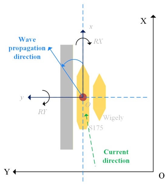
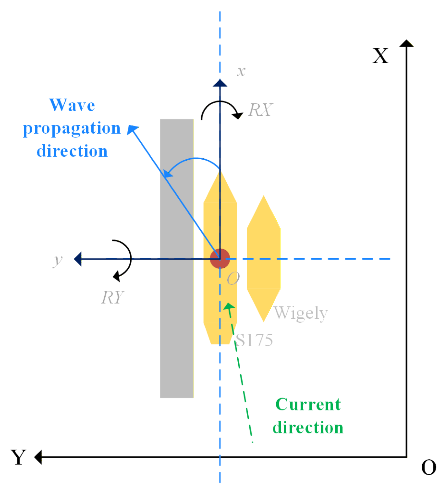
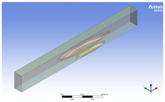
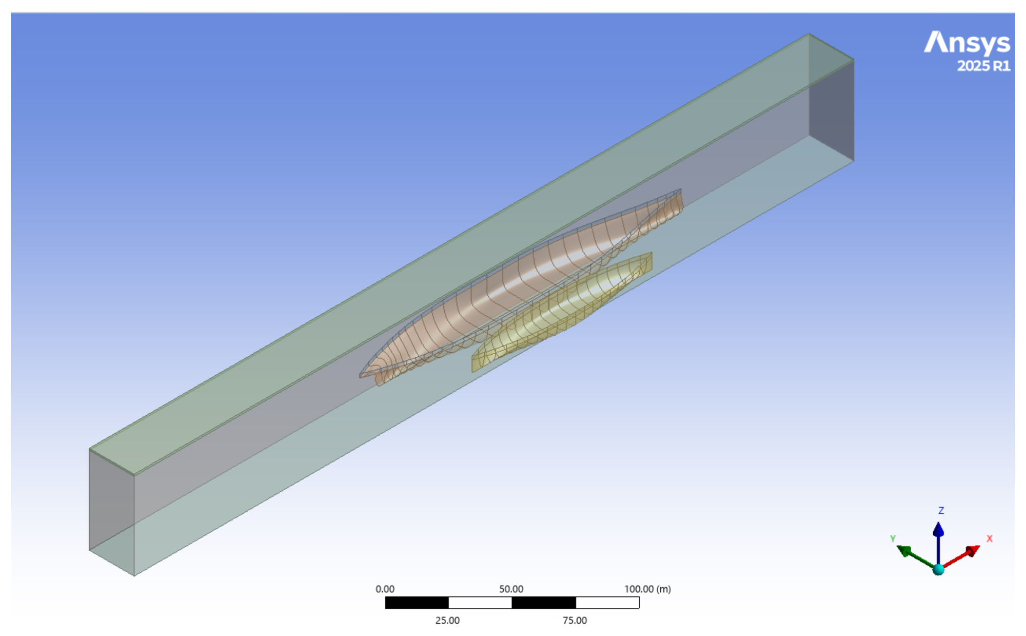
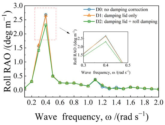
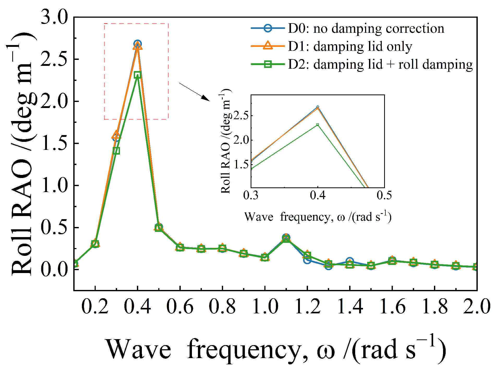
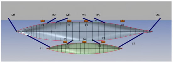
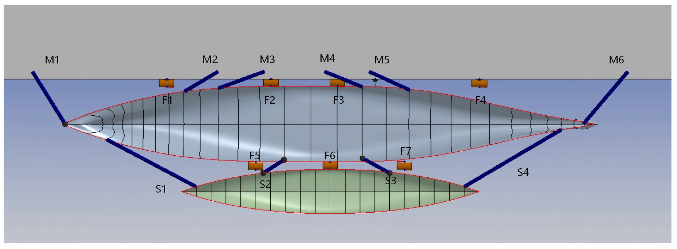
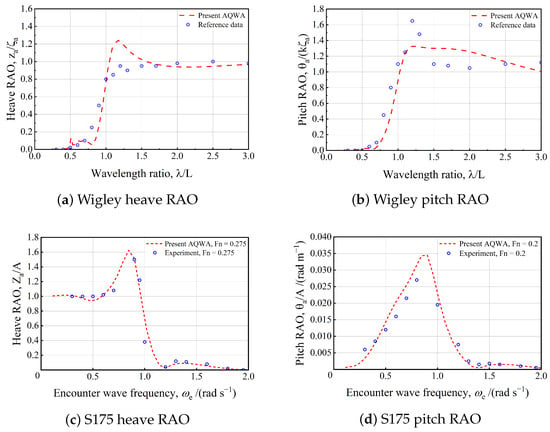
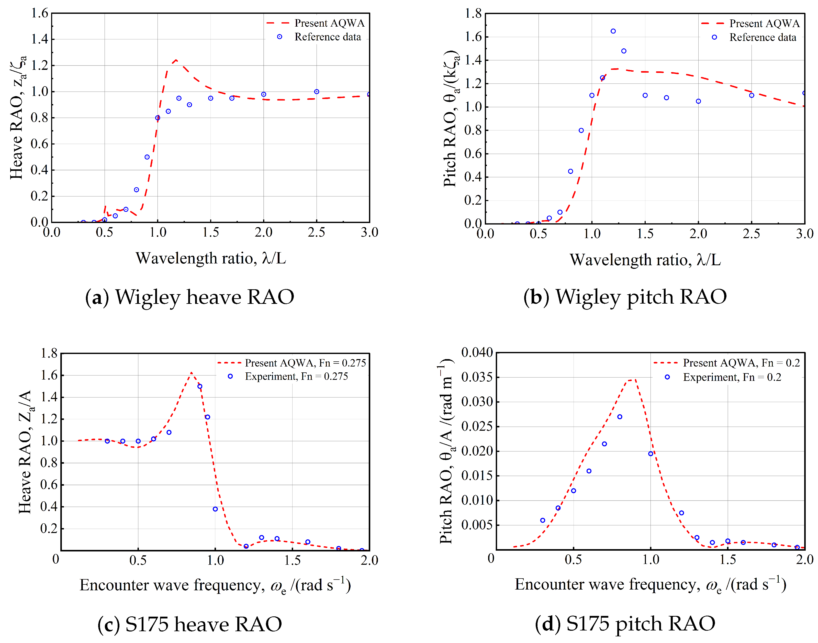
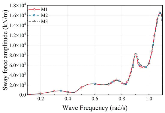
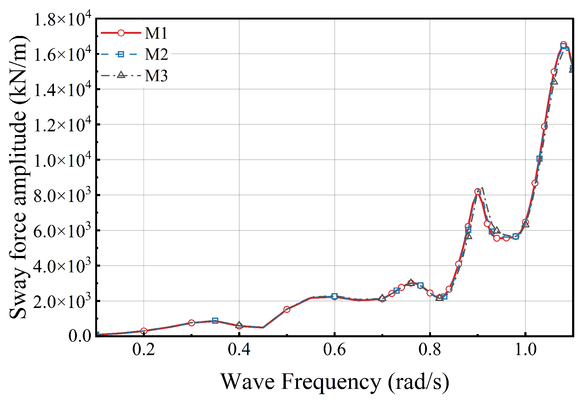
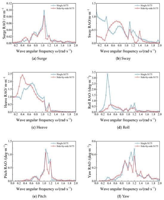
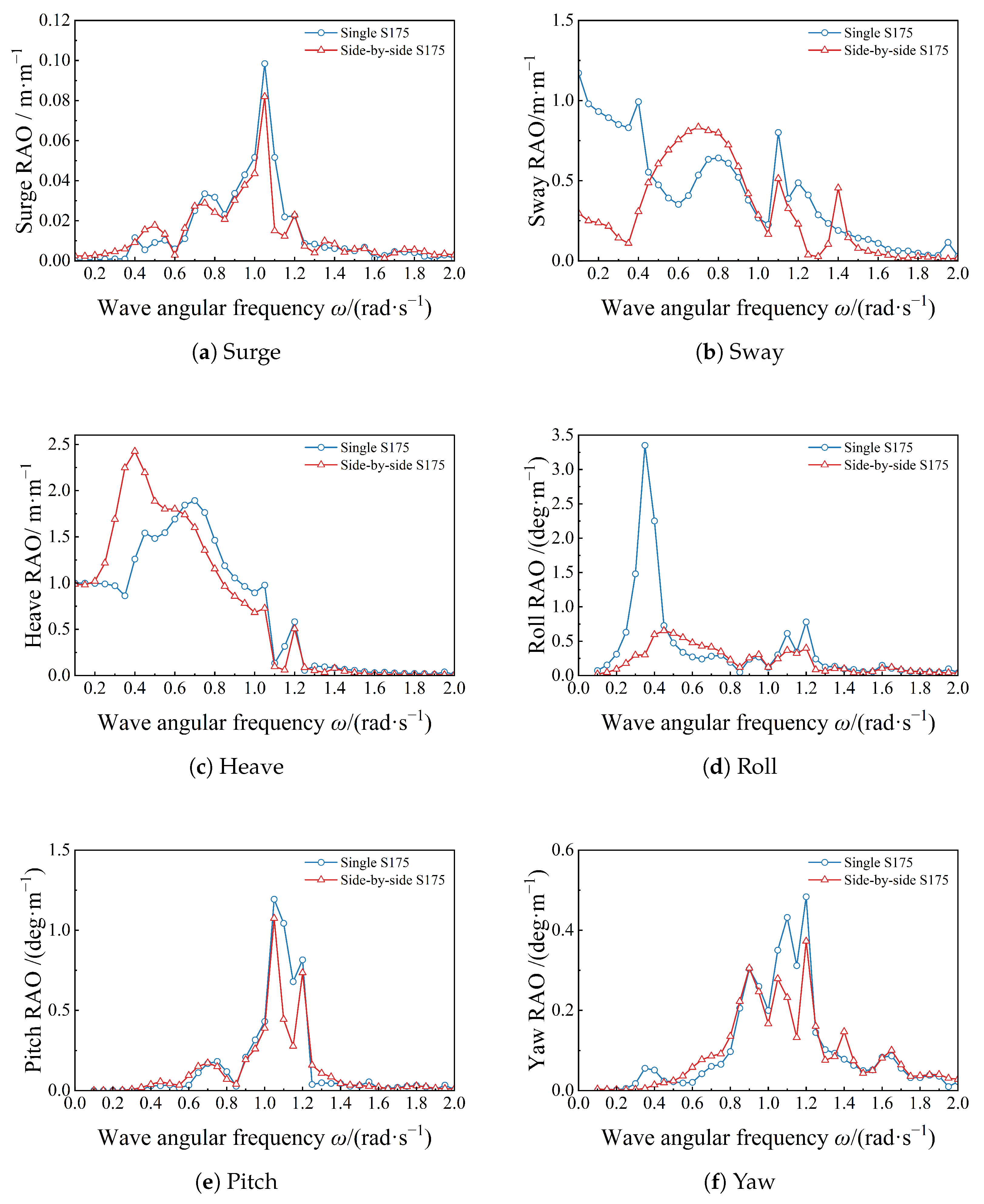
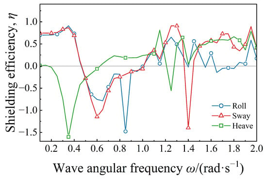
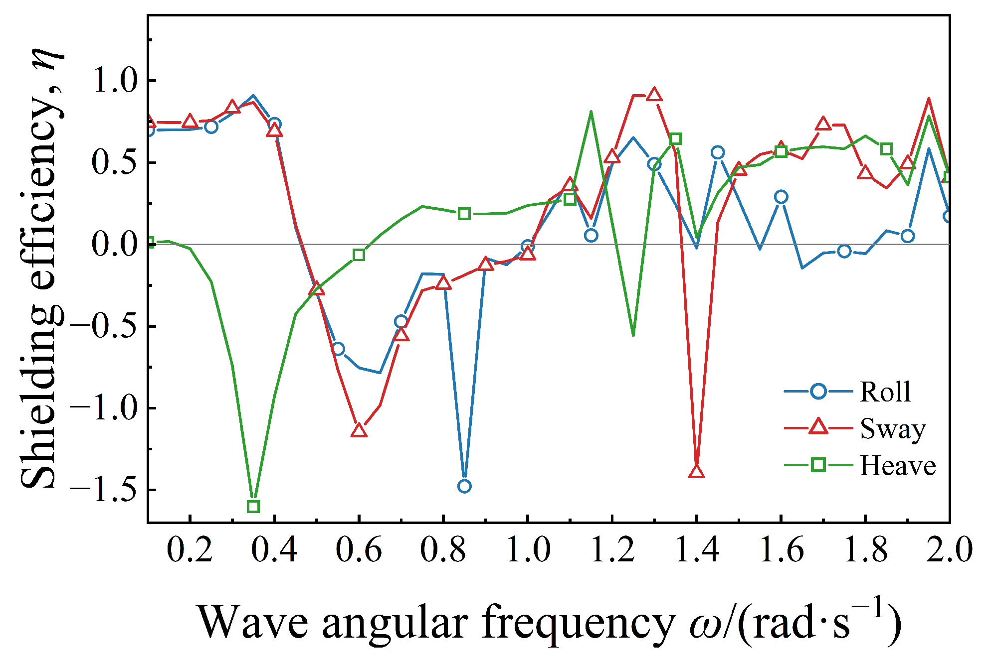
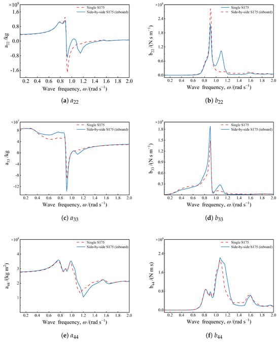
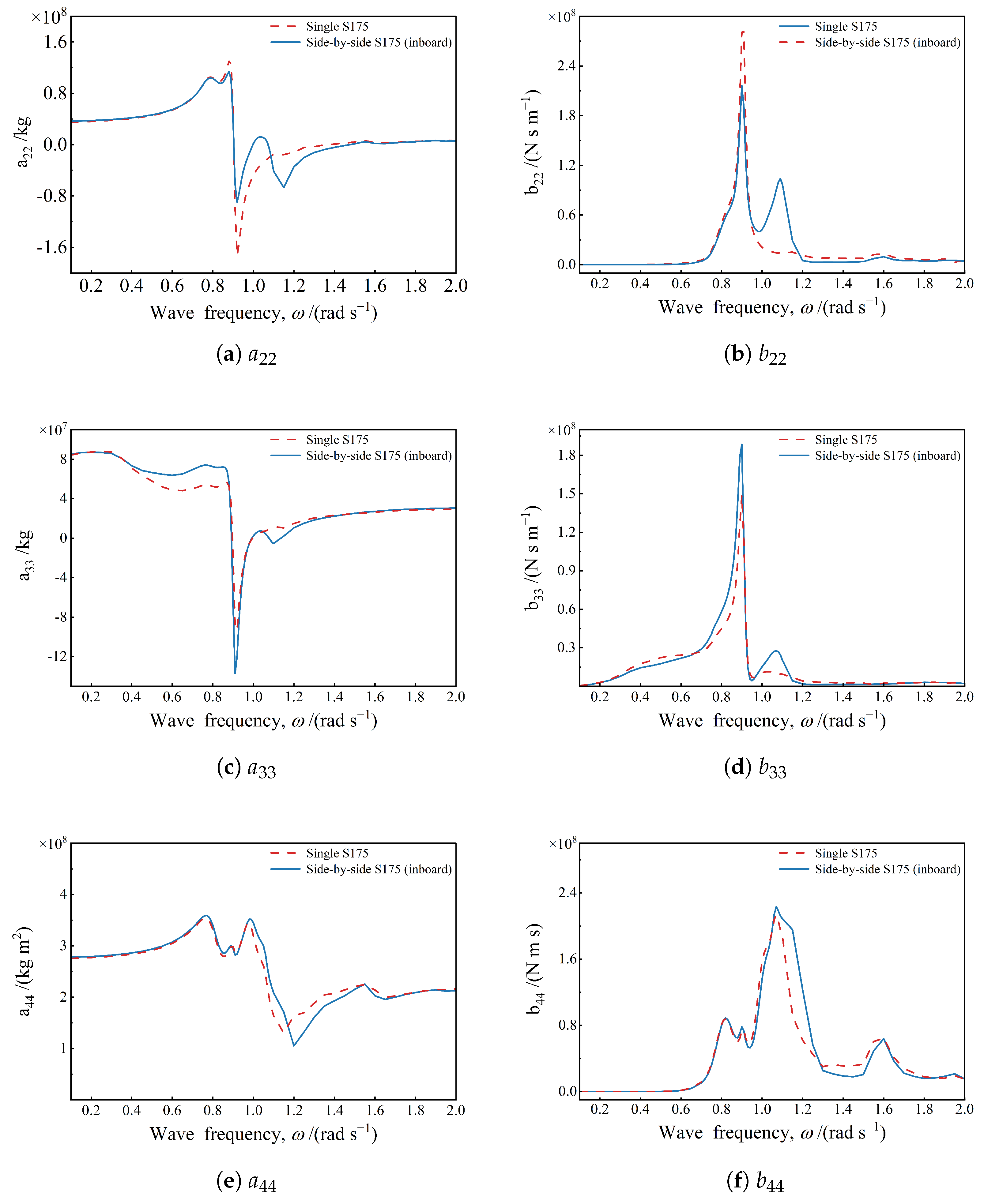
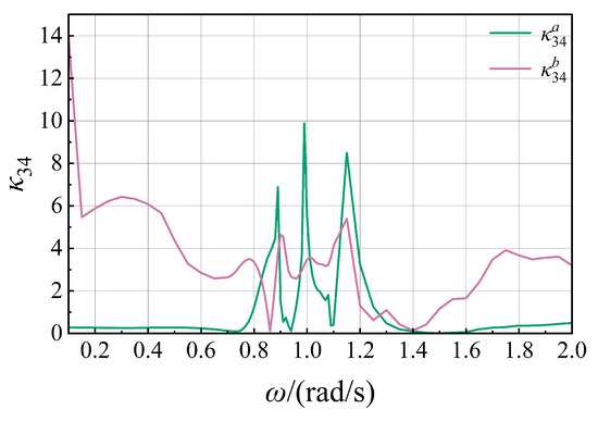
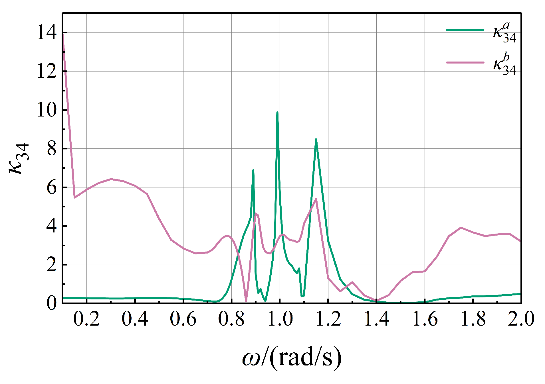
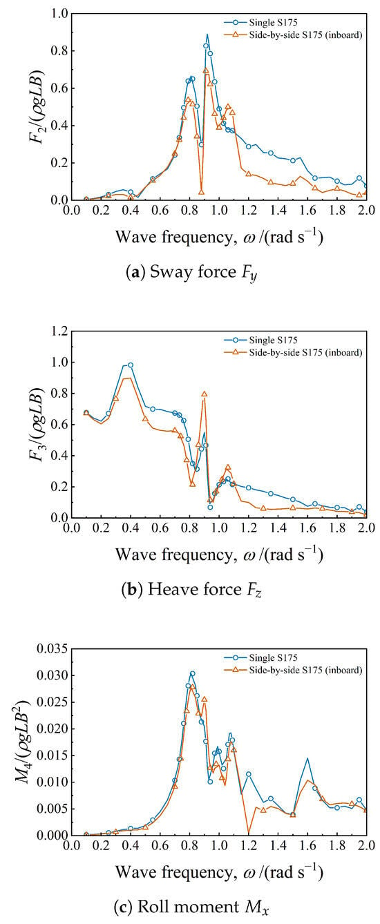
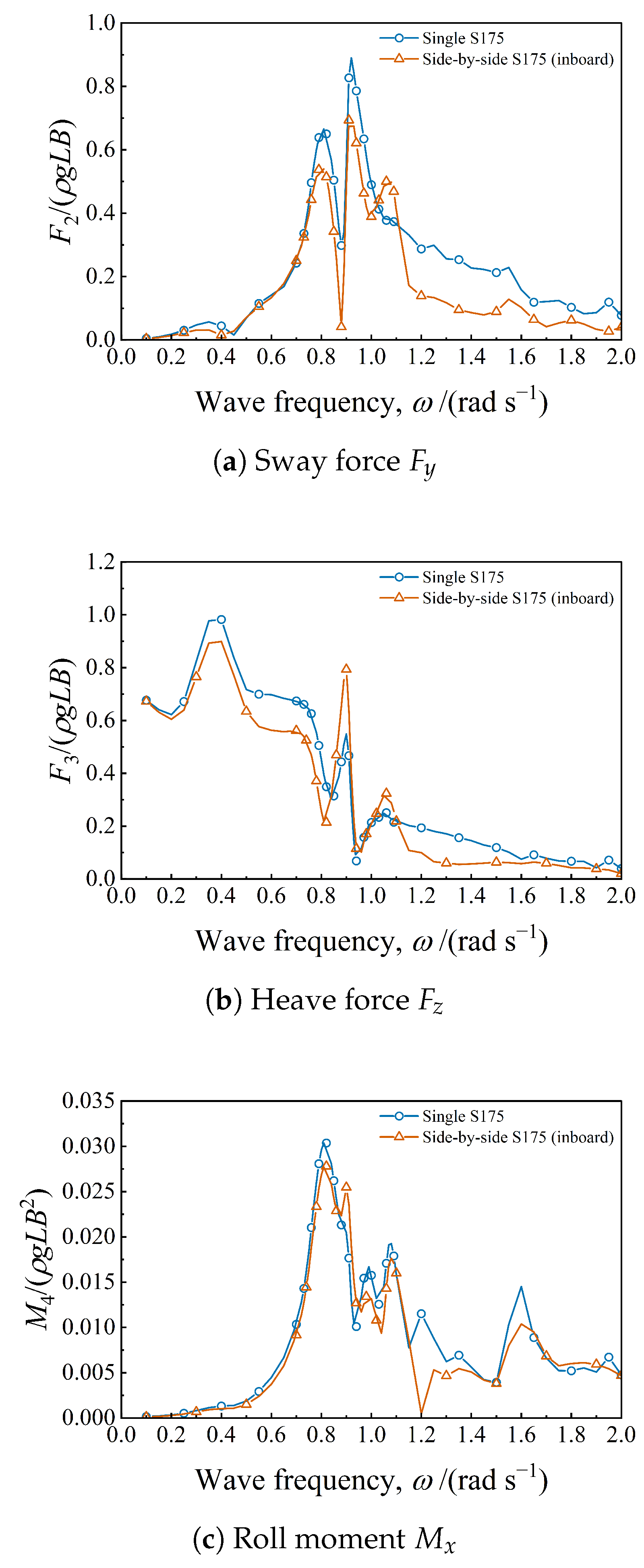
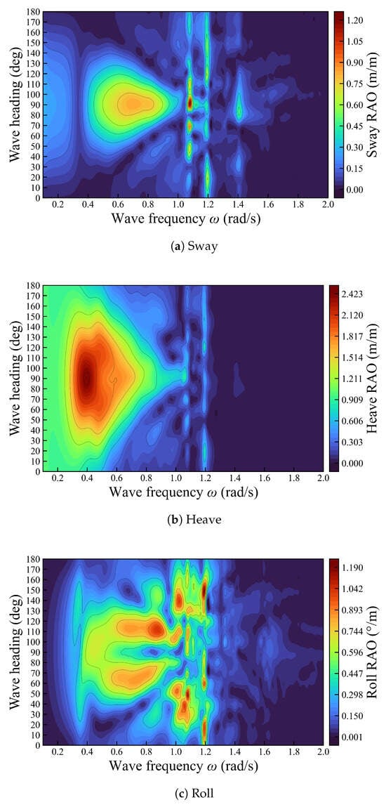
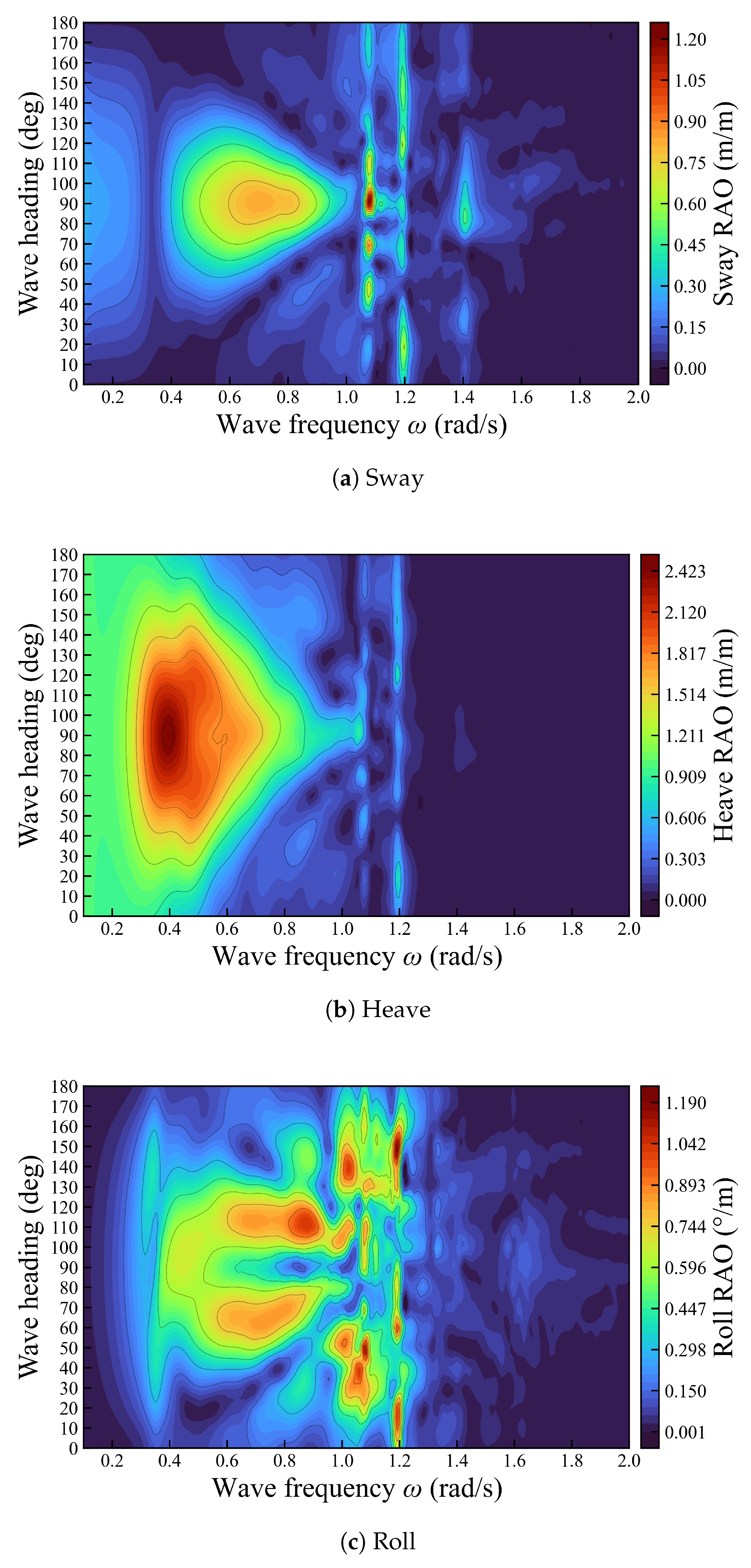
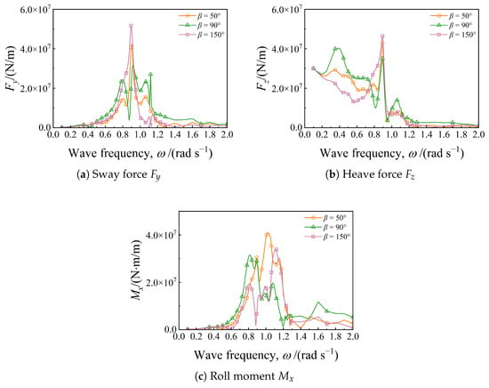
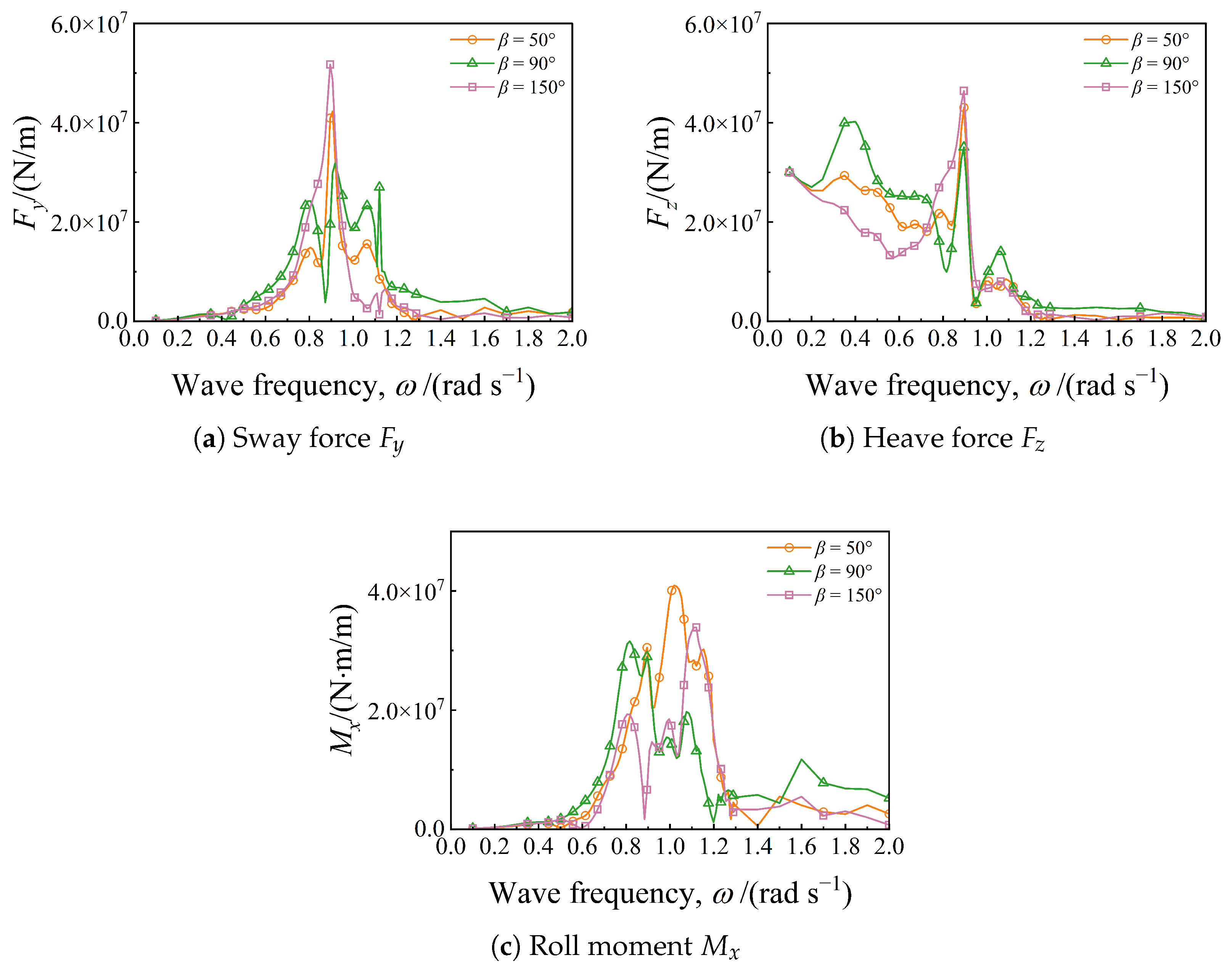
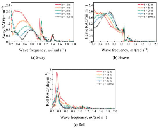
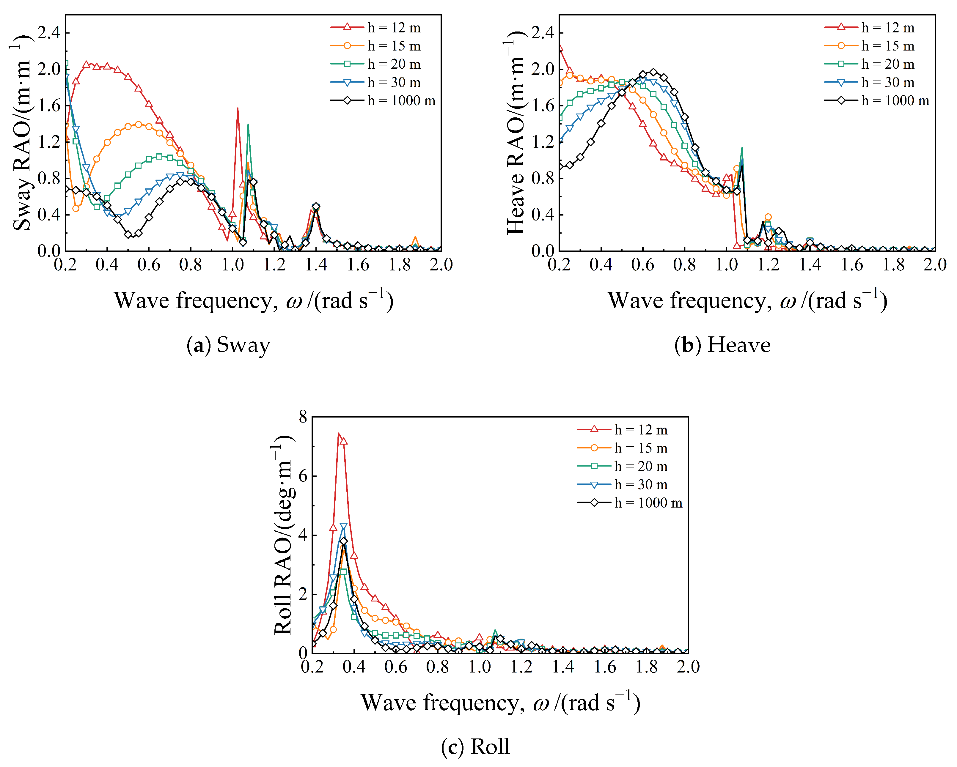
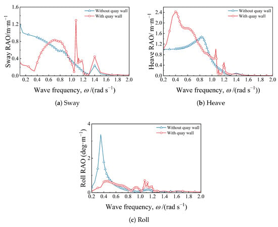
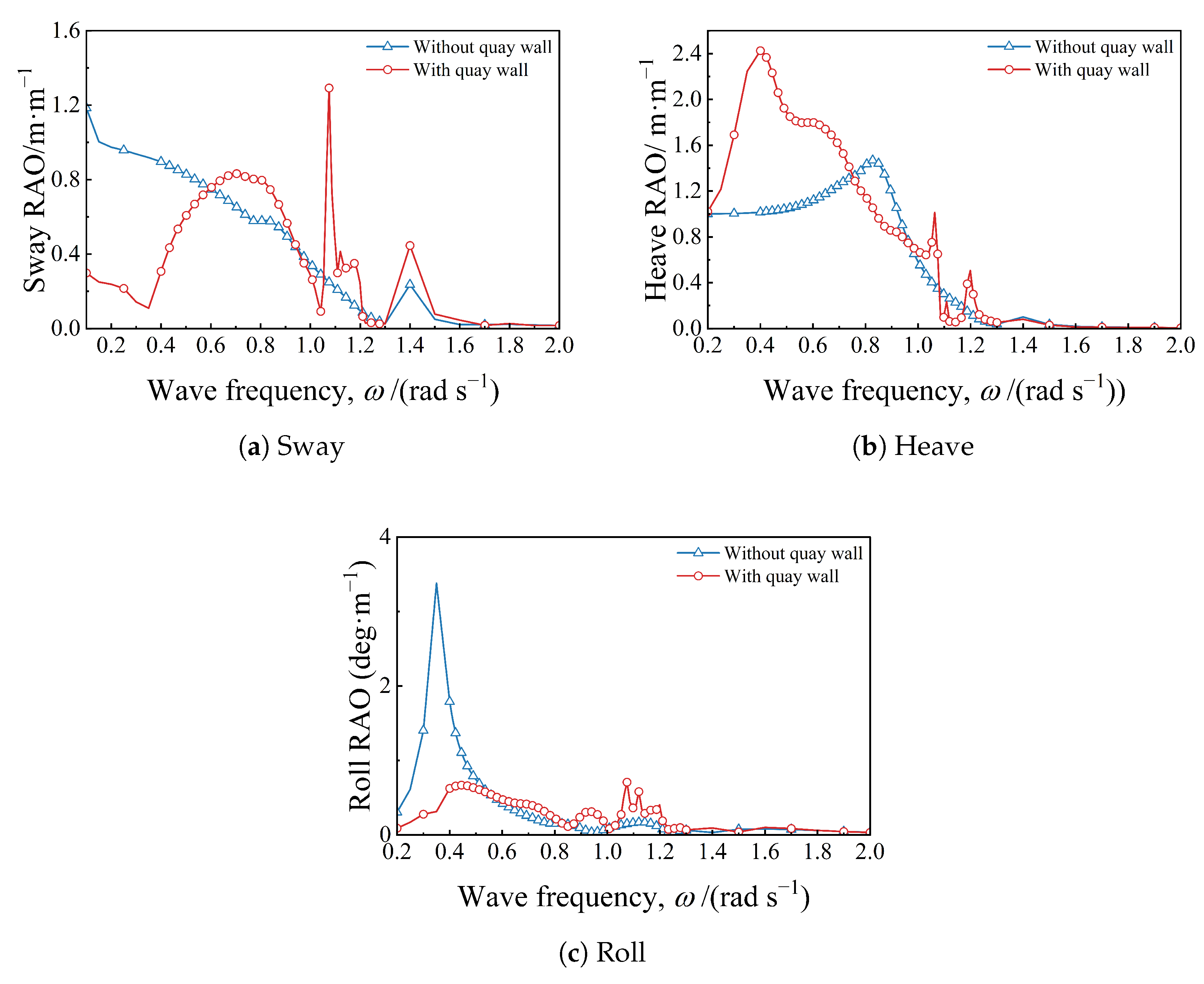
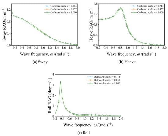
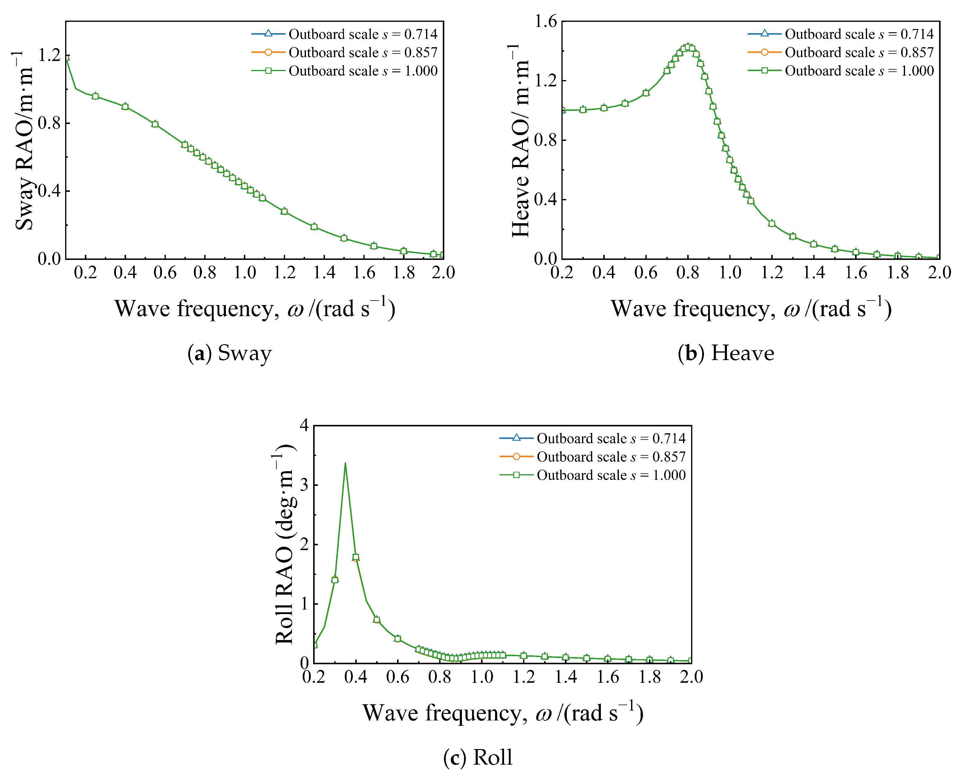
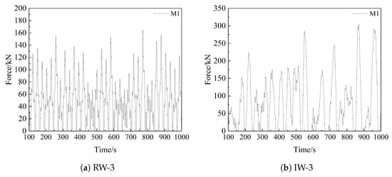
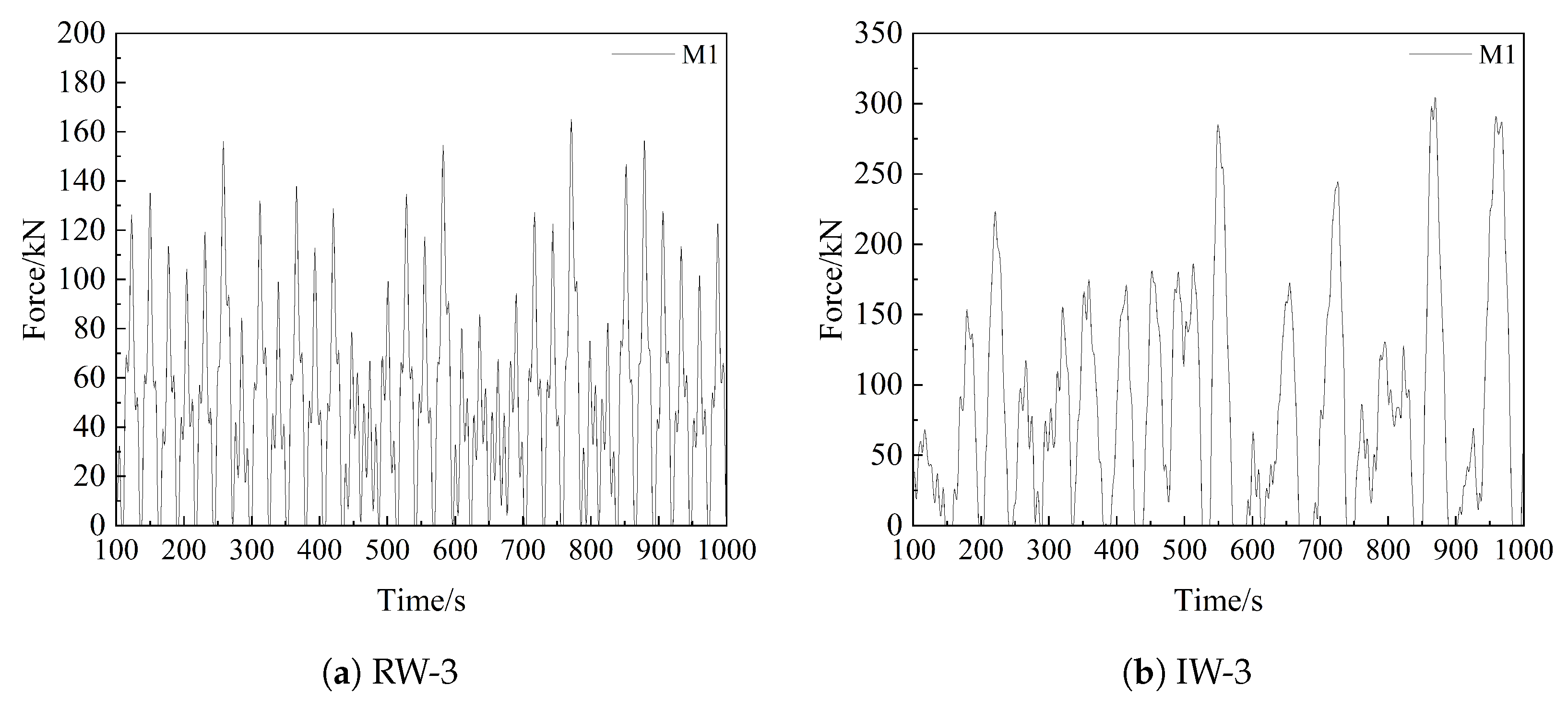
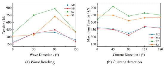
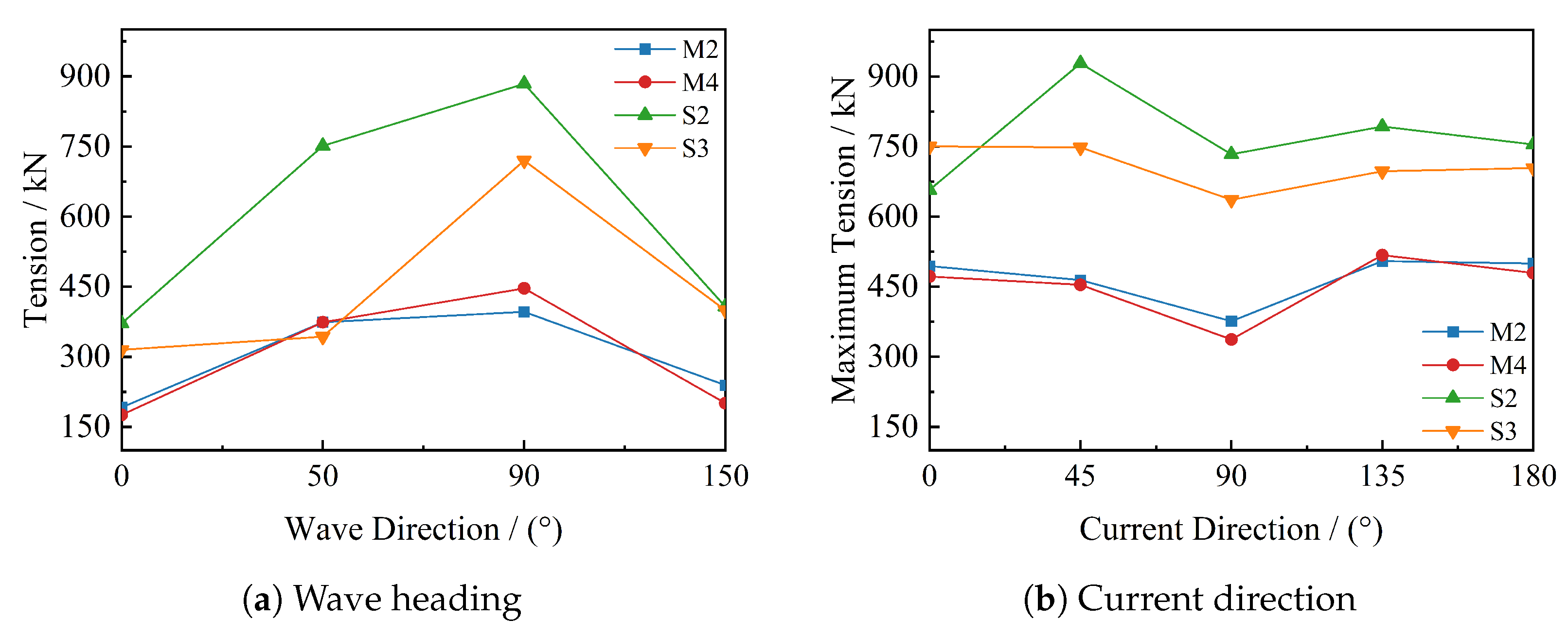

Disclaimer/Publisher’s Note: The statements, opinions and data contained in all publications are solely those of the individual author(s) and contributor(s) and not of MDPI and/or the editor(s). MDPI and/or the editor(s) disclaim responsibility for any injury to people or property resulting from any ideas, methods, instructions or products referred to in the content. |
© 2026 by the authors. Licensee MDPI, Basel, Switzerland. This article is an open access article distributed under the terms and conditions of the Creative Commons Attribution (CC BY) license.