Article

Coordinated Control of Automatic Drilling Feed and Heave Compensation for Offshore Hydraulic Hoisting Systems: A Co-Simulation Study

1
School of Mechanical Engineering, Chengdu Technological University, Chengdu 611730, China
2
CNPC Baoji Oilfield Machinery Co., Ltd., Baoji 721002, China
3
College of Intelligent Manufacturing, Qingdao University of Science & Technology, Qingdao 266042, China
4
National Engineering Research Center of Marine Geophysical Prospecting and Exploration and Development Equipment, China University of Petroleum (East China), Qingdao 266580, China
*
Author to whom correspondence should be addressed.
J. Mar. Sci. Eng. 2026, 14(13), 1184; https://doi.org/10.3390/jmse14131184
Submission received: 13 May 2026 / Revised: 18 June 2026 / Accepted: 19 June 2026 / Published: 28 June 2026
(This article belongs to the Section Ocean Engineering)

Abstract

Offshore drilling operations face the critical challenge of maintaining precise weight-on-bit (WOB) control during automatic drilling feed while subjected to vessel heave disturbances. This study investigates an integrated closed-circuit hydraulic cylinder lifting system that combines full-stroke drill string compensation with potential energy recovery capabilities, addressing the control coupling problem inherent in traditional split-design systems. A longitudinal vibration model of the drill string is established using lumped mass, stiffness, and damping principles incorporating the Rayleigh method. A co-simulation model implementing nested PID control logic is developed on the AMESim platform to evaluate automatic drilling feed performance under both passive and semi-active compensation modes. Simulation results demonstrate that the proposed integrated control strategy effectively mitigates bottom-hole WOB fluctuations, with top drive velocity accurately tracking set drilling feed rates (0.01–0.02 m/s) within a response time of approximately 10 s. The system maintains operational stability under sea conditions up to Grade 6 (heave wave height ≤ 4.578 m, period 14 s), beyond which accumulator piston limit-stroke collision risks emerge. These findings validate the feasibility of integrated hoisting-compensation design and establish quantitative operational limits, providing theoretical foundations for next-generation marine drilling systems targeting ultra-deepwater and natural gas hydrate exploitation.

1. Introduction

The escalating global energy demand and consequent expansion of offshore oil and gas exploration into ultra-deepwater and complex geological provinces have propelled marine drilling engineering into a new developmental paradigm [1,2]. According to recent assessments, deepwater and ultra-deepwater resources constitute an increasingly significant proportion of global hydrocarbon reserves, driving the need for advanced drilling technologies capable of operating in harsh marine environments [3,4]. Modern drilling vessels increasingly rely on integrated drilling packages equipped with efficient and reliable hoisting systems as core operational configurations [5]. Among these, hydraulic cylinder-based hoisting systems have emerged as the preferred alternative to conventional winch-based systems, offering significant advantages in vessel center-of-gravity control, installed power optimization, maintainability, and energy efficiency [6,7].
The integration of automatic drilling feed functionality with heave compensation represents a critical technological frontier for precision offshore drilling operations. Automatic drilling feed, which governs the rate of penetration (ROP) through precise weight-on-bit (WOB) control, directly influences drilling efficiency, wellbore quality, and operational safety [8,9]. However, the marine environment introduces complex disturbances through vessel heave motion induced by wave action, which couples with drill string dynamics to exacerbate WOB fluctuations [10,11]. Greenfield and Lubinski [12] established foundational understanding of bumper sub behavior in floating vessel drilling, demonstrating that the vertical motion at the bottom of the drill string may be appreciably greater than vessel heave due to dynamic response amplification, with motion ratios reaching 1.5–2 for drill strings of 16,000 ft length.
Traditional offshore drilling installations adopt a split-design architecture wherein the hoisting system and drill string compensation device operate as independent subsystems [13]. This decoupled approach fails to account for the dynamic interaction between drilling feed control and compensation actions, resulting in excessive bottom-hole pressure variations that compromise drilling accuracy and stability [14,15]. Huang et al. [16] proposed a semi-active drawworks heave compensation system achieving decoupling control through internal model PID robust displacement control, demonstrating compensation rates exceeding 90% through both simulation and experimental validation. Their work established the feasibility of dual closed-loop control schemes for decoupling heave compensation from automatic bit feed motions. However, the specific challenge of coordinated control during simultaneous compensation and drilling feed operations under varying sea states remained incompletely addressed.
The longitudinal vibration characteristics of drill strings during heave-compensated operations introduce additional complexity that must be incorporated into system modeling. Aarsnes and Aamo [17] provided the theoretical foundations for understanding drill string dynamic behavior by addressing self-excited vibrations through infinite-dimensional modeling. Niedzwecki and Thampi [6] investigated heave-compensated response of long multi-segment drill strings, establishing relationships between vessel motion and drill string displacement amplification. These modeling frameworks, combined with industry standards [18], enable realistic simulation of drill string dynamics under marine operating conditions.
Recent advances in hydraulic system design have demonstrated the potential for functional integration to address these limitations. Closed-circuit hydraulic architectures, combined with energy storage and recovery units, enable simultaneous realization of hoisting, compensation, and potential energy recuperation functions [19,20]. Li et al. [21,22] conducted systematic AMESim-based simulation studies on closed hydraulic cylinder lifting systems, elucidating three key technologies: load lifting and lowering fluid control, gravitational potential energy recovery and release, and integrated drill string compensation. Their results demonstrated that semi-active compensation offers the best adaptability to varying sea states without requiring additional compensation devices. However, no relevant research has been conducted on the automatic drilling feed condition under drill string compensation. The RamRig series by Aker MH exemplifies this integrated approach in commercial applications, utilizing closed hydraulic circuits to support both passive and semi-active compensation modes through coordinated control of relief valve unloading pressures [23].
The control coupling between automatic drilling feed and heave compensation presents a fundamental challenge requiring coordinated control strategies. Zhang et al. [24] investigated electro-hydraulic lifting system control strategies through AMESim-MATLAB co-simulation, establishing foundations for multi-loop control architectures. Yao et al. [25] developed novel position control with online parameter estimation for electro-hydraulic servo systems, achieving improved tracking accuracy through adaptive techniques. Furthermore, recent advancements in marine environments have demonstrated that integrating Model Predictive Control (MPC) with adaptive constraints can significantly enhance the robustness and tracking precision of underwater systems against external disturbances [26]. For marine applications specifically, Hatleskog and Dunnigan [27] explored heave compensation dynamics within the context of deep-water non-contact operations. By utilizing simulation studies, they established a clearer understanding of the system’s operational boundaries. Godhavn [28] examined control requirements for automatic managed pressure drilling in harsh environments, highlighting the need for integrated approaches to handle environmental disturbances.
Energy efficiency considerations further motivate integrated system development. Jun et al. [29] proposed potential energy recovery methods based on alternate hydraulic cylinder utilization, while Qiao et al. [30] developed electro–hydraulic compound driving systems with regeneration capabilities for lifting applications. Triet and Ahn [31] provided comparative assessment of energy recovery systems for hydraulic excavators, demonstrating significant efficiency improvements through regenerative architectures. The combination of closed hydraulic circuits with energy storage inverter units offers the potential to recover and reuse lowering potential energy, reducing overall installed power requirements [32]. However, the interaction between energy recovery functionality and drilling feed control performance has received limited attention in existing literature. Sea state adaptability represents another critical dimension for offshore drilling systems. The heave response characteristics of floating platforms vary significantly with wave height and period, imposing operational limits on drilling activities [33,34]. Zhang et al. [35] analyzed hull heave motion parameters under varying sea conditions, establishing quantitative relationships between sea state grades and vessel motion characteristics. Understanding how these environmental disturbances interact with integrated hoisting-compensation systems during automatic drilling feed operations is essential for establishing safe operating envelopes. Liu et al. [36] reviewed the current status and development strategies of deep-sea drilling heave compensation devices in China, identifying key technological gaps and future research directions.
Despite significant advances in individual technological domains—including hydraulic cylinder positioning control [37], compensation system design [38], and energy recovery or layout optimization [39,40,41]—a pronounced research gap persists regarding the coordinated control mechanism between hoisting, compensation, and automated drilling functions. Systematic simulation analysis of automatic drilling feed performance under complex sea states remains scarce, limiting comprehensive performance improvement of cylinder hoisting systems for demanding offshore applications. Furthermore, the quantitative thresholds for sea state operability under integrated control architectures have not been rigorously established. The novel CHS900/36PIU system developed by CNPC Baoji Oilfield Machinery Co., Ltd. represents a significant step toward addressing these challenges, integrating full-stroke drill string compensation with supercapacitor-based energy recovery [42].
This study addresses these gaps by investigating a novel closed-circuit hydraulic cylinder lifting system that integrates load hoisting with the compensation capabilities of the drill string through unified hydraulic architecture and nested PID control logic. The core innovation of this work is not a single element but rather a systematic combination of the integrated hydraulic architecture, the coordinated control logic, the automatic drilling feed strategy, and the sea state operability analysis. Building upon preliminary work by Lei et al. [43] on cylinder lifting system design, we develop a comprehensive simulation model incorporating drill string longitudinal vibration dynamics based on lumped mass, stiffness, and damping principles. It should be noted that this work is primarily based on co-simulation analysis; prototype field validation and formal frequency-domain stability analysis (including gain margin and phase margin under periodic disturbances) of the nested PID controller will be conducted in subsequent studies. The specific objectives are: (1) to establish a co-simulation framework on the AMESim platform incorporating nested PID control for coordinated compensation and drilling feed; (2) to evaluate automatic drilling feed performance under both passive and semi-active compensation modes; (3) to quantify the impact of passive and semi-active compensation activation on bottom-hole WOB fluctuation reduction; and (4) to determine sea state operability limits for the integrated system under representative drilling conditions. The findings provide theoretical foundations and technical references for next-generation marine drilling hoisting system development targeting ultra-deepwater and natural gas hydrate exploitation scenarios.
The subsequent framework of this study is categorized as follows: Section 2 introduces the integrated closed-circuit hydraulic cylinder lifting system architecture, detailing the working principles of both the drill string compensation mechanism and the automatic drilling feed function. Section 3 establishes the drill string’s longitudinal vibration model, built upon lumped mass, stiffness, and damping principles, and presents the development of the AMESim co-simulation model incorporating nested PID control logic for coordinated operation. Section 4 presents and discusses the simulation results, including the evaluation of automatic drilling feed performance under passive and semi-active compensation modes, the quantitative comparison of weight-on-bit (WOB) fluctuation reduction, and the determination of sea state operability limits. Section 5 concludes with key findings, engineering implications for next-generation offshore drilling systems, and future research directions.

2. System and Mechanism Overview

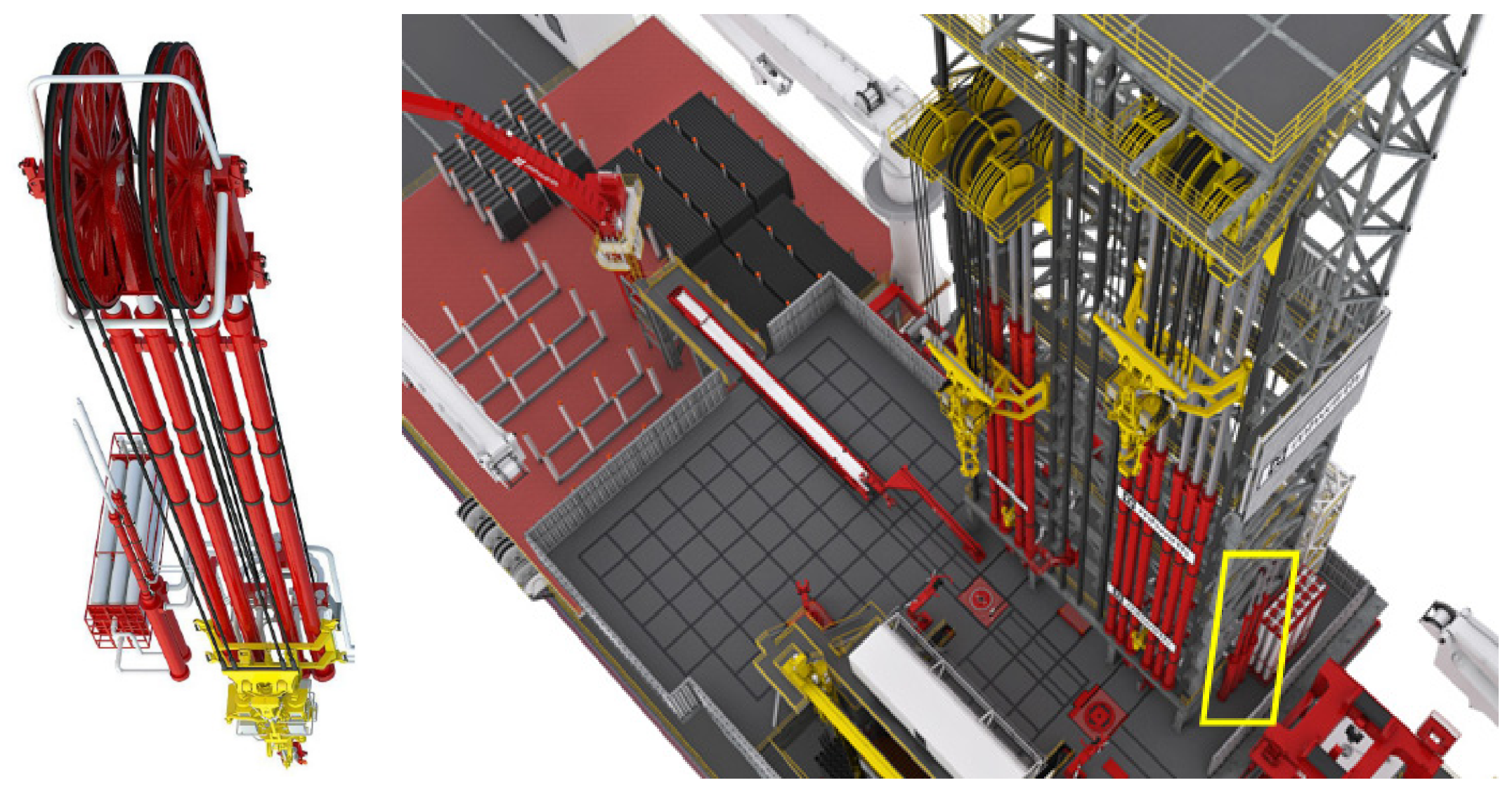
Aker MH’s RamRig series is incorporated into an integrated architecture for lifting and drill string compensation and is designed based on a closed hydraulic circuit. It supports two modes: passive compensation and semi-active compensation, as shown in Figure 1. The core principle is that after the wave compensation is started, the unloading pressure of the relief valve in the C loop is closed-loop adjusted, so that the lifting hydraulic cylinder can slowly retract while compensating the wave motion, so as to achieve constant-speed drilling.
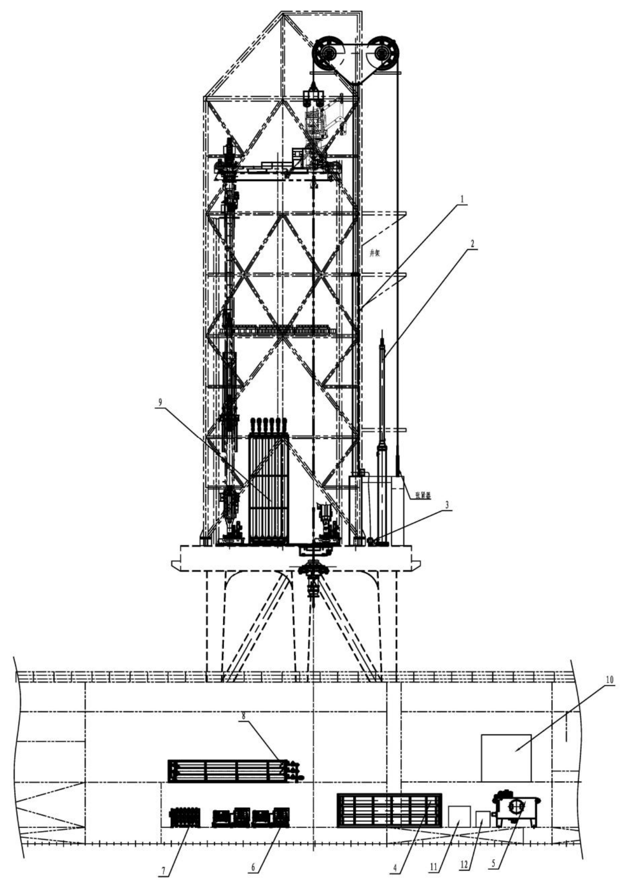
To address the limitations of conventional hydraulic cylinder lifting systems—such as low functional integration, significant fluctuations in weight-on-bit caused by vessel heave interference during automatic marine drilling, and substantial energy loss from uncontrolled drill string lowering—Baoji Petroleum Machinery Co., Ltd. has developed a novel CHS900/36PIU hydraulic cylinder lifting system, as shown in Figure 2.This system integrates a closed hydraulic circuit, full-stroke drill string compensation, and supercapacitor-based energy recovery. As the core enabler of precise and efficient drilling, investigating the automatic drilling performance of this system under various operating conditions is of critical importance. On one hand, by replacing traditional manual operations, the system enables accurate control of weight-on-bit and rate of penetration, directly influencing drilling efficiency, wellbore quality, and operational safety. On the other hand, to enhance its environmental adaptability in complex marine environments, the system must address the coupling effects between drilling control and drill string compensation, thereby mitigating the impact of vessel heave on drilling accuracy.
Figure 2. Layout of CHS900/36PIU hydraulic cylinder lifting and compensation system. 1—top pulley assembly, 2—lower support frame, 3—lifting hydraulic cylinder assembly, 4—compensation accumulator, 5—steel wire rope assembly, 6—accumulator valve group, 7—hydraulic station, 8—nitrogen compressor, 9—main gas valve control skid, 10—pressure boost and reduction control skid, 11—compensation nitrogen cylinder, Bank12—hydraulic cylinder control valve group.
Jmse 14 01184 g002
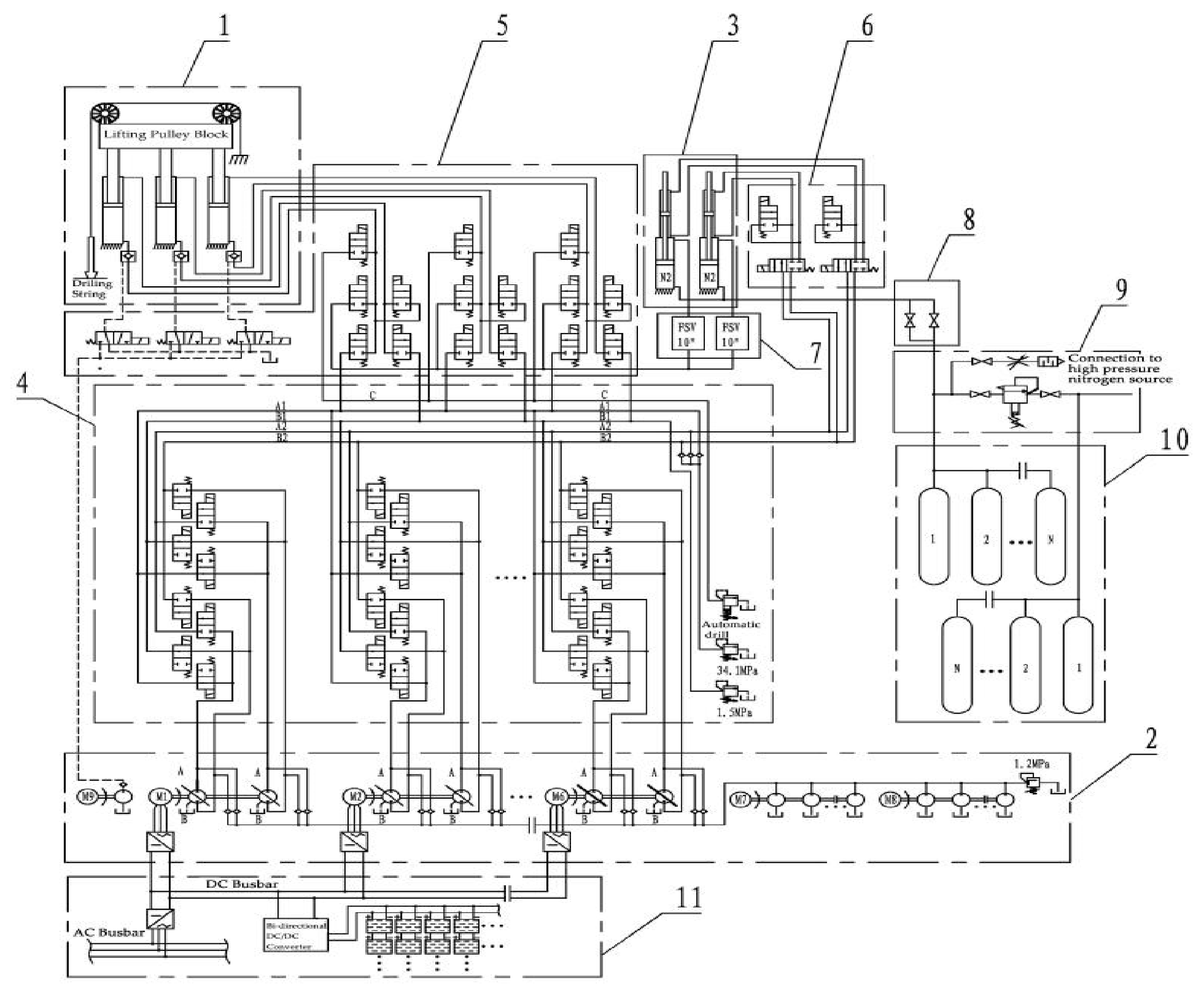
This study uses a certain type of cylinder hoisting system developed by CNPC Baoji Oilfield Machinery Co., Ltd. as the research object, and its structural principle is detailed in Figure 3. The cylinder hoisting system adopts 3 hoisting cylinders to drive the top pulley block and steel wire ropes for vertical load translation, and the hoisting cylinders are double-acting cylinders. In order to supply oil to the system, the hydraulic station operates an array of main pumps, all of which are configured as closed-loop variable displacement pumps. The pressure in the working chamber of the hoisting cylinders is adjusted through pump control to realize load lifting and lowering, and a make-up oil circuit is designed. The oil circuit switching valve manifold allows for the independent shutdown of each line; thereby guaranteeing that an isolated breakdown of one main pump will not halt overall system operations. The cylinder valve group can switch the hoisting cylinders between double-acting cylinders and plunger cylinders and also connect the hoisting oil circuit to the compensation accumulator. By combining the hoisting cylinders, compensation accumulators, and high-pressure gas cylinder groups, the full-stroke drill string heave compensation capabilities of the hoisting cylinders for the drill string can be achieved. Semi-active compensation is initiated via the accumulator valve group, where the switching valve group routes main pump discharge to the accumulator. By adjusting the closed-loop pump’s displacement, the system ensures accurate piston tracking, thereby mitigating the parasitic inertia and frictional effects of passive compensation. To enhance efficiency, an integrated inverter unit—incorporating supercapacitors and variable-frequency drives—is employed for energy regeneration, capturing and recycling gravitational potential energy from the descending load.

2.1. Mechanistic Analysis of Drill String Compensation

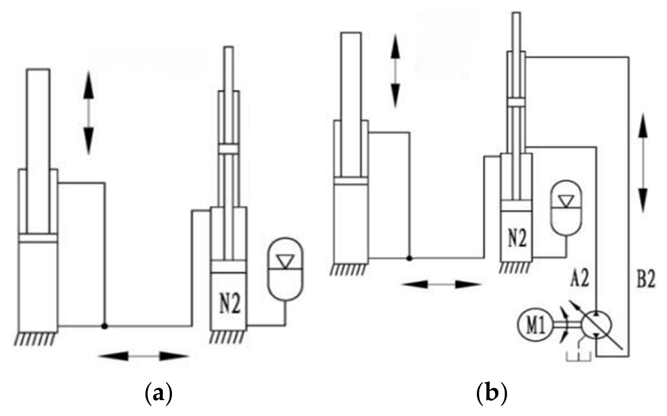
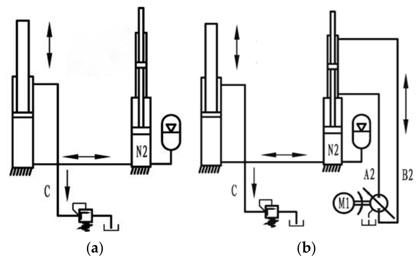
Drill string compensation is primarily executed by the lifting cylinder actuator, which functions in tandem with a compensation accumulator and cylinder assembly to regulate energy storage and discharge throughout the cycle. Structurally, the accumulator unit features a lower accumulator paired with an upper constant-speed cylinder. This specific architecture enables the lifting setup to deliver two distinct modes: passive and semi-active compensation, as shown in Figure 4.
To initiate the drill string compensation, the hoisting cylinder must first operate in a plunger cylinder mode. This is achieved by interconnecting its piston and rod chambers, and subsequently linking the cylinder to the compensation accumulator. Once the gas cylinder pressure is adjusted to a suitable value, a connection is established between the two rod chambers of the compensation accumulator’s constant-speed cylinder. Consequently, the constant-speed cylinder is brought into a follow-up state. Under the combined drive of the gas cylinder and accumulator, the hoisting cylinder extends and retracts with the vessel’s heave motion, maintaining a constant bottom-hole drilling pressure and realizing the passive compensation function. In cases of severe sea conditions, high-precision drilling, and lowering of subsea equipment, a direct connection is established between the two rod chambers of the constant-speed cylinder, which are linked to a closed-loop pump group. While passive compensation is activated, the closed-loop pump functions to actively control the displacement of the constant-speed cylinder, offsetting the inherent friction and inertia of passive compensation, improving compensation accuracy, and thereby executing semi-active compensation of the drill string.

2.2. Automatic Drilling Mechanism Analysis

Automatic drilling is the key function to reduce the labor intensity of drillers. The system is designed for offshore drilling. Unlike onshore drilling, automatic drilling is usually used when wave compensation starts. The system can be divided into two modes: passive compensation automatic drilling and semi-active compensation automatic drilling, as shown in Figure 5. The basic principles of the two drilling modes are the same: when the wave is compensated, the C-loop relief valve is opened, and the unloading pressure of the relief valve is adjusted by a small-scale closed-loop control, so that the lifting cylinder can slowly retract while compensating the wave motion, so as to achieve automatic drilling.

3. Formulation and Analysis of the Model

3.1. Analysis of the Drill String’s Longitudinal Vibration Model

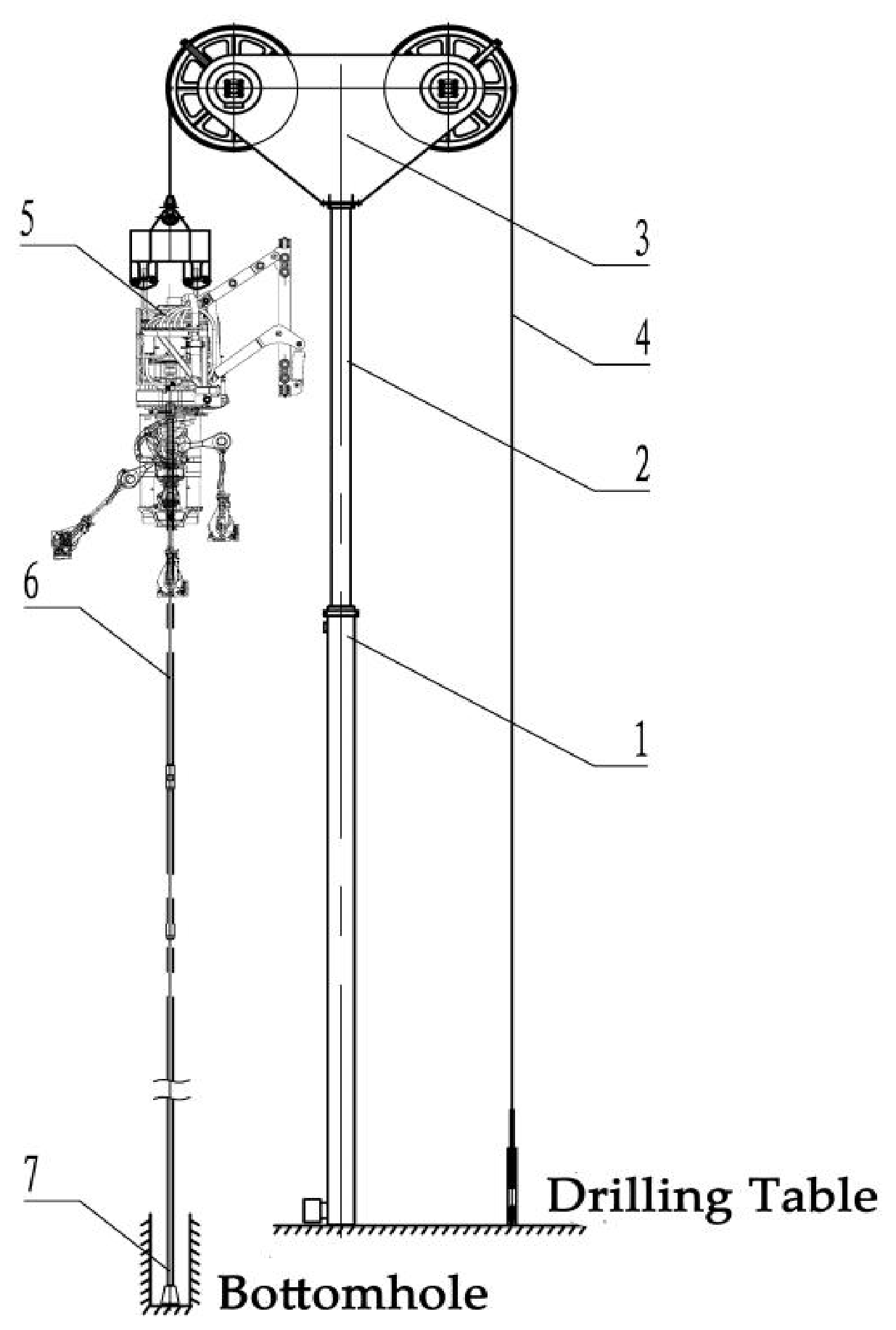
The simplified cylinder lifting system is illustrated in Figure 6. By disregarding the impact of bottom-hole drill bit vibration, the drill string is treated as a slender rod. Subjected to excitation displacement, the drill pipe’s dynamic response is modeled as a single-DOF (degree-of-freedom) system incorporating damping and external forcing. To facilitate this research, horizontal movements of the drill pipe are intentionally omitted.
During compensation, the hoisting cylinders drive the top pulley block to transmit the hoisting force via steel wire ropes. This force is progressively transferred downward along the drill string, resulting in a tensile state above the neutral point and a compressive state below it. At the bottom of the well, the bottom-hole assembly experiences the reactive force exerted by the formation. The hydro-pneumatic spring, formed by the hoisting cylinders and compensation accumulators, extends and retracts in response to the heave motion of the platform, causing the drill pipe to undergo longitudinal heave motion. The inherent axial compliance of the drill string buffers force fluctuations, ensuring stable WOB (weight-on-bit) at the bottom hole. Based on this mechanism, the following model establishment criteria can be derived:
(1)
The simplified drill string model presented here is sufficient to capture the trend of weight-on-bit and the system’s dynamic response. The neglect of lateral motion, bit vibration, and nonlinear wellbore coupling is first aimed at reducing the overall simulation complexity, and second, a more detailed drill string model is reserved for precise bottom-hole WOB analysis. Accordingly, we adopt the following principle of mass concentration: by treating the tubular string as a flexible continuum, its inertial mass and stationary hardware loads (e.g., top drive) are aggregated at the traveling block interface. Applying the Rayleigh method, the string’s equivalent concentrated mass equals 1/3 of its total weight ( M d r i l l ). Consequently, the final lumped mass MC at the block is:
M C = 1 3 · M d r i l l + M d r i l l p + M t p
where M d r i l l represents the inertial mass associated with the drill string’s tension-bearing portion. This parameter is typically determined by deducting the preset drilling pressure from the gross weight of the complete drill pipe. Excluding the horizontal section, the overall weight of the drill string is calculated by multiplying the weight of the 5-1/2 inch drill pipe (36.78 kg/m) by the vertical drilling depth. M t p signifies the top drive weight, specified as 38.55 t.
(2)
Principle of stiffness concentration: The structural stiffness of the entire elastic drill string is lumped into a single equivalent coefficient, K 2 . Furthermore, the heave compensator is represented by a zero-mass spring with a rigidity coefficient of K 1 .
The stiffness K1 of the hydro-pneumatic spring is determined by the following formula:
K 1 = n · A p 2 p 0 · V 0 n V 0 A p x n + 1
where V0 (m3) stands for the mean gas volume within the hydro-pneumatic spring, and p0(Pa) indicates the corresponding accumulator pressure at this volume. The parameter Ap (m2) signifies the accumulator’s functional piston surface area, n represents the polytropic index of the working gas, and x represents the piston displacement. Furthermore, K1 is determined through software simulation and represents the piston displacement, whereas K2 represents the integrated elastic rigidity of the string assembly, formulated according to the relationship below:
K 2 = 1 1 K W + 1 K D + 1 K F
where KW denotes the rigidity of the hoisting cable linkage situated between the upper pulley assembly and the top drive unit, assigned a constant value of 1960 kN/m; KD represents the integrated elastic rigidity of the tubular string, which scales with the total axial depth, as determined by the following relationship:
K D = E · A L
where L stands for the vertical length of the drill string, E indicates the elastic modulus of the drill string material, evaluated at 2.06 × 10¹¹ Pa. The parameter A defines the drill string’s cross-sectional area, specified as 0.004277 m2 based on the 5-1/2 inch drill pipe (with a diameter of 139.7 mm). KF dictates the formation contact stiffness, fixed at 1000 kN/m.
(3)
Principle of damping concentration: The damping coefficient with drill string compensation is designated as C1 and obtained through software modeling. Meanwhile, C2 represents the frictional damping coefficient of the drill string within the wellbore. Energy dissipation occurs due to the relative motion between the drill string and the drilling fluid, a phenomenon driven by the fluid’s viscosity and pressure. The corresponding calculation is given by:
C 2 = π 8 · C N · C a · ρ d · D · v d · L
where CN signifies the friction coefficient, which is derived from the empirical data of specific drilling fluids (assigned as 0.1 for water-based drilling fluid in this study). Ca denotes the added mass coefficient, fixed at 1 for a cylinder submerged in fluid. The parameter ρ d represents the mud density, specified as 1200 kg/m3; furthermore, D stands for the drill string diameter (0.1397 m), while vd is the mud flow velocity, set at 0.3 m/s.
(4)
Assumptions of boundary conditions: During drilling, the drill collars and bit at the drill string’s lower end are assumed to be rigidly fixed to the bottom hole. while the impact of steel wire ropes is neglected. Furthermore, the heave displacement is modeled via simple harmonic motion to align with the floating drilling unit’s response to wave fluctuations; thus, the hull’s movement dictates the kinematics of the cylinder barrel.
The hull heave parameters under different sea states are calculated based on the analysis method for floating drilling platform heave motion in reference [34], taking a typical drilling vessel in the South China Sea as the application scenario, and are used as excitation inputs for simulation analysis, as shown in Table 1. Clearly, the vessel’s motion amplitude increases gradually with the increase in sea state grade.

3.2. Simulation Model

In the process of offshore drilling, automatic drilling feed is a key function for reducing the labor intensity of operators. On land, the implementation principle of automatic drilling feed is to detect the displacement of the top drive, calculate the difference between the detected displacement and the set drilling speed, and then input the difference into a closed-loop controller (usually a PID controller). After closed-loop operation, the controller achieves precise control over the lowering speed of the hoisting equipment. In offshore drilling, the vessel persists in a heaving motion driven by waves. Although activating drill string compensation helps maintain a relatively constant drilling pressure, the top drive remains in a wave-following state. Nevertheless, the position of the top drive is in a wave-following state relative to the vessel at this time, which means that the relative position between the top drive and the vessel is changing at all times. Consequently, the on-land automatic drilling feed control method cannot be adapted to offshore drilling conditions, especially under drill string compensation drilling conditions involving active control. For this reason, it is necessary to conduct in-depth research on its control mechanism and establish the joint control logic of drill string compensation and automatic drilling feed.
In drill string compensation systems, the semi-active compensation function primarily adjusts the position of the constant-speed cylinder (while also regulating the position of the passive accumulator) to maintain fluctuations around a constant reference position. This reference position directly influences the bottom-hole pressure. When the operator sets a target drilling pressure, the corresponding mid-position for the constant-speed cylinder’s oscillation is also established accordingly.
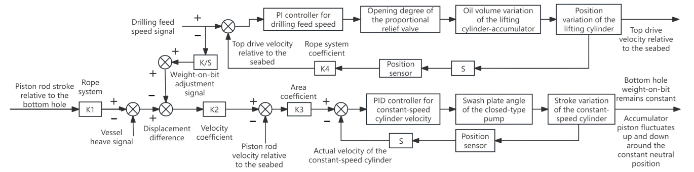
However, the lifting compensation system achieves automatic drilling feed by adjusting the overflow valve of the C oil circuit between the cylinder and the accumulator. If the oil volume in the C oil circuit decreases, for drill string compensation, the accumulator piston will move upward under the action of the gas cylinder while maintaining the bottom-hole drilling pressure unchanged. In this case, the purpose of automatic drilling feed cannot be achieved. Therefore, during automatic drilling feed, it is necessary to integrate the drilling feed speed to obtain lowering displacement, then sum this lowering displacement. This displacement is combined with the drilling pressure control signal, and automatic drilling feed is controlled by using two sets of nested PID closed-loop operations. Meanwhile, the accumulator piston fluctuates around the mid-position. Based on this idea, the established control logic is shown in Figure 7.
As illustrated in Figure 7, the control architecture comprises two main sections. The lower section governs the semi-active compensation, while the upper section handles the automatic drilling feed. These two sections are interconnected via the integral of the drilling feed signal, which functions as a position compensation command. This signal is combined with the drilling pressure adjustment signal and then input into the control system. This configuration enables the constant-speed cylinder to actively regulate the accumulator piston position while simultaneously facilitating automatic drilling feed.
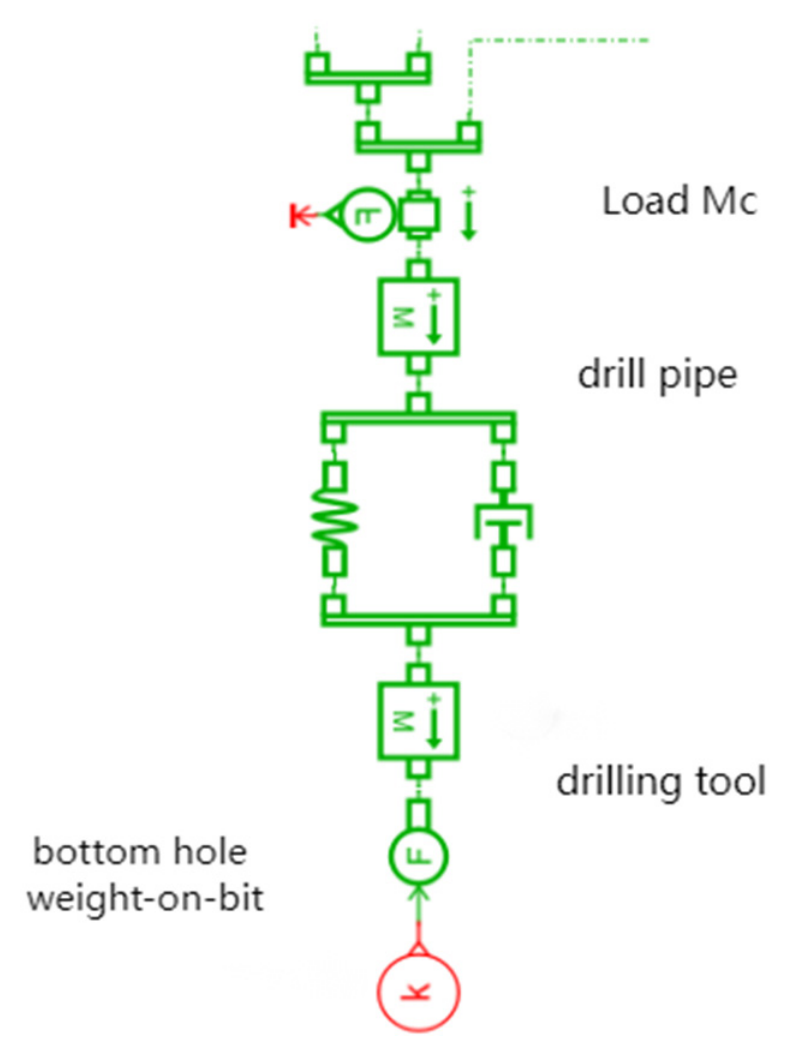
Regarding the establishment of the drill string model, reference can be made to the conventional drill string compensation model. However, a key distinction lies in the boundary condition: the conventional model typically assumes a fixed wellhead, i.e., the wellhead is treated as a stationary reference point relative to the ground. In the context of automatic drilling feed, if the wellhead were similarly fixed during simulation, downward movement of the drill string would be precluded. To address this, a constant force of 250 kN is applied to the drilling tool in place of the variable drilling pressure. The resulting drill string–bottom-hole model is depicted in Figure 8.
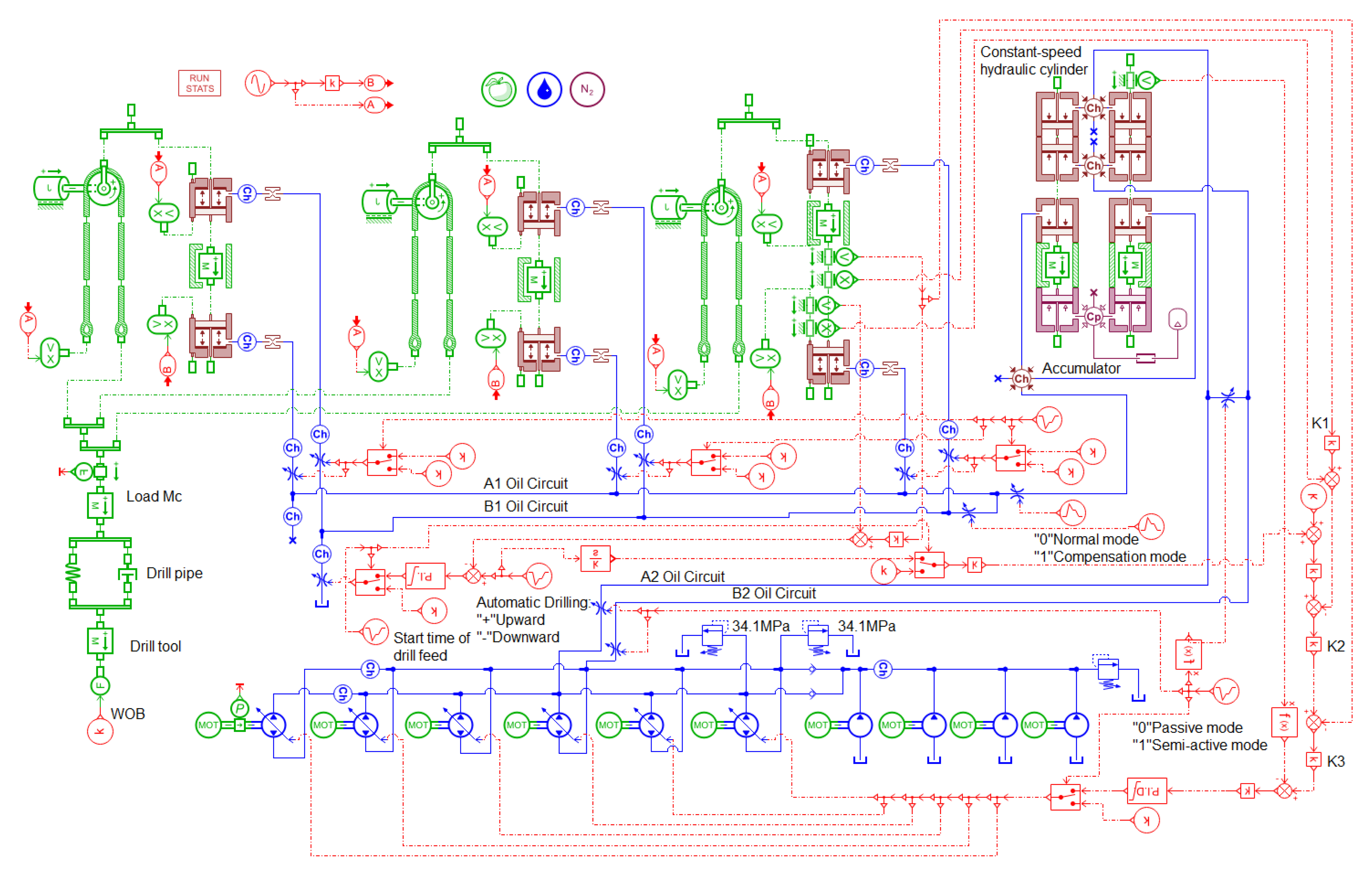
In Figure 8, the concentrated mass MC of the drill string, as well as its friction and damping values, are all derived from the drill string compensation conditions, which are directly related to the drilling depth. The mass of the drilling tool under applied drilling pressure is 1 t, and its friction is neglected. Since the pressure control of the proportional relief valve is quite difficult, a throttle valve is used instead of the proportional relief valve—their working principles are similar, but the control difficulty is reduced. This simplified treatment method is feasible for verification of the proposed principle. By combined this with the previous control process, the simulation model of automatic drilling is established, as shown in Figure 9.
The nested PID control strategy is adopted in this study primarily because the system requires simultaneous control of two variables: weight-on-bit (WOB) and drilling feed speed. By integrating the actual feed speed, the lowering displacement is obtained, and this displacement signal is introduced into the inner loop of the WOB control PID for computation. This ensures that both WOB and feed speed remain closed-loop controllable, and the nested PID structure is the key to achieving this dual-variable coordinated control. The key parameters of the automatic drilling feed simulation model are listed in Table 2. The PID parameters presented in the table are obtained through a simulation-aided iterative tuning approach based on the Ziegler–Nichols critical gain method—the inner compensation loop is tuned first and the outer drilling feed loop second, with settling time ≤ 10 s, velocity overshoot ≤ 5% and steady-state error ≤ 1% as convergence criteria—rather than trial-and-error or purely empirical methods, thereby ensuring the stability and adaptability of the controller under various operating conditions. However, considering the limitations of traditional empirical tuning, introducing advanced metaheuristic algorithms (such as improved particle swarm optimization) to dynamically optimize control parameters represents a promising direction for achieving faster convergence and higher precision in complex dynamic tracking [44].
Based on the mathematical framework from Section 2.1, five scenarios with distinct vertical well trajectories are analyzed. By omitting non-vertical string segments, the dynamic characteristics of the longitudinal vibration model—under a constant WOB (weight-on-bit) of 250 kN—as shown in Table 3:
Table 3. Key parameters of drill string model under different drilling depths.
Vertical Drilling Depth L (m)Drilling String Weight M drill (t)Concentrated Mass M C (t)Mud Damping C 2 (kN·s/m)Drilling String Stiffness K 2
12,500459.6643.224.6863.7
14,000515716.827.6557.5
15,000551.8765.829.6253.95
16,000588.6814.631.6050.83
17,000625.486333.5748.0

4. Simulation of Automatic Drilling Feed Performance Under Operating Conditions

This part explores the performance of the automatic drilling function of the lifting system. In offshore drilling operations, the drill string compensation function should also be started during automatic drilling. Firstly, the effect of activating semi-active compensation on automatic drilling is discussed. Then, the influence of two conditions in the process of automatic drilling (semi-active compensation of activation and deactivation) on the bottom-hole drilling pressure is analyzed. Finally, the influence of sea conditions on automatic drilling is studied.

4.1. Simulation Analysis of Automatic Drilling Feed When Compensation Is Activated

Consistent with the parameter setting in Section 3.1, the hull heave motion parameters under different sea state grades are derived from reference [34] and are adopted as the simulation excitation conditions, as listed in Table 4:
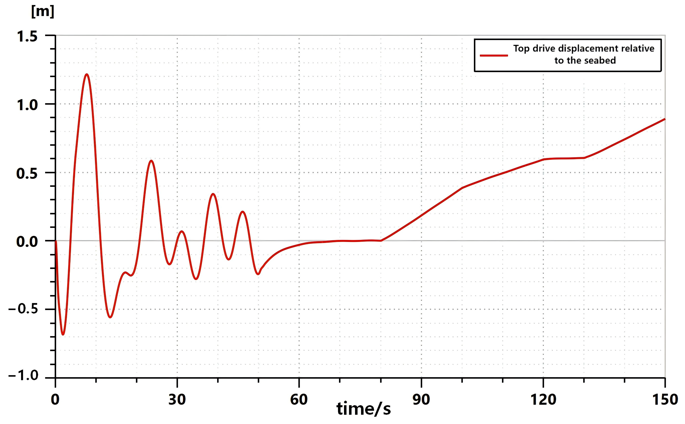
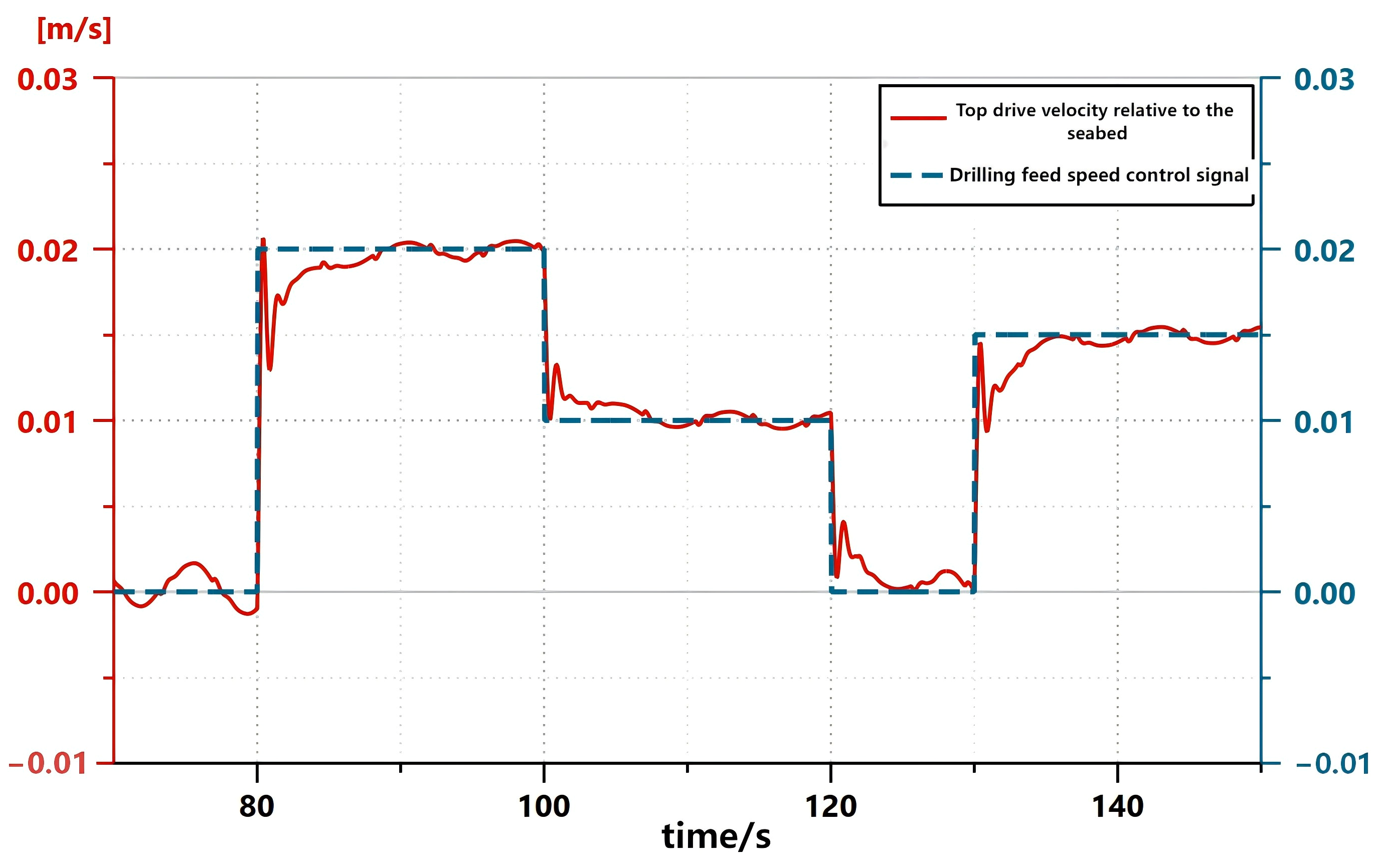
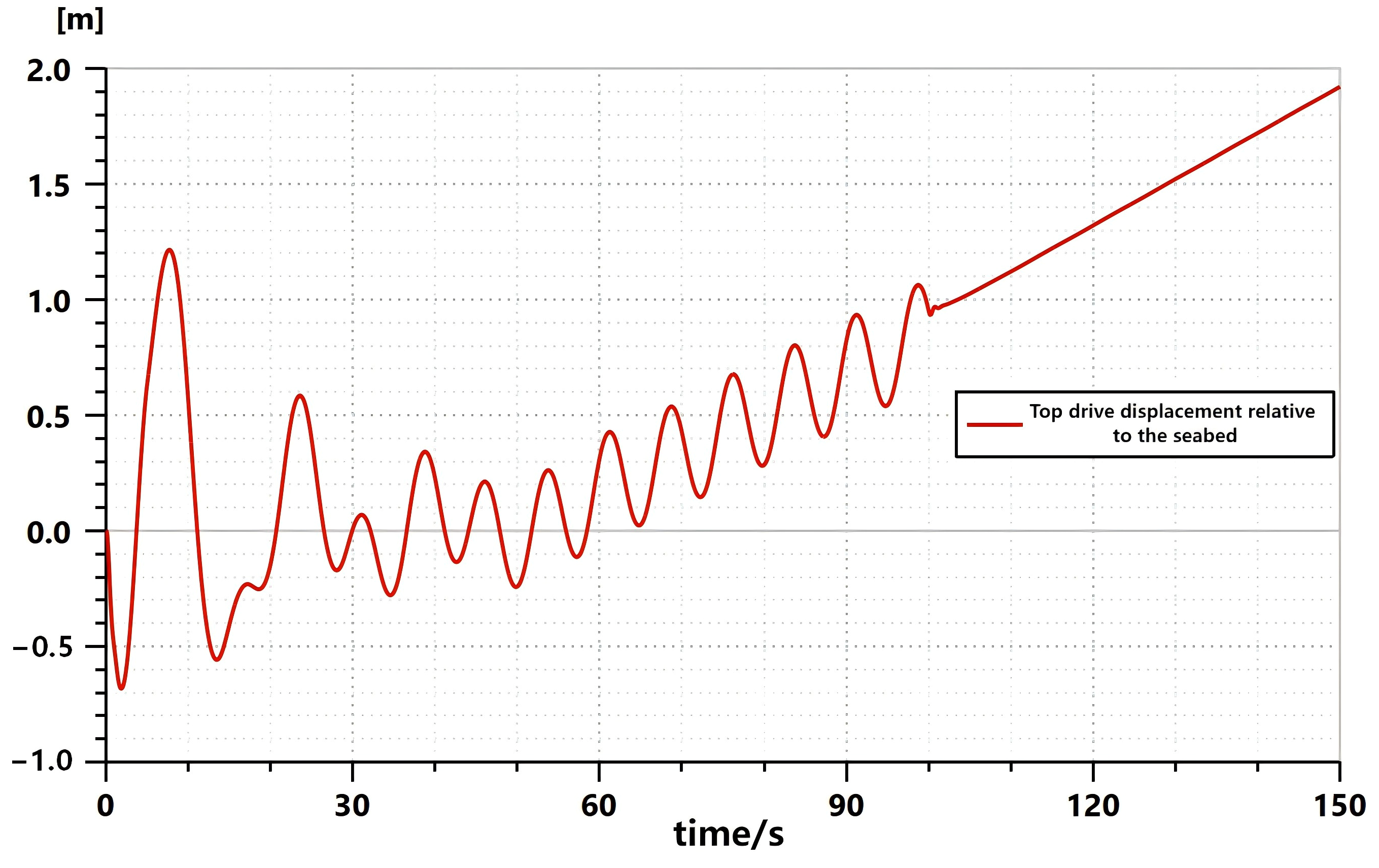
The simulation was conducted under Grade 4 sea conditions, with a drill string length of 12,500 m, a simulation duration of 150 s, and a sampling period of 0.05 s. The system was set to be in a hard-connected state from 0 s to 5 s, i.e., the cylinder drove the drill string and the lifting cylinder did not enter the plunger cylinder mode. From 5 s to 50 s, the cylinder entered the plunger cylinder mode, and passive compensation was activated. From 50 s to 80 s, the semi-active compensation function was turned on, and the drill string compensation switched to the semi-active compensation mode. From 80 s to 100 s, the automatic drilling feed speed signal was set to 0.02 (0.02 represents a lowering speed of 0.02 m/s; “+” indicates lowering, while “−“ indicates lifting). From 100 s to 120 s, the drilling feed speed signal was 0.01. From 120 s to 130 s, the drilling feed signal was 0. From 130 s to 150 s, the drilling feed signal was −0.02. The simulated displacement and velocity of the top drive relative to the seabed are shown in Figure 10 and Figure 11, respectively.
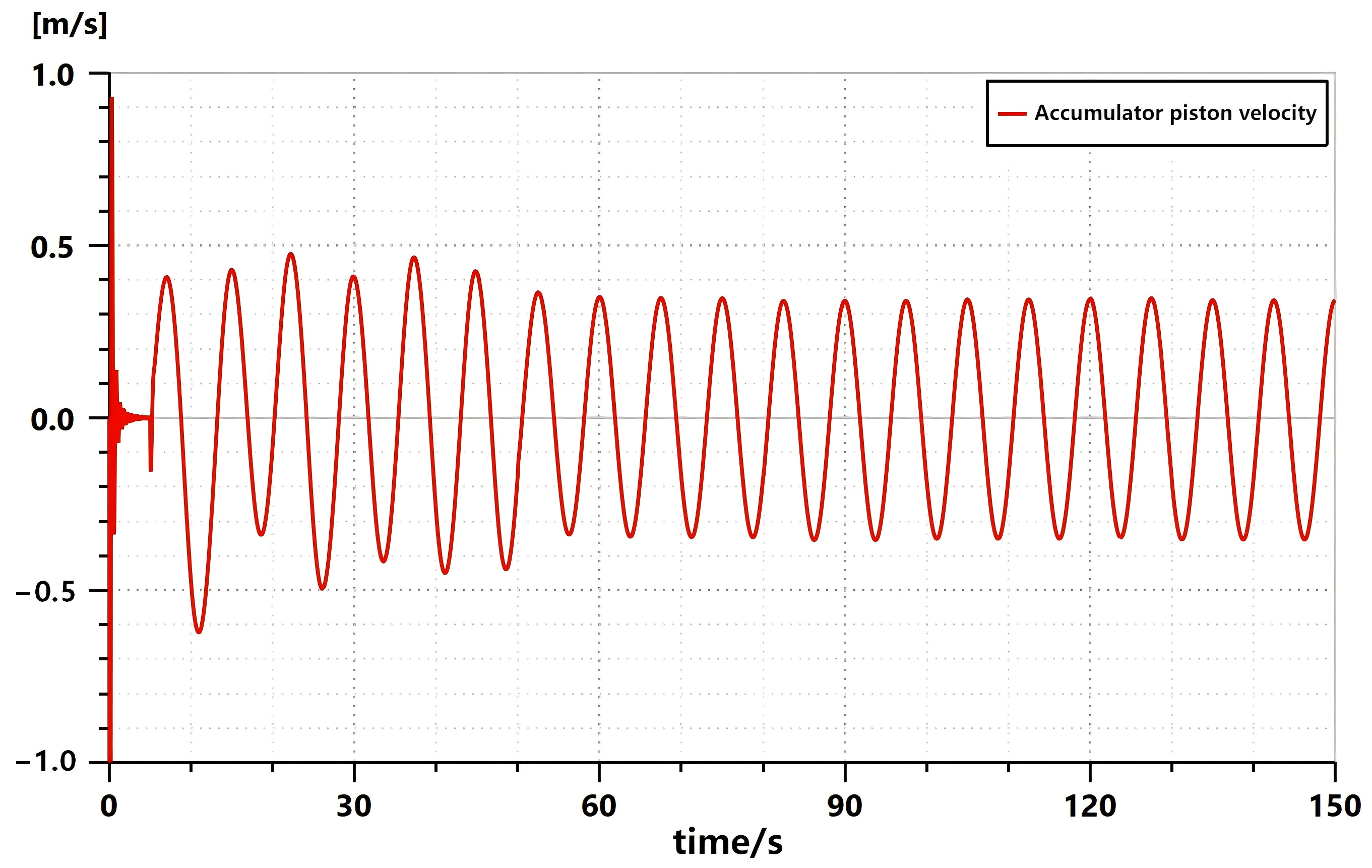
According to the observations in Figure 10, the top drive displacement undergoes an abrupt change from 0 s to 5 s, which is caused by the severe collision between the bottom of the drill string and the well bottom due to heave motion when the drill string is in a hard-connected state. From 5 s to 50 s, the passive drill string compensation function is activated, and the amplitude of the top drive displacement variation decreases, but the bottom-hole drilling pressure still fluctuates drastically during this period. It can also be seen that after the drilling feed command changes, the system adjustment time is approximately 10 s, which is caused by hydraulic pressure build-up, load inertia, friction, and other factors. This phenomenon is close to actual engineering conditions. In the interval from 50 s to 80 s, after the semi-active compensation function is turned on, the top drive displacement approaches 0 m, and the bottom-hole drilling pressure remains constant at this moment. Combined with Figure 11 after 80 s, the automatic drilling feed is activated, and the top drive descends slowly. The descending speed reaches 0.02 m/s 10 s later (at 90 s) and then fluctuates around this value. After 100 s, since the joystick signal changes from 0.02 to 0.01, the lowering speed of the top drive also undergoes an abrupt change, and it takes approximately 10 s for the speed to decrease to the set value. Similarly, after 120 s, the joystick returns to 0, and the top drive position remains constant for 10 s. After 130 s, with the drilling feed signal given again, the top drive starts descending once more. By observing the velocity curve, it can be seen that each time the drilling feed velocity signal is given, the system takes about 10 s to adjust the top drive velocity to the set value, and this adjustment time is determined by the system itself. The extracted accumulator piston velocity curve is shown in the Figure 12.
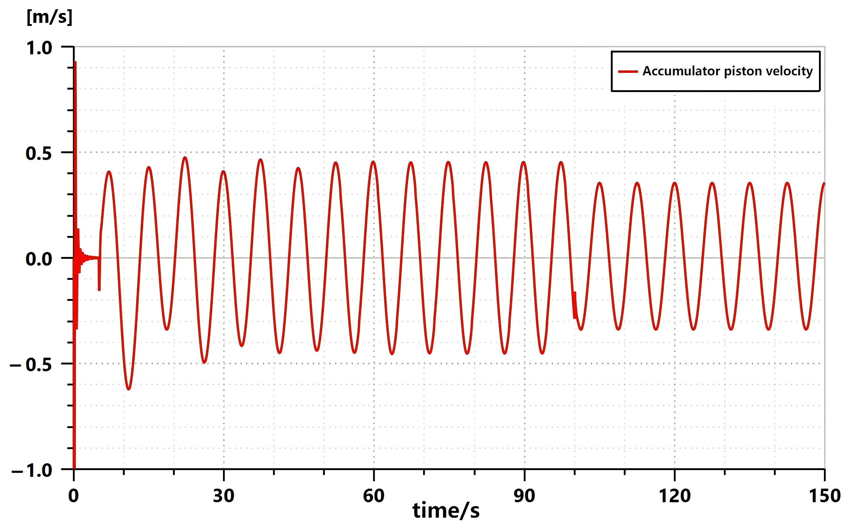
By observing the accumulator piston velocity curve, it can be seen that throughout the processes of passive compensation, semi-active compensation and automatic drilling feed, the accumulator piston fluctuates up and down near the neutral position. It is thus evident that the entire set of control algorithms for automatic drilling feed does not exert an impact on the accumulator piston displacement, and there is no risk of cylinder collision for the piston. It can be concluded that the automatic drilling feed method using drill string compensation combined with a proportional relief valve is feasible in principle, and the control logic designed for this type is also applicable.

4.2. Comparison of Automatic Drilling Feed Performance When Semi-Active Compensation Is Activated and Deactivated

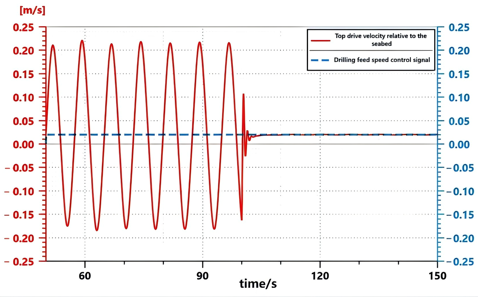
Under the same conditions of Grade 4 sea conditions and a drilling depth of 12,500 m, the simulation was carried out with a duration of 150 s and a sampling period of 0.05 s. The system was set to be in a hard-connected state from 0 s to 5 s. From 5 s to 100 s, the cylinder entered the plunger cylinder mode and passive compensation was activated. Meanwhile, the automatic drilling feed function was turned on at 50 s, and the drilling feed signal was set to 0.02 throughout the period from 50 s to 150 s. After 100 s, semi-active compensation was activated. The performance of automatic drilling feed in the passive compensation mode (50–100 s) and in semi-active compensation mode (100–150 s) was compared.
The displacement curve from 0 s to 50 s is consistent with that in Figure 13. After 50 s, passive compensation is activated and the automatic drilling feed signal is set to 0.02 at the same time, so the top drive fluctuates and moves downward along a curve with a slope of 0.02. After 100 s, the top drive continues to move downward and no longer fluctuates at this time. The reason for this phenomenon is that the activation of semi-active compensation after 100 s greatly reduces the fluctuation of the top drive. It can also be seen from Figure 14 that with the activation of semi-active compensation, the velocity of the top drive relative to the seabed transitions from a fluctuating state to an almost constant state, and the efficiency of automatic drilling feed is markedly enhanced. A short transient adjustment process exists during the compensation mode switch: although the mode switching action itself is relatively fast, the subsequent hydraulic pressure build-up and closed-loop control regulation require a certain transition time as an inherent characteristic of the electro-hydraulic system. Furthermore, the accumulator demonstrates stable operation without cylinder collision, as illustrated in Figure 15.

4.3. Influence of Sea Conditions on Automatic Drilling Feed Capability

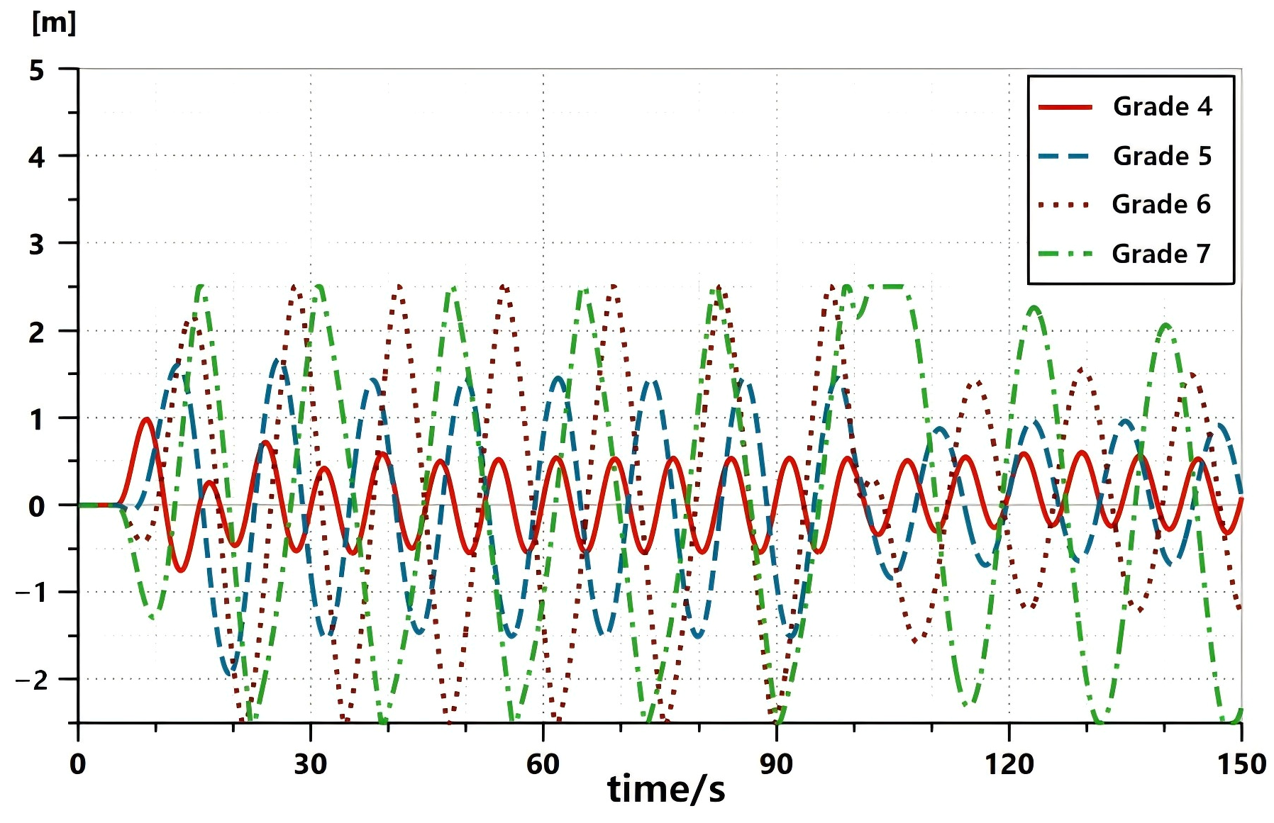
The influence of sea conditions on automatic drilling feed lies mainly in drill string compensation, and the performance of drill string compensation directly determines the capability of automatic drilling feed. In this section, a simulation study is conducted on the drilling feed process under different sea conditions. Four sea conditions (Grades 4, 5, 6, and 7) are selected, with a simulation duration of 150 s and a drilling depth of 12,500 m. The system is set to be in a hard-connected state from 0 s to 5 s. From 5 s to 100 s, the cylinder enters the plunger cylinder mode, and passive compensation is activated. Meanwhile, the automatic drilling feed function is turned on at 50 s, and the drilling feed signal is set to 0.02 throughout the period from 50 s to 150 s. After 100 s, semi-active compensation is activated. The performance of automatic drilling feed under different sea conditions is compared after passive compensation and semi-active compensation are activated.
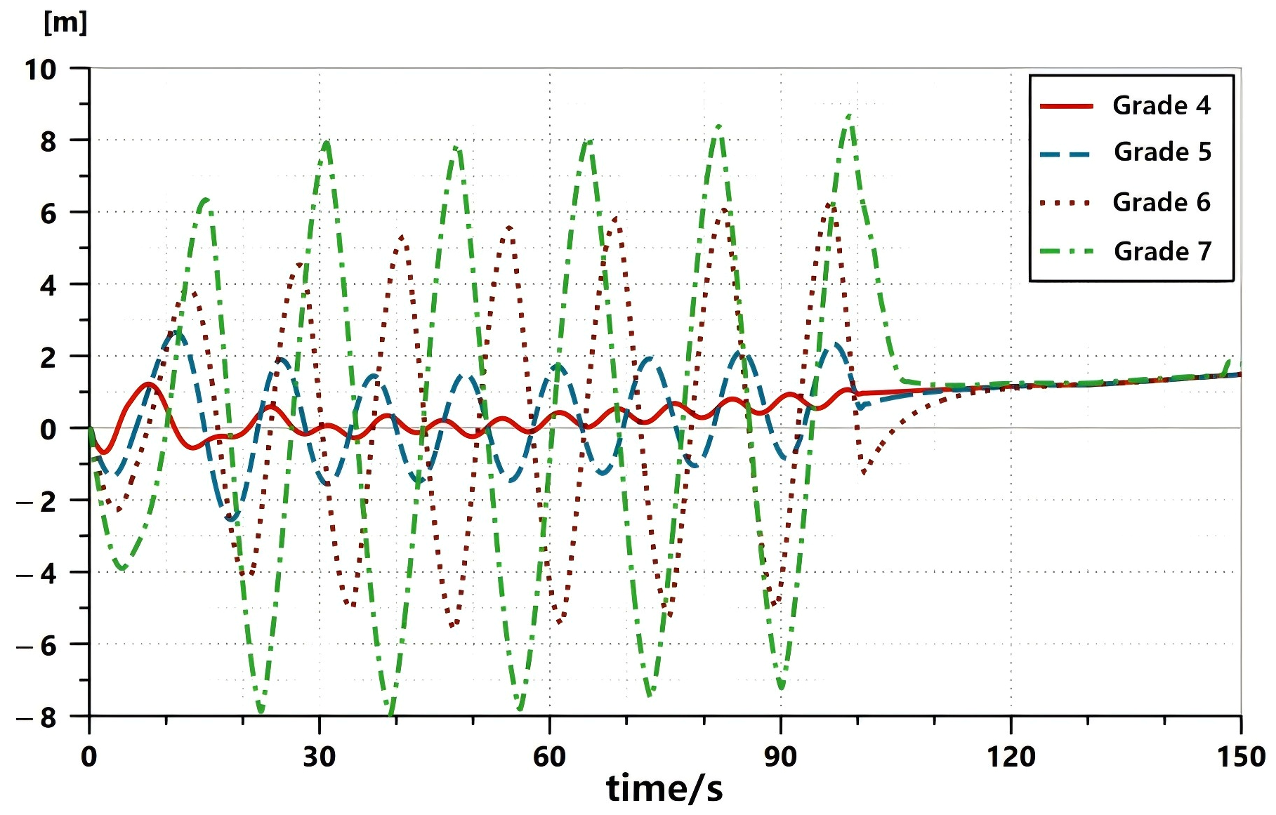
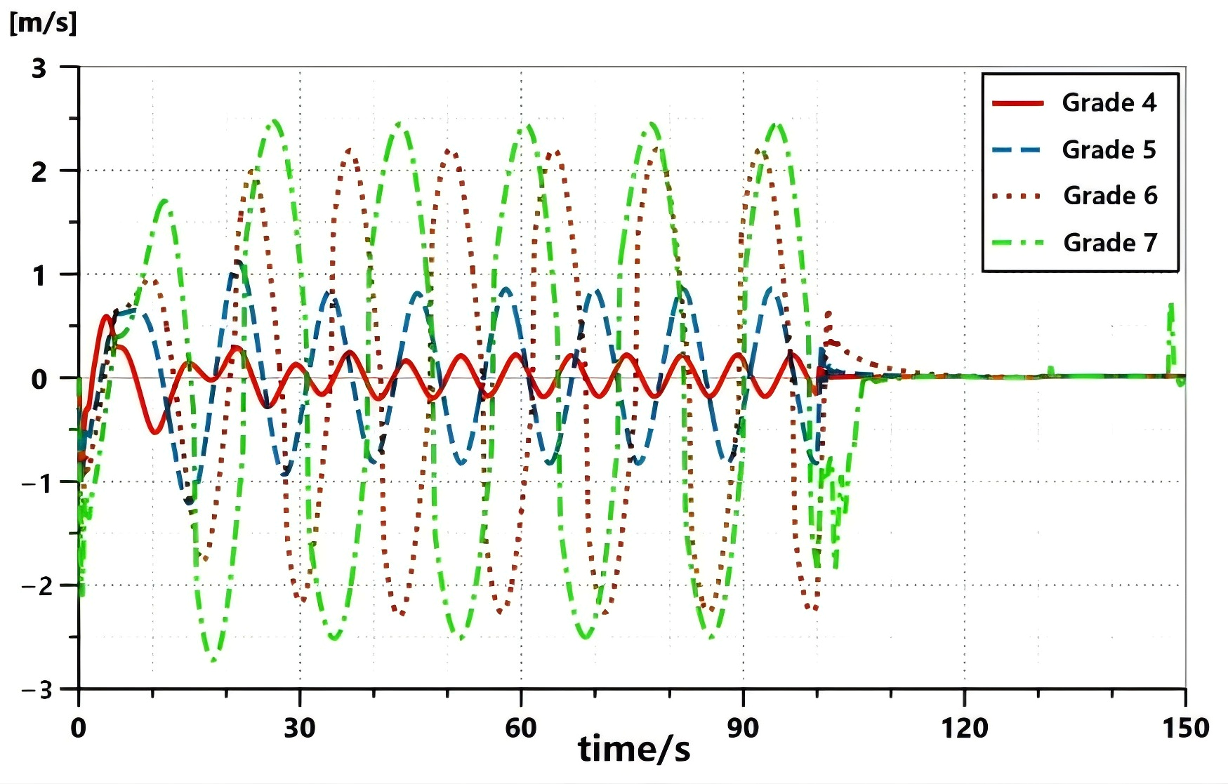
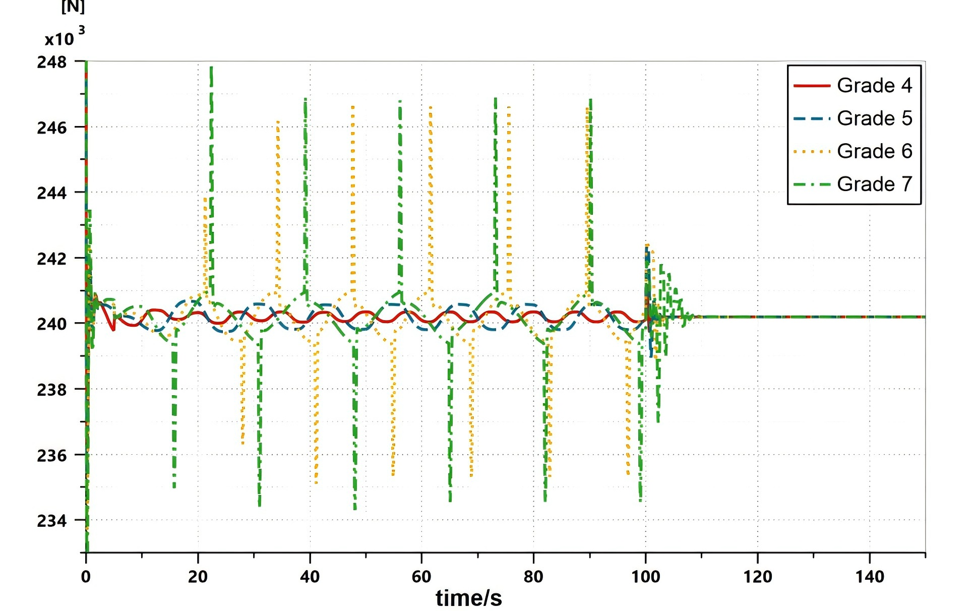
By observing the accumulator piston displacement curve in Figure 16, it can be seen that when the sea condition reaches Grade 6, during the period from 5 s to 100 s, the accumulator piston reaches the limit position of 2.5 m, and the passive compensation system faces a risk of cylinder impact. It can be seen from Figure 17 and Figure 18 that both the top drive displacement and its movement velocity can well follow the automatic drilling feed commands. Whether passive compensation or semi-active compensation is activated, the top drive displacement moves downward along a curve with a constant slope under different sea conditions. Observing Figure 19, it can be seen that after the passive compensation is activated, the WOB fluctuations under sea Grade 4 and 5 can be maintained around 240 kN, with more severe sea states leading to greater WOB fluctuations. However, under sea Grade 6 or above, due to the occurrence of accumulator cylinder impact incidents, the WOB exhibits peaks at specific time points. When the semi-active compensation is activated, the WOB can be well maintained in all cases. In summary, to reduce the occurrence of accidents during automatic drilling feed, the semi-active compensation function should be activated as soon as possible during drilling feed operations. The maximum applicable sea condition for this function is Grade 6, and operations are not recommended when the sea condition exceeds this level. It should be noted that this Grade 6 limit is not an inherent property of the control scheme, but rather depends on the hardware parameters of the accumulator, specifically the piston stroke of 0.74 m and the effective volume of 1144.5 L (as listed in Table 2). If a different accumulator with a larger stroke or greater volume were used, the system would be capable of tolerating higher sea conditions (e.g., Grade 7 or above). Conversely, a smaller accumulator would lower the maximum applicable sea condition. Therefore, the operability limit presented herein is strictly associated with the specific accumulator configuration adopted in this study. For practical engineering applications, the accumulator specifications should be selected according to the target sea state requirements.
Figure 16. Comparison of accumulator piston displacement under different sea conditions.
Jmse 14 01184 g016
Figure 17. Comparison of top drive displacement relative to the seabed under different sea conditions.
Jmse 14 01184 g017
Figure 18. Comparison of top drive velocity relative to the seabed under different sea conditions.
Jmse 14 01184 g018
Figure 19. Comparison of WOB fluctuation curves under different sea conditions.
Jmse 14 01184 g019

5. Conclusions

(1)
Modeling achievements: To address the control coupling challenge between automatic drilling feed and drill string compensation in offshore drilling, a longitudinal vibration model of the drill string was established based on lumped mass, stiffness, damping principles, and the Rayleigh method. A simulation model incorporating bottom-hole mechanics and nested PID closed-loop control was built on the AMESim platform. Model parameters were calibrated against relevant industry standards, meeting engineering analysis requirements.
(2)
Control performance: The proposed integrated control architecture combining closed-loop relief valve pressure regulation with drill string compensation demonstrates good feasibility and superiority. By integrating the drilling feed velocity to generate a position compensation signal and coupling it with the WOB control input, coordinated operation between compensation and drilling feed is achieved. After semi-active compensation activation, the top drive velocity response time is approximately 10 s, enabling accurate tracking of set feed rates (0.01–0.02 m/s), while the accumulator piston oscillates stably around the neutral position without cylinder collision risk.
(3)
Sea state operability limit: Under representative drilling conditions (12,500 m vertical depth, 250 kN set WOB), the maximum applicable sea condition for the integrated system is Grade 6 (heave wave height 4.578 m, period 14 s). Beyond this threshold, the passive compensation mode faces accumulator piston collision risk, whereas semi-active compensation extends the effective operating envelope, maintaining stable drilling feed under Grade 5–6 conditions (Grade 7 operations are inadvisable without modification). It should be noted that this operability limit strictly applies to the specific well depth, accumulator stroke, hydraulic parameters, and set WOB used in this study. For different parameter configurations, re-evaluation based on the proposed method is required.
(4)
Engineering value: The integrated design, which combines hoisting and drill string compensation functions with closed-circuit hydraulic architecture and an energy storage inverter unit, simplifies the drilling package structure, enables recovery of lowering potential energy, and eliminates control coupling interference. This technology provides an accurate and stable solution for high-end offshore applications such as ultra-deepwater drilling, natural gas hydrate exploitation, and precision ocean drilling and coring.
(5)
Future research: subsequent work will focus on prototype experimental validation, energy recovery efficiency investigation, adaptive control algorithm development for real-time sea state-based mode switching, and modeling extension to horizontal section drilling dynamics for directional and extended-reach drilling.
It should be noted that this study has certain limitations. Due to the lack of prototype testing, field measurement data, and benchmark experimental results, direct comparative validation against physical experiments or existing systems is not provided. Furthermore, a rigorous stability analysis of the nested PID controller under periodic wave disturbances—such as gain margin and phase margin assessment based on a linearized model—was not performed. The above simulation findings need to be further supplemented and confirmed through subsequent hardware-in-the-loop or real-machine tests, as well as future frequency-domain stability verification.

Author Contributions

Conceptualization, J.L. and C.L.; methodology, J.L. and C.L.; software, J.L., H.L., and R.S.; validation, J.L., H.L., R.S., and L.W.; formal analysis, J.L. and L.W.; investigation, Q.W.; resources, H.L. and R.S.; data curation, Q.W.; writing—original draft preparation, J.L.; writing—review and editing, C.L. and L.W.; visualization, Q.W.; supervision, C.L.; project administration, C.L.; funding acquisition, C.L. All authors have read and agreed to the published version of the manuscript.

Funding

This research was funded by the Sichuan Provincial Natural Science Foundation of China (Grant No. 2025NSFSC2096); the General Program of Sichuan Provincial Department of Science and Technology (Grant No. 2026NSFSC0093); the National Natural Science Foundation of China (Grant No. 52501340); the Shandong Provincial Natural Science Foundation of China (Grant No. ZR2025QC558); and the Qingdao Youth Science and Technology Program of Natural Science Foundation (Grant No. 25-1-1-70-zyyd-jch);and the School-level Project of Chengdu Technological University (Grant No. 2024ZR010).

Data Availability Statement

Access to the underlying data supporting the findings of this research may be obtained from the corresponding author upon justified inquiry.

Conflicts of Interest

Authors Huan Li and Rui Su were employed by the CNPC Baoji Oilfield Machinery Company Limited. The remaining authors declare that the research was conducted in the absence of any commercial or financial relationships that could be construed as a potential conflict of interest.

References

  1. Yang, J.; Li, L.; Song, Y.; Gang, T.; Minghe, Z.; Hui, Z. Current status and prospects of offshore oil and gas drilling technology development in China. Acta Pet. Sin. 2023, 44, 2308. [Google Scholar]
  2. Wang, H.; Huang, H.; Bi, W.; Ji, G.; Zhou, B.; Zhuo, L. Deep and ultra-deep oil and gas well drilling technologies: Progress and prospect. Nat. Gas. Ind. B 2022, 9, 141–157. [Google Scholar] [CrossRef]
  3. Zhang, G.; Ma, F.; Liang, Y.; Zhao, Z.; Qin, Y.; Liu, X.; Zhang, K.; Ke, W. Global deep oil and gas exploration fields and theoretical technology progress. Acta Pet. Sin. 2015, 36, 1156–1166. [Google Scholar]
  4. Wu, G.; Fang, H.; Han, Z.; Hu, X. Characteristics of China’s oil and gas reserve growth during the “12th Five-Year Plan” period and prospect for the “13th Five-Year Plan”. Acta Pet. Sin. 2016, 37, 1145–1151. [Google Scholar]
  5. Wang, D.; Ding, L. Current status and development trend of offshore drilling platform technology. Pet. Mach. 2010, 38, 69–72. [Google Scholar]
  6. Niedzwecki, J.M.; Thampi, S.K. Heave compensated response of long multi-segment drill strings. Appl. Ocean Res. 1988, 10, 181–190. [Google Scholar] [CrossRef]
  7. Ren, K.; Shen, D.; Wang, D.; Xiao, R.; Li, P.; Nan, S. Technical analysis of offshore drilling heave compensation system. Pet. Mach. 2009, 37, 125–128. [Google Scholar]
  8. Lu, C.; Gan, C.; Chen, L.; Chen, X.; Cao, W.; Wu, M. Development and prospect of intelligent control of geological drilling process. Coal Geol. Explor. 2023, 51, 16. [Google Scholar]
  9. Guan, Z.; Chen, T.; Liao, H. Theory and Technology of Drilling Engineering; Springer: Singapore, 2021. [Google Scholar]
  10. Jalayeri, E.; Imam, A.; Tomas, Z.; Sepehri, N. A throttle-less single-rod hydraulic cylinder positioning system: Design and experimental evaluation. Adv. Mech. Eng. 2015, 7, 1687814015583249. [Google Scholar] [CrossRef]
  11. Rudshaug, B.; Skibelid, T. Modern Use of Closed-Loop Hydraulics for Controlling and Powering of Cylinder-Based Hoisting Systems. In Proceedings of the SPE/IADC Drilling Conference, Amsterdam, The Netherlands, 9–11 March 1999. [Google Scholar]
  12. Greenfield, W.D.; Lubinski, A. Use of Bumper Subs When Drilling From Floating Vessels. In Proceedings of the American Institute of Mining, Metallurgical, and Petroleum Engineers, Dallas, TX, USA, 2–5 October 1967. [Google Scholar]
  13. Jan, A. A New Concept Drilling Hoisting Systems Rigs. Acta Montan. Slovaca 2006, 11, 1–9. [Google Scholar]
  14. Zhang, Y.; Huang, L.; Liu, M.; Zhang, L. Semi-active drilling drawworks heave compensation system. Pet. Explor. Dev. 2013, 40, 620–624. [Google Scholar] [CrossRef]
  15. Zhang, Y.; Huang, L.; Meng, D.; Liu, Z.; Liang, H.; Xu, Y.; Ren, K.; Nan, S.; Feng, Y. Energy consumption calculation and experimental test of offshore rig compensation winch. Acta Pet. Sin. 2015, 36, 620–625. [Google Scholar] [CrossRef]
  16. Huang, L.; Zhang, Y.; Liu, M.; Qi, M. Design of heave compensation system for offshore floating drilling platform winch. Acta Pet. Sin. 2013, 34, 569–573. [Google Scholar]
  17. Aarsnes, U.J.F.; Aamo, O.M. Linear stability analysis of self-excited vibrations in drilling using an infinite dimensional model. J. Sound Vib. 2016, 360, 239–259. [Google Scholar] [CrossRef]
  18. ISO 11961; Petroleum and Natural Gas Industries-Steel Drill Pipe. ISO Copyright Office: Geneva, Switzerland, 2018.
  19. Zhou, W. Simulation of hydraulic system faults for marine machinery based on AMESim. J. Coast. Res. 2019, 94, 357–361. [Google Scholar] [CrossRef]
  20. Zhao, P.; Chen, Y.; Zhou, H. Review of hybrid hydraulic construction machinery systems and control strategies. J. Zhejiang Univ. (Eng. Sci.) 2016, 50, 449–459. [Google Scholar]
  21. Li, H.; Li, P.; Li, L.; Fan, S.; Zheng, W. AMESim based simulation study of closed cylinder lifting system. China Pet. Mach. 2021, 49, 59–66. [Google Scholar]
  22. Li, H.; Li, P.; Zheng, W.; Liu, Q.; Bai, L. Research on key technologies of closed hydraulic cylinder lifting system for offshore applications. Oil Field Equip. 2021, 50, 18–25. [Google Scholar]
  23. Per, V. Apparatus and Method for Raising and Lowering A Piston Cylinder Arrangement in A Derrick. U.S. Patent 6,094,910, 8 January 2000. [Google Scholar]
  24. Zhang, W.; Yuan, Q.; Xu, Y.; Wang, X.; Bai, S.; Zhao, L.; Hua, Y.; Ma, X. Research on control strategy of electro-hydraulic lifting system based on AMESim and MATLAB. Symmetry 2023, 15, 435. [Google Scholar] [CrossRef]
  25. Yao, J.; Wang, P.; Dong, Z.; Jiang, D. A novel position control with online parameter estimation for electro-hydraulic servo systems. IEEE/ASME Trans. Mechatron. 2020, 26, 1054–1065. [Google Scholar]
  26. Zhang, Y.; Zhu, D.; Chen, M.; Yang, S.X. Model predictive tracking control based on adaptive sliding mode constraints for unmanned underwater vehicles. Intell. Robot. 2026, 6, 101–119. [Google Scholar] [CrossRef]
  27. Hatleskog, J.T.; Dunnigan, M.W. Heave compensation simulation for non-contact operations in deep water. Ocean Eng. 2007, 34, 544–552. [Google Scholar]
  28. Godhavn, J.M. Control requirements for automatic managed pressure drilling in harsh environments. SPE Drill. Complet. 2010, 25, 174–183. [Google Scholar] [CrossRef]
  29. Gong, J.; Zhang, D.; Guo, Y.; Tang, Z.; Liu, C.; Hu, P.; Zhao, Y.; Quan, W.; Jin, Y. Potential energy recovery method based on alternate recovery and utilization of multiple hydraulic cylinders. Autom. Constr. 2020, 112, 103105. [Google Scholar] [CrossRef]
  30. Qiao, S.; Hao, Y.; Quan, L.; Ge, L.; Xia, L. A novel electro-hydraulic compound driving system with potential energy regeneration capability for lifting device. IEEE Access 2022, 10, 18248–18256. [Google Scholar] [CrossRef]
  31. Triet, H.H.; Ahn, K.K. Comparison and assessment of a novel energy recovery system for hydraulic excavators. Int. J. Precis. Eng. Manuf.-Green Tech. 2021, 8, 1111–1129. [Google Scholar]
  32. Zheng, W.; Yang, H.; Mou, X.; Li, D.; Li, L. Development and application of 60t drill string heave compensation device. China Pet. Mach. 2020, 48, 58–63. [Google Scholar]
  33. DNV-RP-H103; Modelling and Analysis of Marine Operations. Det Norske Veritas: Oslo, Norway, 2011.
  34. Ju, S.; Chang, Y.; Chen, G.; Liu, X.; Xu, L.; Wang, R. Operation window analysis of deepwater drilling riser connection. Pet. Explor. Dev. 2012, 39, 105–110. [Google Scholar] [CrossRef]
  35. Wang, W.; Zhou, T.; Yu, X.; Zhang, P. Heave motion analysis of floating drilling platform. Pet. Mine Mach. 2011, 40, 36–38. [Google Scholar]
  36. Liu, Q.; Xu, T. Current status and development of deep-sea drilling heave compensation devices in China. J. Southwest Pet. Univ. (Sci. Technol. Ed.) 2014, 36, 1–8. [Google Scholar]
  37. Meena, K.; Dhavalikar, M.; Thorat, S. A review on the position control of hydraulic cylinder for accuracy and response time. Mater. Today Proc. 2023, 72, 995–999. [Google Scholar] [CrossRef]
  38. Zhang, M.; Hu, X.; Li, B. Compensation mechanism analysis of semi-active drill string heave compensation system. China Pet. Mach. 2012, 40, 57–60. [Google Scholar]
  39. Lin, T.; Ye, Y.; Fu, S.; Liu, Q. Energy-saving drive system for hydraulic excavator swing based on electric energy recovery. China J. Highw. Transp. 2014, 27, 120–126. [Google Scholar]
  40. Liu, C.; Wu, L.; Li, G.; Zhang, H.; Xiao, W.; Xu, D.; Guo, J.; Li, W. Improved multi-search strategy A* algorithm to solve three-dimensional pipe routing design. Expert Syst. Appl. 2024, 240, 122313. [Google Scholar] [CrossRef]
  41. Liu, C.; Wu, L.; Li, G.; Zhang, H.; Xiao, W. AI-based 3D pipe automation layout with enhanced ant colony optimization algorithm. Autom. Constr. 2024, 167, 105689. [Google Scholar] [CrossRef]
  42. Wang, W.; Hu, N.; Yang, X.; Wang, T.; Gao, P. Configuration and layout study of pipe handling system for ultra-deepwater drilling rig. Ship 2017, 28, 87–91. [Google Scholar]
  43. Lei, J.; Wang, Q.; Li, H.; Su, R.; Wang, L.; Liu, C. A novel cylinder lifting system design and simulation with integrated drill pillar compensation function. Appl. Ocean Res. 2025, 164, 104629. [Google Scholar] [CrossRef]
  44. Liu, H.; Jiang, Y.; Liu, M.; Yang, F.; Zhang, H. Path planning with obstacle avoidance for soft robots based on improved particle swarm optimization algorithm. Intell. Robot. 2023, 3, 565–580. [Google Scholar] [CrossRef]
Figure 1. Schematic diagram of RamRig dual-wellhead deck layout.
Jmse 14 01184 g001
Figure 3. Structural principle of the cylinder hoisting system. 1—hoisting cylinder, 2—hydraulic station, 3—compensation accumulator, 4—oil circuit switching valve group, 5—cylinder valve group, 6—accumulator valve group, 7—safety valve group, 8—main gas valve group, 9—pressure increasing/decreasing control valve group, 10—high-pressure gas cylinder group, 11—energy storage inverter unit.
Jmse 14 01184 g003
Figure 4. Circuit configurations of the passive and semi-active drill string compensation. (a) Passive compensation. (b) Semi-active compensation.Arrows beside the hydraulic cylinder denote the direction of cylinder motion; arrows beside the pipelines denote the flow direction of the working medium.
Jmse 14 01184 g004
Figure 5. Schematic diagram of automatic drilling circuits under passive and semi-active compensation modes. (a) Passive compensation automatic drilling feed. (b) Semi-active compensation automatic drilling feed. Arrows beside the hydraulic cylinder denote the direction of cylinder motion; arrows beside the pipelines denote the flow direction of the working medium.
Jmse 14 01184 g005
Figure 6. Structural schematic diagram of the cylinder hoisting system. 1—Cylinder barrel, 2—cylinder piston rod, 3—top pulley block, 4—hoisting steel wire rope, 5—top drive, 6—drill string, 7—bottom-hole assembly.
Jmse 14 01184 g006
Figure 7. Joint control flow chart of automatic drilling feed and drill string compensation.
Jmse 14 01184 g007
Figure 8. Simulation model of automatic drilling feed drill string–bottom-hole system.
Jmse 14 01184 g008
Figure 9. Simulation model of automatic drilling feed.
Jmse 14 01184 g009
Figure 10. Variation of top drive displacement relative to seabed with time during automatic drilling feed.
Jmse 14 01184 g010
Figure 11. Variation curve of top drive velocity relative to seabed with time during automatic drilling feed.
Jmse 14 01184 g011
Figure 12. Variation curve of accumulator piston velocity with time during automatic drilling feed.
Jmse 14 01184 g012
Figure 13. Comparison of top drive displacement relative to the seabed.
Jmse 14 01184 g013
Figure 14. Comparison of top drive velocity relative to the seabed.
Jmse 14 01184 g014
Figure 15. Variation of accumulator piston velocity with time.
Jmse 14 01184 g015
Table 1. Hull heave parameters under different operating conditions.
Operating ConditionsHull Heave Wave Height (m)Hull Heave Period (s)Maximum Hull Heave Velocity (m/s)
Condition 11.3857.50.575
Condition 22.704120.71
Condition 34.578141.025
Condition 47.821171.445
Table 2. Key parameters of automatic drilling feed simulation model.
No.Parameter TypeCharacteristics
1Lifting CylinderPiston chamber diameter: 0.54 m; Rod chamber diameter: 0.46 m; Cylinder stroke: 18 m
2Compensation AccumulatorPiston chamber diameter: 0.54 m; Piston stroke: 0.74 m; Effective volume: 1144.5 L
3Nitrogen Cylinder BankVolume: 22,400 L
4Closed-type Pump UnitQuantity: 5 units; Displacement: 1 L/rev
Maximum system working pressure: 31.5 MPa
5Closed-loop Control Parameters for Drill String CompensationProportional gain P: 100; Integral gain I: 100; Derivative gain D: 1; Maximum output limit: −1~1; K1: 2; K2: 0.2; K3: −1.2; Drilling pressure signal: 0
6Closed-loop Control Parameters for Automatic Drilling FeedProportional gain P: 100; Integral gain I: 50; Maximum output limit: 0~1; Maximum drilling feed speed: 0.02 m/s (The maximum drilling speed in the reference is 60 m/h, so the value of 0.02 m/s is reasonable)
Table 4. Hull heave motion parameters under different sea conditions.
Sea Condition GradeHeave Wave Height (m)Heave Period (s)Maximum Motion Velocity (m/s)
Grade 41.3857.50.575
Grade 52.704120.71
Grade 64.578141.025
Grade 77.821171.445
Grade 812.623201.98
Disclaimer/Publisher’s Note: The statements, opinions and data contained in all publications are solely those of the individual author(s) and contributor(s) and not of MDPI and/or the editor(s). MDPI and/or the editor(s) disclaim responsibility for any injury to people or property resulting from any ideas, methods, instructions or products referred to in the content.