Article

A Novel Displacement Prediction Model for Inclined Anchor Bolt Based on Mindlin’s Solution

by
Zhenhua Zhang
,
Guojuan Xu
* and
Banglu Xi
College of Civil Engineering, Hefei University of Technology, Hefei 230009, China
*
Author to whom correspondence should be addressed.
J. Mar. Sci. Eng. 2025, 13(9), 1828; https://doi.org/10.3390/jmse13091828
Submission received: 18 August 2025 / Revised: 17 September 2025 / Accepted: 19 September 2025 / Published: 21 September 2025
(This article belongs to the Section Ocean Engineering)

Abstract

Since anchoring technology is a key measure to enhance the deformation resistance of engineering structures, it is widely applied in bridges, dams, power transmission lines, and offshore platforms. The displacement of anchor bolts directly affects the deformation resistance of structures, and anchor bolts are frequently arranged at an inclination angle in engineering practice—this inclination angle significantly affects their displacement. However, existing anchor bolt displacement prediction models do not account for the influence of inclination angles. To address this gap, a novel displacement prediction model for inclined anchor bolts based on Mindlin’s solution is proposed in this paper. The validation with three experimental datasets shows that the model’s relative errors are within 5%. Even if minor measurement uncertainties regarding input parameters exist in practical engineering scenarios, the calculated displacement results will not undergo significant deviations. The anchor bolt displacement prediction model proposed in this paper may help scholars better understand the relationship between anchor bolt inclination angle and displacement.

1. Introduction

Since anchoring technology is a key measure to enhance the deformation resistance of engineering structures, it is widely applied in structures such as bridges, dams, power transmission lines, and offshore platforms [1,2,3,4]. Anchor bolts can effectively control the deformation of the anchoring system and improve overall stability by transmitting structural loads to stable strata [5,6], and their displacement directly affects structural deformation resistance [7,8,9]. In engineering practice, anchor bolts are often arranged at an inclination angle [10,11], and the inclination angle significantly affects their displacement [12]. However, existing displacement prediction models ignore the influence of the inclination angles, leading to potential deviations between predicted and actual displacements. In-depth research on anchor bolt displacement is necessary to pre-identify risks and adjust design parameters for safer structures [13].
In previous studies, anchor bolts were frequently assumed to have a 90° inclination angle [14,15]. For example, Li et al. developed a constitutive model for the conical failure mode of anchor bolt with a 90° inclination angle, enabling predicting their load-displacement behavior under varying confining pressures and normal stiffness [16]; Similarly, Martín et al. studied the interface behavior of fully grouted anchor bolts with a 90° inclination angles and established an experimentally based semi-empirical constitutive model [17]; Chen et al. proposed a modified trilinear constitutive model for anchor bolts with a 90° inclination angles on the basis of pull-out test results [18]. However, anchor bolts are frequently arranged at an inclination angle [10,11], while the aforementioned research results only apply to anchor bolts with a 90° inclination angle.
To address the limitations of the aforementioned studies, some scholars have conducted preliminary explorations into the influence of anchor bolt inclination angles on anchoring system deformation within specific angle ranges [19,20]. For instance, Lin et al. found that every 10° increase in inclination angle of the anchor bolt reduce the horizontal displacement of a 1:0.75 gradient slope by 8–12% [21]; This conclusion covers a relatively wide range of inclination angle variations but fails to specify the exact angle interval; Focusing on small to low-medium inclination angles, Sun et al. only considered anchor bolts with a 10° inclination angle when analyzing slope stability [22], and Cheng et al. further investigated the effect of 15° and 20° inclination angles on the safety factor of expansive soil slopes—both studies concentrated on angles below 25° and only linked inclination to slope stability (safety factor) rather than anchor bolt displacement itself [23]; Focusing on the small inclination angle range related to displacement, Zhang et al. pointed out that when the anchor bolt inclination angle increases from 0° to 15°, the horizontal displacement at the slope top reduces by more than 25% [24]; Al-Shayea et al. further extended the research to the medium inclination angle range and observed that when the inclination angle rises from 15° to 30°, the horizontal displacement of the slope also shows a decreasing trend of approximately 25% [25]. These studies collectively confirm that the regulatory effect of anchor bolt inclination angles on the deformation of the anchor system cannot be ignored.
Despite these preliminary explorations of inclination effects, existing models lack a mechanistic foundation for continuous displacement prediction across wide-angle ranges. Mindlin’s pioneering work on semi-infinite solid elasticity offers a theoretical solution for stress transfer between bolts and surrounding rock [26,27], but its application to inclined bolts remains underinvestigated. For example, Nourizadeh et al. used Mindlin’s solution to analyze the failure characteristics of fully grouted rock bolts under triaxial conditions, but focused on anchor bolts with a 90° inclination angles [28]; Zhang et al. established a theoretical model for the shear stress distribution of fully grouted anchor bolts with a 90° inclination angle under tensile loads using Mindlin’s solution [29]. Fu et al. utilised Mindlin’s solution to unsaturated soils and derived analytical solutions for the shear stress and axial force distribution of full-length bonded anti-floating anchor bolts in the elastic stage [30]. Cheng et al. incorporated Mindlin’s solution into expansive soil slope stability analysis, but did not derive a general displacement model for inclined anchors [23]. Additionally, semi-empirical models—such as the trilinear model proposed by Chen et al. [18], which primarily describes the load-displacement behavior of bolts at a 90° inclination—rely on regression analyses of limited experimental data. They also assume a uniform distribution of shear stress along the bolt axis, entirely overlooking the actual mechanical stress distribution characterized by Mindlin’s solution. All such studies focus exclusively on anchor bolts with a 90° inclination angle and fail to integrate the effect of inclination angles on displacement.
While considerable progress has been made in anchor bolt research, existing models still have notable limitations [14,15,16,17,18,19]: they either cannot achieve continuous displacement prediction for anchor bolts within the 0–90° inclination range or fail to account for the non-uniform characteristics of shear stress distribution. To address these issues, A novel theoretical model for predicting the displacement of an inclined anchor bolt based on Mindlin’s solution is proposed. With Mindlin’s displacement solution as its theoretical core, the model conducts mathematical derivations of the shear stress and axial force distribution of inclined anchor bolts. Compared with semi-empirical models, the mode provides a rigorous mathematical derivation of shear stress and axial force distribution along inclined anchor cables, thereby avoiding over-reliance on experimental fitting. Furthermore, unlike within specific angle-only models, the model explicitly incorporates inclination angle into Mindlin’s solution-derived displacement calculations, covering a continuous range of angles (0–90°) rather than discrete values. The validity of the displacement prediction model is verified by comparison with experimental data from the existing literature. Additionally, sensitivity analysis is conducted to explore the effects of inclination angle and surrounding rock parameters (Poisson’s ratio, shear modulus) on displacement, while the distribution characteristics of shear stress and axial force along the anchorage segment are analyzed.

2. Theoretical Model for Calculating the Displacement of the Anchor Bolt

2.1. Axial Force Distribution of Inclined Anchor Bolt

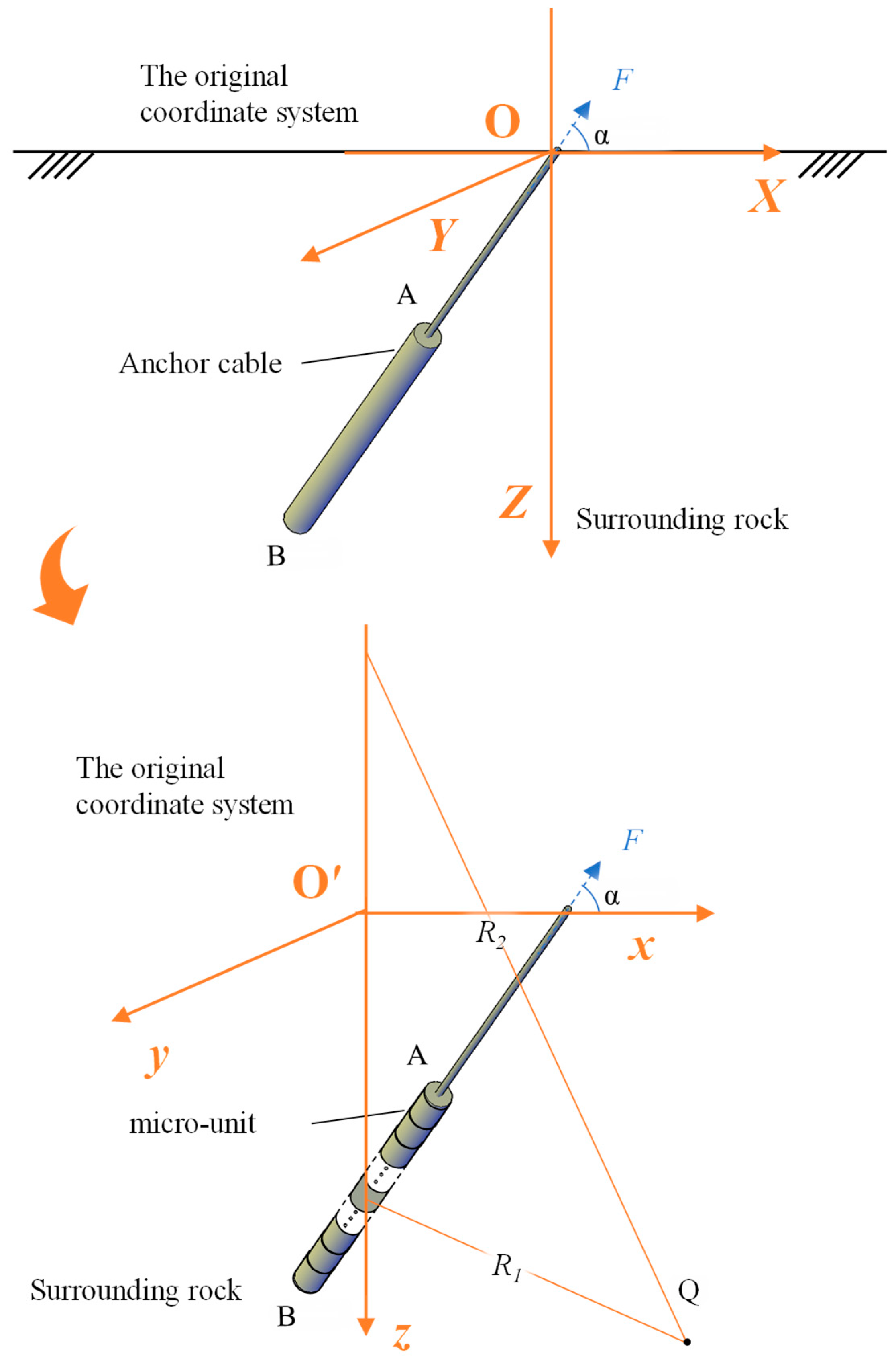
As shown in Figure 1, the inclined anchor bolt is positioned in relatively level terrain. Correspondence between physical quantities and symbols, as shown in Table 1. Point O is the intersection of the free segment of the anchor bolt and the ground surface; Point A is the boundary between the anchorage segment and the free segment; Point B is the endpoint of the anchorage segment; A’ and B’ are the projections of A and B, respectively. lOA is the free segment length of the anchor bolt, and lAB is the anchorage segment length. According to the superposition principle, the displacement of the surrounding rock is the vector sum of the displacements caused by the overburden pressure P, pulling force F, self-gravity G, and surrounding rock friction. In practical engineering applications, the self-weight of the anchor bolt is often found to be much smaller than the axial pulling force F, and it is neglected in subsequent calculations.
The model is derived by applying Mindlin’s solution for internal concentrated forces in a semi-infinite solid to inclined anchor bolts. In the present study, the displacement prediction model for the anchor bolt is derived under the following assumptions (grounded in Mindlin’s (1936) theory and practical geotechnical constraints [27]): (1) surrounding rock and grout are homogeneous, isotropic elastic materials of the same type; (2) the anchor bolt is fully bonded to surrounding rock with no slippage; (3) surrounding rock satisfies plane strain conditions and is simplified as a semi-infinite body (the influence range of the anchor bolt is far smaller than the surrounding rock’s overall dimensions, neglecting boundary effects). Due to symmetric loading and boundary conditions, the problem is simplified to two-dimensional plane strain analysis in the vertical plane containing the bolt’s centerline (Figure 2). A Cartesian coordinate system (O-XYZ) is established with O as the origin: the XOY plane is horizontal (X-axis parallel to A’B’, positive from B’ to A’), and the positive Z-axis extends into the surrounding rock.
As shown in Figure 2, the anchorage segment of the anchor bolt is discretized into n (n > 1) micro-units for mechanical analysis. According to the principle of vector superposition, the total displacement at any point Q is the vector sum of the displacements induced by all micro-units at that point. To facilitate a detailed analysis of the i-th micro-unit, the original coordinate system O-XYZ is translated along the x-axis to place the micro-unit on the z-axis (new coordinate system O’-xyz). For an arbitrary point Q (x, y, z), its new coordinates in the new system are:
x = X + l tan α ,   y = Y ,   z = Z
where α is the anchor bolt inclination angle (the angle between the anchor bolt and the horizontal plane), and l is the distance from the micro-unit to the ground surface.
The i-th micro-unit bears two force components: horizontal component (the along x-axis fx) and normal component (along the z-axis fz). By vector decomposition, the two force components can be calculated as follows, i.e.,
f x = f cos α ,
f z = f sin α
where f is the resultant force of the micro-unit.
Based on Mindlin’s solution for internal horizontal concentrated forces in a semi-infinite solid, the displacement of point Q caused by the component force (fx) of the i-th micro-unit is derived in three steps, i.e.,
Define   R 1 = x 2 + y 2 + z l 2 , R 1 = x 2 + y 2 + z + l 2 . Gρ is the surrounding rock shear modulus, and μ is the surrounding rock Poisson’s ratio.
a: x-direction displacement (ux)
u x = f x 16 π G ρ ( 1 μ ) 3 4 μ R 1 + 1 R 2 + x 2 R 1 3 + ( 3 4 μ ) x 2 R 2 3 + 2 l z R 2 3 1 3 x 2 R 2 2 + 4 ( 1 μ ) ( 1 2 μ ) R 2 + z + l 1 x 2 R 2 R 2 + z + l
b: y-direction displacement (vx)
v x = f x x y 16 π G ρ ( 1 μ ) 1 R 1 3 + 3 4 μ R 2 3 6 l z R 2 5 4 ( 1 μ ) ( 1 2 μ ) R 2 R 2 + z + l 2
c: z-direction displacement (wx)
w x = f x x 16 π G ρ ( 1 μ ) z l R 1 3 + ( 3 4 μ ) ( z l ) R 2 3 6 l z z + l R 2 5 + 4 ( 1 μ ) ( 1 2 μ ) R 2 R 2 + z + l
where ux, vx, and wx are displacements of the point Q along the x-axis, y-axis, and z-axis, respectively, caused by the x-direction component force of the micro-unit. Gρ is the shear modulus, μ is Poisson’s ratio of the surrounding rock.
Similarly, based on Mindlin’s solution for internal normal concentrated forces in a semi-infinite solid, the displacement of point Q caused by the component force (fz) of the i-th micro-unit can be expressed as follows, i.e.,
a: x-direction displacement (uz)
u z = f z x 16 π G ρ ( 1 μ ) z l R 1 3 + ( 3 4 μ ) ( z l ) R 2 3 4 ( 1 μ ) ( 1 2 μ ) R 2 R 2 + z + l + 6 l z ( z + l ) R 2 5
b: y-direction displacement (vz)
v z = f z y 16 π G ρ ( 1 μ ) z l R 1 3 + ( 3 4 μ ) ( z l ) R 2 3 4 ( 1 μ ) ( 1 2 μ ) R 2 R 2 + z + l + 6 l z ( z + l ) R 2 5
c: z-direction displacement (wz)
w z = f z 16 π G ρ ( 1 μ ) 3 4 μ R 1 + 8 ( 1 μ ) 2 ( 3 4 μ ) R 2 + z l 2 R 1 3 + ( 3 4 μ ) ( z + l ) 2 2 l z R 2 3 + 6 l z ( z + l ) 2 R 2 5
The total displacement of the point Q caused by the load from the i-th micro-unit is the sum of displacements from fx and fz, i.e.,
a: The displacements of the point Q along the x-axis caused by the i-th micro-unit (uf):
u f = u x + u z
b: The displacements of the point Q along the y-axis caused by the i-th micro-unit(vf):
v f = v x + v z
c: The displacements of the point Q along the z-axis caused by the i-th micro-unit(wf):
w f = w x + w z
Substituting X = 0, Y = 0, and Z = 0 into the Equations (1)–(12) gives the displacement of the point O, i.e.,
a: The displacements of the point O along the x-axis (uO):
u O = f sin α 4 l π G ρ 2   cos 3 α
b: The displacements of the point O along the y-axis (vO):
v O = 0
c: The displacements of the point O along the z-axis (wO):
w O = f sin α 4 l π G ρ 1 2 μ + 2 sin 3 α
The total displacement of the point O:
δ f = k f 2 l π
where k = sin α 2 G ρ 4 cos 6 α + 1 2 μ + 2 sin 3 α 2 is the inclination angle coefficient of the anchor bolt.
Based on Hooke’s law, the following equation can be obtained, i.e.,
E c A S h δ f d z = h F h 2 π r τ d z d z
where τ is the shear stress, r is the grouting hole radius, Eα is the elastic modulus of the anchor bolt, and F is the pulling force of the anchor bolt. Substituting Equation (16) into Equation (17) results in the following equation, i.e.,
k E a A S r h τ z d z = h F h 2 π r τ d z d z
Taking the third derivative of z with respect to τ on both sides of Equation (18) yields the differential equation for the shear stress, i.e.,
τ + K τ z + 2 K τ = 0
where K = 2 π E a A k .
With boundary conditions τ z = 0 = 0 and τ z = 0 , the expression for the shear stress distribution along the anchorage segment can be calculated, i.e.,
τ z = F K 2 π r z e 1 2 K h 2 z 2
where h is the distance from the boundary between the anchorage segment and the free segment to the ground surface, and z > h.
The expression for the axial force f along the anchorage segment lAB can be derived as follows, i.e.,
f l A B = F e 1 2 K h 2 l A B sin α 2

2.2. Displacement Solution for Anchor Bolts Under Pulling Force

The resultant force on each micro-element can be obtained via Equation (21). Subsequently, by substituting Equations (10)–(12) in accordance with the principle of vector superposition, the displacement of the anchor bolt under tensile pull can be further calculated: a: The displacements along the x-axis (u):
u = u f d l A B
b: The displacements along the y-axis (v):
v = v f d l A B
c: The displacements along the z-axis (w):
w = v f d l A B
The total displacement of the anchor bolt caused by the pulling force can be expressed, i.e.,
s = u 2 + v 2 + w 2
where s is the total displacement of the anchor bolt.

3. Experimental Validation

To validate the proposed model in this study, the theoretical displacement values of rock bolts under corresponding working conditions were calculated by substituting the experimental parameters from three sets of literature into the model. Specifically, the parameters were derived from the work of You [31], Cheng et al. [23], and Nourizadeh et al. [8]. A comparative analysis was conducted between the theoretically calculated values obtained from the proposed model and the experimental data reported in the aforementioned literature, as shown in Table 2.
It can be observed from Table 2 that the theoretical displacement values of rock bolts calculated by the proposed model in this paper exhibit good consistency with the experimental data reported in the literatures. For the 88° inclination angle reported in You (2004) [31], the relative error between the theoretical and experimental values is within 1%. For the experimental conditions of Cheng et al. (2022) [23], the model’s deviation is less than 5% overall, with respective values of 2.4% (15°) and 2.1% (20°). Additionally, the theoretical error is 2.7% when compared with the experimental data of Nourizadeh et al. (2025) [8].
To evaluate the impact of measurement errors on model output, a sensitivity analysis was conducted. The input parameters (elastic modulus E, Poisson’s ratio μ, anchorage length lAB) were varied by ±5%, and the resulting displacement changes were calculated, as shown in Table 3.
As shown in Table 3, when the input parameters (e.g., elastic modulus E, Poisson’s ratio μ, anchorage length lAB) exhibit a 5% measurement deviation, the maximum variation in displacement calculated by the proposed model is only 4.1%. This observation indicates that even when minor measurement uncertainties exist in input parameters under practical engineering conditions, the calculated displacement results do not exhibit significant deviations. Such outcomes further verify the robustness of the model to a certain extent.

4. Discussion

Based on the displacement prediction model proposed in this study, the correlation laws between anchor bolt displacement and key factors (inclination angle, elastic modulus, and Poisson’s ratio of surrounding rock) can be clarified. Meanwhile, the axial force attenuation characteristics and shear stress distribution patterns of inclined anchor bolts can be obtained, which provides certain theoretical support for engineering designs such as anchor bolt inclination angle selection and anchorage parameter optimization.

4.1. Effect of Inclination Angle on Anchor Bolt Displacement

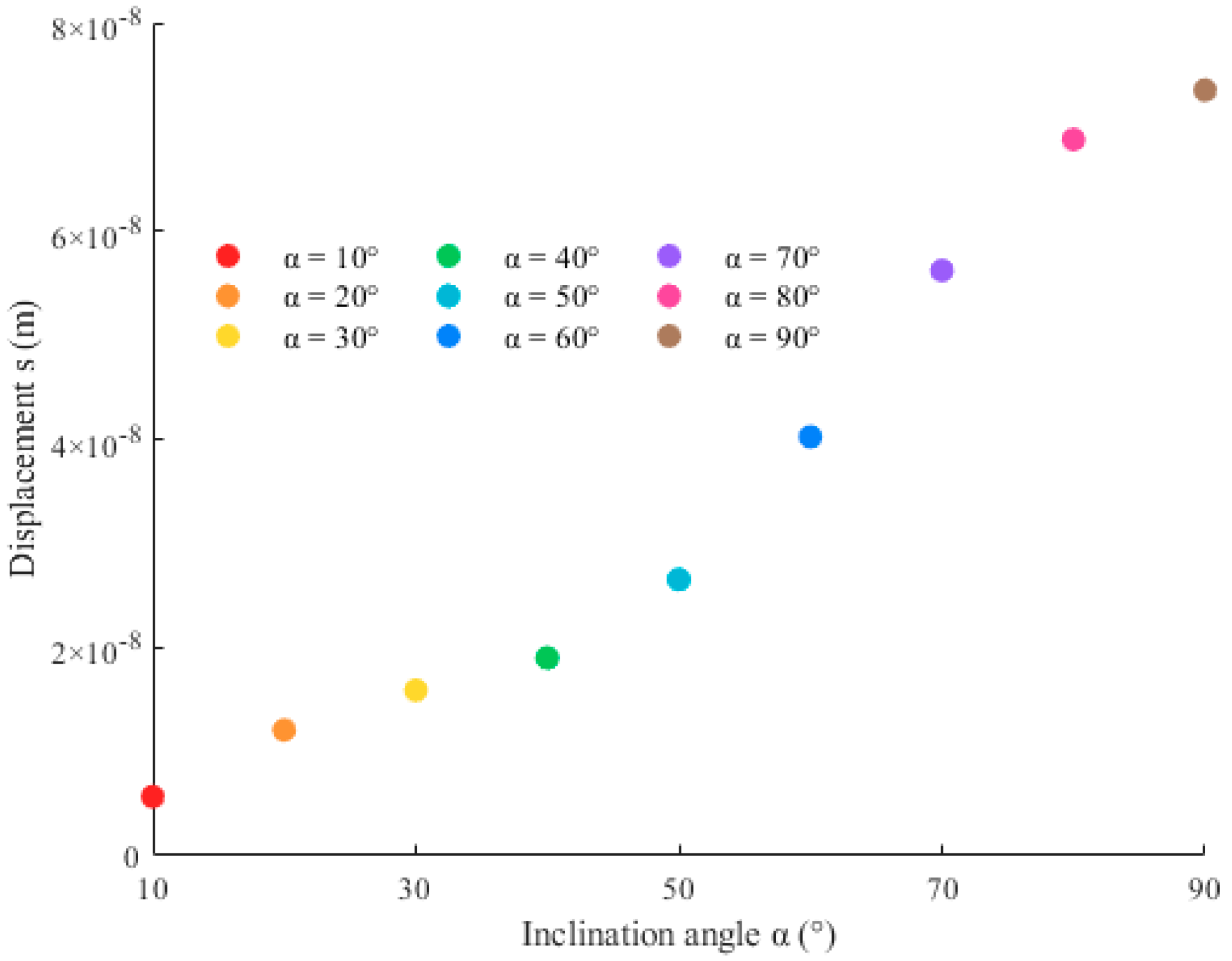
Figure 3 shows that the displacement of the anchor bolt increases with inclination angle, with a sharp growth in the 50–70° range (displacement increases about 0.8 mm (60%), when the angle rises from 50° to 70°). This phenomenon can be attributed to two main factors. On one hand, as inclination increases, the horizontal component of the pulling force decreases, reducing the vertical normal pressure from surrounding rock on the bolt; On the other hand, lower normal pressure decreases the bolt-surrounding rock friction, leading to larger displacement. In the 50–70° range, the vertical component of the pulling force rises rapidly, further reducing normal pressure and causing a “sensitivity jump” in displacement.
In practical engineering design, careful attention should be paid to the inclination angle of anchor bolts, with particular emphasis on the sensitive range of 50–70°. The 50–70° inclination range should be avoided if displacement control is critical. If this range is unavoidable, the anchorage length can be increased to enhance the frictional force between the anchor bolt and the surrounding rock.

4.2. The Shear Distribution of the Anchor Bolt

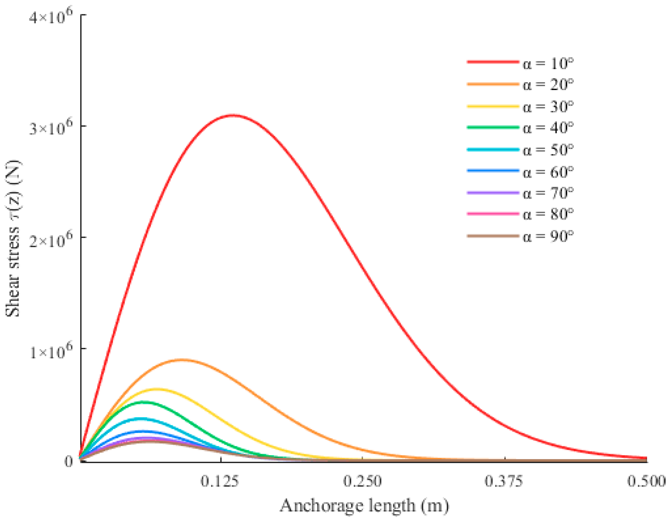
Figure 4 shows that shear stress distributions exhibit single-peak characteristics: zero at the start of the anchorage segment, rising to a peak, then decreasing to zero. As the inclination angle increases, the peak shear stress decreases. This is because higher inclination reduces surrounding rock normal pressure, lowering shear stress and shortening the effective stress transfer range.

4.3. The Axial Force Distribution of the Anchor Bolt

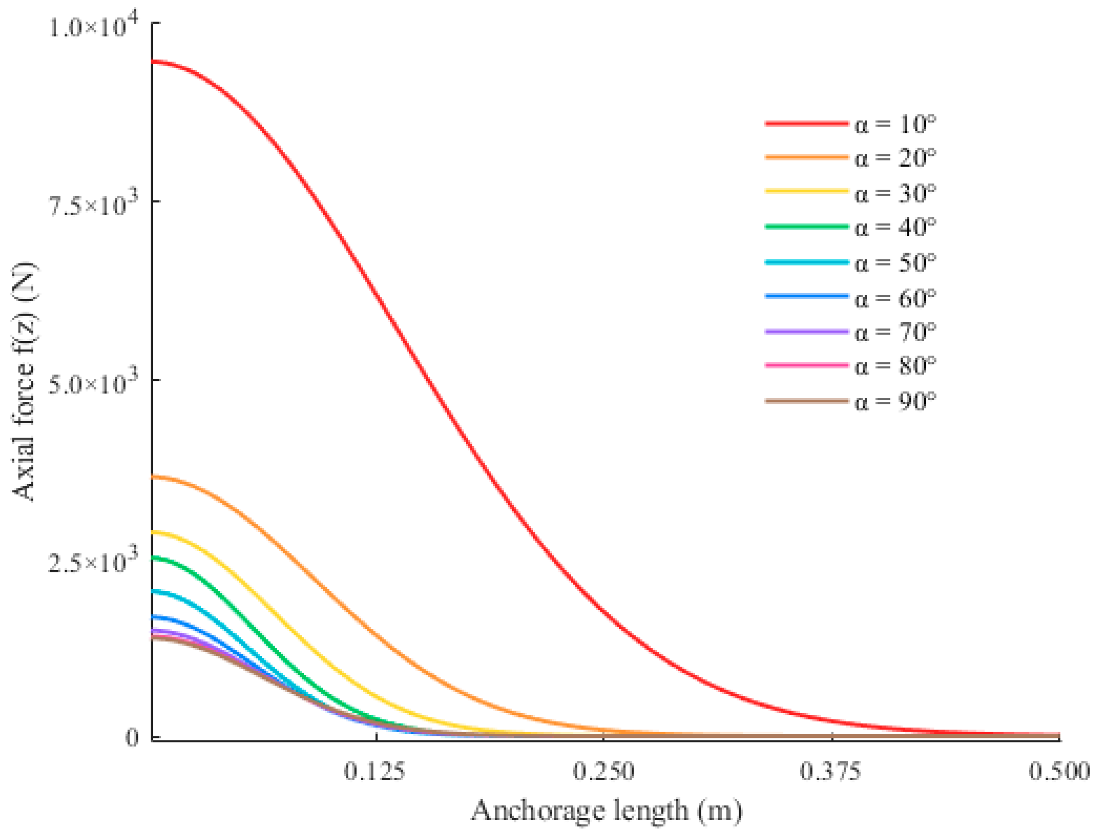
Figure 5 shows that axial force decreases exponentially along the anchorage segment, consistent with previous studies [6,9,14]. Key observations: (1) initial axial force decreases with inclination (e.g., 13.5 MN at 10° vs. 10.2 MN at 70°); (2) the effective anchorage range (where axial force >1% of initial value) shrinks with inclination. For example, the initial axial force at 10° is about 2.5 times that at 70°, and the effective range at 10° is about 1.8 times that at 70°. This confirms that reducing inclination can extend the effective anchorage range and improve load transfer efficiency.

4.4. Influence of Poisson’s Ratio and Shear Modulus of Surrounding Rock on the Anchor Bolt Displacement

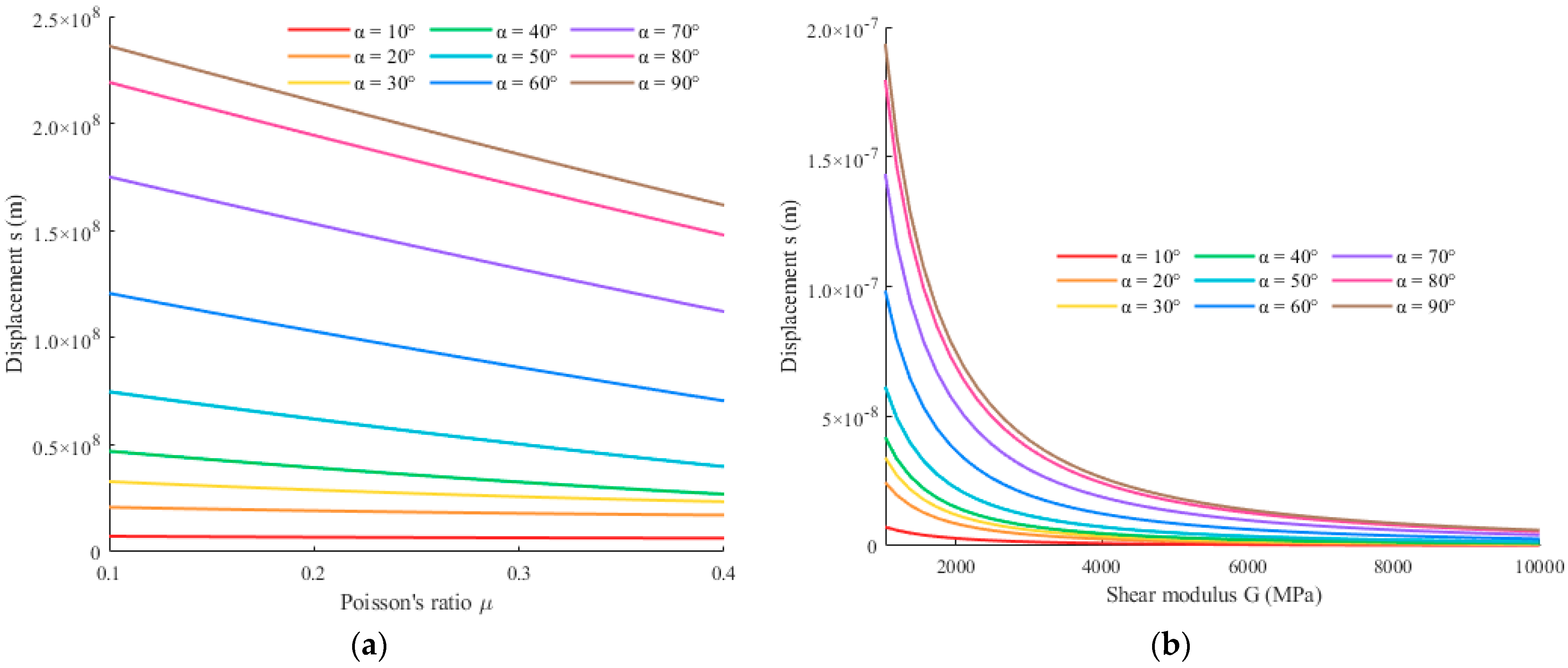
Figure 6a illustrates that the displacement of the anchor bolt decreases with an increase in the Poisson’s ratio (μ) of the surrounding rock. This is because higher μ increases lateral constraint, reducing surrounding rock deformation. The effect is more pronounced for high inclinations (e.g., 70°) than low inclinations (e.g., 30°), as high-inclination bolts rely more on lateral constraint to control displacement.
As shown in Figure 6b, the displacement of the anchor bolt decreases with the shear modulus of surrounding rock increasing. The shear modulus reflects the inherent capacity of the surrounding rock to resist shear deformation: a larger shear modulus corresponds to a weaker tendency of the surrounding rock to undergo shear slip under the forces exerted by the anchor bolt, thereby resulting in smaller displacement of the anchor bolt. The displacement drops sharply when Gρ < 3.0 GPa, then stabilizes when Gρ > 3.0 GPa. For example, at 70° inclination, displacement decreases by about 0.8 mm (50%) when Gρ increases from 0.2 GPa to 1.5 GPa. This is because Gρ reflects the surrounding rock’s shear resistance—higher Gρ reduces shear deformation under bolt forces.
From the above analysis, in anchor bolt design, priority should be given to installing bolts in the surrounding rock with a relatively high shear modulus. Furthermore, reducing the inclination angle of the anchor bolt can enhance the stability of the anchorage system. Specifically, when the installation parameters of the anchor bolt (e.g., anchorage length, pre-tightening force) are fixed, appropriately reducing the inclination angle can effectively control the displacement of the anchor bolt and further enhance the stability of the support system.

4.5. Comparison with Engineering Standards

To verify the applicability and rationality of the inclined anchor displacement prediction model proposed in this study for practical engineering design, the model’s prediction results were compared with the requirements of two core standards widely used in geotechnical engineering: Europe’s Geotechnical Design Standard (Eurocode 7, EN 1997-1:2004 [32]) and China’s Technical Code for Design of Building Slope Engineering (GB 50330-2013 [33]).
Eurocode 7 requires anchor displacement for permanent slopes to be <5 mm. Using the dataset from Nourizadeh et al. (2025) [8] (anchorage length: 150 mm; rock elastic modulus: 32 GPa; confining pressure: 5 MPa), the model calculates a displacement of 1.91 mm—far below the 5 mm limit. This confirms compliance with the standard. With significant safety redundancy (1.91 mm is only 38.2% of the limit), the safety factor can be moderately reduced (e.g., from 1.5 to 1.3–1.4) while ensuring bearing capacity, optimizing material usage, and cutting costs.
GB 50330-2013 specifies a minimum anchorage length of 5 m for rock slopes (based on conservative design). The proposed model was used to calculate the anchorage length requirement under different inclination angles: When the slope inclination is 70° (classified as a steep slope with high displacement sensitivity), the model prediction shows that the anchorage length must be extended to 6 m to control displacement within 2 mm; in contrast, when the slope inclination is 10° (a gentle slope with low displacement sensitivity), an anchorage length of only 5 m is sufficient to meet the requirement of displacement smaller than 2 mm. This aligns with the standard’s conservative philosophy. It also enables targeted design: no extra length is needed for gentle slopes (e.g., 10°) if 5 m meets displacement demands; for steep slopes (e.g., 70°), extend length as predicted—avoiding over-design and improving material efficiency.

5. Conclusions

In this paper, a novel theoretical model for predicting the displacement of inclined anchor bolts was developed based on Mindlin’s solution. The validity of the displacement prediction model is verified by comparison with the pulling experimental data from existing literature. The value calculated by the displacement prediction model shows good agreement with the reported field experimental value. The main conclusions are as follows:
(1).
A novel displacement prediction model for inclined anchor bolts was derived based on Mindlin’s solution, explicitly incorporating inclination angle (0° < α < 90°) into force decomposition and displacement superposition.
(2).
The inclination angle of the anchor bolt exerts a significant influence on its displacement. The displacement of the anchor bolt increases with inclination angle, with a sharp growth in the 50–70° range. And both peak shear stress and initial axial force decrease with increasing inclination angle.
(3).
Validation with three experimental datasets [8,23,31] shows that the model’s relative errors are within 5%. Even if minor measurement uncertainties of input parameters exist in practical engineering scenarios, the calculated displacement results will not undergo significant deviations, confirming its reliability.
The anchor bolt displacement prediction model proposed in this study not only aids scholars in better understanding the relationship between anchor bolt inclination angle and displacement, but also aligns with the general requirement in anchor bolt design—namely, that anchor bolts operate within the elastic range. Notably, by quantifying the correlation between inclination angle and displacement, the model can be integrated into the anchor bolt design process, providing a practical reference for determining a suitable anchor bolt inclination angle that meets engineering needs. Derived from Mindlin’s solution (which is predicated on idealized assumptions), the model is applicable exclusively to anchor bolts in the elastic working stage and is inapplicable to those with obvious failure. Additionally, for non-homogeneous surrounding rock (e.g., rock masses with a certain joint distribution), the model may exhibit certain errors in predicting anchor bolt displacement. Future research will focus on relaxing the Mindlin solution’s idealized assumptions (e.g., incorporating the effects of non-homogeneous or jointed surrounding rock) to improve the model’s adaptability to complex engineering conditions and expand its application in anchor bolt support design.

Author Contributions

The authors confirm contribution to the paper as follows: study conception and design: Z.Z., G.X. and B.X.; data collection: G.X. and B.X.; analysis and interpretation of results: G.X.; draft manuscript preparation: Z.Z., G.X. and B.X. All authors have read and agreed to the published version of the manuscript.

Funding

This research was supported by Fundamental Research Funds for the Central Universities with (Grant No. JZ2024HGTB0206).

Data Availability Statement

The data used in this study were obtained from previously published literature. Specifically, the datasets were derived from You (2004) [31], Cheng et al. (2022) [23], and Nourizadeh et al. (2025) [8]. No new primary or processed datasets were generated in the current study. The original data can be accessed by referring to the aforementioned references (please see the References section for full citation information).

Conflicts of Interest

The authors declare that this study received funding from Anhui Road & Bridge Engineering Co., Ltd. (Grant No.: W2022JSFW0602). The funder was not involved in the study design, collection, analysis, interpretation of data, the writing of this article or the decision to submit it for publication.

References

  1. Grindheim, B.; Li, C.C.; Høien, A.H. Full-scale pullout tests of rock anchors in a limestone quarry focusing on bond failure at the anchor-grout and grout-rock interfaces. J. Rock Mech. Geotech. Eng. 2023, 15, 2264–2279. [Google Scholar] [CrossRef]
  2. Ouyang, J.; Shi, X.; Qiu, X.; Zhang, Z.; Li, Z. Bond length and interface failure mechanism of anchor bolt under continuous radial pressure conditions. Int. J. Min. Sci. Technol. 2025, 35, 231–247. [Google Scholar] [CrossRef]
  3. Chen, W.Q.; Jia, L.Y. Analytical model of bolt shear resistance considering progressive yield of surrounding material. SN Appl. Sci. 2022, 4, 42. [Google Scholar] [CrossRef]
  4. Brown, E.T. Rock engineering design of post-tensioned anchors for dams—A review. J. Rock Mech. Geotech. Eng. 2015, 7, 1–13. [Google Scholar] [CrossRef]
  5. Fu, M.; Huang, S.; Fan, K.; Liu, S.; He, D.; Jia, H. Study on the relationship between the maximum anchoring force and anchoring length of resin-anchored bolts of hard surrounding rocks based on the main slip interface. Constr. Build. Mater. 2023, 409, 134000. [Google Scholar] [CrossRef]
  6. Xu, X.; Tian, S. Load transfer mechanism and critical length of anchorage zone for anchor bolt. PLoS ONE 2020, 15, e0227539. [Google Scholar] [CrossRef] [PubMed]
  7. Zhou, C.; Hu, Y.; Xiao, T.; Ou, Q.; Wang, L. Analytical model for reinforcement effect and load transfer of pre-stressed anchor bolt with bore deviation. Constr. Build. Mater. 2023, 379, 131219. [Google Scholar] [CrossRef]
  8. Nourizadeh, H.; Mirzaghorbanali, A.; McDougall, K. Exploring the axial performance of protective sheathed rock bolts through large-scale testing. Tunn. Undergr. Space Technol. 2025, 155, 106157. [Google Scholar] [CrossRef]
  9. Fang, G.W.; Zhu, Y.P.; Ye, S.H.; Huang, A.P. Analysis of force and displacement of anchor systems under the non-limit active state. Sci. Rep. 2022, 12, 1306. [Google Scholar] [CrossRef]
  10. Ye, S.; Chen, J. Reliability analysis of slope reinforced by frame anchors considering multi-anchor failure. Arab. J. Geosci. 2022, 15, 37. [Google Scholar] [CrossRef]
  11. Zhu, B.; Zhou, C.; Jiang, N. Dynamic characteristics and safety control of mortar bolts under tunnel blasting vibration loads. Tunn. Undergr. Space Technol. 2023, 135, 105005. [Google Scholar] [CrossRef]
  12. Zheng, Y.; Wang, R.; Chen, C.; Sun, C.; Ren, Z.; Zhang, W. Dynamic analysis of anti-dip bedding rock slopes reinforced by pre-stressed bolts using discrete element method. Eng. Anal. Bound. Elem. 2021, 130, 79–93. [Google Scholar] [CrossRef]
  13. Li, X.; Si, G.; Oh, J.; Corbett, P.; O’Sullivan, T.; Xiang, Z.; Aziz, N.; Mirzaghorbanali, A. Effect of pretension on the performance of bolt bolts and its optimisation in underground coal mines with various geological conditions. Int. J. Rock Mech. Min. Sci. 2022, 154, 105076. [Google Scholar] [CrossRef]
  14. Ma, H.; Chen, L.; Tan, X.; Qian, J.; Lu, Z. Theoretical dynamic displacement analysis for rock bolt with surrounding rock-soil body. Int. J. Rock Mech. Min. Sci. 2021, 141, 104698. [Google Scholar] [CrossRef]
  15. Yue, Z.; Li, A.; Wang, P.; Wang, P. An analytical analysis for the mechanical performance of fully-grouted roc bolts based on the exponential softening model. Int. J. Rock Mech. Min. Sci. Technol. 2022, 32, 981–995. [Google Scholar] [CrossRef]
  16. Li, D.; Cai, M.; Masoumi, H. A constitutive model for modified bolt bolts exhibiting cone-shaped failure mode. Int. J. Rock Mech. Min. Sci. 2021, 145, 104855–104864. [Google Scholar] [CrossRef]
  17. Martín, L.; Tijani, M.; Hadj-Hassen, F.; Noiret, A. Assessment of the bolt-grout interface behaviour of fully grouted rockbolts from laboratory experiments under axial loads. Int. J. Rock Mech. Min. Sci. 2013, 63, 50–61. [Google Scholar] [CrossRef]
  18. Chen, J.; Li, D. Numerical simulation of fully encapsulated rock bolts with a tri-linear constitutive relation. Tunn. Undergr. Space Technol. 2022, 120, 104265. [Google Scholar] [CrossRef]
  19. Liang, L.; Zou, X.; Liu, J. Approximate analytical algorithm for pull-out resistance-displacement relationship of combined anchor system. Eng. Fail. Anal. 2024, 166, 13. [Google Scholar] [CrossRef]
  20. Jia, H.; Wang, Y.; Liu, S.; Li, Y.; Shao, R.; Wang, G.; Guo, Z.; Wang, L. Experimental study on double cuneiform reamed anchorages for bolt bolt boreholes in soft rock. Int. J. Rock Mech. Min. Sci. 2022, 158, 105198. [Google Scholar] [CrossRef]
  21. Lin, H.; Zhong, W.W.; Xiong, W.; Tang, W.Y.; Cao, P. Effect of bolt length and slope rate on optimum anchorage angle. Chin. J. Geotech. Eng. 2014, 36, 7–11. [Google Scholar] [CrossRef]
  22. Sun, C.; Chen, C.; Zheng, Y.; Yuan, J. Assessing the stability of bolt-reinforced high bedding rock slopes against rotational bi-planar failure. Rock Mech. Rock Eng. 2023, 56, 1697–1715. [Google Scholar] [CrossRef]
  23. Cheng, Y.; Xu, Y.; Wang, L.; Wang, L. Stability of expansive soil slopes reinforced with anchor bolts based on rotational-translational mechanisms. Comput. Geotech. 2022, 146, 104747. [Google Scholar] [CrossRef]
  24. Zhang, J.; Niu, J.; Fu, X.; Cao, L.; Xie, Q. Shaking table test of seismic responses of anchor bolt and lattice beam reinforced slope. J. Mt. Sci. 2020, 17, 1251–1268. [Google Scholar] [CrossRef]
  25. Al-Shayea, N.A. Displacement of rods during pullout failure of rock anchors: A case study. Geotech. Geol. Eng. 2024, 42, 5117–5141. [Google Scholar] [CrossRef]
  26. Mindlin, R.D. Force at a Point in the Interior of a Semi-Infinite Solid. Physics 1936, 7, 195–202. [Google Scholar] [CrossRef]
  27. Zheng, B.; Bayat, M.; Shi, Y.; Cao, M.; Jiang, Y.; Qian, X.; Sumarac, D. A prognostic model of side friction of rock bolt anchoring section based on associated flow law. Kuwait J. Sci. 2025, 52, 100374. [Google Scholar] [CrossRef]
  28. Nourizadeh, H.; Mirzaghorbanali, A.; Serati, M.; Mutaz, E.; McDougall, K.; Aziz, N. Failure characterization of fully grouted rock bolts under triaxial testing. J. Rock Mech. Geotech. Eng. 2024, 16, 778–789. [Google Scholar] [CrossRef]
  29. Zhang, N.; Lu, F.; Li, C.; Guo, H.; Yin, S.; Liu, Y.; Li, Q. Shear stress distribution of fully grouted rockbolts under tensile loads. Int. J. Geomech. 2025, 25, 04025022. [Google Scholar] [CrossRef]
  30. Fu, X.; Li, Q.; Liu, H.; Wang, L.; Liu, X. Bearing capacity characteristic analysis of anti-floating bolts in unsaturated soil based on mindlin solution. Indian Geotech. J. 2025, 55, 1044–1053. [Google Scholar] [CrossRef]
  31. You, C.A. Study on static load test of group anchors. Rock Soil. Mech. 2004, 25, 383–385. [Google Scholar] [CrossRef]
  32. EN 1997-1:2004; European Committee for Standardization. Eurocode 7: Geotechnical Design—Part 1: General Rules. CEN: Brussels, Belgium, 2004.
  33. GB 50330-2013; Ministry of Housing and Urban—Rural Development of the People’s Republic of China. Technical Code for Building Slope Engineering. China Architecture & Building Press: Beijing, China, 2013.
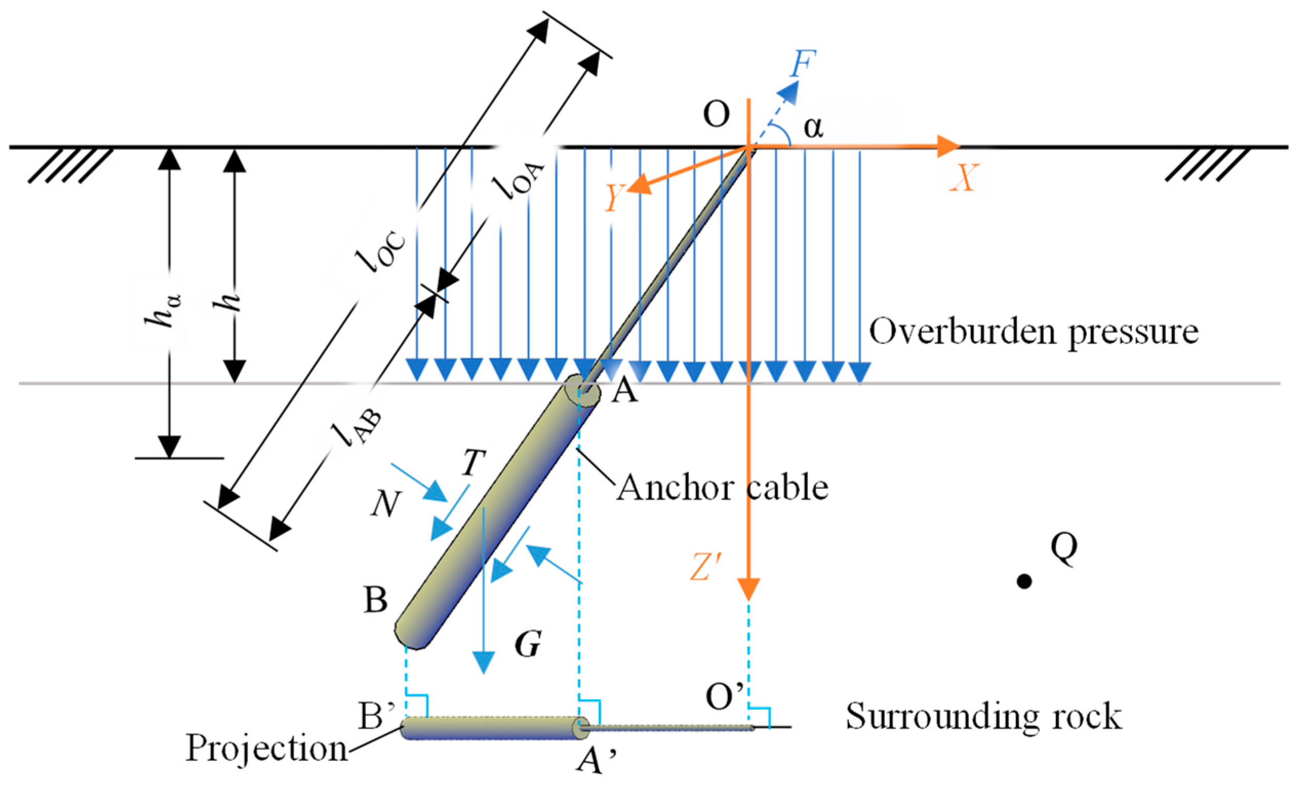
Figure 1. Mechanical model of an inclined anchor bolt.
Jmse 13 01828 g001
Figure 2. Analysis model.
Jmse 13 01828 g002
Figure 3. Relationship between anchor bolt inclination angle and displacement.
Jmse 13 01828 g003
Figure 4. Shear stress distribution along the anchorage segment.
Jmse 13 01828 g004
Figure 5. Axial force distribution along the anchorage segment.
Jmse 13 01828 g005
Figure 6. Influence of Poisson’s ratio and shear modulus of surrounding rock on anchor bolt displacement: (a) Poisson’s ratio; (b) shear modulus.
Jmse 13 01828 g006
Table 1. Correspondence between physical quantities and symbols.
SymbolPhysical QuantityUnit
αInclination angle°
GρShear modulus of surrounding rockGPa
EElastic modulus of surrounding rockGPa
μPoisson’s ratio of the surrounding rock/
EαElastic modulus of the anchor boltGPa
fResultant force of the micro-unitN
fxx-axis force component of micro-unitN
fzz-axis force component of the micro-unitN
FPulling force of the anchor boltN
lABAnchorage segment lengthm
lCoordinate of the micro-unit along the z-axis./
uODisplacements of the point O along the x-axism
vODisplacements of the point O along the y-axism
wODisplacements of the point O along the z-axism
uxDisplacement of point Q caused by fx along the x-axism
vxDisplacement of point Q caused by fx along the y-axism
wxDisplacement of point Q caused by fx along the z-axism
uzDisplacement of point Q caused by fz along the x-axism
vzDisplacement of point Q caused by fz along the y-axism
wzDisplacement of point Q caused by fz along the z-axism
ufDisplacements of the point Q along the x-axis caused by the i-th micro-unitm
vfDisplacements of the point Q along the y-axis caused by the i-th micro-unitm
wfDisplacements of the point Q along the z-axis caused by the i-th micro-unitm
τShear stress/
rGrouting hole radiusm
ASCross-sectional area of anchor boltm2
δfTotal displacements of the micro-unitm
uDisplacements of the anchor bolt along the x-axis
vDisplacements of the anchor bolt along the y-axis
wDisplacements of the anchor bolt along the z-axis
hDistance from the boundary between the anchorage segment and the free segment to the ground surface
sTotal displacement of the anchor bolt
Table 2. Parameters and validation results.
ReferenceInclination Angle of Centerline α (°)Elastic Modulus of Surrounding Rock
E (GPa)
Elastic Modulus of the Bolt
Ea (GPa)
Anchorage Length
lAB (m)
Poisson’s Ratio μPulling Force
F (MN)
Displacement of
Anchor Bolt (mm)
Relative Error (%)
Experimental ValueTheoretical Value
You (2004) [31]881.221060.313.91.481.470.6
Cheng et al. (2022) [23]150.820580.358.52.122.172.4
Cheng et al. (2022) [23]200.820580.358.52.352.442.1
Nourizadeh et al. (2025) [8]301.521050.2810.21.861.912.7
Table 3. Sensitivity analysis results (based on You’s (2004) [31] dataset).
ParameterVariationCalculated Displacement (mm)Displacement Change (%)
NameValue
Elastic modulus of surrounding rock E1.2 GPa+5% (1.26 GPa)1.41−4.1
−5% (1.14 GPa)1.53+4.1
Poisson’s ratio of the surrounding rock μ0.3+5% (0.315)1.45−1.4
−5% (0.285)1.49+1.4
Anchorage length lAB6 m+5% (6.3 m)1.43−2.7
−5% (5.7 m)1.51+2.7
Disclaimer/Publisher’s Note: The statements, opinions and data contained in all publications are solely those of the individual author(s) and contributor(s) and not of MDPI and/or the editor(s). MDPI and/or the editor(s) disclaim responsibility for any injury to people or property resulting from any ideas, methods, instructions or products referred to in the content.