Abstract
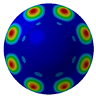
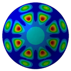
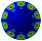
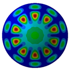
A disc-shaped double-layer shell structure reinforced by stiffeners is introduced for underwater gliders. Based on the finite element method integrated with automatic matching layer (FEM/AML) technology and the direct boundary element method (DBEM), the acoustic response of a disc-shaped double-layer shell with six longitudinal ribs within the frequency range of 10–500 Hz is obtained. The resonant frequencies of the sound pressure level (SPL) correlate with the structural–acoustic modes. At resonance frequencies, the acoustic directivity and spatial sound pressure distribution of the double-layer shell exhibit symmetry relative to the mid-cross-section. The influence of longitudinal rib counts on vibro-acoustic behavior is investigated. The analysis results of frequency–spatial spectrum for radiated sound pressure reveal that the resonant frequencies migrate to the mid-high frequency with increases in the longitudinal rib quantity.
1. Introduction
The vibration of the internal mechanical structure in underwater gliders generates radiated noise during ascent and descent phases. The noise not only compromises their target recognition capability but also degrades their stealth performance. Research on the vibro-acoustic coupling characteristics underwater not only helps to enhance the acoustic stealth property of the structures but also improves the overall performance of the equipment [1].
Conventional underwater gliders typically employ slender, single-layer cylindrical designs, which exhibit inherent limitations, including large turning radius and poor maneuverability [2,3]. In contrast, disc-shaped configurations have gained research interest owing to their high lift-to-drag ratios and superior maneuverability. Nakamura et al. [4,5] of Kyushu University developed two disc-shaped gliders, “LUNA” and “BOOMERANG”, for large-scale shallow-water monitoring. Ocean trials with prototypes were conducted focused on path planning and course control. The 3D distributed cooperative guidance model-free control method was proposed by Lu [6] to optimize path planning of disk-typed autonomous underwater gliders. Zhou [7] numerically solved motion control equations via the Runge–Kutta method, demonstrating that disc-shaped geometries enhance lift-to-drag ratios and substantially reduce the turning radius, thereby improving underwater maneuverability. Sun [8] characterized vibro-acoustic responses during water entry using finite element analysis, revealing that an added-mass increase from an expanded wetted surface area induces resonance frequency shifts.
Although extensive investigations have been conducted on the motion characteristics and hydrodynamic performance of disc-shaped underwater gliders, studies on acoustic characteristics remain relatively scarce. In recent years, researchers have conducted a few vibration–acoustic experiments based on models of a cylindrical shell and spherical shell with a single layer.
Wang [9] studied the radiation noise caused by the buoyance adjustment, pitch adjustment, and propeller rotation of the underwater glider based on the experiments conducted in the South China Sea. The vibration and noise reduction technique was established to eliminate the influence on the hydrophone. The advances in computational methodologies of vibro-acoustic analysis and the acoustic performance of composite material structures and FGM plates were outlined by Dash [10]. Zhao [11,12] constructed an analytical model of a partially immersed finite-length cylindrical shell by using the modal expansion method and wavenumber domain transformation method, investigating the low frequency vibro-acoustic behavior of a near-surface target. The radial vibration velocity, radiated sound pressure, and corresponding frequency–depth spectrum of the cylindrical shell is obtained during continuous descent through experimental measurements. Marsick [13] proposed a theoretical model of an infinite cylindrical shell submerged at a finite distance from a free sea surface to obtain the influence of the free sea surface and shell modes on structural and acoustic responses. Kha [14] developed analytical approaches for the purpose of researching the vibro-acoustic responses of submerged elastic structures in shallow water environments. A load-bearing, wide-bandgap star-shaped metastructure was proposed by Zhuang and Zuo [15,16], which can reduce the radiation noise (824–1500 Hz) of an underwater cylindrical shell with a minimal weight penalty. Experimental measurements established that noise-reduction bandwidths correlate directly with unit-cell bandgaps, which depend solely on geometric and material properties, remaining invariant to external acoustic conditions. Integrating the Three-dimensional Sono-elasticity Method with THAFTS software, Zou [17,18,19,20] developed a ship model incorporating acoustic cladding for low-to-mid-frequency vibro-acoustic analysis. The experimental data of a small-scale stiffened cylindrical hull and a full-scale ship in a pool basin verified the accuracy of the method. Through simulation based on software THAFTS-Acoustic and validation of experimental data, Jiang [21] examined acoustic radiation from composite laminates.
Sun [22] advanced a hybrid analytic–numerical approach to analysis the vibro-acoustic response of a combined shell with interior substructures. Tang et al. [23,24,25] studied the underwater vibration radiation noise of a submerged single-layer stiffened cylindrical shell under multiple excitations through the anechoic pool experiment. The exterior acoustic field of the ring-stiffened cylindrical shells with internal bulkheads was described through Jacobi–Ritz–spectral BEM and the spectral Kirchhoff–Helmholtz integral formula. The acoustic and vibration responses of the metamaterial plate and cavity coupling system (MPCCS) are simulated with the finite elements method by Dong [26]. Then, an experiment involving metamaterial plates is achieved in an anechoic tank in order to verify the efficacy of acoustic metamaterials in controlling low-frequency vibration and noise within the coupling system. Zhang [27] proposed a capsule composite structure for transducer design, and analyzed the influence of key structural parameters on the acoustic performance of the transducer using the finite element method. Zhao [28] evaluated the vibro-acoustic behavior of a cylindrical shell under three different conditions: individual shell, fluid-filled shell, and submerged fluid-filled shell, demonstrating that the internal fluid medium would have a significant influence on the acoustic field characteristics of cylindrical shells. The effects of various geometric and material properties (including curvature, boundary conditions, interface stiffness, and CNT distribution patterns) on the vibration behavior were systematically evaluated [29,30].
The paper proposed a disc-shaped double-lay shell with stiffeners combined with longitudinal ribs and ring ribs for an underwater glider. The vibration-radiated noise of the shell structure’s acoustic response was calculated based on the FEM/AML and DBEM approach to describe the acoustic coupling characteristics underwater. Simultaneously, the variation trend of sound pressure in the frequency domain and the spatial distribution characteristics of the radiated sound field with different numbers of ribs were analyzed.
2. Theoretical Formulations and Validation
2.1. Formulation
The radiated sound field generated by structural vibration is governed by the acoustic wave equation:
where is the Laplace operator, is the sound pressure, and represents the acoustic wave speed under small-amplitude approximations.
Applying the Fourier transform on the time variable of to obtain the spectral decomposition formula, the following is obtained:
Combining Equations (1) and (2) leads to the Helmholtz equation for harmonic excitation:
where defines the spatial variation of sound pressure at an angular frequency, is the wavenumber, and is the wavelength. Solving Equation (3) determines the radiated sound field from harmonically excited structures.
2.2. Validation
In this paper, the analytical solution for the radiation sound filed of a spherical shell under harmonic excitation is obtained. Comparisons between analytical and numerical results validates the accuracy of both the FEM/AML and DBEM methodologies. The schematic diagram of the spherical shell model is illustrated in Figure 1.
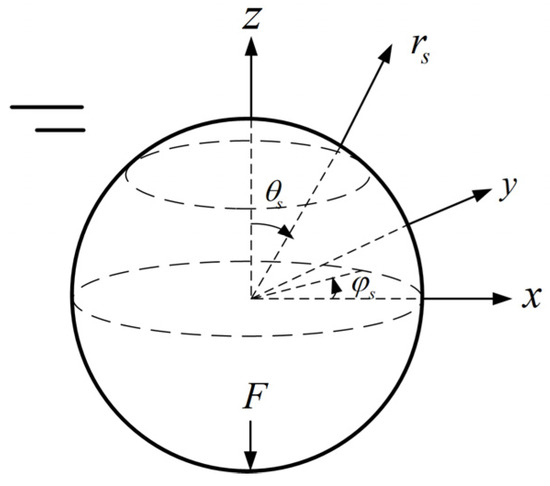
Figure 1.
Schematic of spherical shell model.
The analytical solution for the pressure of the radiated sound field of a spherical shell can be expressed as follows:
where denotes the sound pressure at the filed point (the modulus is the amplitude of sound pressure), is the spherical coordinates with their origin at the shell center, is the amplitude of the nth normal modulus of the vibration displacement of the spherical shell, is the sphere shell radius, represents the th-order Legendre polynomials, and is the th order Spherical Hankel H2 function
The sound pressure level (SPL) at distance of 1 m from the origin of the sphere can be expressed as:
The parameters of the spherical shell are shown in Table 1. The normal concentrated harmonic force of unit amplitude acts perpendicularly on the bottom of the spherical shell.

Table 1.
Parameters of spherical shell.
Figure 2 shows the comparisons of the SPL at 1 m point with angles of 180° and 90°. Both the FEM/AML and DBEM results show excellent agreement with analytical predictions. The SPL curve at monitoring point reaches the maximum at 296 Hz, 366 Hz, 426 Hz, and 476 Hz, where it is indicated that the resonance occurs. The SPL curve at monitoring point at exhibits sharp crests at frequencies of 296 Hz and 426 Hz. The slight resonant peak at 366 Hz is obtained by the method of FEM/AML. The results of SPL at point indicated that the transverse monitoring point is not sensitive to the variation of the vibration modes at frequencies of 366 Hz and 476 Hz, which is different from the vertical monitoring points . Meanwhile, compared with the DBEM, the method of FEM/AML is more sensitive to the vibro-acoustic response caused by the local modes of the shell at 366 Hz.
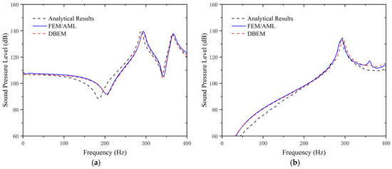
Figure 2.
SPL curves: (a) monitoring point at ; (b) monitoring point at .
Although there is a certain deviation between the simulation results and the analytical solution in the 180° direction, particularly at the first anti-resonance frequency, which might be caused by numerical discretization such as mesh division. The amplitude of sound pressure at the resonant frequency matches closely. Furthermore, the consistent trends of radiated sound pressure curves in the frequency domain proves the accuracy of the numerical approaches in predicting the vibration radiation noise of underwater structures.
3. Model of Disc-Shaped Double-Layer Shell with Stiffeners
3.1. Structural Model
The shell of the disc-shaped underwater glider adopts a full rotational symmetry structure. The disc-shaped double-layer stiffened shell is mainly composed of an outer fairing shell, inner shell, ring rib, longitudinal dysmorphism ribs, and back-up rings.
The disc-shaped glider form of the external fairing—characterized by a large radial span and short axial height—ensures a high lift-to-drag ratio during motion. A larger trailing edge of fairing can ensure the glider has a long gliding distance. The inner shell is an ellipsoidal shape, which will be equipped with a gravity adjustment device, control unit, power supply system, etc.
The shape of the longitudinal ribs is determined by the profile of the inner shell and external fairing. The longitudinal ribs are uniformly arranged along the circumferential direction of the structure, and the angle between each rib is 60°. The combination of ring ribs and longitudinal ribs partitions the space between the inner and outer shells into multiple sealed compartments. The separation configuration of the independent cabin is helpful to provide sufficient reserve buoyancy to ensure the proper function of other mechanisms if the fairing is partially damaged. The intermediate cavity accommodates the buoyancy regulation mechanism and pressure compensator. The longitudinal reinforcing ribs that can enhance the compressive strength of the shell are designed in an irregular shape.
A key advantage of the double-layer shell is the decoupling of the pressure-bearing part from the buoyancy adjustment function. The external fairing focuses on the optimization of pressure resistance capacity and hydrodynamic characteristics. Compared to single-layer designs, the double-layer shell with stiffeners achieves a lighter weight with a higher compressive strength. The thickness of the fairing shell is adjusted to enhance the compressive strength of the glider while protecting the internal components.
The inner shell or frame is mainly used to support the internal equipment, and the structural strength requirement is relatively low, allowing for a lightweight design. This approach improves buoyancy regulation efficiency and reliability, while increasing bending and torsional stiffness.
The buoyancy adjustment device stored in the middle cavity enables large-volume adjustments, enhancing gliding efficiency and maneuverability. Moreover, the damping fluid within this cavity effectively attenuates vibration energy transmitted internally, thereby reducing the shell vibration amplitude and improving acoustic stealth underwater.
Figure 3 is the 3D model cross-section of the disc-shaped double-layer shell with six longitudinal ribs. The radius of fairing is 0.6 m, and the vertical height is 0.28 m. The length of the major axis of the inner shell is 0.369 m and the length of the minor axis is 0.25 m. The shell thickness is set to 0.005 m; the thickness of the ring rib and longitudinal ribs is also set to 0.005 m. The structural material is 7075 Aluminum alloy. The parameters are shown in the Table 2.
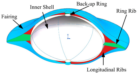
Figure 3.
The schematic of double-layer shell with six longitudinal ribs.

Table 2.
Parameters of double-layer shell.
3.2. Numerical Model
The schematic diagram of a disc-shaped double-layer shell is shown in Figure 4. The finite element mesh size of the structure should be less than 1/6 of the wavelength of the sound wave, which is related to the maximum calculated frequency.
where is Young’s modulus, is thickness, is the density of structure, and is the Poisson ratio. The glider with a disc-shaped double-layer shell that we developed is mainly used for the detection of low-frequency signals of underwater targets. So, the paper mainly focuses on the acoustic responses of the structure at low–medium frequencies within the analysis frequency range of 10–500 Hz. The shell structure adopts a combined grid of quadrilaterals and triangles with a grid cell size of 0.15 m, as shown in Figure 4a.
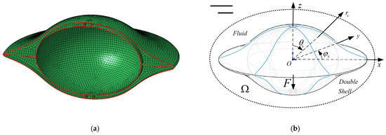
Figure 4.
(a) Grid mesh of model; (b) schemes of shell model and coordinate.
Figure 4b defines the model coordinates. is the coordinate of the field point in the spherical coordinate system centered at the shell origin. is the distance away from the origin, and is the direction of the coordinate. Harmonic excitation with step 1 Hz acts on the bottom of the inner shell perpendicularly, in a direction of 180°. The external fluid domain is water.
4. Results and Discussions
4.1. Dynamic Response of 6-Longitudinal-Ribs
Modal analysis validates the numerical model of the disc-shaped double-layer stiffened shell with stiffeners. Eigenvalue extraction reveals the natural frequencies and fundamental modes, which predominantly cluster in low-to-mid frequency ranges. Table 3 lists the modal frequencies under fluid structure coupling up to 500 Hz.

Table 3.
Coupling modal frequency.
High modal density occurs within 200–400 Hz. Structural resonance emerges when excitation frequency approaches a natural frequency, generating pronounced peaks.
4.2. Vibro-Acoustic Results of Six Longitudinal Ribs
4.2.1. Radiated Acoustic Power
Figure 5 is the acoustic power curve of the disc-shaped double-layer reinforced shell with six longitudinal ribs predicted by using the FEM/AML and DBEM. The results of the two methods have strong agreement.
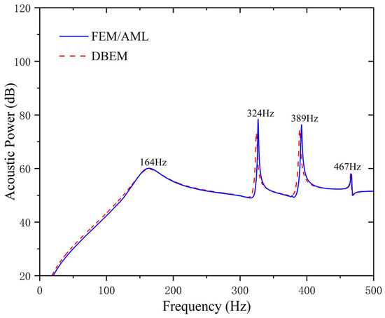
Figure 5.
Acoustic power curve.
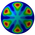
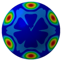
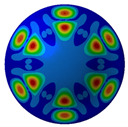
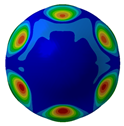
The resonance peak frequency of acoustic power occurs at 164 Hz, 324 Hz, 389 Hz, and 467 Hz. The natural frequency of the numerical model is consistent with the peak frequency observed in the acoustic power curve. The coupling vibration modes at the first four order of resonance frequencies are detailed in Table 4.

Table 4.
Coupling vibration modes at first four resonance frequencies.
4.2.2. Radiated Sound Pressure Level
The SPL at different points in the frequency domain is shown in Figure 6. The monitoring points are located 1 m and 100 m away from the origin on the mid-longitudinal-section below the double-layer shell in 180° and the mid-cross-section in 90° direction, respectively.
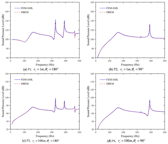
Figure 6.
SPL curves at different points.
The amplitude of the SPL in near-filed of 1 m is higher than that in far-filed of 100 m across 10–500 Hz, consistent with acoustic attenuation characteristics. The amplitude of the SPL is smaller when the pressure monitoring point is the farther away from the excitation sound source.
Resonance peaks at 180° (P1/P3) occur at 164/324/389/467 Hz, peaking at 324 Hz. The maximum amplitude value of the resonant frequencies all occur at 324 Hz. The variation trend results of P1 and P3 have significant differences below 160 Hz. At 90° (P2/P4), dominant peaks appear at 164 Hz and 389 Hz, which means the measurement points in the horizontal direction are not sensitive to the vibration modes of the frequencies at 326 Hz and 467 Hz. The maximum amplitude occurs at 389 Hz.
Both methods have strong agreement in predicting the variation in the SPL response of vibration noise. However, the method of FEM/AML is more sensitive to the vibro-acoustic response caused by the local modes of the shell and has more peaks in the resonance frequency band of the shell. As shown in Figure 6b,d, the FEM/AML can capture the slight response of SPL at a resonance frequency of 326 Hz, where the DBEM has no response. In addition, compared with the DBEM, the FEM/AML has higher computational efficiency and lower requirements on the performance of the computer. So, the results of the research on the vibro-acoustic characteristics of double-layer shells in the following are all obtained based on the method of FEM/AML
4.2.3. Sound Field Directivity and Pressure Spatial Distribution
Figure 7 illustrates acoustic directivity at the first four resonance frequencies (164 Hz, 324 Hz, 389 Hz, and 467 Hz) based on the FEM/AML. It can be seen that SPL symmetry around the midplane reflects the shell’s rotational symmetry.
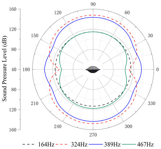
Figure 7.
Acoustic directivity at first four resonance frequencies.
Combined with the contours shown in Table 5 and Figure 8, it can be seen that SPL has full symmetry at 164 Hz. At a frequency of 324 Hz, the amplitude of the sound pressure at the vertical position (90°/270°) is 148.49 dB/148.55 dB; at a frequency of 389 H, the amplitude of the transverse (0°/180°) SPL is 136.33 dB/136.36 dB. The spatial distributions align with the Figure 7 directivity and Figure 6 SPL trends.

Table 5.
SPL amplitude with variation direction at resonance frequencies.
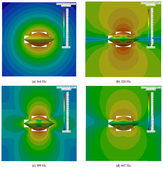
Figure 8.
Sound pressure spatial distribution at first four resonance frequencies.
4.3. Effect of Longitudinal Ribs on Vibro-Acoustic Response
Longitudinal ribs enhance the structural stability and pressure resistance of the disc-shaped double-layer shell, thereby increasing the operational depth of underwater gliders. The number of stiffeners directly affects the natural frequency, modal density, vibration modes, and acoustic radiation efficiency of the glider, so adding stiffeners will alter the external acoustic field characteristics of the underwater glider shell. In the design process of an underwater glider, the natural frequency of the structure is far away from the frequency of its harmonic frequency through optimizing the ribs layout, which helps to avoid strong vibration noise generated by resonance that will improve the acoustic stealth performance of the underwater glider.
4.3.1. Sound Pressure Level Variation
Figure 9 presents the SPL of a disc-shaped double-layer for rib counts from 6 to 10 within 10–500 Hz based on the FEM/AML. Monitoring points at 1 m (180°/90° azimuth) show that the first resonant peak occurs at the following frequencies: 6 ribs: 164 Hz; 8 ribs: 188 Hz; and 10 ribs: 217 Hz. Increased shell stiffness shifts structural coupled-mode frequencies upward, consequently elevating the acoustic resonances.
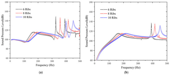
Figure 9.
SPL curves: (a) ; (b) .
In the 180° direction, the maximum SPL amplitude of a double-layer shell with 6 ribs occurs at the second resonant frequency of 324 Hz (148.5 dB), while for 8 and 10 ribs it occurs at 358 Hz (146.2 dB) and 400 Hz (139.1 dB), respectively. Similarly, at the third resonance, 6 ribs yields the highest amplitude, and 10 ribs yields the lowest.
In the 90° direction, the maximum SPL amplitude frequency of a double-layer shell with 6 ribs occurs at a frequency of 389 Hz, that of the 8 ribs occurs at 416 Hz, and that of the 10 ribs occurs at 453 Hz, and the peak amplitudes at the resonant frequency decrease as the rib count rises.
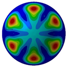
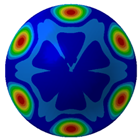
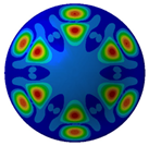
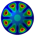
Table 6 displays the vibration modes of a double-layer shell at the first three resonant frequencies. The increase in the number of longitudinal ribs enhances the stiffness of the disc-shaped double-layer shell, promoting the migration of the coupling mode frequency and the resonance frequency of the sound pressure to the high frequency. It can be seen that the displacement variation trend of the modal shapes is consistent with different ribs. Maximum displacement consistently occurs between longitudinal ribs on the fairing. With the increase in frequency, the maximum displacement moves to the edge of the disc. At the third resonant frequency (389 Hz for 6 ribs, 419 Hz for 8 ribs, and 459 Hz for 10 ribs), there are two maximum displacements in the radial direction of the fairing shell, which begin to show a circumferential mode. The maximum displacement position is still between the two stiffened plates, and the number of deformation positions is in a multiple relationship with the number of stiffening plate ribs.

Table 6.
Coupling vibration modes at first three resonance frequencies.
4.3.2. Acoustic Directivity Variation
Figure 10 compares acoustic directivity at the first three resonant frequencies. At the first resonant frequency, the number of ribs has almost no effect on the sound pressure, and the amplitude and directivity are matched perfectly. The acoustic directivity of the first resonant frequency is omni-directional.
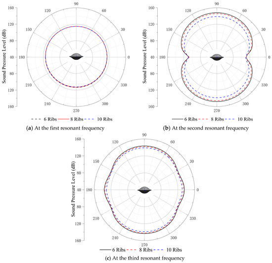
Figure 10.
Acoustic directivity at first three resonance frequencies.
At the second and third resonant frequencies, the disc-shaped double-layer with 6 ribs yields the highest SPL, and the 10 ribs yields the lowest. Sound pressure remains symmetric around the mid-transverse section. The increase in rib numbers and the reduction in the rib spacing will enhance structural stiffness, reducing vibration response post-excitation.
4.3.3. Frequency–Spatial Spectrum of Sound Filed
Figure 11 is the frequency–spatial distribution spectrum of radiated sound pressure. The colors in the contour image can be identified as the amplitude of sound pressure. The highlighted areas represent the occurrence of resonance phenomena, where the amplitude of the radiated sound pressure is the largest.
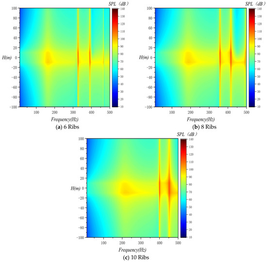
Figure 11.
Frequency–spatial spectrum of sound filed.
As the distance from the shell increases, the radiated sound pressure shows a nonlinear attenuation. H(m) is the vertical distance from the center of gravity position of the double-layer shell. The radiated sound pressure is symmetrically distributed with respect to the position . The influence of the number of stiffening ribs on the resonant frequency is more obvious, and the resonant frequency shifts to the medium and high frequencies with the increase in the number of stiffening ribs. When the monitoring distance exceeds 20 m, the distance has a negligible influence on the amplitude below 100 Hz. This trend agrees with the SPL results in Figure 10a.
5. Conclusions
The paper proposes a disc-shaped double-layer shell structure with reinforcing ribs for underwater gliders. This configuration not only maintains a high lift-to-drag ratio but also enhances reserve buoyancy and optimizes internal space utilization.
Then, the vibro-acoustic coupling characteristics of disc-shaped double-layer shell with six longitudinal ribs were obtained by using the FEM/AML and DBEM. Analyses focused on structural coupled modes, sound pressure level, and acoustic power within 10–500 Hz were analyzed. There are high-density vibration modes within the frequency range of 300–400Hz, which are prone to inducing the occurrence of resonance phenomena. The results for the acoustic directivity and spatial distribution of radiated sound pressure show that the radiated sound pressure is symmetrically distributed with respect to the cross-section of the shell.
Furthermore, the vibro-acoustic responses of double-layers with different stiffener quantities were evaluated. With the increase in the number of reinforcing ribs, the frequency of the structural coupling mode increases, and the resonant frequency in the radiated sound field migrates to the medium-high frequency. It should be pointed out that the model in this paper does not consider the influence of sea surface fluctuation and waves on the radiated sound field, which has certain limitations. The results obtained in this paper provide valuable guidance for acoustically-optimized structural design of disc-shaped underwater gliders.
Author Contributions
Writing, software, resources, and validation—Y.Z.; supervision and editing, T.Y.; conceptualization, Z.S. All authors have read and agreed to the published version of the manuscript.
Funding
This research received no external funding.
Data Availability Statement
The data presented in this study are available upon request from the corresponding author.
Conflicts of Interest
The authors declare no conflicts of interest.
Abbreviations
The following abbreviations are used in this manuscript:
| AML | Automatic Matching Layer |
| DBEM | Direct Boundary Element Method |
| FEM | Finite Element Method |
| SPL | Sound Pressure Level |
References
- Wang, C.; Yuan, M. Research on the Ambient Noise Observation Technology Based on the Underwater Glider. Acoust. Aust. 2021, 49, 485–493. [Google Scholar] [CrossRef]
- Ma, W.; Lou, H.; Li, X.; Wang, P.; Wang, L.; Niu, W.; Yang, M.; Fa, S.; Song, J.; Yang, S. Study on water entry characteristics of an air-droppable underwater glider in hydrostatic water. Phys. Fluids 2025, 37, 017103. [Google Scholar] [CrossRef]
- Dhulekar, A.M.; Sharma, F.; Dixit, U.S. Conceptual Design of a Low Cost Underwater Glider for Educational Purpose. In Advances in Thermo-Fluid Engineering (INCOM 2024); Lecture Notes in Mechanical Engineering Series; Springer: Singapore, 2025; pp. 267–281. [Google Scholar] [CrossRef]
- Nakamura, M.; Noda, J.; Matsumoto, T. Development of Underwater Glider for Virtual Mooring that can be Used in Shallow Water. In Proceedings of the Annual Autumn Meeting 2020, Tokyo, Japan, 16–17 November 2020; The Japan Society of Naval Architects and Ocean Engineers. Volume 31, pp. 427–433. [Google Scholar] [CrossRef]
- Nakamura, M.; Hyodo, T.; Koterayama, W. Development of Disk Type Underwater Glider for Virtual Mooring. J. Jpn. Soc. Nav. Archit. Ocean Eng. 2007, 5, 35–46. [Google Scholar] [CrossRef]
- Lu, L.; Wang, H.; Gu, N.; Peng, Z.; Zhang, W. Distributed Cooperative Guidance Model-Free Control for a Cluster of Disk-type Autonomous Underwater Gliders. IEEE Trans. Autom. Sci. Eng. 2025, 22, 12395–12405. [Google Scholar] [CrossRef]
- Zhou, H.; Wang, T.; Sun, L.; Jin, X. Disc-type underwater glider modeling and analysis for omnidirectional and steering motion characteristics. Int. J. Control Autom. Syst. 2021, 19, 532–547. [Google Scholar] [CrossRef]
- Sun, Z.; Yu, Y.; Li, D.; He, C.; Zhang, Y. Vibroacoustic Response of a Disc-Type Underwater Glider During Its Entry into Water. J. Mar. Sci. Eng. 2025, 13, 544. [Google Scholar] [CrossRef]
- Wang, C.; Yuan, M. Application Study of a New Underwater Glider with Single Vector Hydrophone for Target Direction Finding. IEEE Access 2021, 9, 34156–34164. [Google Scholar] [CrossRef]
- Dash, B.; Mahapatra, T.R.; Mishra, P.; Mishra, D.; Mahmoud, S.R. A Review of Computational Methods for Vibroacoustic Analysis of Advanced Material Structures. Arch. Comput. Methods Eng. 2025, 32, 2187–2211. [Google Scholar] [CrossRef]
- Zhao, K.; Fan, J.; Wang, B.; Tang, W. Analytical and experimental study of the vibro-acoustic behavior of a semi-submerged finite cylindrical shell. J. Sound Vib. 2020, 482, 115466. [Google Scholar] [CrossRef]
- Zhao, K.; Fan, J.; Wang, B.; Li, Y. Modulation of the vibroacoustic behavior of a partially immersed cylindrical shell by regular waves. Appl. Acoust. 2021, 171, 107542. [Google Scholar] [CrossRef]
- Marsick, A.; Sharma, G.S.; Eggler, D.; Maxit, L.; Kessissoglou, N. On the vibro-acoustic response of a cylindrical shell submerged near a free sea surface. J. Sound Vib. 2021, 511, 116359. [Google Scholar] [CrossRef]
- Kha, J. Vibroacoustic Responses of Submerged Elastic Structures in Shallow Water. Ph.D. Thesis, University of Technology Sydney (Australia), Sydney, Australia, 2024. [Google Scholar] [CrossRef]
- Zhuang, Y.; Yang, D.; Li, Q.; Geng, X. Modified vibro-acoustic spectrum characteristics for underwater cylindrical shells with mechanical metastructures. Int. J. Solids Struct. 2025, 310, 113219. [Google Scholar] [CrossRef]
- Zuo, Y.; Yang, D.; Zhuang, Y. Broadband transient vibro-acoustic prediction and control for the underwater vehicle power cabin with metamaterial components. Ocean Eng. 2024, 298, 117121. [Google Scholar] [CrossRef]
- Zou, M.-S.; Yang, Y.-N.; Liu, S.-X. A spherical source distribution method for calculating acoustic radiation of elastic underwater structures. Eng. Anal. Bound. Elem. 2024, 169, 105945. [Google Scholar] [CrossRef]
- Zou, M.-S.; Liu, S.-X.; Yang, Y.-N. On near-and far-field acoustic radiation characteristics of ships in finite-depth water environment. Appl. Acoust. 2021, 172, 107644. [Google Scholar] [CrossRef]
- Zou, M.-S.; Liu, S.-X.; Jiang, L.-W.; Huang, H. A mixed analytical-numerical method for the acoustic radiation of a spherical double shell in the ocean-acoustic environment. Ocean Eng. 2020, 199, 107040. [Google Scholar] [CrossRef]
- Zou, M.-S.; Wu, Y.-S.; Liu, S.-X. A three-dimensional sono-elastic method of ships in finite depth water with experimental validation. Ocean Eng. 2018, 164, 238–247. [Google Scholar] [CrossRef]
- Jiang, L.-W.; Zou, M.-S.; Zhou, Y.; Guo, W. Calculation method with experimental validation of underwater acoustic radiation of composite laminate structures. Appl. Acoust. 2025, 238, 110798. [Google Scholar] [CrossRef]
- Sun, J.; Wang, X.; Tu, S.; Yu, M.; Gu, X.; Qi, W. A Hybrid Analytic-Numerical Approach for Vibro-Acoustic Analysis of a Combined Shell with interior Substructures. J. Vib. Eng. Technol. 2025, 13, 112. [Google Scholar] [CrossRef]
- Tang, Y.; Zhao, Z.; Qin, Y.; Pang, F.; Du, Y.; Gao, C.; Li, H. Experimental and numerical investigation on vibro-acoustic performance of a submerged stiffened cylindrical shell under multiple excitations. Thin-Walled Struct. 2024, 197, 111569. [Google Scholar] [CrossRef]
- Li, H.; Xu, J.; Pang, F.; Gao, C.; Zheng, J. A unified Jacobi-Ritz-spectral BEM for vibro-acoustic behavior of spherical shell. Comput. Math. Appl. 2024, 176, 415–431. [Google Scholar] [CrossRef]
- Gao, C.; Xu, J.; Pang, F.; Li, H.; Wang, K. Modeling and experiments on the vibro-acoustic analysis of ring stiffened cylindrical shells with internal bulkheads: A comparative study. Eng. Anal. Bound. Elem. 2024, 162, 239–257. [Google Scholar] [CrossRef]
- Dong, W.; Huang, Z.; Wang, T.; Chen, M. Low-frequency vibration reduction of an underwater metamaterial plate excited by a turbulent boundary layer. J. Fluids Struct. 2024, 126, 104103. [Google Scholar] [CrossRef]
- Zhang, X.; Li, H.; Xiong, H.; Sun, S.; Ling, Z.; Shen, G.; Zhao, X.; Chen, B.; Meng, G. Design and experimental validation of a broadband multi-modal coupled capsule-shaped transducer for underwater acoustics. Sens. Actuators A Phys. 2024, 373, 115393. [Google Scholar] [CrossRef]
- Zhao, T.; Ye, T.; Chen, Y.; Jin, G.; Liu, Z. Vibroacoustic analysis of submerged fluid-filled cylindrical shell. Int. J. Mech. Sci. 2024, 275, 109330. [Google Scholar] [CrossRef]
- Masoodi, A.R.; Ghandehari, M.A.; Tornabene, F.; Dimitri, R. Natural Frequency Response of FG-CNT Coupled Curved Beams in Thermal Conditions. Appl. Sci. 2024, 14, 687. [Google Scholar] [CrossRef]
- Ghandehari, M.A.; Masoodi, A.R.; Panda, S.K. Thermal Frequency Analysis of Double CNT-Reinforced Polymeric Straight Beam. J. Vib. Eng. Technol. 2024, 12, 649–665. [Google Scholar] [CrossRef]
Disclaimer/Publisher’s Note: The statements, opinions and data contained in all publications are solely those of the individual author(s) and contributor(s) and not of MDPI and/or the editor(s). MDPI and/or the editor(s) disclaim responsibility for any injury to people or property resulting from any ideas, methods, instructions or products referred to in the content. |
© 2025 by the authors. Licensee MDPI, Basel, Switzerland. This article is an open access article distributed under the terms and conditions of the Creative Commons Attribution (CC BY) license (https://creativecommons.org/licenses/by/4.0/).
