Article

Adaptive Path Tracking Control of X-Rudder AUV Under Roll Constraints

1
Naval Architecture and Shipping College, Guangdong Ocean University, Zhanjiang 524088, China
2
Guangdong Provincial Key Laboratory of Intelligent Equipment for South China Sea Marine Ranching, Guangdong Ocean University, Zhanjiang 524088, China
3
College of Shipbuilding Engineering, Harbin Engineering University, Harbin 150001, China
4
Hangzhou Applied Acoustics Research Institute, Hangzhou 310000, China
*
Author to whom correspondence should be addressed.
J. Mar. Sci. Eng. 2025, 13(9), 1778; https://doi.org/10.3390/jmse13091778
Submission received: 3 August 2025 / Revised: 10 September 2025 / Accepted: 11 September 2025 / Published: 15 September 2025
(This article belongs to the Section Ocean Engineering)

Abstract

This paper addresses the spatial path tracking problem of the X-rudder autonomous underwater vehicle (AUV) under random sea current disturbances. An adaptive line-of-sight guidance-linear quadratic regulator (ALOS-LQR) control strategy with roll constraints is proposed to enhance the tracking control accuracy and stability of the X-rudder AUV in such environments. First, to mitigate the roll-instability-induced depth and heading coupling deviations caused by unknown environmental disturbances, a roll-constrained linear quadratic regulator (LQR) heading-pitch control strategy is designed. Second, to handle random disturbances and model uncertainties, a nonlinear extended state observer (ESO) is employed to estimate dynamic disturbances. At the kinematic level, an adaptive line-of-sight guidance method (ALOS) is utilized to transform the path tracking problem into a heading and pitch tracking problem, while compensating in real time for kinematic deviations caused by time-varying sea currents. Finally, the effectiveness of the proposed control scheme is validated through simulation experiments and lake trials. The results confirm the effectiveness of the proposed method. Specifically, the roll-constrained ESO-LQR reduces lateral and longitudinal errors by 77.73% and 80.61%, respectively, compared to the roll-constrained LQR. ALOS navigation reduced lateral and longitudinal errors by 85.89% and 94.87%, respectively, compared to LOS control, while exhibiting faster convergence than ILOS. In physical experiences, roll control reduced roll angle by 50.52% and depth error by 33.3%. Results demonstrate that the proposed control strategy significantly improves the control accuracy and interference resistance of the X-rudder AUV, exhibiting excellent accuracy and stability.

1. Introduction

Autonomous underwater vehicles (AUVs) are widely used and important platforms in the marine domain, integrating multiple key capabilities from robotics, including path planning [1,2], navigation and positioning [3], motion control [4], and so on. They have become indispensable platforms for ocean exploration and development. Due to their unique and outstanding maneuverability, AUVs have broad application prospects in both civilian and military fields, including seabed topography mapping, environmental monitoring, search and rescue of crashed aircraft and sunken ships, pipeline inspection, and other areas [5]. As AUVs are tasked with increasingly diverse and complex missions, traditional AUVs are no longer sufficient to meet mission requirements. In order to complete complex underwater tasks more efficiently, the X-rudder AUV has become one of the current research hotspots due to its superior maneuverability and mobility [6,7].
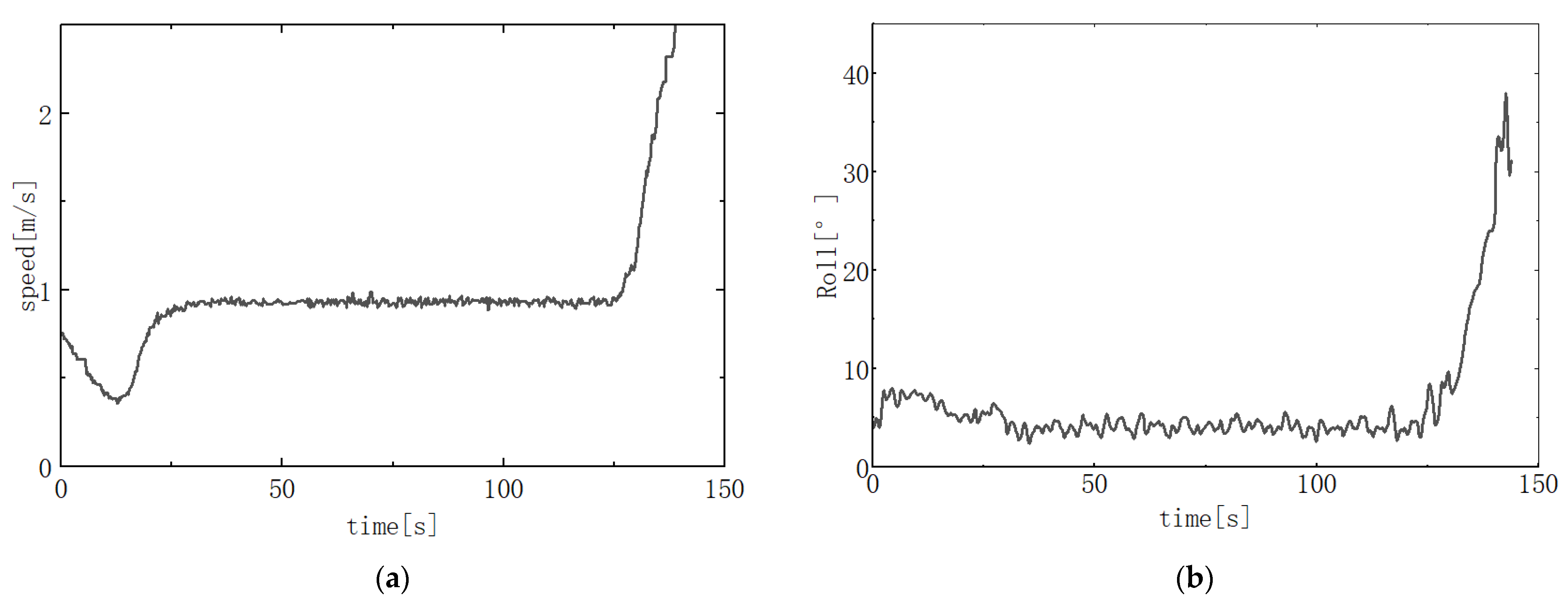
The X-rudder AUV experiences roll deviation issues due to the influence of X-rudder control forces, propeller thrust torque, and time-varying ocean current disturbances. The instability of roll motion indirectly affects the AUV’s heading and pitch control through coupling effects. However, due to their compact size, small AUVs have a shorter distance between their center of gravity and center of buoyancy, resulting in insufficient self-recovery torque to counteract roll effects [8,9]. Under coupled effects, roll instability may further induce heading and depth control deviations. Liu [10] discussed AUV attitude control, explaining that roll instability impacts mission attitude accuracy. Huy Ngoc Tran [11] addressed the influence of model uncertainty and propulsion torque coupling on depth/heading performance in depth control, emphasizing that roll attitude coupling leads to depth deviations. Ahsan Tanveer [12] explicitly analyzes cross-couplings between depth and heading with other degrees of freedom, noting that uncompensated coupling significantly degrades closed-loop performance. Our research group conducted straight-line navigation experiments using an X-rudder underwater vehicle prototype. As shown in Figure 1, the X-rudder AUV deviated from its intended trajectory due to roll-yaw coupling effects. As illustrated in Figure 2, severe roll deviation caused by the thrust torque of the roll thrusters indirectly led to overloading and safety incidents. Therefore, controlling roll motion during navigation is imperative. In addition, environmental factors such as sea conditions and sea areas are subject to change, and the direction and magnitude of these changes are highly uncertain. These uncertainties and other influences aggravate roll instability, posing a significant challenge to AUV path tracking control. In existing roll control schemes, Ebrahimi [9] uses a coupled fin to control roll, but this method has special requirements for the structure of the AUV. Since the rudder surfaces of the X rudder can generate torque in different directions, control torque can be generated in the roll direction by inputting appropriate rudder angles separately and controlling the rudder angles differentially, thereby suppressing the roll motion of the AUV. Huang [13] verified the feasibility of X-rudder control of roll in lake trials of straight-line navigation experiments. Although Huang verified the unique advantages of the X rudder in AUV roll control, there are few studies in the existing literature on reducing roll coupling and improving path tracking control performance by constraining the roll angle with the X rudder.
Path tracking control can generally be divided into kinematic control and dynamic control. Currently, researchers have proposed a number of methods for dynamic control of AUVs under uncertain interference [14], such as Proportional-Integral-Differential (PID) control, Linear Quadratic Optimal (LQR) control, Backstepping control [15], Model Predictive control (MPC) [16], Active Disturbance Rejection control (ADRC) [17], etc. Among them, LQR has the advantages of convenient design, simple and easy-to-adjust parameters [4], etc. However, in engineering practice, AUVs are subject to unknown ocean currents during navigation, as well as model uncertainties and other issues that limit their control accuracy. To address this issue, Yuan [18] proposed an adaptive control linear quadratic optimal (L1AC-LQR) control algorithm, combining L1AC to compensate for the controller and optimize the heading and depth control performance of the X-rudder AUV; Yu [19] designed a double-loop depth tracking scheme using a linear quadratic regulator, incorporating an Extended State Observer (ESO) into the dynamic controller to observe disturbance terms, significantly improving the tracking accuracy of the AUV under model uncertainty and actuator fluctuations. However, most studies have not sufficiently explored the effects of roll motion coupling.
In kinematic control, line-of-sight (LOS) guidance is the most common method. This method generates the required control variables for heading and pitch by tracking error and lead distance, and has been widely applied in trajectory tracking or path following tasks [20,21]. However, AUVs using traditional line-of-sight (LOS) tracking methods are unable to effectively counteract the heading angle effects caused by ocean currents, leading to a decrease in tracking accuracy. To address this issue, Fossen [22] proposed an Integral LOS (ILOS) motion guidance method based on the traditional LOS algorithm to compensate for the crab angle β problem, eliminating the impact of constant external disturbances on straight-line path tracking and improving the robustness and stability of the algorithm. However, ILOS compensates for lateral drift through a saturated inverse tangent function, resulting in relatively slow error convergence. In addition, other improved LOS applications have been applied to AUVs, such as Huang [23] proposed a guidance law based on a hyperbolic tangent line of sight (HLOS) for X-rudder AUVs. This law considers three-dimensional tracking errors and coordinates the control of heading, pitch, and roll. This guidance method can avoid unreasonable guidance angles, thereby avoiding aggressive excitation caused by large cross-tracking errors, which can make roll maneuver angles dangerous. Fossen [24] proposed a nonlinear adaptive guidance law called Adaptive-LOS (ALOS), which can estimate the crab angle during navigation by integrating errors and quickly compensating for the guidance law. Yu [19] used ALOS to compensate for kinematic disturbances caused by unknown angles of attack in kinematic outer-loop guidance and verified through experiments that the tracking method used could effectively overcome complex disturbances.
Although the above studies have performed a great deal of work on kinematic control and dynamic control in terms of time-varying sea current interference and model uncertainty, there has been little research on X-rudder AUV spatial path tracking under roll coupling constraints. To address this issue, this paper proposes an adaptive line-of-sight guidance-linear quadratic regulator (ALOS-LQR) strategy with roll constraints. The main contributions of this paper are as follows:
1.
A roll-constrained LQR controller is developed to suppress the heading and depth tracking errors caused by roll coupling.
2.
An extended state observer (ESO) is integrated to enhance robustness against random disturbances and model uncertainties.
3.
An adaptive line-of-sight (ALOS) guidance scheme is introduced to compensate for time-varying ocean current interference, improving the real-time performance of path tracking.
The remaining content of this paper is as follows: First, Section 2 introduces the mathematical model of the X-rudder AUV. By analyzing the rudder force model of the X-rudder AUV and introducing the wave interference dynamic model, the mathematical model of the X-rudder AUV is derived. Section 3 introduces the ALOS-LQR control design. Section 4 discusses and compares the effects of roll instability on heading and depth tracking, as well as path tracking performance under various disturbances using different guidance algorithms, through simulation experiments. Section 5 conducts physical experiments on variable depth and variable heading tracking control of the X-rudder AUV prototype under roll constraints to validate the effectiveness of the proposed method. Section 6 summarizes the entire paper.

2. X-Rudder AUV Mathematical Model

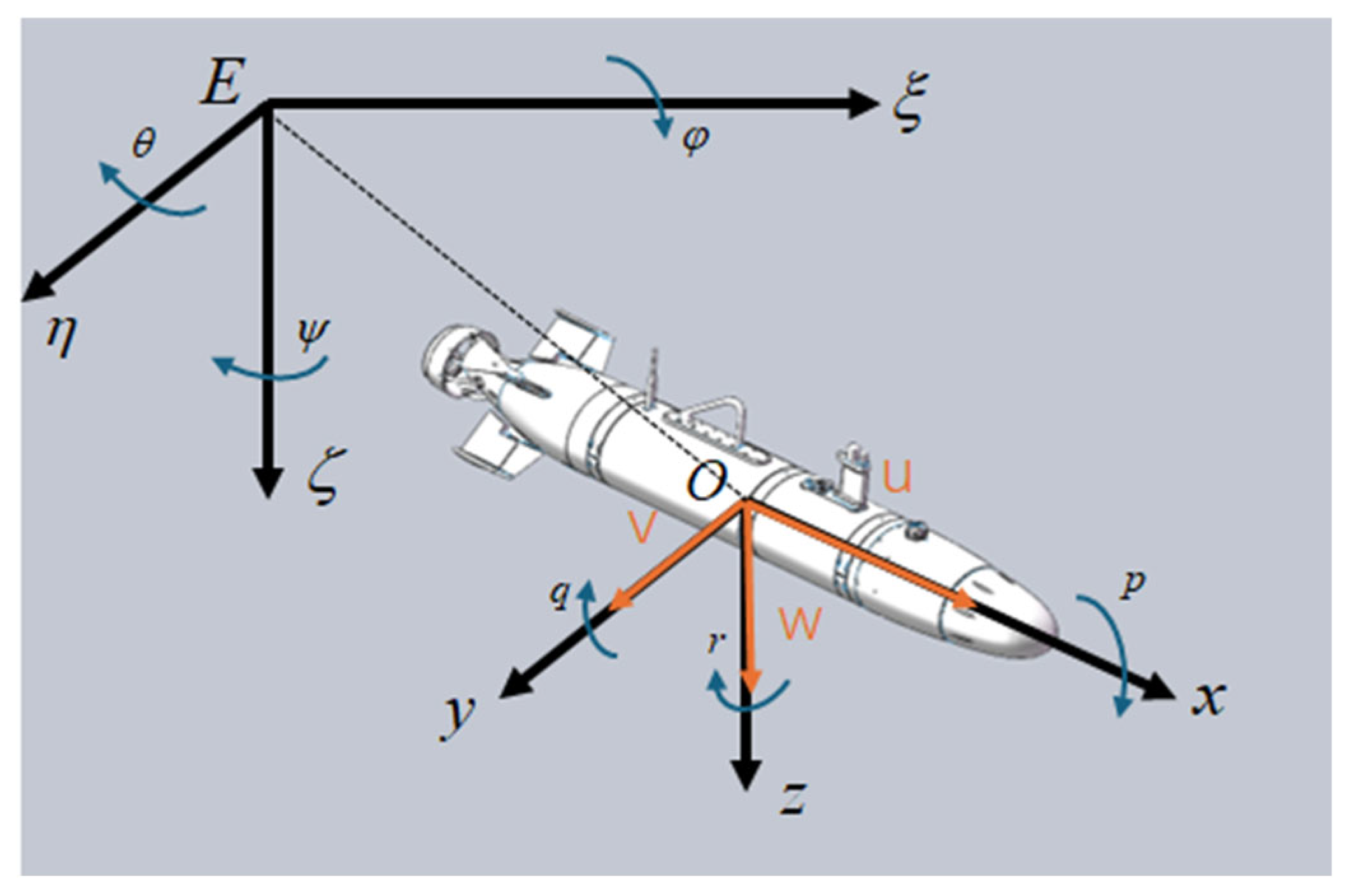
In order to study the laws of AUV maneuvering motion and determine the position and attitude of the moving AUV, this paper adopts the coordinate systems recommended by the International Tank Testing Conference (ITTC) and the Society of Naval Architects and Marine Engineers (SNAME), establishing the fixed coordinate system E ξ η ζ   and the moving coordinate system O x y z as shown in Figure 3. Among them, the forward direction, starboard direction, and downward direction of the AUV correspond to the x-axis, y-axis, and z-axis, respectively.
The center of gravity on the z-axis is denoted as z g ; The relative velocity at the center of gravity of the AUV is V, and the projection of V on the O x y z coordinate system is u, v, w; The angular velocities of the AUV around the x-axis, y-axis, and z-axis are p, q, and r, respectively. The projections of the resultant force acting on the AUV on the O x y z plane are X, Y, and Z; the torques are K, M, and N. In addition, the roll angle φ , pitch angle θ , and yaw angle ψ of the AUV.

2.1. Kinematics and Dynamics Model of X-Rudder AUV

The X rudder is arranged symmetrically at a 45° angle relative to the main body. Its spatial force system decomposition exhibits multi-degree-of-freedom coupling characteristics, enabling the generation of roll torque, yaw torque, and pitch torque by outputting different rudder angles. The four rudders are numbered counterclockwise starting from the lower left corner as Rudder Blades 1, 2, 3 and 4. The counterclockwise direction of the rudders is defined as the positive direction of the force, as shown in Figure 4.
In order to better describe the dynamic equations of the X-rudder AUV [25,26], the following assumptions are made regarding the forces acting on the X-rudder.
Assumption 1.
The coupling effects of the longitudinal force component, lateral force component, and vertical force component generated by the X rudder on the AUV dynamics can be ignored.
Assumption 2.
The control input of the X rudder is bounded   δ * < 30 , i.e., the rudder force provided is limited. At the same time, the rudder angle control response time is not affected by environmental interference, and the response speed is constant.
The torque of the rudder in the roll, pitch, and yaw directions is:
τ K τ M τ N = k 1 V 2 l k 1 2 2 k 1 V 2 l m 1 2 2 k 1 V 2 l n 1 k 2 V 2 l k 2 2 2 k 2 V 2 l m 2 2 2 k 2 V 2 l n 2 k 3 V 2 l k 3 2 2 k 3 V 2 l m 3 2 2 k 3 V 2 l n 3 k 4 V 2 l k 4 2 2 k 4 V 2 l m 4 2 2 k 4 V 2 l n 4 δ 1 δ 2 δ 3 δ 4
In the equation, τ * represents the rudder torque in the roll, pitch, and yaw directions; k * represents the rudder torque coefficient;   l k i ,   l m i ,   l n i   i = 1 ,   2 ,   3 ,   4 represents the roll momentum arm, pitch momentum arm, and yaw momentum arm of rudders 1, 2, 3, and 4, respectively; δ * represents the rudder angle.
According to Fossen [24]. The description of an AUV using Newton-Euler equations and Lagrange formulas is shown in (2).
η ˙ = J θ ( η ) v r M v r + C ( v r ) v r + D ( v r ) v r + g ( η ) = τ p + τ r
M is the inertia matrix of the rigid body mass and additional mass; η is the position and attitude vector of the AUV; v r is the relative sea current velocity and angular velocity vector of the AUV. C is the rigid body mass and additional mass Coriolis centrifugal force matrix; D is the fluid damping matrix; g η is the restoring force vector generated by gravity and buoyancy; τ p is the AUV’s thrust vector; τ r is the AUV’s rudder force vector. Expand the six-degree-of-freedom model of the X-rudder AUV as shown in Equation (3).
In Equation (3): m represents the mass of the AUV; W represents the gravitational force of the AUV; B represents the buoyant force of the AUV; x g ,   y g ,   z g and x b ,   y b ,   z b denote the center of gravity and center of buoyancy of the AUV, respectively; X * ,   Y * ,   Z * ,   K * ,   M * ,   N * represent the first-order hydrodynamic coefficients of the AUV; X * * ,   Y * * ,   Z * * ,   K * * ,   M * * ,   N * * are the coupled hydrodynamic coefficients of the AUV, with specific parameters as shown in Table 1; σ * represents unknown random disturbances such as ocean currents.
m ( u ˙ v r r + w r q ) = X u | u | u r | u r | + X u ˙ u ˙ + X w q w r q + X q q q q + X v r v r r + X r r r r ( W B ) sin θ + X T + σ X m ( v ˙ w r q + u r r ) = ( W B ) sin ϕ cos θ + Y v | v | v r | v r | + Y r | r | r | r | + Y v ˙ v ˙ + Y r ˙ r ˙ + Y u r u r r + Y w q w r q + Y p q p q + Y u v u r v r + σ Y m ( w ˙ u r q + v r p ) = ( W B ) cos ϕ sin θ + Z w | w | W r | w r | + Z q | q | q | q | + Z w ˙ w ˙ + Z q ˙ q ˙ + Z u q u r q + Z v p v r p + Z r p r p + Z u w u r w r + σ Z I x x p ˙ + ( I z z I y y ) q r = ( y g W y b B ) cos ϕ cos θ ( z g W z b B ) sin ϕ cos θ + K p | p | p | p | + K p ˙ p ˙ + τ K + K T + σ K I y y q ˙ + ( I x x I y y ) r p = M w | w | w r | w r | + M q | q | q | q | + M w ˙ w ˙ + M q ˙ q ˙ + M u q u r q + M v p v r p + M r p r p + M u w u r w r + τ M + σ M I z z r ˙ + ( I x x I y y ) p q = ( x g W x b B ) sin ϕ cos θ ( y g W y b B ) sin θ + N v | v | v r | v r | + N r | r | r | r | + N v ˙ v ˙ + N r ˙ r ˙ + N u r u r r +                                      N w p w r p + N p q p q + N u v u r v r + τ N + σ N x ˙ = u r cos ψ cos θ + v r ( cos ψ sin θ sin φ sin ψ cos φ ) + w r ( cos ψ sin θ sin φ + sin ψ sin φ ) y ˙ = u r sin ψ cos θ + v r ( sin ψ sin θ sin φ + cos ψ cos φ ) + w r ( sin ψ sin θ cos φ cos ψ sin φ ) z ˙ = u r sin θ + v r cos θ sin φ + w r cos θ sin φ φ ˙ = p + q tan θ sin φ + r tan θ cos φ θ ˙ = q cos φ r sin φ ψ ˙ = ( q sin φ + r cos φ ) / cos φ

2.2. Ocean Current Interference Model

The motion characteristics of AUVs are affected by time-varying ocean currents. In order to obtain a time-varying ocean current interference model, this paper refers to the vector synthesis method of Long [27] and Chen [28], converting the absolute velocity of the AUV into a relative velocity that takes into account the effect of ocean current velocity, thereby simulating time-varying ocean current interference.
Referring to Fossen’s [21] description of time-varying ocean current models, assuming that the ocean current velocity in the fixed coordinate system is V C , the changes in the ocean current model are shown in Equation (4).
V ˙ c + μ V c = ω
In the equation, μ is a control coefficient greater than or equal to 0; ω is Gaussian white noise. The angle between the projection of the velocity on the horizontal plane E ξ η and the normal of the horizontal plane is the flow direction angle ψ C ; the angle between the projection of the velocity on the horizontal plane E ξ ζ and the normal of the vertical plane is the flow direction angle θ C . The axial component velocities u c , v c , w c of the ocean current in the fixed coordinate system are as follows:
u c = V C cos ( θ c ) cos ( ψ c ) v c = V C cos ( θ c ) sin ( ψ c ) w c = V C sin ( θ c )
The speed of an AUV affected by ocean currents can be expressed as follows:
u r = u ( u c cos ( ψ ) cos ( θ ) + v c sin ( ψ ) cos ( θ ) w c sin ( θ ) ) v r = v ( u c sin ( ψ ) + v c cos ( ψ ) ) w r = w ( u c cos ( ψ ) sin ( θ ) + v c sin ( ψ ) sin ( θ ) + w c cos ( θ ) )
In order to satisfy the convergence conditions for control, the following assumptions are proposed [21].
Assumption 3.
The ocean current velocity  V c  is bounded, satisfying  V c V c ¯ ,   V c ˙ V c ˙ ¯ .   V c ¯  and  V c ˙ ¯  are constants.
Assumption 4.
The direction angles   θ c  and  ψ c  of the ocean current change slowly and are randomly sampled within the range [−π, π].

3. Controller Design

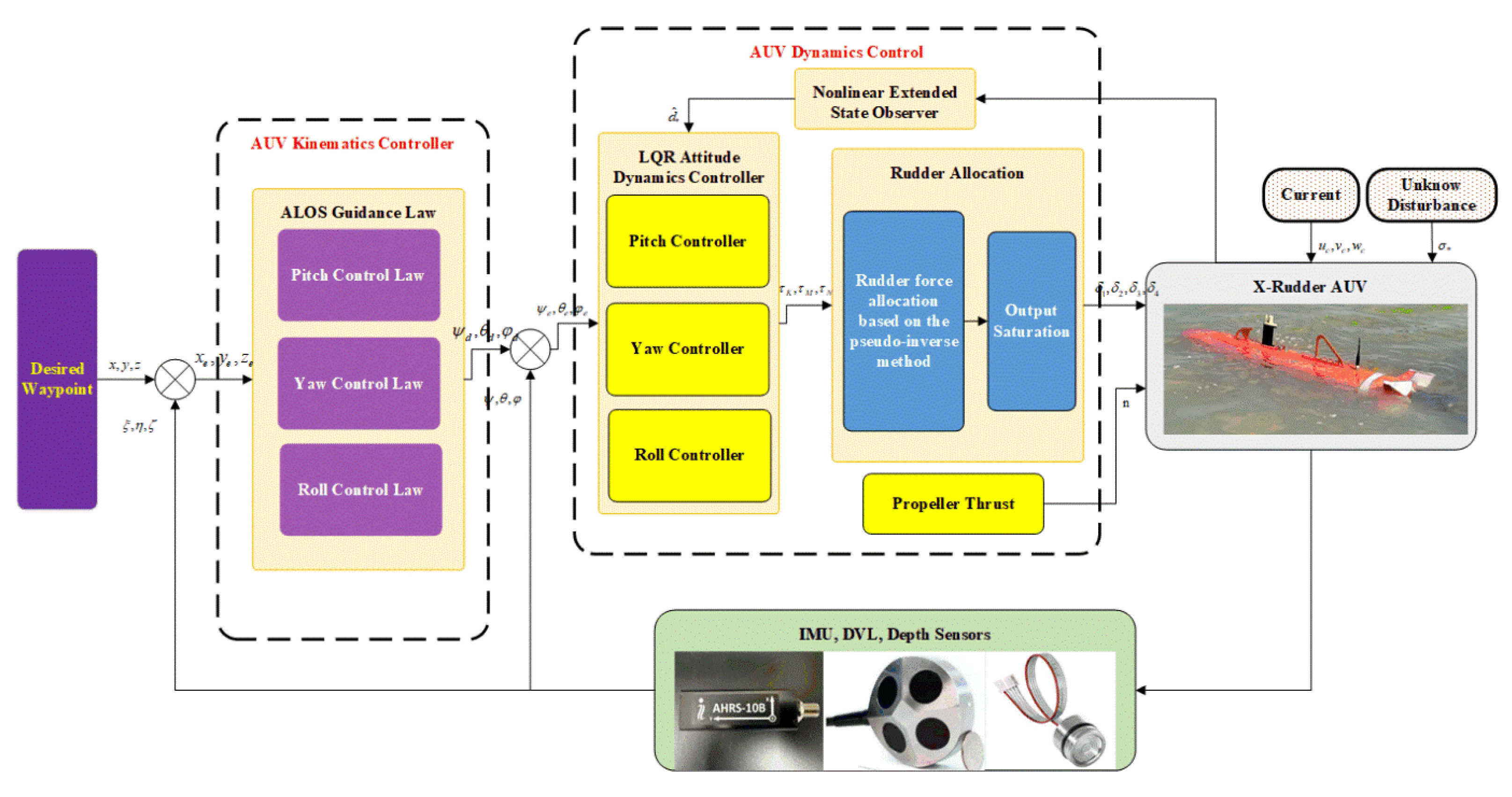
In this chapter, we will provide a detailed introduction to the controller design proposed in this paper. The control block diagram is shown in Figure 5. First, the displacement errors x e ,   y e ,   z e are obtained by subtracting the sensor data ξ ,   η ,   ζ   from the target distances x ,   y ,   z . The kinematic ALOS controller converts displacement errors x e ,   y e ,   z e into desired attitude information ψ d ,   θ d ,   φ d . Next, the desired attitude information ψ d ,   θ d ,   φ d is subtracted from the sensor’s attitude data ψ ,   θ ,   φ to obtain the attitude error ψ e ,   θ e ,   φ e . Then, the attitude errors ψ e ,   θ e ,   φ e are input into the LQR dynamic controller and the nonlinear extended state observer compensation d ^ * to obtain the control rates τ K ,   τ M ,   τ N . The control rates are then converted into yaw angle outputs δ 1 ,   δ 2 ,   δ 3 ,   δ 4 using the pseudo-inverse control allocation method. Finally, the dynamic controller inputs the steering angle command and thruster speed n obtained into the AUV model. In addition, the AUV model is also affected by time-varying sea current disturbances u c ,   v c ,   w c and other unknown disturbances σ * .

3.1. Adaptive Line-of-Sight Guidance (ALOS)

To address the impact of ocean current interference on AUV path tracking, ALOS is used to estimate crab angle and angle of attack online, dynamically adjusting the guidance law to counteract ocean current interference and compensate for lateral and longitudinal deviations caused by disturbances, thereby significantly improving path tracking accuracy. The pitch and heading guidance diagram of the AUV is shown in Figure 6, where V 1 and V 2 are the projections of the resultant velocity V in the   O x y   and O x z   coordinate systems, respectively.
The tangent direction of the tracking point x i n ,   y i n ,   z i n   of the target and the tracking point x i + 1 n ,   y i + 1 n ,   z i + 1 n of the next target is used as the x-axis of the SF coordinate system, and the normal direction of this line is used to construct the SF coordinate system. The tracking error is x e S F ,   y e S F ,   z e S F as Equation (7):
x e S F y e S F z e S F = R y T R z T x n y n z n x i n y i n z i n
Among them, x n ,   y n ,   z n is the position information of the AUV in the terrestrial coordinate system; R y ,   R z represent the transformation matrices of the coordinate system, as shown in Equation (8).
R y = cos ( π v ) 0 sin ( π v ) 0 1 0 sin ( π v ) 0 cos ( π v ) S O ( 3 )    π v = a t a n 2 z i + 1 n z i n x i + 1 n x i n 2 + y i + 1 n y i n 2 R z = cos ( π h ) sin ( π h ) 0 sin ( π h ) cos ( π h ) 0 0 0 1 S O ( 3 )    π h = a t a n 2 y i + 1 n y i n x i + 1 n x i n
where π h is the angle between the terrestrial coordinate system and the tangential coordinate system rotated around the z-axis; π v is the angle between the terrestrial coordinate system and the tangential coordinate system rotated around the y-axis. The heading guidance law is given by Equation (9).
ψ d = π h β ^ c tan 1 y e S F Δ 1
β ^ ˙ c = γ 1 Δ 1 Δ 1 2 + y e S F 2   y e S F
In the equation, β ^ c represents the adaptive crab angle; Δ 1 represents the forward range; γ 1 represents the gain coefficient, and the pitch guidance law is given by Equation (11).
θ d = π v α ^ c tan 1 z e S F Δ 2
α ^ ˙ c = γ 2 Δ 2 Δ 2 2 + z e S F 2   z e S F
In the equation, α ^ c represents the adaptive angle of attack; Δ 2 represents the forward viewing distance; γ 2 represents the gain coefficient. When γ 1 ,   γ 2 > 0 , β ^ c and α ^ c are updated by Equations (10) and (12), and ultimately converge to the true crab angle or angle of attack [19,24].

3.2. Nonlinear Extended State Observer

Ocean currents have time-varying nonlinear characteristics and are difficult to obtain directly through sensors. Furthermore, the uncertainty of AUV models is difficult to describe accurately in control design. To improve the robustness of pitch angle and heading angle tracking control, it is necessary to design a nonlinear disturbance observer to fit the disturbance in real time and compensate for the controller.
Set x 1 = ψ ,   x 2 = r ,   x 3 = θ ,   x 4 = q ,   x 5 = φ ,   x 6 = p to reconstruct the system into a model with explicit coupling interference terms as shown in Equation (13).
x ˙ 1 = x 2 x ˙ 2 = f r + b 1 τ N + d N x ˙ 3 = x 4 x ˙ 4 = f q + b 2 τ M + d M x ˙ 5 = x 6 x ˙ 6 = f p + b 3 τ K + d K
In the equation, b 1 ,   b 2 ,   b 3 represent the corresponding control torque gains, respectively, and f r ,   f q ,   f p are expanded as shown in the equation.
f r = ( x g W x b B ) sin ϕ cos θ ( y g W y b B ) sin θ + N v | v | v r | v r | + N r | r | r | r | + N v ˙ v ˙ + N r ˙ r ˙ + N u r u r r + N w p w r p + N p q p q + N u v u r v r ( I x x I y y ) p q I z z f q = M w | w | w r | w r | + M q | q | q | q | + M w ˙ w ˙ + M q ˙ q ˙ + M u q u r q + M v p v r p + M r p r p + M u w u r w r ( I x x I y y ) r p I y y f p = ( y g W y b B ) cos ϕ cos θ ( z g W z b B ) sin ϕ cos θ + K p | p | p | p | + K p ˙ p ˙ + K T ( I z z I y y ) q r I x x
Linear ESO employs fixed gain estimation to account for unknown system parameters, resulting in poor interference resistance and slow convergence. To address this, an AUV nonlinear ESO controller is designed based on Han’s description [29] of nonlinear ESO (as shown in the Equation (15)).
x ^ ˙ 1 = x ^ 2 k 1 x 1 x ^ 1 x ^ ˙ 2 = f r + b 1 τ N + d ^ N k 2 f a l ( x 1 x ^ 1 , α 1 , δ ) d ^ ˙ N = k 3 f a l ( x 1 x ^ 1 , α 2 , δ ) x ^ ˙ 3 = x ^ 4 k 4 x 4 x ^ 4 x ^ ˙ 4 = f p + b 2 τ M + d ^ M k 5 f a l ( x 4 x ^ 4 , α 3 , δ ) d ^ ˙ M = k 6 f a l ( x 4 x ^ 4 , α 4 , δ ) x ^ ˙ 5 = x ^ 6 k 7 x 5 x ^ 5 x ^ ˙ 6 = f q + b 3 τ M + d ^ K k 8 f a l ( x 5 x ^ 5 , α 5 , δ ) d ^ ˙ K = k 9 f a l ( x 5 x ^ 5 , α 6 , δ )
In the equation, x ^ * represents the estimated state variable, and k * is the gain of the observer, where k * < 0 . The specific expression of f a l · is:
f a l ( e , α , δ ) = | e | α sign ( e ) , | e | > δ e δ 1 α , | e | δ

3.3. LQR Controller and Rudder Force Distribution

This section introduces the design of the LQR controller for the pitch, yaw, and roll of the AUV. For the pitch motion state variables of the AUV, q ,   θ , the state equation for the pitch motion is:
q ˙ θ ˙ = M q M θ 1 0 q θ + M δ M 0 δ M + d M 0
The state variables of yaw motion are v ,   r ,   ψ , and the state equation of yaw motion is:
v ˙ r ˙ ψ ˙ = Y v Y r 0 N v N r 0 0 1 0 v r ψ + Y δ N N δ N 0 δ N + 0 d N 0
The state variable for roll motion is p ,   φ , and the state equation for roll motion is:
p ˙ φ ˙ = K q q 0 1 0 p φ + 1 0 δ R + d K 0
In Equations (17)–(19) δ M ,   δ N ,   δ R denote the virtual elevator, rudder, and differential rudder generated by the X-rudder transformation, respectively. The transformation relationship between the X-rudder and the virtual control surfaces is given in Equation (20).
δ M = 2 2 δ 1 δ 2 δ 3 + δ 4 δ N = 2 2 δ 1 δ 2 + δ 3 + δ 4 δ R = 1 2 δ 1 δ 2 δ 3 δ 4
For a system x t = A x t + b u t , the state variables are fed back into the system through the gain matrix K. The control law of the LQR controller is u t = K x t . Given appropriate Q and R matrices, the cost function J is minimized to achieve the best control performance of the controller.
J = 0 [ x T ( t ) Q x ( t ) + u T ( t ) R u ( t ) ] d t
Then, from Equations (15) and (17)–(19), the roll, pitch, and yaw control laws can be obtained as shown in Equation (22):
τ K = k p p + k φ ( φ φ d ) + d ^ K τ M = k q q + k θ θ θ d + d ^ M τ N = k v v + k r r + k ψ ( ψ ψ d ) + d ^ N
In the equation, k * represents the parameters of the LQR controller. The pitch, yaw, and roll torques obtained from the above are distributed to the four rudder angles using a pseudo-inverse control distribution method. The distribution model is as follows:
δ * = B T ( B B T ) 1 τ         ( R ( B ) = R ( B , τ ) ) δ * = ( B B T ) 1 B T τ         ( R ( B ) R ( B , τ ) )
In the equation, δ * is the rudder angle vector, expressed as δ * = δ 1 ,   δ 2 ,   δ 3 ,   δ 4 T ,   δ < 30 , representing the rudder angles of rudders. R B denotes the rank of matrix B. When R B = R B , τ , the control allocation equation admits a consistent solution, which can be obtained through the pseudo-inverse of B. When R B R B , τ , the desired control moment τ does not lie in the column space of B, indicating that it exceeds the achievable range of the rudders. The allocated rudder commands are then passed through a saturation process to ensure that the physical constraints are satisfied. In the equation, matrix B is:
B = k 1 V 2 l k 1 k 1 V 2 l m 1 k 1 V 2 l n 1 k 2 V 2 l k 2 k 2 V 2 l m 2 k 2 V 2 l n 2 k 3 V 2 l k 3 k 3 V 2 l m 3 k 3 V 2 l n 3 k 4 V 2 l k 4 k 4 V 2 l m 4 k 4 V 2 l n 4
In the equation, k * are the rudder force coefficients for rudders.

3.4. Stability Analysis

The proof is presented below to establish the stability of both the kinematic controller and the dynamic controller, showing that the corresponding tracking errors asymptotically converge to zero.
In most path-tracking and trajectory-planning tasks, the AUV is assumed to operate at a cruising or constant speed [30,31]. Accordingly, the following assumption is introduced.
Assumption 5:
The AUV moves at a constant speed V. The projection of velocity V in the horizontal direction is U, and the velocity in the vertical direction is W.
Set the lateral and longitudinal errors to y e = y y d ,   z e = z z d . Under the condition that the AUV is moving at a constant speed and the attitude is being tracked in time, The tracking error dynamics are:
y ˙ e = U sin β ˜ c tan 1 y e Δ 1 z ˙ e = W sin α ˜ c tan 1 z e Δ 2
In the actual path-tracking process, β c and α c are usually constrained within a small range [19,24], It can be approximated as s i n β c β c ,   s i n α c α c ,   c o s β c 1 ,   c o s α c 1 , thus
y ˙ e = U Δ 1 2 + y e 2 y e + U Δ 1 Δ 1 2 + y e 2 β ˜ c z ˙ e = W Δ 2 2 + z e 2 z e + W Δ 2 Δ 2 2 + z e 2 α ˜ c
Moreover, since
β ˜ ˙ c = γ 1 Δ 1 Δ 1 2 + y e 2 y e α ˜ ˙ c = γ 2 Δ 2 Δ 2 2 + z e 2 z e
Let V 1 = 1 2 y e 2 + 1 2 z e 2 + 1 2 γ 1 β ~ c 2 + 1 2 γ 2 α ~ c 2 , then
V ˙ 1 = U Δ 1 2 + y e 2 y e 2 + U Δ 1 y e Δ 1 2 + y e 2 β ˜ c 1 γ 1 γ 1 U Δ 1 Δ 1 2 + y e 2 y e β ˜ c W Δ 2 2 + z e 2 z e 2 + W Δ 2 z e Δ 2 2 + z e 2 α ˜ c 1 γ 2 γ 2 W Δ 2 Δ 2 2 + z e 2 z e α ˜ c = U Δ 1 2 + y e 2 y e 2 W Δ 2 2 + z e 2 z e 2
Since U ,   W > 0 , it follows that V ˙ 1 0 . According to Fossen [24,32] it can be proven that at the origin y e ,   β ~ c ,   z e ,   α ~ c = 0,0 , 0,0 , the system is USGES.
A detailed proof is provided below for the heading channel only; the other channels share the same structure. Define the observation error of the heading channel extension state observer as e 1 = x 1 x ^ 1 ,   e 2 = x 2 x ^ 2 ,   d ~ N = d N d ^ N . Let w = d N ˙ , From Equation (15), obtain:
e ˙ 1 = x ˙ 1 x ˙ ^ 1 = e 2 + k 1 e 1 e ˙ 2 = x ˙ 2 x ˙ ^ 2 = d ˜ N + k 2 f a l e 1 , α 1 , δ d ˜ ˙ N = d ˙ N d ^ ˙ N = w + k 3 f a l e 1 , α 2 , δ
Let e = e 1 ,   e 2 ,   d ~ N , then the error dynamics are:
e ˙ = A e + B ϕ e 1 C e + E w
A = β 1 1 0 0 0 1 0 0 0 , B = 0 β 2 β 3 , C = 1 0 0 , E = 0 0 1
where β i = k i > 0 , and ϕ e 1 = f a l e 1 , α , δ e 1 e 1 0 . For f a l · [33], for any e 1 , 0 < ϕ e 1 m δ = δ 1 α , take the worst-case slope linearization:
A m = A + m δ B C = β 1 1 0 m δ β 2 0 1 m δ β 3 0 0
Its characteristic polynomial is:
p λ = λ 3 + β 1 λ 2 + m δ β 2 λ + m δ β 3
By the Routh–Hurwitz criterion, when β 1 > 0 ,   β 2 > 0 ,   β 3 > 0 ,   β 1 β 2 > β 3 , the matrix A m is Hurwitz.
Since A m is Hurwitz, there exists Q = Q > 0 such that A m P + P A m = Q , with a unique solution P = P > 0 , and satisfying C B P + P B C 0 . Choose the Lyapunov function V 2 = e P e .
V ˙ 2 = e T A + ϕ B C T P + P A + ϕ B C e + 2 e T P E w = e T A m T P + P A m e + ϕ m δ e T C T B T P + P B C e + 2 e T P E w
Since ϕ m δ 0 , it follows that ϕ m δ e C B P + P B C e 0 , thus, V ˙ 2 e Q e + 2 e P E w .
By Young’s inequality, for any 0 < ε < c Q = λ m i n Q , 2 e P E w ε e 2 + P E 2 ε w 2 , thus V ˙ 2 c Q ε e 2 + P E 2 ε w 2 from which it follows [34] that
e t κ e ρ t e 0 + γ ω 0 , t ,
Therefore, when w = d N ˙ 0 , one has e t 0 , and hence d ~ N 0 ; when w L , the trajectory e t is uniformly ultimately bounded; and when w t 0 , it follows that d ~ N 0 .
Define the AUV system x ˙ = A 0 x + B u τ + E d , with input τ = K x + d ^ K = K and E = B u , then
x ˙ = ( A 0 B u K ) x + B u d ˜
If ( A 0 ,   B u ) is stabilizable and ( Q 1 2 ,   A 0 ) is detectable, with Q > 0   a n d   R > 0 , then the algebraic Riccati equation admits a unique positive definite solution P = P > 0 .
A 0 T P + P A 0 P B u R 1 B u T P + Q = 0
Choose K = R 1 B u P , and substitute it into the equation:
A T P + P A = Q + K T R K < 0
It follows that A = A 0 B u K is Hurwitz. Choose the Lyapunov function V 3 = x P x , then
V ˙ 3 = x T A T P + P A x + 2 x T P B d ˜ = x T Q + K T R K x + 2 x T P B d ˜
When d ~ 0 , one has V ˙ 3 λ m i n Q + K R K x 2 , and the system is GES.
When d ~ 0 ,
V ˙ 3 λ min Q + K T R K ε x 2 + P B 2 ε d ˜ 2
it follows that [34]
x t C 1 e μ t x 0 + C 2 d ˜ 0 , t ,
The system satisfies ISS. When d ~ is bounded, the state x is uniformly ultimately bounded; and when d ~ 0 , the state x t 0 , and the system becomes stable.

4. Simulation

To verify the stability and robustness of the proposed method in environments with ocean currents and unknown random disturbances, two sets of simulation experiments were conducted based on the X-rudder AUV mathematical model.

4.1. Case 1

Case 1 primarily investigates the performance of an X-rudder AUV equipped with different controllers (as shown in Table 2) under unknown random disturbances and roll-coupled disturbances, verifying the stability of the proposed ESO-LQR controller with roll control functionality. The specific method is as follows: set the initial depth to −10 m and the initial heading angle to 0°, perform constant-depth, constant-direction straight-line tracking control, with a simulation time of 300 seconds.
The model parameters of the AUV are shown in Table 1. During the simulation process, the rise time, overshoot, and steady-state error were used as evaluation criteria. Around the initial parameters, the influence of individual parameters on the aforementioned performance metrics was observed, ultimately selecting the control parameters: k q = 4.32 ,   k θ = 9.63 ,   k v = 1.15 ,   k r = 3.24 ,   k ψ = 10.23 ,   k p = 2.43 ,   k φ = 10.17 .
The experimental results are shown in Figure 7, Figure 8 and Figure 9. As shown in the roll angle curve in Figure 7c, the roll angle of Method 1 is significantly affected by environmental fluctuations, with a fluctuation range of 10–20°; in contrast, the roll angle control performance of Method 2 and Method 3 is superior, with both remaining stable within the 0–5° range. The rudder angle curves are shown in Figure 8. Figure 8a Rudder 1 and Figure 8c Rudder 3 generate differences, using differential rudders to produce roll torque to control the roll angle of the AUV, while. Due to unknown disturbances and roll coupling effects, the heading angle (Figure 7a), pitch angle (Figure 7b), and depth (Figure 7c) all fluctuate around the reference values. Among these, Method 3 exhibits the most stable attitude, being least affected by the aforementioned factors.
Figure 9 shows the lateral (Figure 9a) and longitudinal errors (Figure 9b). Table 3 presents the lateral errors, longitudinal errors, and roll angles. By constraining the roll angle, the lateral and longitudinal absolute average errors in Method 2 were reduced by 14.82% and 54.07%, respectively, compared to Method 1. In Method 3, which incorporates ESO compensation, the lateral and longitudinal errors fluctuate slightly around zero, with reductions of 77.73% and 80.61% compared to Method 2, making it the most stable among the three methods.

4.2. Case 2

In Case 1, the stability of the proposed dynamic controller under unknown sea current disturbances and roll coupling effects is verified. To address the issue of reduced path tracking accuracy caused by time-varying sea current forces, the use of ALOS is proposed to dynamically adjust the guidance law in motion guidance to compensate for lateral/longitudinal deviations caused by disturbances. In Case 2, the performance of LOS, ILOS, and ALOS (as shown in Table 4) is compared to verify the superiority of the proposed control strategy in path tracking under time-varying ocean current disturbances.
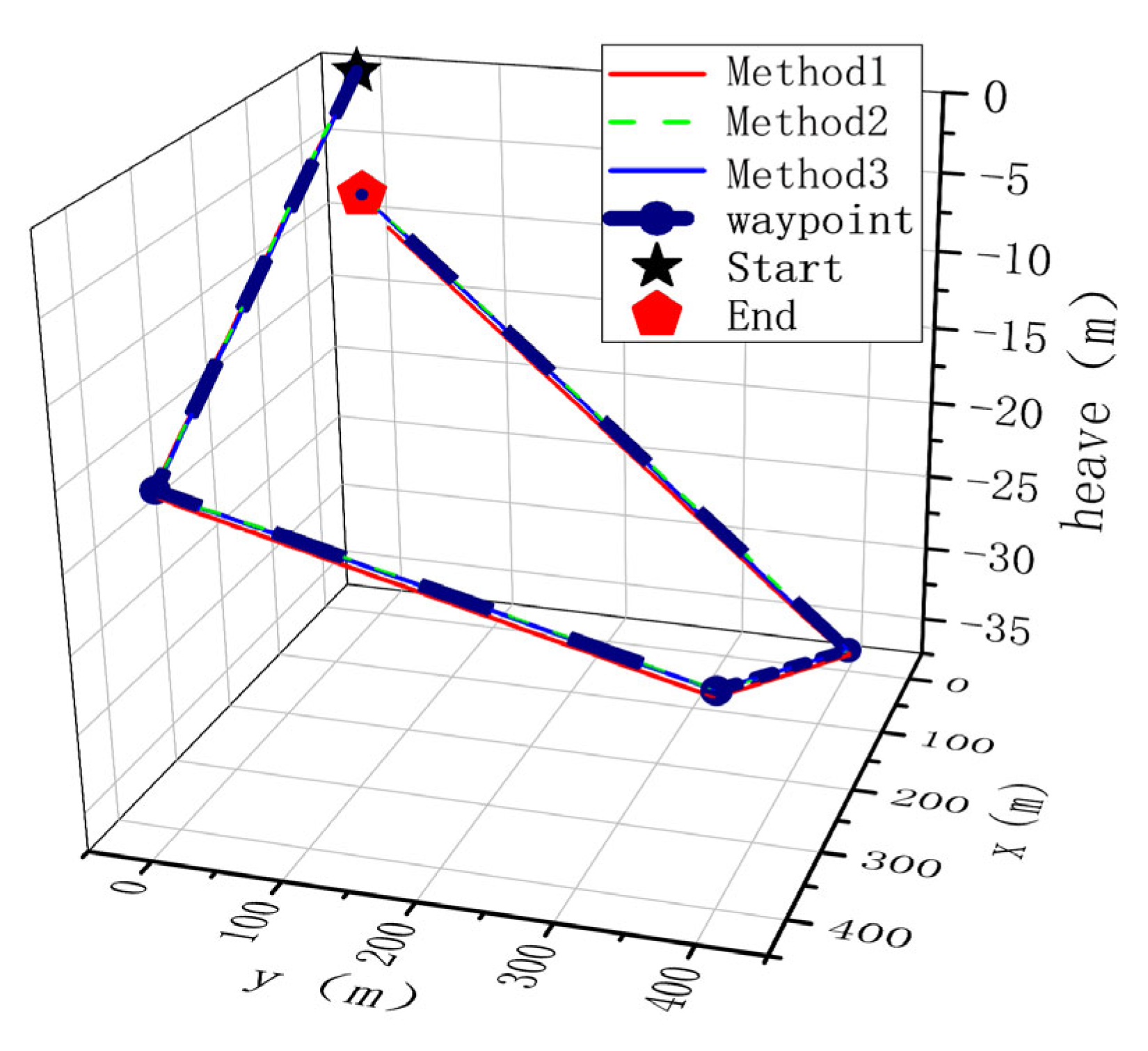
Set path points: (0,0,0), (400,0,−16), (400,400,−24), (0,400,−36), (0,0,−8). ALOS parameters are γ 1 = 0.0006 ,   γ 2 = 0.0006 ,   1 = 20 ,   2 = 6 ,   t = 0.02 ; ILOS parameters: κ = 0.1 ,   1 = 20 ,   2 = 6 ,   t = 0.02 ; LOS parameters: 1 = 20 ,   2 = 6 .
The experimental path is shown in Figure 10. Due to the influence of time-varying ocean currents, there is a deviation between the Method 1 path and the expected path. The horizontal and vertical tracking errors are shown in Figure 11 and Table 5: Affected by ocean currents, the absolute average horizontal and vertical errors of Method 1 are 2.34 m and 0.39 m, respectively, while the absolute average horizontal and vertical errors of Method 3 are reduced by 85.89% and 94.87%, respectively, compared to Method 1. The errors of Method 1 are significantly larger than those of Method 2 and Method 3.
The yaw angle and pitch angle of the AUV’s navigation, as shown in Figure 12a,b, exhibit fluctuations at the turning points for Method 3 and Method 2. These fluctuations are effective actions taken to respond to environmental disturbances. The larger fluctuations in Method 3 compared to Method 2 facilitate faster tracking; The performance of ILOS guidance used in Method 2 and ALOS used in Method 3 is similar under steady-state conditions. However, using the same dynamic controller, the lateral and longitudinal error convergence rates in Method 3 are faster than those in Method 2, indicating that the ALOS guidance law has better tracking capability in compensating for rapid changes caused by time-varying currents.

5. Experiment Results and Discussion

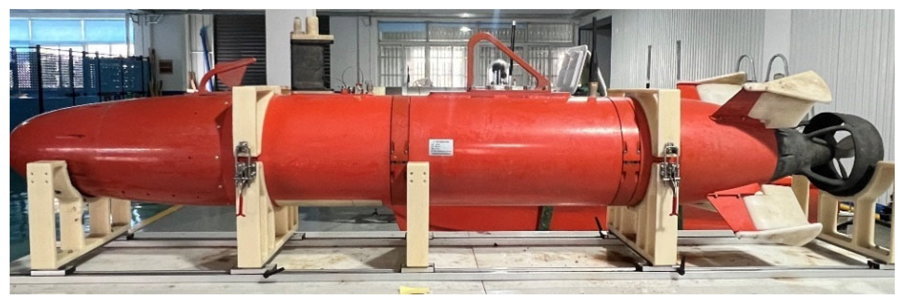
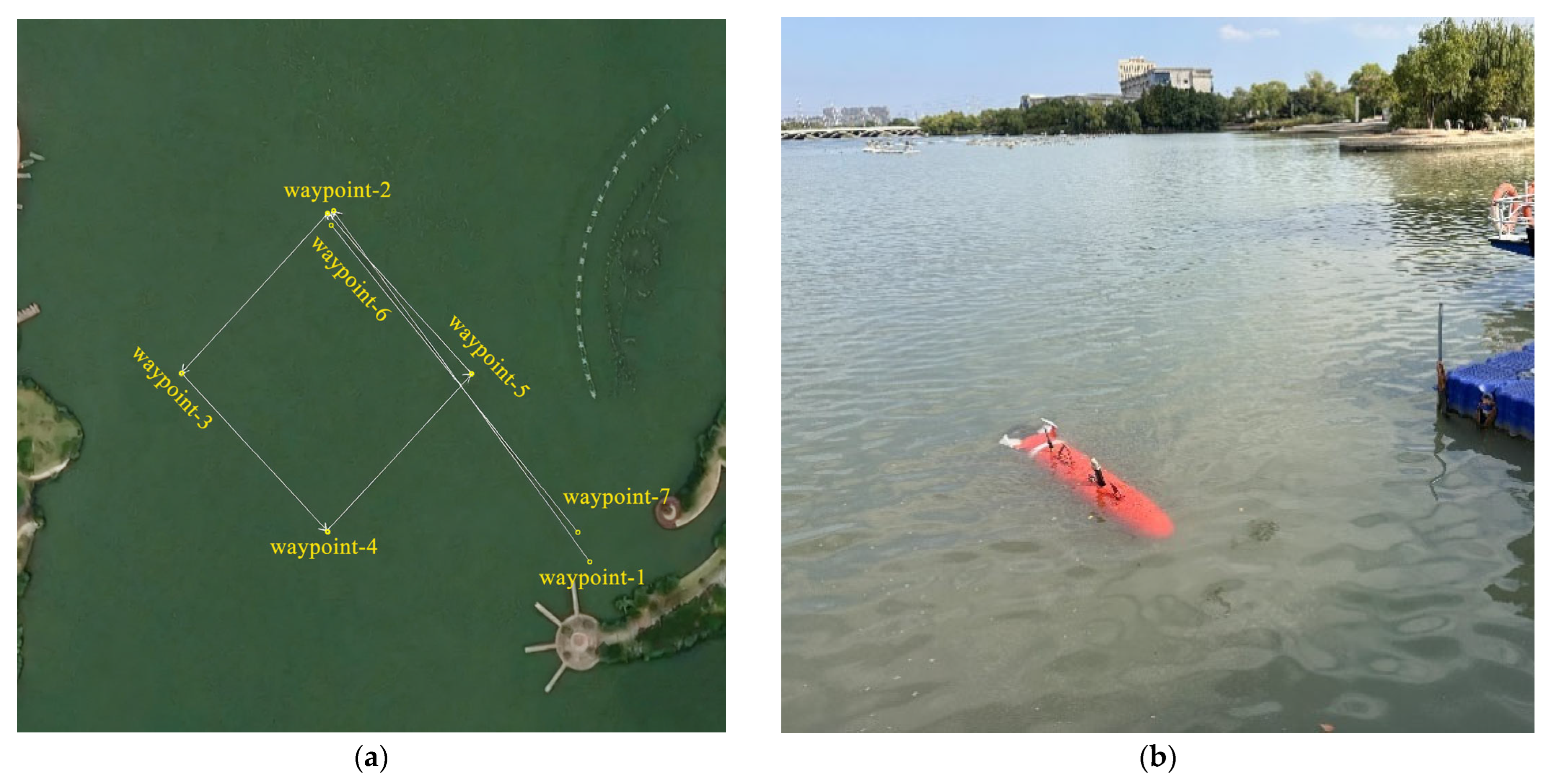
To further investigate the impact of roll coupling on the path tracking of the X-rudder AUV and to verify the stability of the proposed control algorithm, an X-rudder AUV was used, as shown in Figure 13. The test platform was equipped with sensors such as IMU, DVL, and a depth gauge. The AUV conducted spatial path tracking experiments in Shazhou Lake, Zhangjiagang City, as shown in Figure 14a. The expected path is shown in Figure 14a, where the AUV tracks a rectangular path with varying depths underwater. The lake environment is shown in Figure 14b.
The expected waypoint coordinates are: (120.558590, 31.889791), (120.557850, 31.889159), (120.558590, 31.888528), (120.559330, 31.889159), (120.558590, 31.889791). The distance between waypoints is 100 meters, with a depth decrease of 0.4 meters at each waypoint, and a navigation speed of 3 knots.
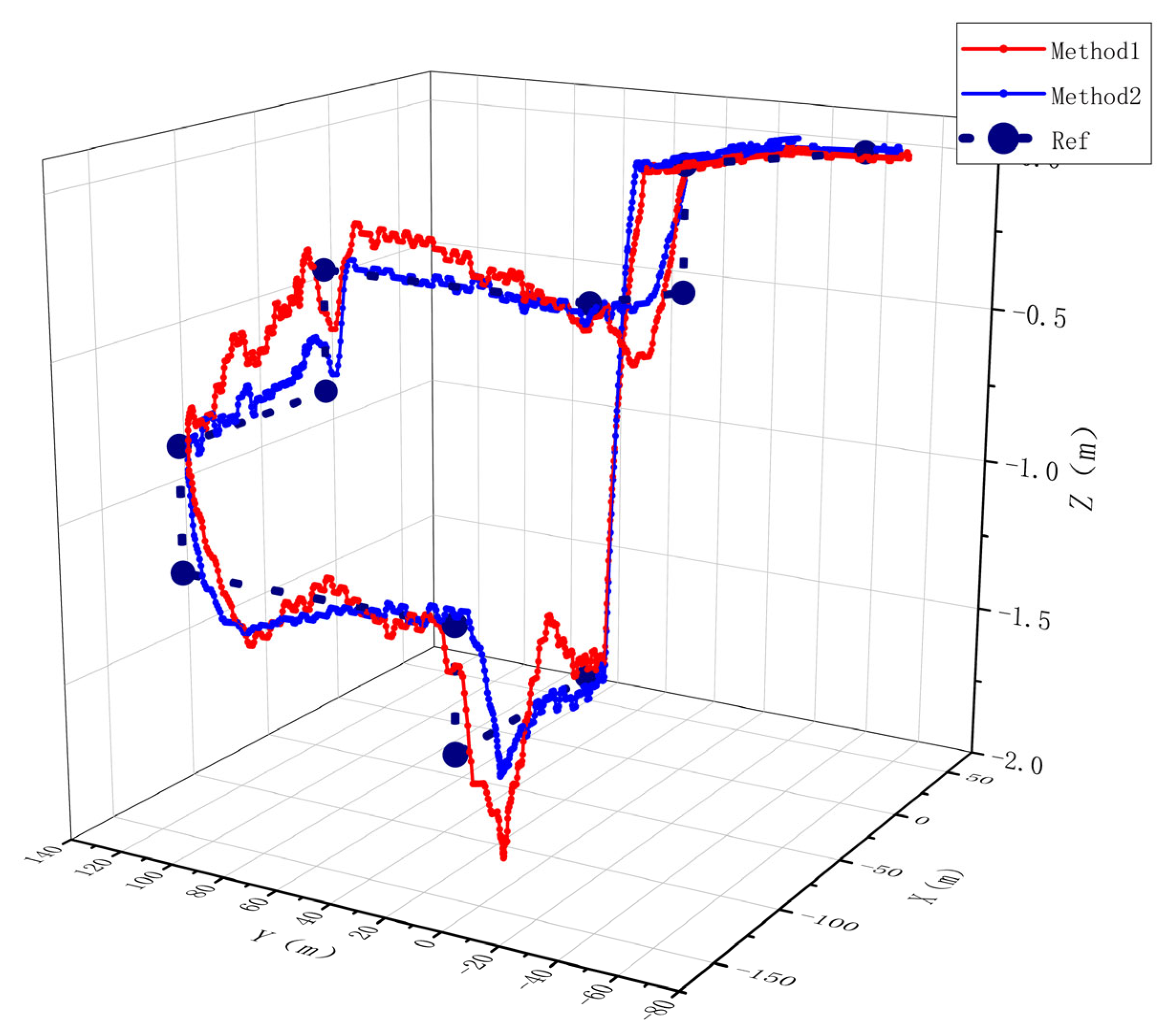
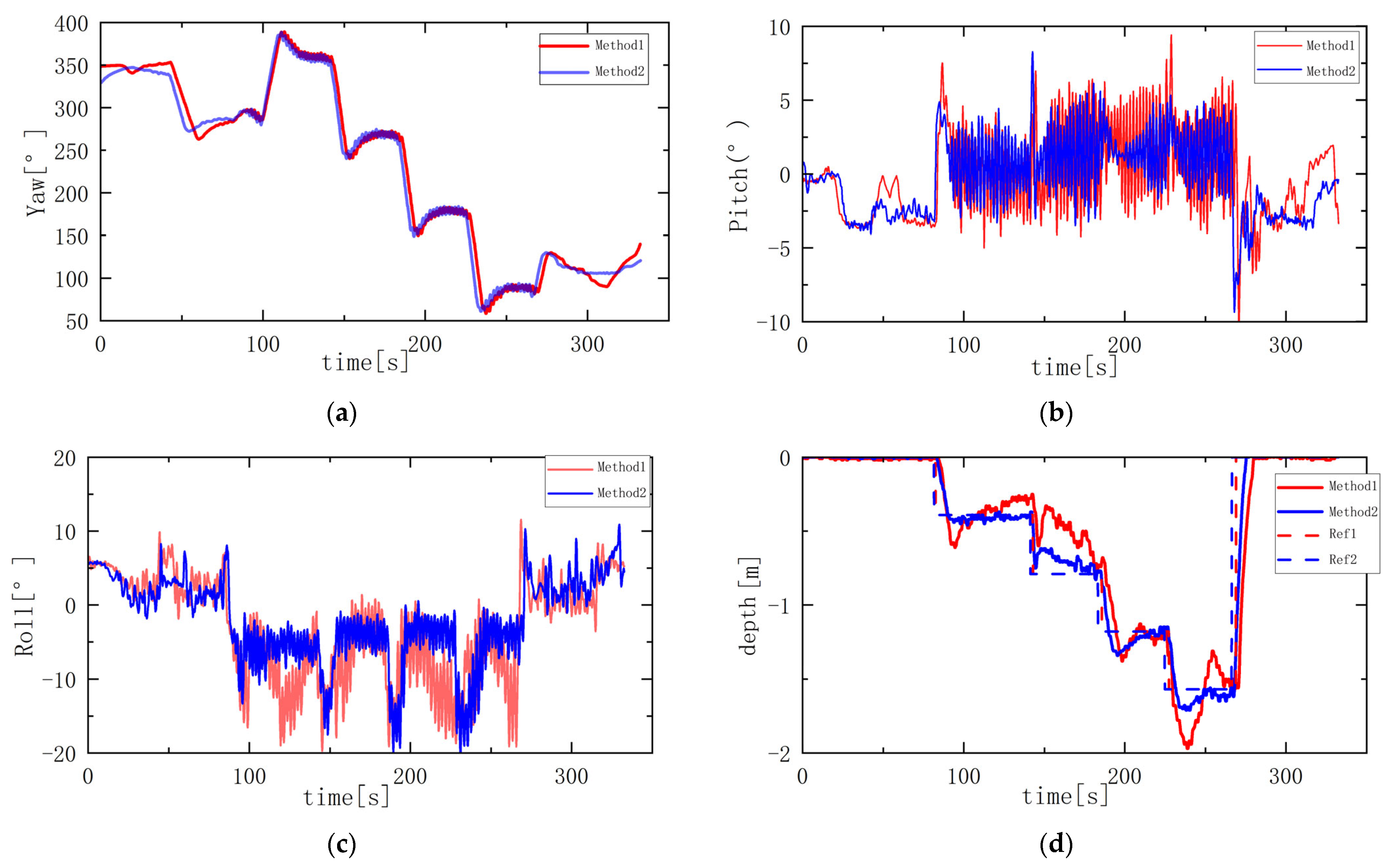
A comparison of path tracking for AUVs with and without roll control is shown in Figure 15. The red curve Method1 represents the path tracking curve without roll control; the blue curve Method 2 represents the path tracking curve with roll control; and the dashed line ref represents the reference path. Analysis shows that AUV path tracking is more stable under roll constraints. The AUV attitude curve is shown in Figure 16. Among them, the roll angle, as shown in Figure 16c, reached a maximum of −19.12° during the descent from 83 s to 273 s, with an average roll angle of −8.63°; The depth control stability shown in Figure 16d is relatively poor, with a maximum error of 0.45 m and an average error of 0.24 m. The pitch angle shown in Figure 16b fluctuates between −5° and 10°, with a variance of 5.21. In contrast, Method 2 demonstrates superior overall performance: the average roll angle is −4.27°, representing a 50.52% reduction compared to Method1. Depth control accuracy has significantly improved, with a maximum error of only 0.17 m and an average error of 0.16 m, a 33.3% reduction. The amplitude of pitch angle oscillations has decreased, with a variance of 1.42. In the yaw angle (Figure 16a), Method 1 and Method 2 exhibit small angular deviations, and Method 1 takes longer to achieve stable convergence than Method 2, demonstrating that the proposed roll-constrained control method exhibits stronger disturbance rejection capability and improved stability in heading and depth control.

6. Conclusions

This paper addresses the spatial path-tracking problem of an X-rudder AUV under random ocean current disturbances and proposes an ALOS guidance–LQR control strategy with roll constraints. By incorporating roll control, ESO-based disturbance estimation, and adaptive guidance, the method effectively suppresses roll-induced coupling effects, compensates for model uncertainties, and mitigates the impact of time-varying ocean current disturbances.
The main conclusions of this study are as follows:
1
In simulations, the roll-constrained LQR controller reduced the lateral and longitudinal absolute mean errors by 14.82% and 54.07%, respectively, compared with the conventional LQR. When combined with the ESO, the errors were further decreased by 77.73% and 80.61%, demonstrating significant improvement in control accuracy under nonlinear and uncertain conditions.
2
Under time-varying ocean current disturbances, the proposed ALOS guidance method reduced lateral and longitudinal errors by 85.89% and 94.87%, respectively, compared with traditional LOS, and achieved faster convergence than ILOS, indicating superior stability and disturbance compensation capability.
3
In physical experiments, roll control reduced the roll angle by 50.52% and the depth error by 33.3%, validating the engineering applicability and effectiveness of the proposed strategy in real-world AUV operations.
In summary, the proposed ALOS-LQR strategy with roll constraints provides a practical and effective solution for enhancing the stability, accuracy, and robustness of AUV path tracking. Nevertheless, in highly dynamic tasks such as aggressive maneuvers, moderate roll motion may actually improve the turning capability of the AUV, which reveals certain limitations of the proposed method. Moreover, the control framework has not yet been fully validated in real ocean environments, and further experimental studies are required. Future work will therefore focus on extending the physical experiments from lake trials to sea environments to evaluate the controller’s performance under more complex conditions.

Author Contributions

Conceptualization, Y.Z. and J.Y.; methodology, Y.Z. and Q.C.; software, Y.Z. and Q.C.; validation, Y.Z., J.Y. and Q.C.; formal analysis, Y.Z.; investigation, Z.Z.; resources, Z.Z.; data curation, Y.Z.; writing—original draft preparation, Y.Z.; writing—review and editing, J.Y. and L.W.; visualization, Y.Z.; supervision, J.Y. and L.W.; project administration, J.Y.; funding acquisition, J.Y. All authors have read and agreed to the published version of the manuscript.

Funding

Specialty Project of Guangdong Provincial Education Department (Intelligent Robot High-end Equipment Manufacturing): 2023ZDZX3004; Maritime Defense Innovation Fund Project: JJ-2023-715-01.

Data Availability Statement

Data are contained within the article.

Conflicts of Interest

The authors declare no conflicts of interest.

References

  1. Orozco-Rosas, U.; Montiel, O.; Sepúlveda, R. Mobile robot path planning using membrane evolutionary artificial potential field. Appl. Soft Comput. 2019, 77, 236–251. [Google Scholar] [CrossRef]
  2. Orozco-Rosas, U.; Picos, K.; Pantrigo, J.J.; Sepúlveda, R.; Montiel, O. Mobile robot path planning using a QAPF learning algorithm for known and unknown environments. IEEE Access 2022, 10, 84648–84663. [Google Scholar] [CrossRef]
  3. González-García, J.; Gómez-Espinosa, A.; Cuan-Urquizo, E.; Herrera-Ruiz, G.; Olivares-Mendez, M.A. Autonomous underwater vehicles: Localization, navigation, and communication for collaborative missions. Appl. Sci. 2020, 10, 1256. [Google Scholar] [CrossRef]
  4. Li, D.; Du, L. AUV Trajectory Tracking Models and Control Strategies: A Review. J. Mar. Sci. Eng. 2021, 9, 1020. [Google Scholar] [CrossRef]
  5. Zhang, B.B.; Ji, D.X.; Liu, S.; Zhu, X.K.; Xu, W. Autonomous Underwater Vehicle navigation: A review. Ocean Eng. 2023, 273, 113861. [Google Scholar] [CrossRef]
  6. Li, S.Q.; Ye, J.M.; Zhang, H.K. Analysis of underwater fixed depth turning characteristic of X-rudder and C-rudder submarine. J. Ship Mech. 2020, 24, 1433–1442. [Google Scholar]
  7. Cao, Z.J.; Xiao, C.R.; Li, S.Q.; Liang, Q.F. Comparative analysis of submarine stability between X-rudder and cross-rudder. Ship Sci. Technol. 2021, 43, 51–55. [Google Scholar]
  8. Petrich, J.; Stilwell, D.J. Robust control for an autonomous underwater vehicle that suppresses pitch and yaw coupling. Ocean Eng. 2011, 38, 197–204. [Google Scholar] [CrossRef]
  9. Ebrahimi, M.; Salehi, S.M. Enhancing the dynamics of an oceanic AUV by a Coupled-Fins-Propulsors roll control system. Ocean Eng. 2021, 234, 109182. [Google Scholar] [CrossRef]
  10. Liu, Z.; Cai, W.; Zhang, M.; Lv, S. Improved Integral Sliding Mode Control-Based Attitude Control Design and Experiment for High Maneuverable AUV. J. Mar. Sci. Eng. 2022, 10, 795. [Google Scholar] [CrossRef]
  11. Tran, H.N.; Pham, T.N.N.; Choi, S.H. Robust depth control of a hybrid autonomous underwater vehicle with propeller torque’s effect and model uncertainty. Ocean Eng. 2021, 220, 108257. [Google Scholar] [CrossRef]
  12. Tanveer, A.; Ahmad, S.M. Cross-Coupled Dynamics and MPA-Optimized Robust MIMO Control for a Compact Unmanned Underwater Vehicle. J. Mar. Sci. Eng. 2023, 11, 1411. [Google Scholar] [CrossRef]
  13. Huang, Z.M.; Cheng, Z. Anti-roll control and maneuverability test of X-rudder autonomous underwater vehicle. Chin. J. Ship Res. 2021, 16, 1–13. [Google Scholar]
  14. He, L.; Xie, M.; Zhang, Y. A Review of Path Following, Trajectory Tracking, and Formation Control for Autonomous Underwater Vehicles. Drones 2025, 9, 286. [Google Scholar] [CrossRef]
  15. Chen, Q.D. Adaptive backstepping control for underactuated AUVs under ocean current disturbances. Ship Sci. Technol. 2025, 47, 138–145. [Google Scholar]
  16. Liao, Y.Z. MPC-DO based trajectory tracking control of autonomous underwater vehicle. Ship Sci. Technol. 2024, 46, 74–80. [Google Scholar]
  17. Lou, J.L. Research on AUV depth control based on linear active disturbance rejection control. Ship Sci. Technol. 2023, 45, 96–101s. [Google Scholar]
  18. Yuan, J.P.; She, Y.; Zhang, Y.; Xu, J.; Wan, L. Research on L 1 Adaptive Control of Autonomous Underwater Vehicles with X-Rudder. J. Mar. Sci. Eng. 2023, 11, 1946. [Google Scholar] [CrossRef]
  19. Duan, Y.; Xiang, X.; Liu, C.; Yang, L. Double-loop LQR depth tracking control of underactuated AUV: Methodology and comparative experiments. Ocean Eng. 2024, 300, 117410. [Google Scholar] [CrossRef]
  20. Wang, S.L.; Ye, X.; Hou, X.; Zhang, R.; Zhao, J. An Improved Real-Time Los-Based Model Predictive Control for the Ocean Bottom Fly Node Under Ocean Disturbances. J. Mar. Sci. Eng. 2025, 13, 725. [Google Scholar] [CrossRef]
  21. Fossen, T.I. Handbook of Marine Craft Hydrodynamics and Motion Control; John Willy & Sons Ltd.: Hoboken, NJ, USA, 2011. [Google Scholar]
  22. Lekkas, A.M.; Fossen, T.I. Integral LOS path following for curved paths based on a monotone cubic Hermite spline parametrization. IEEE Trans. Control Syst. Technol. 2014, 22, 2287–2301. [Google Scholar] [CrossRef]
  23. Huang, Z.M.; Xia, Y.K.; Wang, W.J.; Xu, G.H.; Xiang, X.B.; Xu, K. SHSA-based adaptive roll-safety 3D tracking control of a X-Rudder AUV with actuator dynamics. Ocean Eng. 2022, 265, 112544. [Google Scholar] [CrossRef]
  24. Fossen, T.I. An adaptive line-of-sight (ALOS) guidance law for path following of aircraft and marine craft. IEEE Trans. Control Syst. Technol. 2023, 31, 2887–2894. [Google Scholar] [CrossRef]
  25. Mudassir, M.; Kamal, U.; Aslam, H.; Khan, M.A.; Shah, S.A.A.; Kim, Y.H. Robust Propulsion Control for a Class of X-rudder Autonomous Underwater Vehicle. In Proceedings of the 2022 International Conference on Emerging Trends in Electrical, Control, and Telecommunication Engineering (ETECTE), Istanbul, Turkey, 18–20 November 2022; IEEE: Piscataway, NJ, USA, 2022; pp. 1–6. [Google Scholar]
  26. Ameer, Y.; Kamal, U.; Memon, A.Y. Design of X-rudder AUV’s Motion Control Using Sliding Mode Control with Optimal Rudder Allocation Technique. In Proceedings of the 2022 19th International Bhurban Conference on Applied Sciences and Technology (IBCAST), Islamabad, Pakistan, 20 August 2022; IEEE: Piscataway, NJ, USA, 2022; pp. 938–943. [Google Scholar]
  27. He, L.; Zhang, Y.; Li, S.; Li, B.; Yuan, Z. Three-Dimensional Path Following Control for Underactuated AUV Based on Ocean Current Observer. Drones 2024, 8, 672. [Google Scholar] [CrossRef]
  28. Chen, Q.; Yuan, J.; Dong, Z.; Chai, Z.; Wan, L. Enhanced Control Strategies for Underactuated AUVs Using Backstepping Integral Sliding Mode Techniques for Ocean Current Challenges. J. Mar. Sci. Eng. 2024, 12, 2201. [Google Scholar] [CrossRef]
  29. Han, J. From PID to active disturbance rejection control. IEEE Trans. Ind. Electron. 2009, 56, 900–906. [Google Scholar] [CrossRef]
  30. Vadapalli, S.; Mahapatra, S. 3D Path Following Control of an Autonomous Underwater Robotic Vehicle Using Backstepping Approach Based Robust State Feedback Optimal Control Law. J. Mar. Sci. Eng. 2023, 11, 277. [Google Scholar] [CrossRef]
  31. Wang, Z.; Li, Y.; Ma, C.; Xu, Y.; Yu, H.; Zhang, W. Path-following optimal control of autonomous underwater vehicle based on deep reinforcement learning. Ocean Eng. 2023, 268, 113407. [Google Scholar] [CrossRef]
  32. Fossen, T.I.; Pettersen, K.Y.; Galeazzi, R. Line-of-Sight Path Following for Dubins Paths with Adaptive Sideslip Compensation of Drift Forces. IEEE Trans. Control. Syst. Technol. 2015, 23, 820–827. [Google Scholar] [CrossRef]
  33. Han, J.Q. Auto-Disturbance Rejection Controller and Its Applications. Control Decis. 1998, 13, 19–23. [Google Scholar]
  34. Khalil, H.K.; Grizzle, J.W. Nonlinear Systems, 3rd ed.; Prentice Hall: Upper Saddle River, NJ, USA, 2002. [Google Scholar]
Figure 1. Rolling motion causes the X-rudder AUV’s trajectory to deviate from the desired path. Among them: (a) Deviation between the AUV track and the expected path; (b) Roll angle of the AUV during the experiment.
Jmse 13 01778 g001
Figure 2. Due to the impact of rolling, a serious safety accident occurred during the experiment. Among them: (a) Speed curve; (b) Roll angle affected by thrust torque.
Jmse 13 01778 g002
Figure 3. Establishment of X-rudder AUV coordinate system.
Jmse 13 01778 g003
Figure 4. X-rudder number and force analysis.
Jmse 13 01778 g004
Figure 5. X-rudder AUV motion control block diagram.
Jmse 13 01778 g005
Figure 6. (a) Schematic diagram of AUV pitch guidance using ALOS; (b) Schematic diagram of AUV heading guidance using ALOS.
Jmse 13 01778 g006
Figure 7. The ESO-LQR control strategy with roll control minimizes errors in yaw, pitch, and depth tracking, and provides optimal stability. (a) Yaw response; (b) pitch response; (c) roll response; (d) depth response.
Jmse 13 01778 g007
Figure 8. By increasing the AUV rudder angle output and adopting a differential rudder strategy, environmental interference can be offset, thereby improving tracking accuracy and stability. (a) Rudder 1 curve; (b) Rudder 2 curve; (c) Rudder 3 curve; (d) Rudder 4 curve.
Jmse 13 01778 g008
Figure 9. ESO-LQR controller with roll control effectively reduces tracking error. (a) lateral error; (b) longitudinal error.
Jmse 13 01778 g009
Figure 10. Path tracking. The path tracking of Method 1 has a deviation.
Jmse 13 01778 g010
Figure 11. The horizontal and vertical errors in Method 1 always show deviations; the convergence speed in Method 2 is slower than that in Method 3. (a) lateral error; (b) longitudinal error.
Jmse 13 01778 g011
Figure 12. The Yaw and pitch of Method 3 and Method 2 fluctuate at the turning point. These fluctuations are effective actions taken to respond to environmental disturbances, with Method 3 exhibiting greater fluctuations than Method 2. (a) Yaw response; (b) Pitch response.
Jmse 13 01778 g012
Figure 13. X-rudder AUV.
Jmse 13 01778 g013
Figure 14. (a) Host computer map interface and expected path of AUV; (b) The experimental environment.
Jmse 13 01778 g014
Figure 15. The red curve indicates without roll control; the blue curve indicates roll control. The blue curve’s path is significantly better than the red curve’s, and the tracking error is smaller.
Jmse 13 01778 g015
Figure 16. The control method under roll constraints exhibits stronger interference resistance and stability in heading and depth control. (a) Yaw response; (b) Pitch response; (c) Roll response; (d) depth response.
Jmse 13 01778 g016
Table 1. Basic parameters and hydrodynamic coefficients of the X-rudder AUV.
ParametersValueParametersValueParametersValueParametersValue
ρ 1000 (kg/m3) X u u −1.428 Y u r 3.834 M q q −112.4
m 156.5 (kg) X w q −26.08 Z w ˙ −26.08 M w w 2.107
L 2.3 (m) X q q −1.279 Z w w −96.22 M u w 1.591
B 107.9 (N) X v r −26.08 Z q q −41.9 M u q −1.325
I x x 0.016 (kg·m2) X r r −1.279 Z u w −21.01 N r ˙ −2.918
I y y 0.8 (kg·m2) Y v ˙ −26.08 Z u q −3.834 N r r −56.21
I z z 0.8 (kg·m2) Y v v −96.22 K p p −0.078 N v v −2.107
Z b 0.0296 Y r r −0.419 K p ˙ −0.042 N u v −1.591
X u ˙ −0.683 Y u v −21.01 M q ˙ −2.918 N u r −1.325
Table 2. Different controller for comparison.
NameMethod
Method 1LQR
Method 2LQR with Roll Control
Method 3ESO+LQR with Roll Control
Table 3. Statistics of Lateral and Longitudinal Errors and Roll Angles for Different Methods.
Name y e  Maximum y e MAE z e  Maximum z e MAERoll MaximumRoll MAE
Method 10.140.0410.080.03418.6015.53
Method 20.120.0350.050.0157.222.72
Method 30.020.0070.010.0033.392.47
Table 4. Different controller for comparison.
NameMethod
Method 1LOS+ESO+LQR with Roll Control
Method 2ILOS+ESO+LQR with Roll Control
Method 3ALOS+ESO+LQR with Roll Control
Table 5. Statistics of Lateral and Longitudinal Errors for Different Methods.
Name y e  Maximum y e MAE z e  Maximum z e
Method 15.302.340.720.390
Method 24.970.390.340.055
Method 34.980.330.310.023
Disclaimer/Publisher’s Note: The statements, opinions and data contained in all publications are solely those of the individual author(s) and contributor(s) and not of MDPI and/or the editor(s). MDPI and/or the editor(s) disclaim responsibility for any injury to people or property resulting from any ideas, methods, instructions or products referred to in the content.