Article

Coupled Simulation Study on the High-Pressure Air Expulsion from Submarine Ballast Tanks and Emergency Surfacing Dynamics

Naval University of Engineering, Wuhan 430033, China
*
Author to whom correspondence should be addressed.
J. Mar. Sci. Eng. 2025, 13(9), 1769; https://doi.org/10.3390/jmse13091769
Submission received: 10 August 2025 / Revised: 7 September 2025 / Accepted: 9 September 2025 / Published: 13 September 2025
(This article belongs to the Special Issue Advanced Studies in Ship Fluid Mechanics)

Abstract

Emergency surfacing acts as the final line of defense in preserving the operational viability of submarines, playing a crucial role in their safety. To investigate the dynamic characteristics of submarine emergency surfacing, utilizing whole moving mesh technology, a method for coupled simulation of high-pressure air blowing out water tanks and emergency surfacing motion of submarines is proposed, enhancing the simulation’s fidelity to real-world dynamics. Based on meeting the requirements for simulation accuracy, utilizing the coupled simulation model, this study explored the effects of varying expulsion pressures on submarine motion parameters including depth, roll, pitch, and yaw angles. The findings indicate that the hull emerges slightly earlier and reaches a marginally higher point when coupling effects are accounted for compared to scenarios where these effects are neglected. At consistent expulsion pressures, as the pitch and roll angles increase and the back pressure decreases, the expulsion rate from the ballast tank accelerates. Higher expulsion pressures result in quicker surfacing of the hull, smaller amplitude of pitch angles, and larger amplitudes of roll angles, while the changes in yaw angle displayed no clear pattern. The methodologies and conclusions of this study offer valuable insights for the design and operational strategies of actual submarines.

1. Introduction

In the challenging environment of underwater navigation, submarines or UUVs [1] may confront critical emergencies, such as perilous longitudinal inclinations due to rudder malfunctions or substantial depth reduction precipitated by an “underwater cliff.” In instances where conventional interventions—including cessation of movement, speed adjustments, operation of the surfacing rudder, and ballast equalization—fail to facilitate ascent, the commander is compelled to decisively mandate the deployment of high-pressure air to purge the main ballast tanks, thereby initiating emergency surfacing. Consequently, emergency surfacing constitutes the ultimate safeguard for submarine survivability, with high-pressure air serving as an essential support mechanism. This process primarily involves the expulsion of water from the main ballast tanks using high-pressure air, which swiftly generates significant positive buoyancy, thereby rapidly counteracting the downward momentum and facilitating surfacing. This maneuver is characterized by its dynamic nature, manifesting substantial alterations in the submarine’s attitude, including pronounced fluctuations in roll and pitch angles. Improper handling during this procedure can precipitate capsizing and result in catastrophic outcomes. Therefore, the study of the dynamics of submarine emergency surfacing is imperative for ensuring the operational safety and stability of this procedure.
Having undergone years of development, substantial research has been devoted to the study of submarine emergency surfacing. Common methodologies for predicting the motion during surfacing involve the derivation of hydrodynamic coefficients through model testing [2,3,4] and the subsequent formulation of a six-degree-of-freedom (6-DOF) motion mode, anchored in the 6-DOF equations of motion [5]. Some researchers have integrated models of high-pressure air blowout dynamics for ballast tanks with these 6-DOF submarine motion models to scrutinize the characteristics of emergency surfacing maneuvers [6,7]. However, the acquisition of accurate hydrodynamic coefficients, essential for these methods, is increasingly challenging due to the evolution of submarine designs. Furthermore, the 6-DOF equations of motion, either originally proposed by Gertler [8] or subsequently modified, are predominantly tailored for scenarios involving minimal maneuvering and exhibit considerable limitations in their capacity to predict vigorous maneuvers, such as emergency surfacing. Additionally, these simulation techniques generally yield only temporal sequences of motion parameters, thereby complicating the visualization of the submarine’s surfacing dynamics.
In light of these challenges, some scholars have opted to conduct direct model tests to explore the characteristics of emergency surfacing [9,10,11]. However, such model tests are constrained by high costs and often extensive preparation periods. With the rapid advancement of Computational Fluid Dynamics (CFD) technology, its application in simulating the emergency surfacing motion of submarines has gained substantial prominence. Employing CFD software to directly simulate this motion not only facilitates the acquisition of motion parameters but also enables the visualization of surfacing scenarios through either post-processing or real-time monitoring, thus addressing the limitations inherent in traditional methods reliant on hydrodynamic coefficients and direct model testing.
In recent years, a substantial body of scholarship has emerged, focusing on the simulation of the emergency surfacing behavior of submarines using CFD methodologies, yielding significant insights. Wang et al. [12] investigated the influence of ocean currents on the surfacing of submarines by employing a 6-DOF model alongside CFD simulations, based on the Reynolds-Averaged Navier–Stokes (RANS) equations and overset grids. Their findings indicated that the velocity of currents markedly influences both the fluctuations in surfacing velocity and the pitch angle of the submarine. Zhang et al. [13] extended this line of inquiry by numerically simulating the surfacing motion of a submarine in regular waves, using a similar 6-DOF CFD model. They discovered that both wave height and length significantly affect the surfacing velocity and roll angle, with the maximum roll angles exhibiting an almost linear increase with these wave parameters. However, both studies calculated buoyant force by simply contrasting gravitational and buoyant forces, neglecting the temporal dynamics of buoyant force generation. Subsequent investigations by Chen et al. [14,15] and Zhang et al. [16] involved model experiments and CFD simulations using overset grids to assess roll stability during the buoyant emergence of submarines. Yet, these studies did not account for the interactions between the high-pressure air ejection of water from the ballast tanks and the emergency buoyant ascent motion. Wei et al. [17] developed a numerical prediction method for the emergency ascent of submarines with flow holes in calm water, utilizing sliding and overlapping grids, 6-DOF and DFBI models Their study investigated the effects of positive buoyancy, center of gravity positions, and diving depths on the submarine’s ascent motion. In the ensuing research endeavors, Wei et al. [18] conducted a numerical study on the floating movement of submarines with water holes in wave conditions utilizing an analogous methodology, exploring the influence of wave directions, heights, and wavelengths on submarine buoyancy and stability during emergency ascent. Notably, in their studies, positive buoyancy was predominantly predetermined as a fixed percentage of the submarine’s displacement, without integrating the dynamics of high-pressure water ejection from the ballast tanks. Finally, Guo et al. [19] investigated the influence of unsteady forces on the roll characteristics of a submarine during free ascent from great depths using the SST-DDES model and overset mesh technique. They found that unsteady rolling moments and lateral forces significantly affect roll stability. In alignment with the aforementioned studies, this research also prescribes positive buoyancy artificially, without considering the process of expelling water from the ballast tanks using high-pressure air or the generation of buoyant force.
The extant research on submarine surfacing simulations has primarily employed RANS equations along with overset grids. These studies have integrated such models with 6-DOF motion models or Dynamic Fluid–Body Interaction (DFBI) frameworks to examine the surfacing maneuvers of submarines. This body of research has explored the influence of various parameters and factors on the emergency surfacing trajectories of submarines by employing the methodologies thus described. Nonetheless, these analyses have generally simulated buoyancy achievement through either a reduction in submarine mass or via exogenous conditions, treating the application of buoyancy as an instantaneous event. In reality, the expulsion of water from the main ballast tanks using high-pressure air takes a certain amount of time and cannot be achieved instantaneously. Consequently, the buoyancy load is applied progressively over time to the hull, and the ballast tanks in actual submarines are typically compartmentalized, allowing for sectional expulsion based on specific circumstances. Furthermore, as the submarine undergoes emergency surfacing, the changes in depth affect the back pressure in the expelled tanks, which in turn influences the roll and pitch angles during surfacing. These dynamics affect the efficacy of the high-pressure air expulsion, thus impacting the application of buoyancy forces and subsequently altering the submarine’s motion parameters such as depth, pitch, and roll in a cyclic manner. Therefore, a coupling exists between the high-pressure air expulsion from the water tanks and the emergency surfacing motion of the submarine, with mutual influences between the two. However, prior studies have not accounted for this interplay, leading to conclusions with notable limitations. To more accurately reflect real-world conditions, further research into the coupling of high-pressure air blowing out ballast tanks and the emergency surfacing motion of submarines is necessary.
To enhance the precision of investigations into the dynamics of submarine emergency surfacing motions, this study examines the temporal aspects of buoyancy forces, the sectional expulsion of ballast from tanks, and the coupling between high-pressure air expulsion and submarine emergency surfacing. A novel simulation approach, integrating the RANS equations and full moving mesh technology, has been developed to concurrently simulate the expulsion of high-pressure air from water tanks and the resultant submarine emergency surfacing motions. This coupled simulation methodology facilitates real-time exchange of motion parameters, including depth, roll angle, and pitch angle, between the high-pressure air expulsion model and the emergency surfacing motion model, thereby enhancing the fidelity of submarine emergency surfacing simulations. By applying this method, this study explores the characteristics of emergency surfacing motions under different expulsion pressures. Consequently, this research addresses a significant gap in the coupled simulation of high-pressure air expulsion and submarine emergency surfacing motions, offering substantial contributions to the detailed analysis of submarine surfacing motions.

2. Simulation Model

2.1. Research Subject

The subject of study for the emergency surfacing of submarines is the publicly available Suboff model with a full appendage configuration as disclosed by the Defense Advanced Research Projects Agency (DARPA). The primary dimensions of the model are as follows: total length is 4.356 m, forebody length is 1.016 m, parallel midbody length is 2.229 m, and afterbody length is 1.111 m, with a maximum body diameter of 0.508 m [20]. The geometric model and coordinates are illustrated in Figure 1, and the main parameters of the model are listed in Table 1.
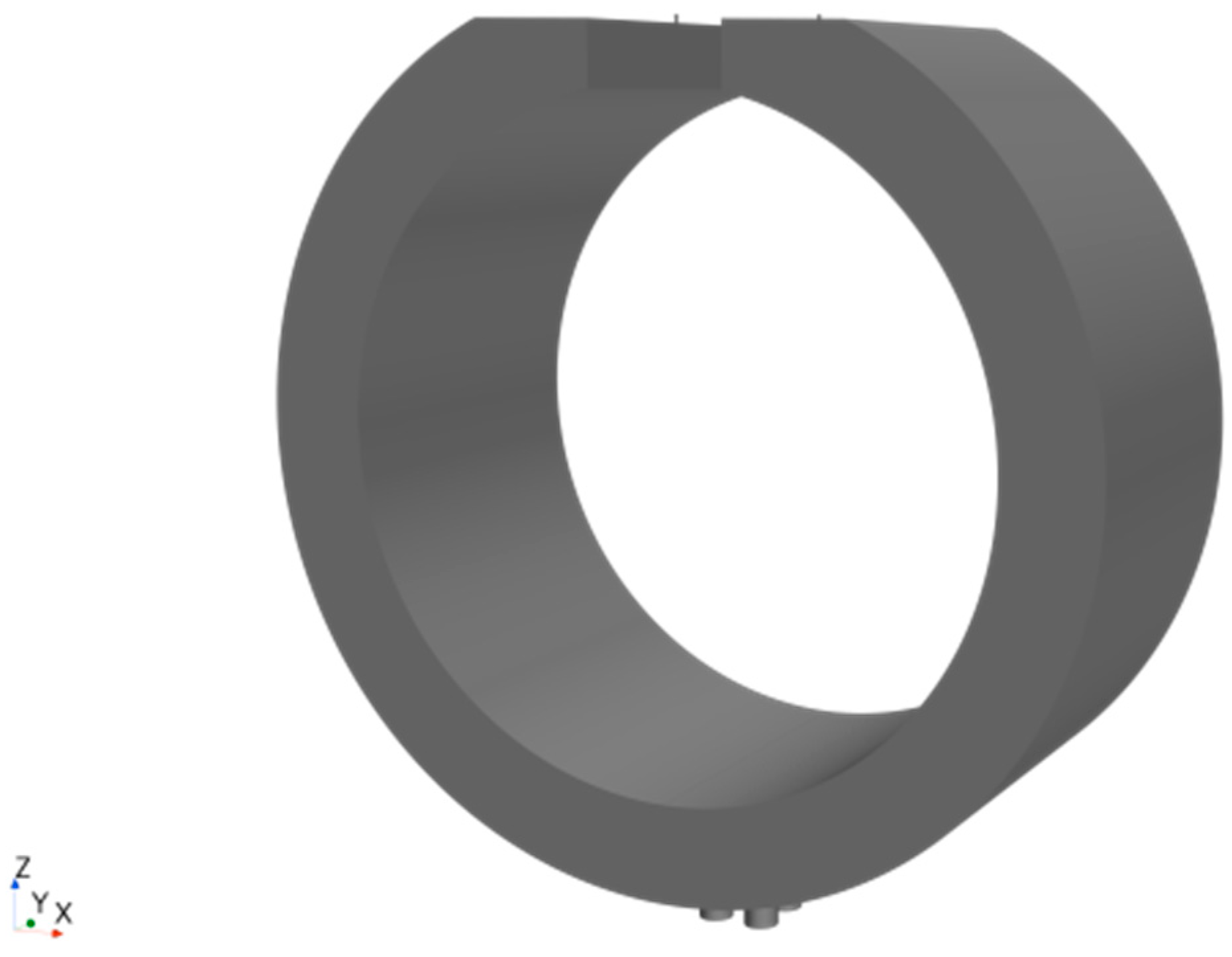
The main ballast tanks of a double-hull submarine are strategically positioned within the inter-hull space and are organized in groups along the longitudinal axis of the submarine. It is posited that Suboff exemplifies a double-hull submarine, wherein three groups of main ballast tanks are longitudinally positioned within the inter-hull space across the hull, specifically at the bow, center, and stern. Each cluster consists of three contiguous tanks. To conform to the hull dimensions of Suboff and to ensure the provision of adequate reserve buoyancy, as depicted in Figure 2, the single ballast tank, having an external diameter of 0.508 m and an internal diameter of 0.4 m with a width of 0.2 m, is symmetrically equipped with two high-pressure air inlets at the upper central position, each with a diameter of 0.002 m, and four circular sea holes at the bottom, each with a diameter of 0.02 m.

2.2. Computational Domain Setup

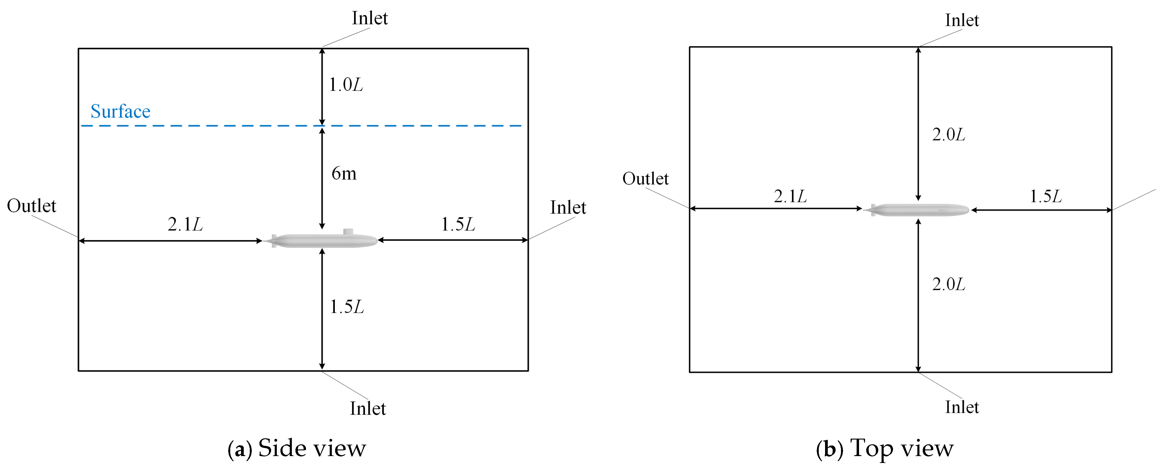
The computational domain for the emergency surfacing motion of the Suboff is set as a square domain, with dimensions and boundary conditions illustrated in Figure 3 (where L denotes the hull length).
The domain includes the walls of the ballast tanks depicted in Figure 2, the high-pressure air inlets, and the sea holes, forming an internal flow field. Due to the symmetrical nature of the ballast tanks, the computational domain is reduced to half to decrease computational load. As shown in Figure 4, a stagnation inlet is established at the high-pressure air inlets allowing for the input of air pressure, while pressure outlets are set at the sea holes. The bottom center longitudinal section serves as a symmetrical plane, with all other surfaces defined as wall boundaries.

2.3. Mesh Partitioning

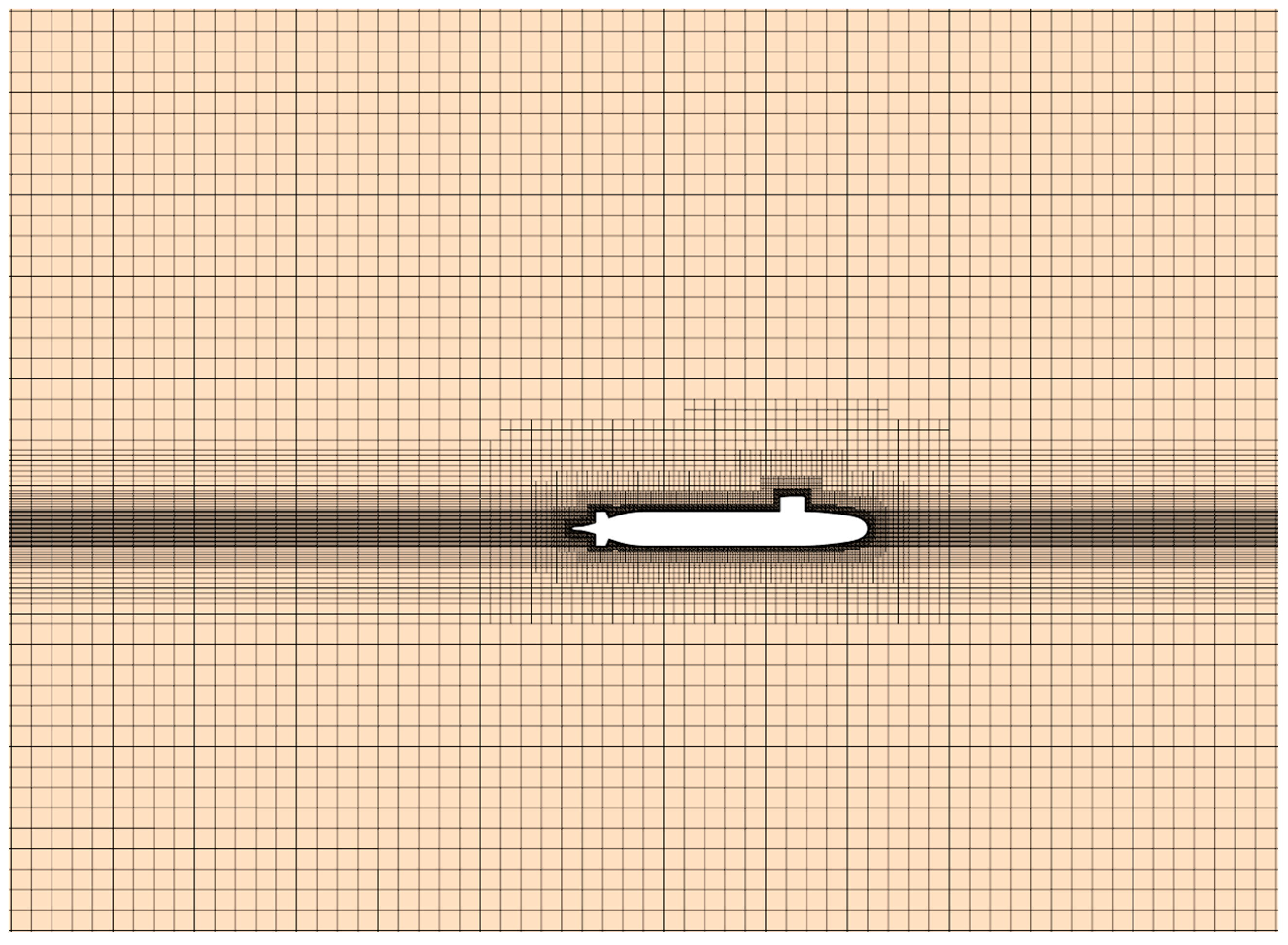
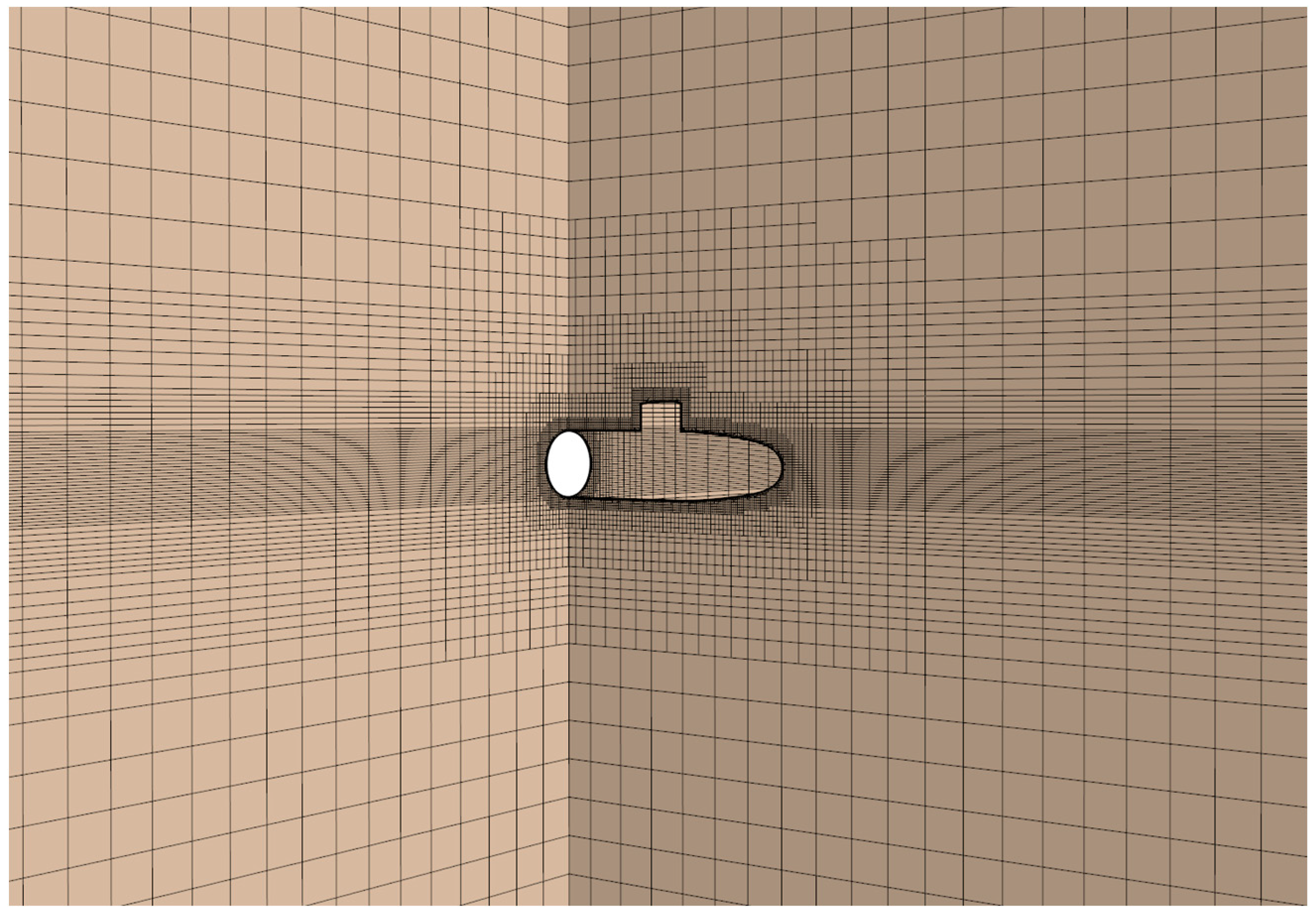
The technique of whole moving mesh is employed for the spatial discretization during the emergency surfacing of the hull. The computational domain moves in conjunction with the hull, while the water surface remains fixed relative to the ground. This approach not only conserves computational resources compared to the overset grids used in the aforementioned research but also ensures the discretization accuracy of the mesh, making it suitable for numerical simulations involving long-distance spatial movements. Specifically, the mesh is partitioned using the Trimmer mesh, a proprietary feature of STAR CCM+ that facilitates adaptive mesh adjustments. This technology allows for automatic reconstruction and surface repair of the hull, enhancing the quality of the mesh. Further refinements are achieved through face control, prism layers, and mesh refining, thus improving the mesh partitioning accuracy for complex models. For hydrodynamic computations, the accuracy of this method is comparable to that of structured meshes. As shown in Figure 5, based on the overall mesh partitioning, areas of significant curvature changes undergo additional mesh refining. Given that the submarine needs to surface, consideration must be given to the free surface, which exhibits complex flow dynamics. To better capture the behavior of the free surface, mesh refinement is also applied to this area. However, since the mesh moves with the hull and the water surface is fixed, the refinement of the free surface mesh must be configured near the hull, as illustrated in Figure 6, enabling precise capture of surface wave dynamics upon the hull’s surfacing.
The mesh for the high-pressure air expulsion from the ballast tank model also utilizes the Trimmer mesh, with refinements around the high-pressure air inlet and sea holes, as shown in Figure 4. Considering the effects of the hull’s pitch and roll angles on the ballast tank during high-pressure air expulsion, the ballast tank in the simulation must rotate in real time in response to the pitch and roll movements of the hull. Consequently, the ballast tank also employs the whole moving mesh approach, allowing the entire computational domain to rotate.

3. Numerical Simulation

3.1. Governing Equations

The governing equations consist of the continuity equation and the RANS equations, which are utilized to model unsteady, three-dimensional, incompressible flow [21]. The continuity equation is represented as follows:
U i x i = 0
The velocity U is composed of a mean velocity component and a fluctuating velocity component, detailed in the following:
U i = U ¯ i + u i
The momentum equations are formulated as follows:
U t + ( U i U j ) x j = 1 ρ P x i + x j ν U i x j + U j x i u i u j ¯ x j
Here, U ¯ i represents the time-averaged velocity, u i denotes the fluctuating velocity, and u i u j ¯ refers to the Reynolds stress, which is associated with the fluctuating velocity.
For numerical discretization, the convective terms are approximated using a second-order upwind difference scheme, while the dissipative terms employ a central difference scheme. The coupling between pressure and velocity is addressed using the SIMPLE method.

3.2. Turbulence Model

The emergency surfacing motion of the submarine, along with the high-pressure air expulsion from the ballast tanks, is modeled using the SST k-ω turbulence model [22]. The SST k-ω model is particularly effective due to its ability to handle adverse pressure gradients and separated flows. Furthermore, the SST k-ω turbulence model utilized in this research is classified as a low-Reynolds-number model, making it suitable for near-wall treatments. Given the considerable flow separation that occurs during the submarine’s emergency surfacing maneuver, the SST k-ω turbulence model was chosen for its capability to accurately capture the complex flow field.
The model demonstrates superior performance compared to the standard k-ω and k–ε models. The mathematical expressions for the model are as follows:
t ρ k + x i ρ k u i = x j Γ k k x j + G k - Y k + S k
t ρ ω + x i ρ ω u i = x j Γ ω ω x j + G ω - Y ω + S ω
In these equations, k represents the turbulent kinetic energy, ω denotes the specific rate of dissipation of turbulent kinetic energy, Γk and Γω are the effective diffusion coefficients for k and ω, respectively. Gk and Gω are the production terms for k and ω, Yk and Yω are the dissipation terms, and Sk and Sω are custom source terms.

4. Validation of Results’ Effectiveness

4.1. Mesh-Independence Analysis

Under identical mesh partitioning and refinement protocols, the accuracy of hydrodynamic numerical computations exhibits a certain positive correlation with mesh density within a defined range. Insufficient mesh density compromises precision, whereas excessively high mesh density significantly escalates computational costs and duration. Thus, before initiating formal numerical computations, it is essential to conduct a mesh-independence analysis to ascertain an optimal mesh size and quantity.
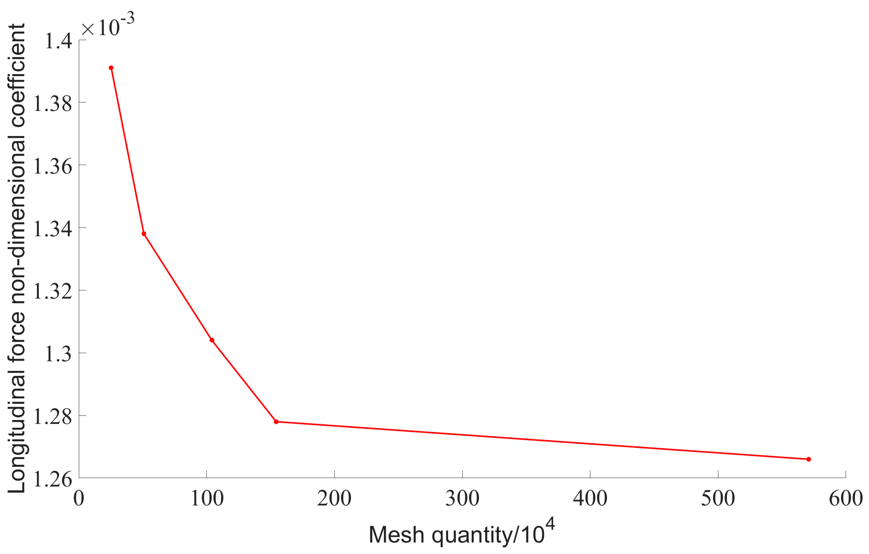
Following the mesh partitioning and refinement procedures, based on the ITTC Recommended Procedures [23], a mesh refinement ratio of 2 in three directions was chosen. Five fundamental mesh sizes were set, with the emergency surfacing motion model mesh based on 0.1 m, and the high-pressure air expulsion ballast tank model mesh based on 0.002 m. The mesh sizes and quantities are displayed in Table 2.
At a constant speed of 3.34 m/s, with the hull maintaining a 0° angle of attack and steady depth under submerged conditions, the hull experiences longitudinal resistance due to the water flow, referred to simply as longitudinal force. For ease of comparative analysis, the longitudinal force was nondimensionalized:
X = X / ( 0.5 ρ U 2 L p p 2 )
where X′ denotes the nondimensional coefficient of longitudinal force; X represents the actual longitudinal force experienced by the hull; LPP is the length between perpendiculars of the hull, taken as 4.261 m; U is the flow velocity at 3.34 m/s.
For the emergency surfacing motion model, the calculated nondimensional coefficients of longitudinal force under the five mesh sizes are illustrated in Figure 7. As the mesh count increases, the total resistance progressively decreases, with the results for 1.544 million and 5.708 million meshes showing close proximity, indicating minimal influence of mesh size on simulation outcomes. Given considerations of computational resources and accuracy, the emergency surfacing motion model opted for a mesh count of 1.544 million, corresponding to a fundamental mesh size of 0.05 m, for subsequent simulations.
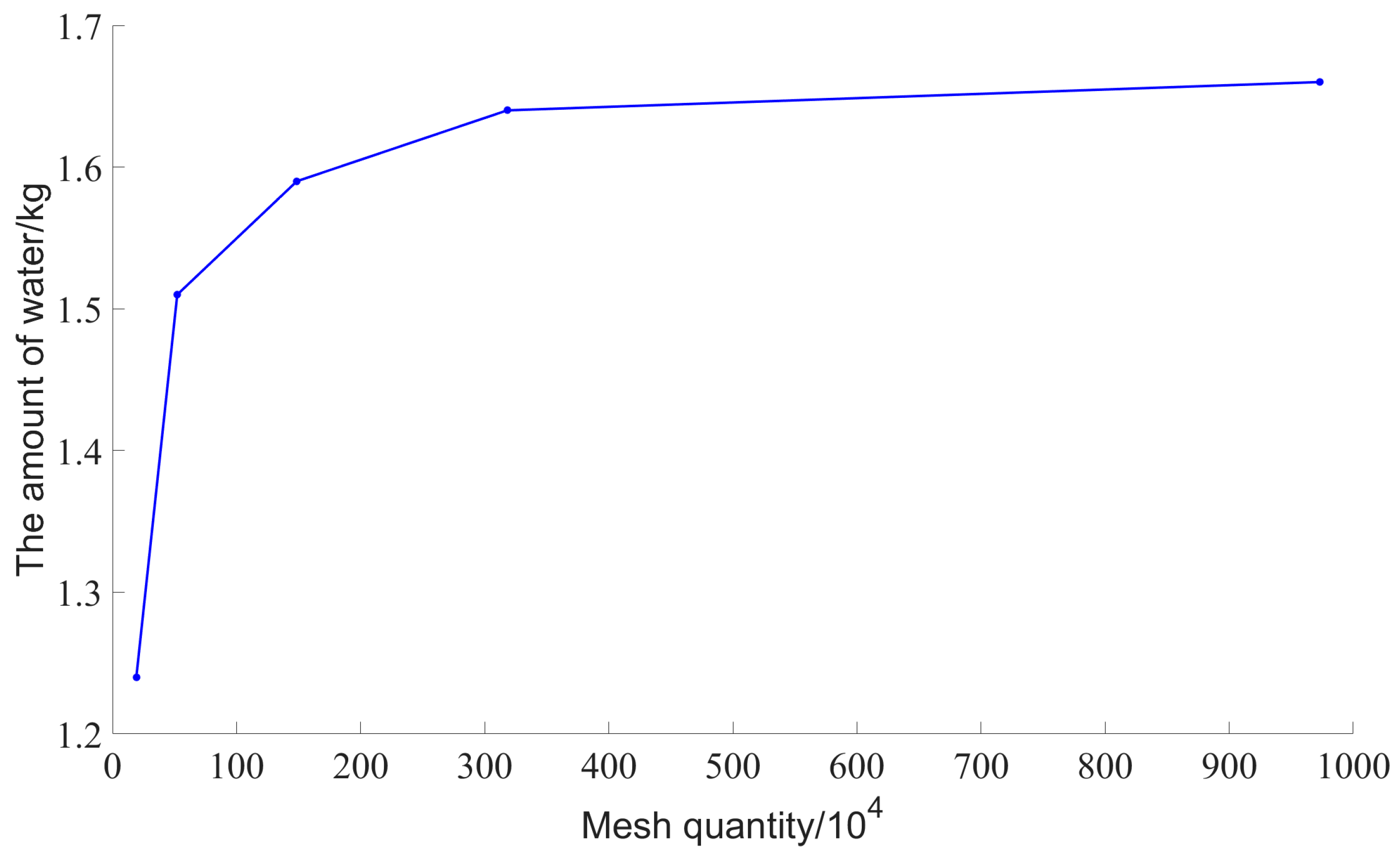
In the modeling of ballast tanks subjected to high-pressure air expulsion, the inlet pressure of the high-pressure air was set at 1.0 MPa, and the outlet back pressure was maintained at 0.06 MPa. Simulations were conducted under five different mesh sizes. At the point where the expulsion duration reached 0.5 s, the volume of water expelled from a single ballast tank is depicted in Figure 8. As the number of meshes increased, there was a corresponding incremental increase in the volume of water expelled. Notably, the simulation results for mesh counts of 318.1 million and 973.1 million were closely aligned, indicating that the influence of mesh size on the simulation outcomes was minimal. Consequently, taking into account both computational resources and accuracy, a mesh count of 318.1 million was selected for the model of the high-pressure air expulsion ballast tank. This count corresponds to a fundamental mesh size of 0.0015 m for subsequent simulation calculations.

4.2. Validation of Simulation Accuracy

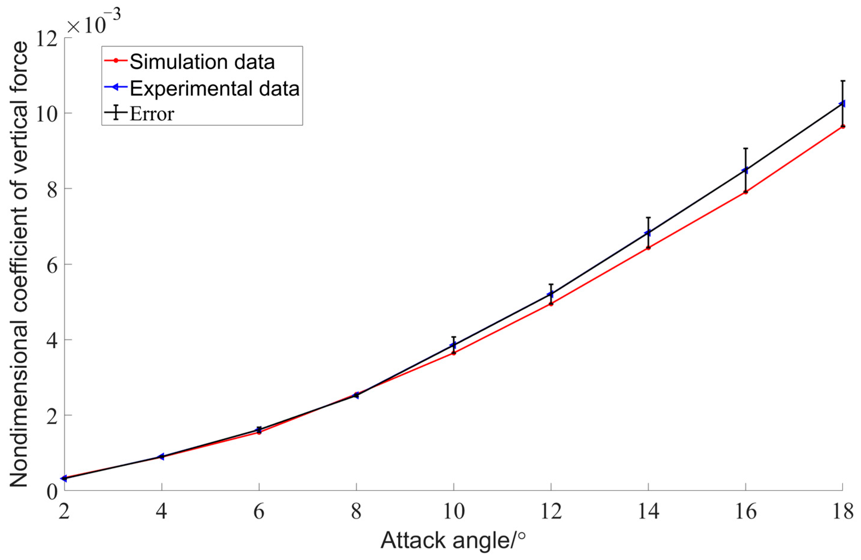
Given the absence of published experimental data on the emergency surfacing of the Suboff submarine using high-pressure air blowing directly into the ballast tank, direct validation of the model’s accuracy by comparing simulation data with experimental results is not feasible. To address this, the dynamic emergency surfacing motion, characterized by a continuously changing angle of attack, can be approximated by discretizing it into a series of steady states at various angles of attack. The David Taylor Research Center has conducted hydrodynamic experiments on the Suboff model at different angles of attack. Utilizing the experimental conditions documented in [24], calculations of vertical force and pitching moment at varying angles of attack can be performed to assess and validate the accuracy of the emergency surfacing simulation model. The inflow velocity, U, is set at 3.34 m/s, the submarine model is fixed, and the angle of attack, α, varies from 2° to 18° in 2° increments for these simulations. All other conditions match those used in the aforementioned model for predicting submarine emergency surfacing.
Additionally, for ease of data comparison and analysis, the relevant physical quantities were nondimensionalized as follows:
Z = Z / ( 0.5 ρ U 2 L p p 2 )
M = M / ( 0.5 ρ U 2 L p p 3 )
where Z and M represent the nondimensional coefficients for vertical force and pitching moment, respectively; Z and M are the vertical force and pitching moment experienced by the hull; L p p represents the length between perpendiculars of the submarine.
As shown in Figure 9 and Figure 10, and detailed in Table 3 and Table 4, the comparison of simulation values with experimental data [24] demonstrates that within the angle of attack range from 2° to 18°, the maximum relative errors in the calculated vertical force coefficient and pitching moment coefficient are 6.8% and 8.3%, respectively. These error margins confirm that the computational model satisfies the necessary accuracy standards, thus supporting the continuation of further simulations of emergency surfacing maneuvers based on this validated model.
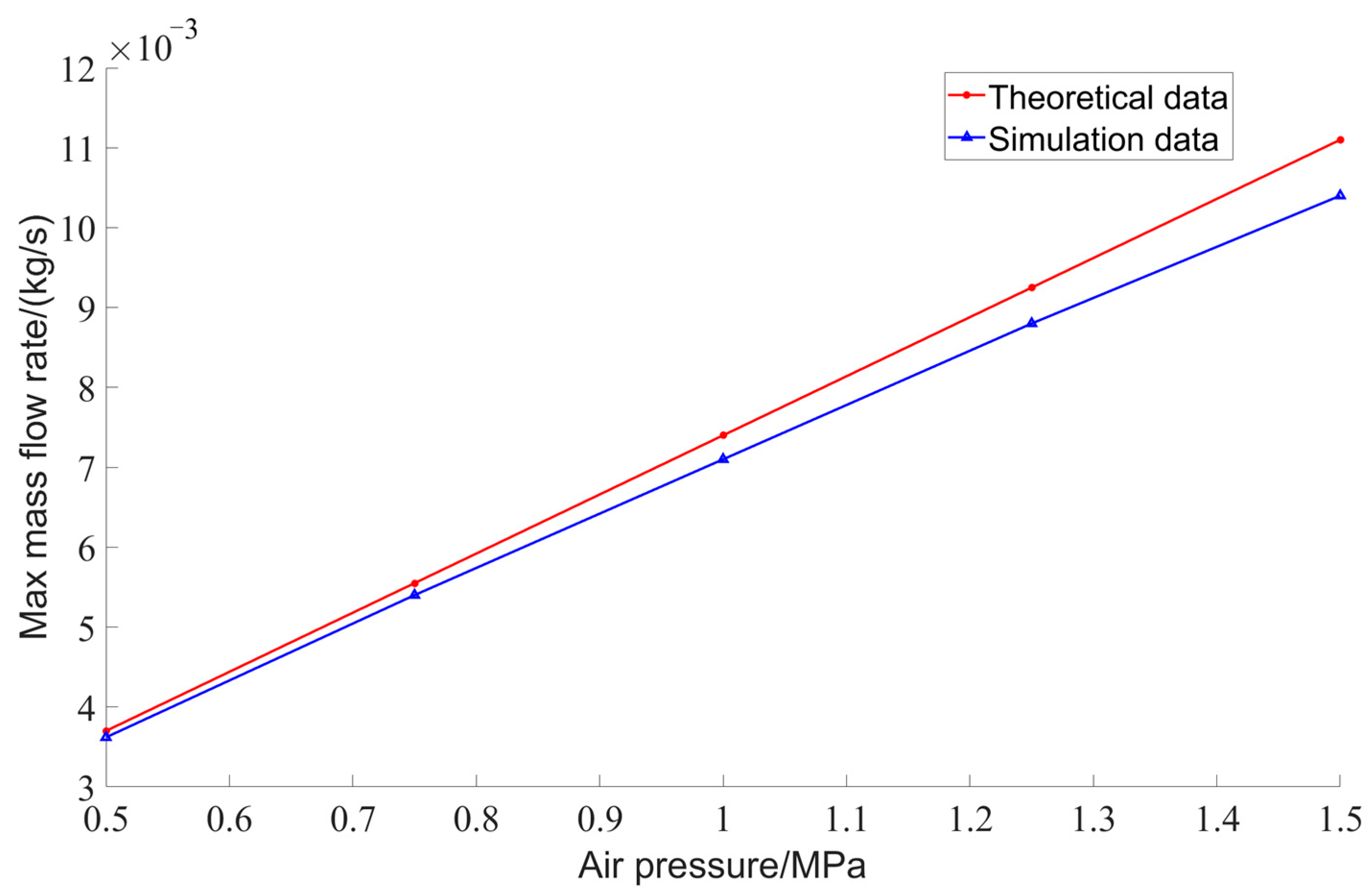
The validation of the computational accuracy of the model involving high-pressure air blowing for ballast tank removal primarily involves comparing the maximum mass flow rate of high-pressure air at the inlet as determined by simulation with the value calculated using the theoretical formula. According to the principles of gas dynamics, the maximum mass flow rate m ˙ max at a high-pressure air inlet can be expressed by the following formula:
m ˙ max = γ R 1 2 2 γ + 1 γ + 1 2 γ 1 P 0 T 0 A *
where γ is the specific heat ratio of the gas, which is 1.4 for air; R is the universal gas constant, 287.1 J/(kg·K); P0 is the total pressure at the nozzle inlet, here referring to the inlet pressure; T0 is the total temperature at the nozzle inlet, set at ambient temperature of 20 °C, equivalent to 293.15 K; A* is the critical cross-sectional area, in this case, the cross-sectional area of the pipeline.
Simulation calculations of the high-pressure air blowing model were performed at high-pressure air inlet pressures of 0.50 MPa, 0.75 MPa, 1.0 MPa, 1.25 MPa, and 1.50 MPa, with a back pressure of 0.06 MPa. The maximum mass flow rates of high-pressure air under various expulsion pressures were obtained. By inserting the radius of the high-pressure air pipeline (0.001 m) and the high-pressure values into Formula (9), theoretical values for the maximum mass flow rate of high-pressure air under each condition were derived. Figure 11 shows the comparison of simulation values versus theoretical values for maximum gas mass flow rates under various conditions, indicating that the errors in simulated values compared to theoretical values are within 6.3%, demonstrating high simulation accuracy of the constructed high-pressure air expulsion model, suitable for further simulation calculations.

5. Simulation Scenarios and Results Analysis

5.1. Scenario Configuration

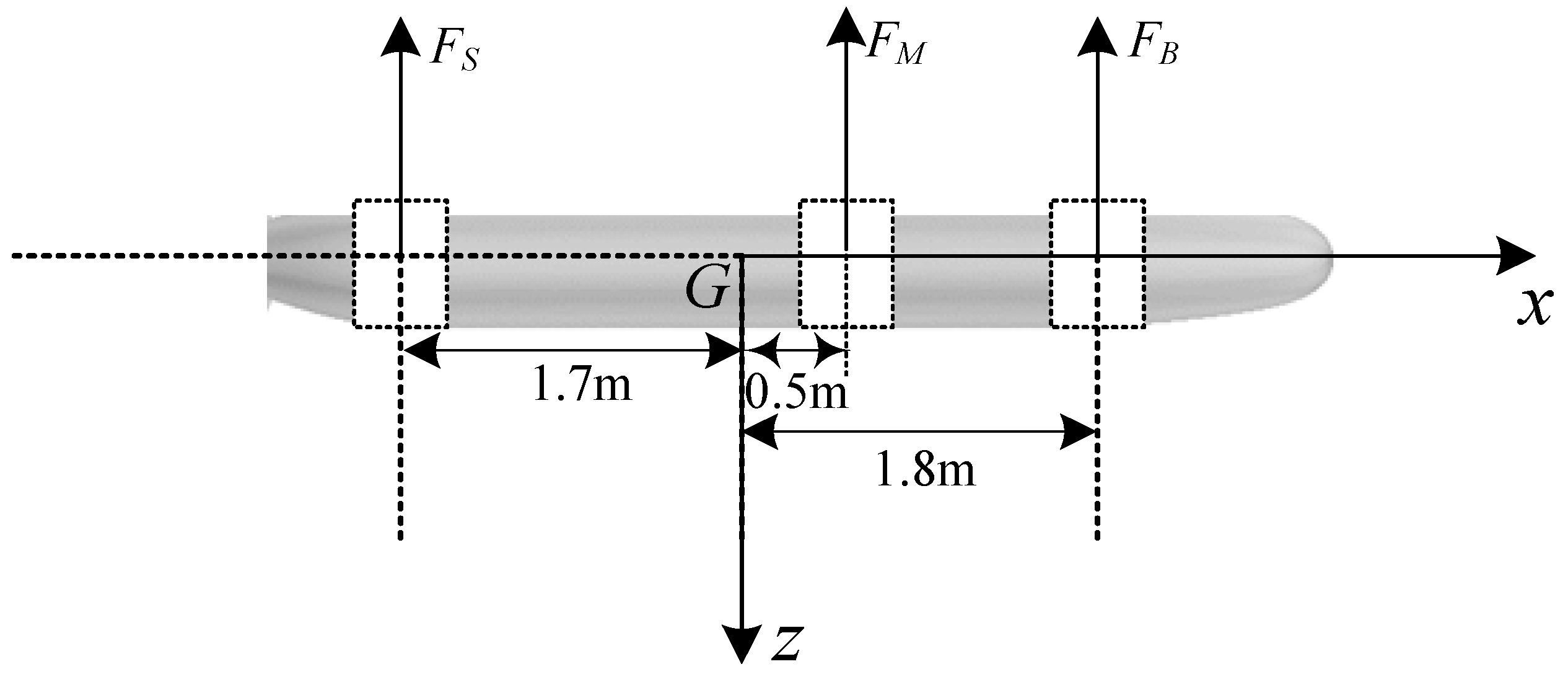
Submarine emergency surfacing is a rapid procedure initiated when a submarine must reach the surface immediately due to a critical situation. At the onset of the surfacing process, the ballast tanks contain water. Injecting air into these tanks expels the water, rapidly generating positive buoyancy and enabling the submarine to surface quickly. These tanks are typically organized into groups, which can be categorized based on their longitudinal placement as fore, mid, and aft groups. As depicted in Figure 12, the center of the foremost group of ballast tanks is situated 1.8 m ahead of the center of gravity. The center of the midship group of ballast tanks is located 0.5 m ahead of the center of gravity, rather than precisely at the center of gravity. The center of the aftermost group of ballast tanks is positioned 1.7 m astern of the center of gravity. The placement of these tank centers is slightly biased towards the bow of the submarine, which helps prevent the development of a bow-up attitude during surfacing. The process of air expulsion from the ballast tanks takes time, gradually reducing the volume of water in the tanks and thereby increasing the upward buoyant force. In this study, air was expelled simultaneously from the fore, mid, and aft group tanks at time zero. Each group of ballast tanks generates a maximum buoyant force of approximately 438 N, totaling 1314 N, which constitutes 19% of the hull’s displacement.
To more closely approximate real-world conditions, the submarine’s emergency surfacing motion should be analyzed through a coupled simulation that incorporates the expulsion of high-pressure air from the ballast tanks. Once the computational accuracy of the simulation model is validated against required standards, the DFBI module can be activated to simulate the submarine’s motion across six degrees of freedom, thereby initiating the simulation of the submarine’s emergency surfacing maneuver. Additionally, the high-pressure air blow-off model can utilize the DFBI module to adjust the ballast tanks’ rotation in real time based on the trim and heel angles provided by the emergency surfacing model.
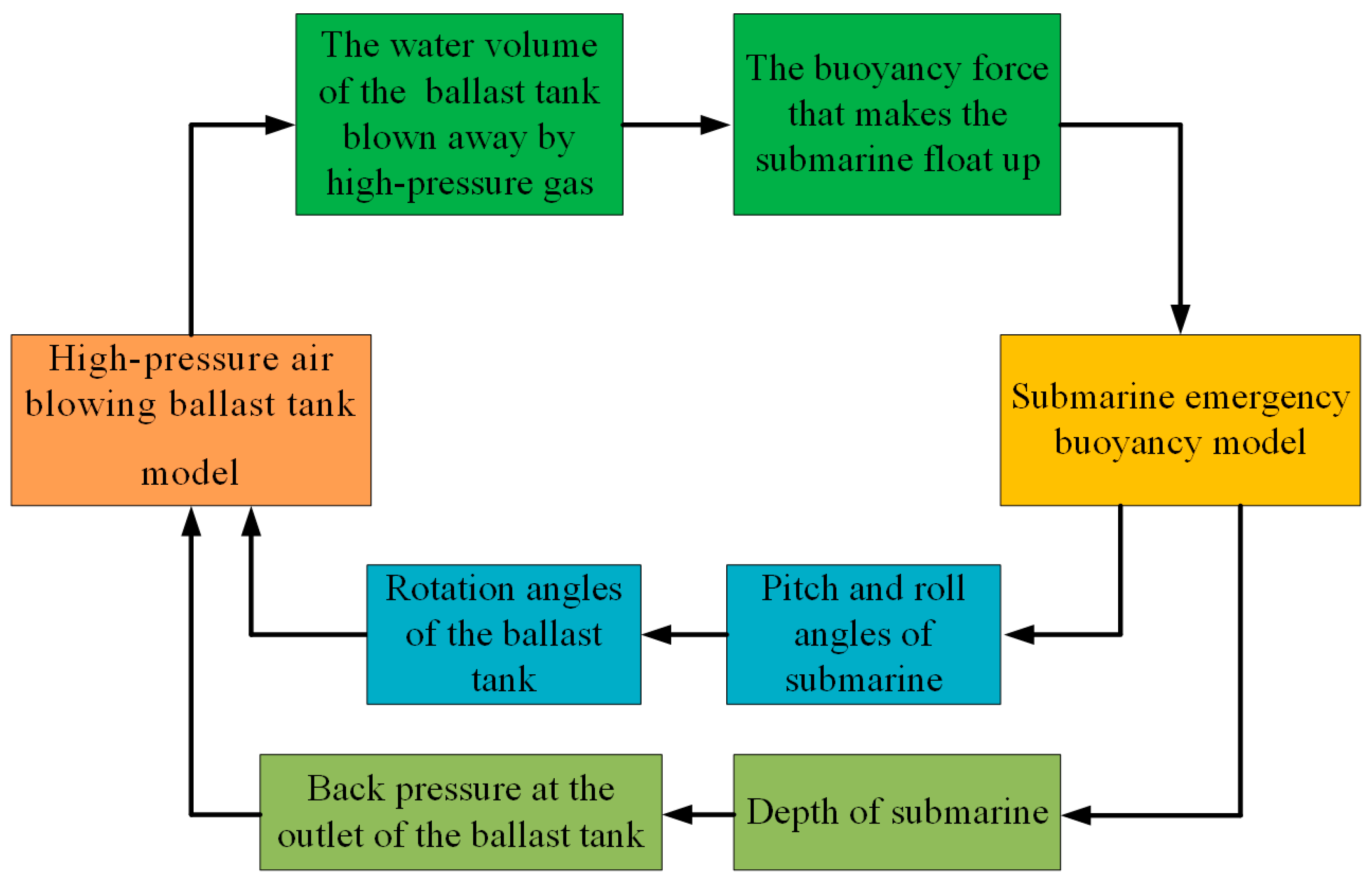
The specific simulation process is depicted in Figure 13. Both the high-pressure air expulsion model and the emergency surfacing motion model are set to the same time step of 0.005 s. At each simulation step, the expulsion model outputs the amount of water expelled, which is then converted into buoyancy and fed into the emergency surfacing model to serve as the submarine’s surfacing buoyancy. Subsequently, at each step, the emergency surfacing model outputs the submarine’s depth, which is fed back to the expulsion model to adjust the back pressure at the outlet. Similarly, the pitch and roll angles are output and fed into the air model, allowing real-time adjustments to the rotation of the ballast tanks during the expulsion process. This iterative cycle allows for real-time data exchange between the two models throughout the simulation, continuing until the end of the 20 s simulation period, ensuring that the results closely mimic the actual conditions of the submarine’s emergency surfacing.
To prevent the propeller from racing during emergency surfacing, submarines typically shut down propulsion. Consequently, this study primarily investigates the dynamics of emergency surfacing at an initial velocity of 1 m/s without propulsion.

5.2. Simulation Results and Analysis of High-Pressure Air Blowing

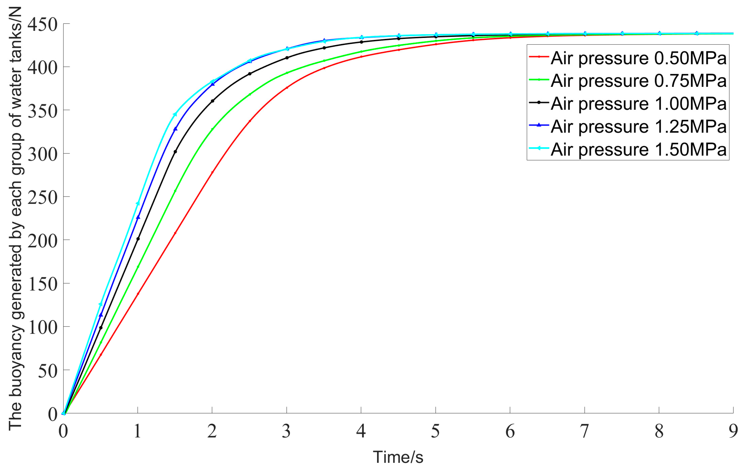
This study investigates the differences in the submarine’s emergency surfacing motion under various pressures during high-pressure air expulsion from the ballast tanks, with pressures set at 0.50 MPa, 0.75 MPa, 1.0 MPa, 1.25 MPa, and 1.50 MPa. Given that the submarine initially submerges at a depth of 6 m, the initial back pressure at the sea hole is 0.06 MPa. With this fixed back pressure of 0.06 MPa, the changes in buoyancy generated by a single group of ballast tanks under different expulsion pressures are depicted in Figure 14. As shown in Figure 14, the buoyancy generated by high-pressure expulsion exhibits a nonlinear variation over time, increasing with greater air pressure settings. While the expulsion rate increases, the speed at which buoyancy is generated also rises; however, the maximum buoyancy generated by a single ballast tank group remains constant. Since water is an incompressible fluid, the introduction of high-pressure air into the ballast tank forces the water to be expelled through the outlet. The higher the pressure of the introduced air, the greater its capacity to force the water out, thereby increasing the flow rate of the water and accelerating the generation of buoyancy. Since the water in the tank will ultimately be completely expelled and the tank has a fixed volume, the maximum buoyancy produced by a single tank remains constant.
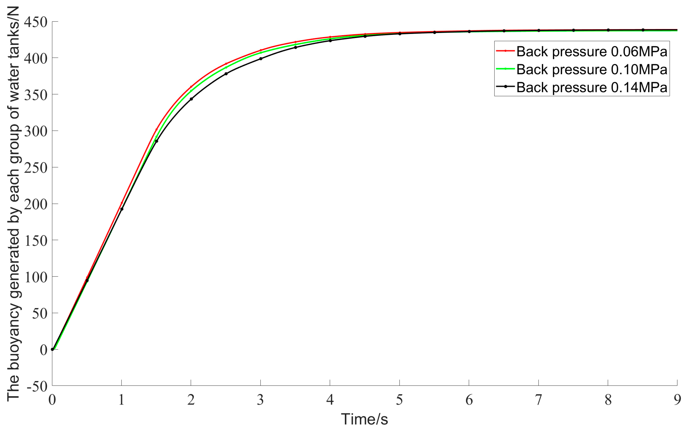
As the submarine ascends and its depth changes, the back pressure at the sea hole also varies. To explore the impact of back pressure on the effectiveness of air expulsion from the ballast tanks, simulation analyses were conducted under varying back pressures at 1.5 MPa of high-pressure air expulsion. As indicated in Figure 15, as the back pressure at the tank outlet increases, the rate of increase in buoyancy gradually slows. Therefore, to more accurately simulate the submarine’s emergency surfacing process, it is essential to consider the variation in back pressure during the air expulsion from the ballast tanks. Since the back pressure at the outlet impedes the flow of water from the ballast tank, the higher the natural back pressure, the slower the water flow rate, and consequently, the slower the increase in buoyancy.
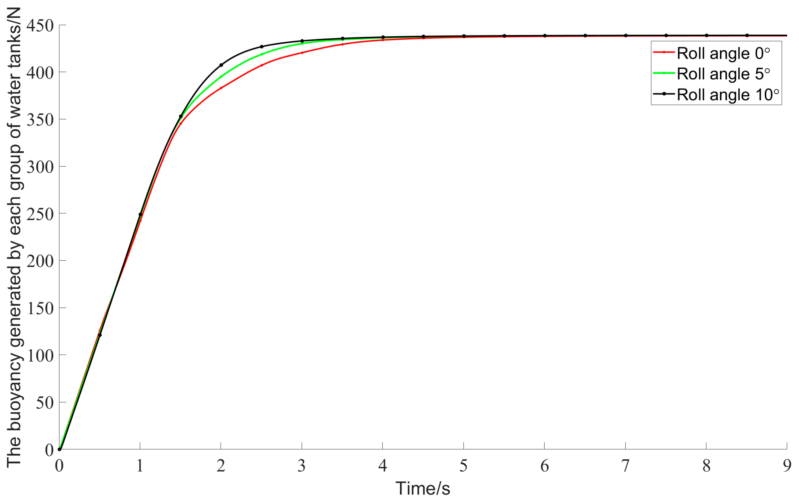
During the surfacing process, the hull of the submarine experiences pitch and roll movements, which can alter the rotational angle of the ballast tanks and potentially affect the effectiveness of the expulsion process. To explore the impact of the submarine’s pitch and roll on the expulsion effectiveness from the ballast tanks, simulation analyses were conducted under different pitch and roll angles using high-pressure air expulsion at 1.5 MPa. Figure 16 and Figure 17 indicate that, while the initial expulsion rates are nearly identical regardless of the tilt angles, the expulsion rate increases significantly between approximately 1.5 s and 4 s. Thus, larger pitch and roll angles correlate with a faster overall expulsion rate. The underlying cause of this phenomenon is that the presence of pitch and roll angles tilts the ballast tank, thereby increasing the area of the free liquid surface within the tank. Under the same pressure, the overall pressure exerted on the water increases due to the enlarged area subjected to force. Consequently, greater pitch and roll angles lead to a more rapid rate of water expulsion from the ballast tank, thereby accelerating the increase in buoyancy.
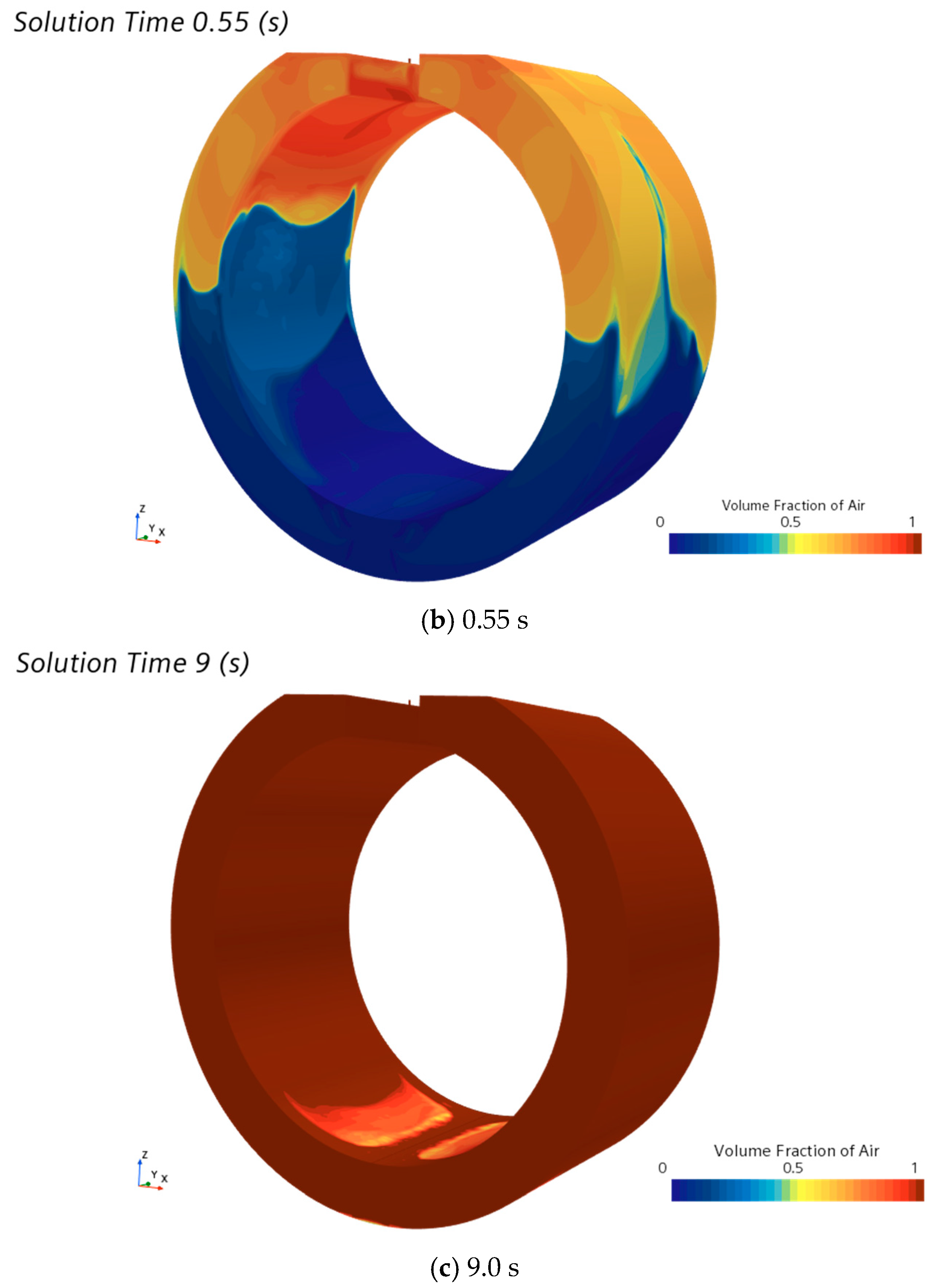
The process of high-pressure air being blown into the water tank allows for an analysis of the distribution and development of each phase throughout the entire flow process. This analysis can be conducted by observing the volume fraction contour maps of the gas and water phases. Figure 18 depicts the distribution of gas and liquid and its evolution in the main ballast tank at various times during the expulsion process, under conditions of an inlet pressure of 1.0 MPa and a back pressure of 0.06 MPa.
Since water is an incompressible fluid, high-pressure air enters the ballast tank through the top inlet, pushing the water out through the sea holes at the bottom under the influence of pressure, gradually increasing the volume of air at the top of the tank. Initially, a vigorous mixing occurs between the strong airflow and the water at the upper part of the tank, creating a gas–liquid mixture near the interface. As the expulsion continues, the volume of water in the ballast tank decreases, and the gas–liquid interface gradually disappears, nearly completing the expulsion of water by 9 s.

5.3. Coupled Simulation Results and Analysis

As discussed in Section 5.2, various factors such as the pressure of high-pressure air, back pressure, and the roll and pitch angles during the surfacing process significantly impact the effectiveness of high-pressure air in clearing the main ballast tanks. This, in turn, influences the emergency surfacing motion of the submarine. Consequently, utilizing the coupled simulation process depicted in Figure 13, we can achieve more realistic outcomes.
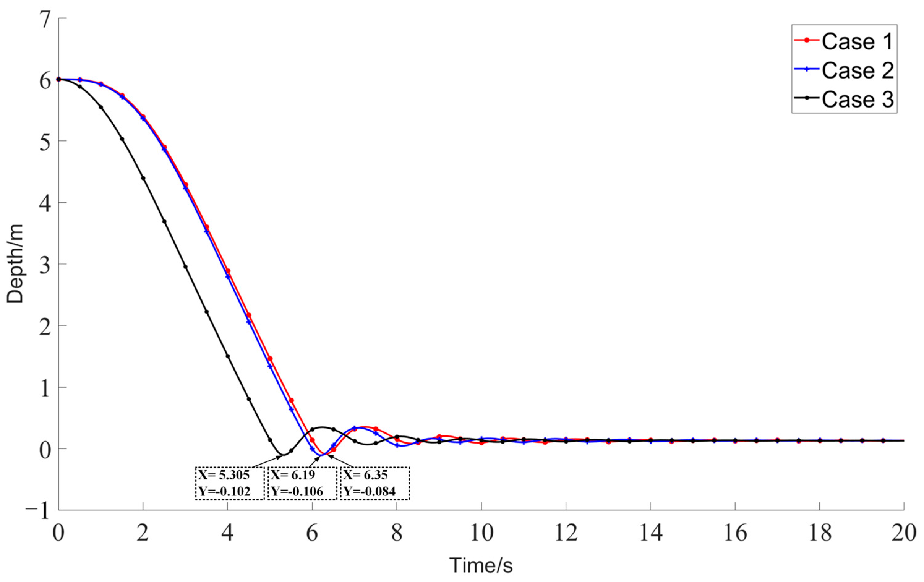
Figure 19 presents the variation in submarine depth over time under various operational conditions with high-pressure air at 1.5 MPa. Specifically, Case 1 represents a scenario where the coupled influences of the two models are not considered, maintaining a fixed back pressure at 0.06 MPa. Here, high-pressure air expulsion from the ballast tanks is the primary input for the buoyancy force driving the submarine’s emergency surfacing. Case 2 illustrates the scenario where the influences of high-pressure air expulsion and the submarine’s emergency surfacing are coupled. In this simulation, key motion parameters such as depth, pitch angle, and roll angle are dynamically integrated through continuous data exchange. Case 3 also disregards the coupled influence of the two factors, similar to Case 1, with a fixed back pressure of 0.06 MPa. In this case, a buoyancy force of 438 N is directly applied at the center of each group of ballast tanks (fore, mid, and aft) at the onset of the simulation.
According to Figure 19, the times to peak water discharge in Cases 1 through 3 are 6.35 s, 6.19 s, and 5.305 s, respectively. Notably, the discharge time for Case 3 is significantly earlier than those for the other cases. This quicker response is due to the immediate application of buoyancy force in Case 3, as opposed to the gradual increase observed in Cases 1 and 2. As a result, the hull in Case 3 surfaces more swiftly. Additionally, Case 2 shows a marginally earlier water discharge time compared to Case 1. Differences are also noted in the heights of the peak water discharge points for each case. This phenomenon can be attributed to the observations from Figure 14, Figure 15 and Figure 16, which show that as the hull ascends, the decreasing depth leads to a reduction in back pressure, and the generation of pitch and roll motions during the ascent. These factors collectively facilitate the expulsion process in the ballast tanks, thereby enabling faster expulsion and quicker ascension of the hull.
For analytical convenience, the overall movement during emergency surfacing can be divided into three phases: underwater ascent, water surface oscillation, and water surface stabilization, as shown in Figure 20, Figure 21 and Figure 22, respectively. Throughout these phases, the submarine experiences a complex interplay of buoyancy from the expulsion in the ballast tanks, static forces, and hydrodynamic effects, demonstrating unstable motions such as pitch, roll, and yaw, characteristic of a six-degree-of-freedom movement.
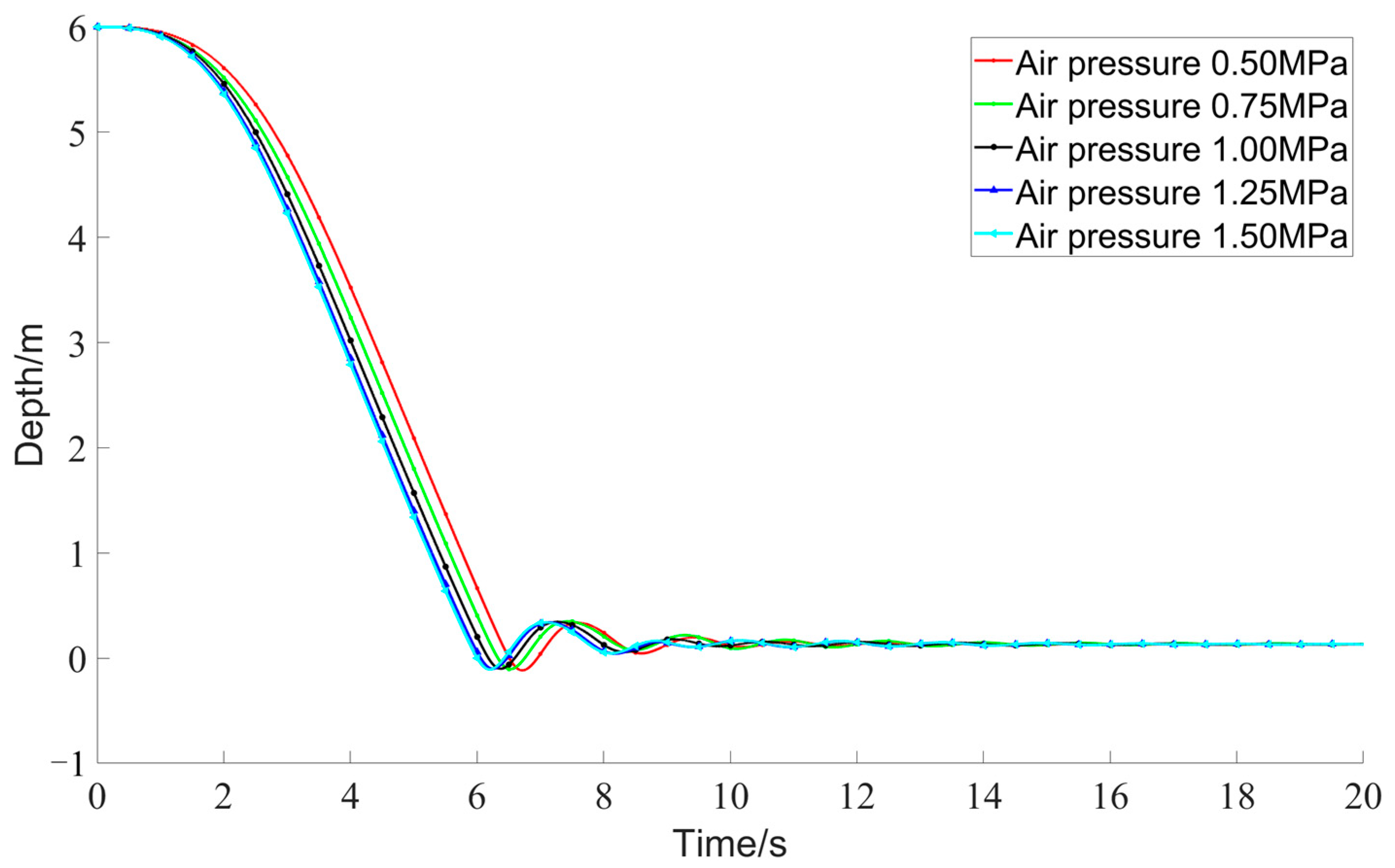
In the context of depth variation, as illustrated in Figure 23, all five operational scenarios undergo a three-stage process: rise from a submerged state at a depth of 6 m to the water surface, and finally stabilization at a consistent surface depth. With the increase in expulsion pressure, the submarine’s emergency surfacing occurs at a higher velocity and the submarine breaches the water surface more promptly. Moreover, as the amplitude of the expulsion pressure increases, the rate of increase in surfacing velocity diminishes, indicating a deceleration in the rate of surfacing velocity increase. Given that the total volume of water expelled and the height of the transverse metacentric center at the water surface remain constant across all scenarios, the duration of surface oscillation and the stable depth at the water surface are approximately the same for each scenario.
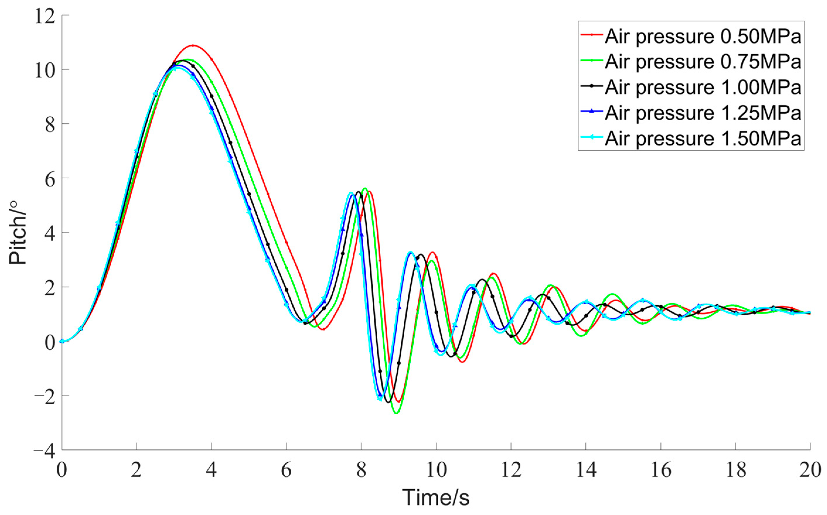
The effect of expulsion pressure on motion stability is primarily manifested in the variations in pitch and roll angles under different conditions. As depicted in Figure 24, for each operational scenario, the hull, under the influence of increasing buoyancy, initially exhibits an increasing stern dip which gradually maximizes before decreasing, and it emerges from the water with a stern dip posture. Following emergence, under the influence of gravity, the hull strikes the water surface, causing the stern dip to increase again until it decreases and transitions to a bow dip. Subsequently, under the effects of inertia, righting moments, and damping moments, the pitch angle continuously oscillates with diminishing amplitude, ultimately stabilizing with a certain stern dip at the water surface.
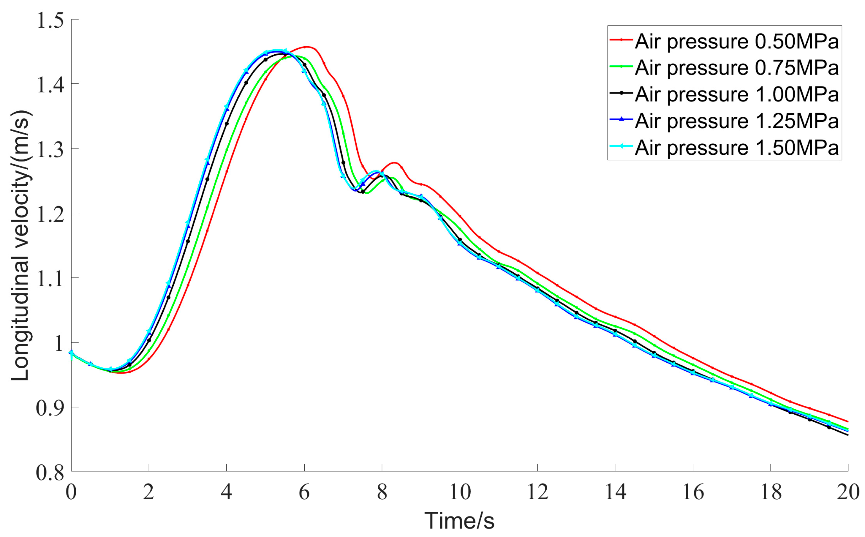
Figure 25 and Figure 26 indicate that during the surfacing phase, as buoyancy increases, for each operational scenario, the longitudinal and vertical velocities of the hull increase, implying greater velocities in the vertical plane. Consequently, the greater the hull’s velocity, the larger the hydrodynamic forces impacting the hull, which generate torque that counteracts the increase in stern dip. Therefore, once the velocity reaches a certain threshold, the hydrodynamic torque of the hull reduces the stern dip, allowing the hull to surface with a minimized stern dip.
By comparing the variations in pitch angles across five operational scenarios, it is clear that higher expulsion pressures result in smaller amplitudes of pitch angles during surfacing, and the transition from stern dip to bow dip occurs earlier. This phenomenon occurs because, as shown in Figure 25 and Figure 26, during the surfacing process, higher expulsion pressures correspond with higher velocities of the hull in the vertical plane, which significantly counteract the increase in stern dip.
Regarding the phenomenon of roll, as depicted in Figure 27, the variation in roll angle under five different conditions during the submarine’s ascent from underwater shows a progressive increase due to the effect of buoyancy. As the submarine transitions from submerged to the water surface, the hull’s exposure above the water increases due to inertia, resulting in a reduction in stability and a significant increase in roll during this phase. Following the emergence from the water, under the influence of the righting moment, the roll angle oscillates for a period before gradually exhibiting a trend of periodic decrease.
Comparative analysis of the roll angle under five operational conditions reveals that a higher expulsion pressure results in greater amplitude of roll during the ascent phase, with peak values appearing earlier. This is attributed to lateral forces acting on the submarine, particularly the lateral forces impacting the conning tower enclosure, generating a heeling moment and consequently inducing roll. Higher expulsion pressures accelerate the submarine’s ascent, increasing the lateral forces and thereby resulting in greater roll. During the surface oscillation phase, the amplitude of roll does not follow a clear pattern with changes in expulsion pressure.
Comparison of yaw angle changes under five conditions shows that increasing expulsion pressure does not result in a clear pattern in yaw angle, as depicted in Figure 28. This is due to the randomness inherent in the yaw of torpedo-shaped submarines during propulsion. However, the variation in yaw angle provides some explanation for the lack of a clear pattern in roll amplitude with changes in expulsion pressure during the surface oscillation phase. For instance, in the condition with an expulsion pressure of 1.00 MPa, a rapid increase in yaw angle after 14 s leads to a sudden increase in lateral forces impacting the hull, resulting in a rise rather than a decrease in roll angle amplitude after 14 s. This indicates that changes in yaw angle significantly influence the variation in roll angle.

6. Discussion and Conclusions

This study utilized the STAR CCM+(20.02.007) simulation software, employing whole moving mesh technology, to develop simulation models for both the standard submarine model Suboff and the interstitial ballast tanks. These models focused on the dynamics of emergency surfacing and high-pressure air expulsion from the ballast tanks. Given the mutual influence of these two processes during simulation, a data interface was established between the models to enable real-time interaction of parameters such as depth, pitch angle, and roll angle, thereby enhancing the realism of the simulation process. On the basis of constructing this coupled analysis model, this study investigated the effects of different expulsion pressures on submarine motion parameters such as depth, roll, pitch, and yaw angles, yielding the following conclusions:
  • The hull emerges slightly earlier and reaches a marginally higher point when coupling effects are accounted for compared to scenarios where these effects are neglected.
  • At constant expulsion pressures, larger pitch and roll angles, coupled with lower back pressures, accelerate the expulsion rate from the ballast tanks.
  • Higher expulsion pressures facilitate quicker surfacing of the hull, reduce the amplitude of pitch angles, and increase the amplitude of roll angles.
The methodologies and findings of this research provide significant guidance for the design of high-pressure air systems and the operational maneuvers for emergency surfacing of submarines. However, the current lack of facilities to conduct submarine emergency surfacing experiments within this study’s scope means that the validation of the experimental outcomes has primarily relied on hydrodynamic data associated with various angles of attack, as reported in existing literature. Although this approach has effectively confirmed the accuracy of the simulation results obtained in this study, it carries certain inherent limitations. In response to this issue, the research team is now developing a self-propelled submarine model equipped with ballast tanks. Upon completing this construction phase, we will initiate experiments focused on the emergency surfacing motion of the model. The data from these experiments will be crucial for directly validating the simulation’s precision, thus enabling further improvements in simulation accuracy.

Author Contributions

Conceptualization, J.C.; methodology, J.C.; software, J.C.; resources, B.L.; data curation, B.L.; writing—original draft preparation, J.C.; writing—review and editing, L.P. and B.L.; supervision, W.P. and Y.W. All authors have read and agreed to the published version of the manuscript.

Funding

This research received no external funding.

Data Availability Statement

The data presented in this study are available on request from the corresponding author. The data are not publicly available due to privacy or ethical restrictions.

Conflicts of Interest

The authors declare no conflicts of interest.

References

  1. Pan, W.; Wang, Y.; Song, F.; Peng, L.; Zhang, X. UUV-Assisted Icebreaking Application in Polar Environments Using GA-SPSO. J. Mar. Sci. Eng. 2024, 12, 1845. [Google Scholar] [CrossRef]
  2. Lin, Y.-H.; Tseng, S.-H.; Chen, Y.-H. The experimental study on maneuvering derivatives of a submerged body SUBOFF by implementing the Planar Motion Mechanism tests. Ocean Eng. 2018, 170, 120–135. [Google Scholar] [CrossRef]
  3. Xiang, G.; Ou, Y.; Chen, J.; Wang, W.; Wu, H. Identification of Hydrodynamic Coefficients of the SUBOFF Submarine Using the Bayesian Ridge Regression Model. Appl. Sci. 2023, 13, 12342. [Google Scholar] [CrossRef]
  4. Park, J.-Y.; Kim, N.; Shin, Y.-K. Experimental study on hydrodynamic coefficients for high-incidence-angle maneuver of a submarine. Int. J. Nav. Archit. Ocean Eng. 2016, 8, 735–754. [Google Scholar] [CrossRef]
  5. Kim, D.J.; Kwon, C.S.; Lee, Y.Y.; Kim, Y.G.; Yun, K. Practical 6-dof manoeuvring simulation of a bb2 submarine near the free surface. Ocean Eng. 2024, 312, 23. [Google Scholar] [CrossRef]
  6. Watson, K.P.; Webster, J.S. Prediction of submersible maneuvering performance at high incidence angles. In Proceedings of the OCEANS’93, Victoria, BC, Canada, 18–21 October 1993; pp. 289–294. [Google Scholar]
  7. Font, R.; García-Peláez, J.; Murillo, J.A.; Periago, F. Modelling and control of blowing-venting operations in manned submarines. Ocean Eng. 2011, 38, 1627–1636. [Google Scholar]
  8. Gertler, M.; Hagen, G.R. Standard Equations of Motion for Submarine Simulation, NSRDC Report 2510. Available online: https://apps.dtic.mil/sti/pdfs/AD0653861.pdf (accessed on 25 November 2020).
  9. Liu, R.; Xiao, C.; Liu, Y. The experiment research of high-pressure air blowing ballast tanks. Appl. Mech. Mater. 2013, 411, 3010–3015. [Google Scholar] [CrossRef]
  10. Zhang, S.; Li, H.; Pang, Y.; Chen, Q.; Yan, P. Experimental investigation on roll stability of blunt-nose submarine in buoyantly rising maneuvers. Appl. Ocean Res. 2018, 81, 34–46. [Google Scholar] [CrossRef]
  11. Jung, J.S.; Lee, S.W.; Shin, J.H. A Model Experimental Study on Water flows out from the Ballast Tank for Emergency Rising of Submarines. J. Ocean Eng. Technol. 2024, 38, 370–383. [Google Scholar] [CrossRef]
  12. Wang, Z.; Dong, Z.; He, R.; Wang, X. Numerical simulation of submarine surfacing with 6 DOF model in the ocean current effect. In Proceedings of the 12th Pacific-Asia Offshore Mechanics Symposium, Gold Coast, Australia, 4–7 October 2016; pp. 137–143. [Google Scholar]
  13. Zhang, Z.; Guo, L.; Wei, P.; Wang, X.; Feng, D. Numerical simulation of submarine surfacing motion in regular waves. Iran. J. Sci. Technol. Trans. Mech. Eng. 2018, 44, 359–372. [Google Scholar] [CrossRef]
  14. Chen, Q.; Li, H.; Pang, Y.; Zhang, S.; Chang, W. Investigation of the excess roll problem of an emergent buoyantly rising submarine. J. Fluids Struct. 2019, 91, 102720. [Google Scholar] [CrossRef]
  15. Chen, Q.; Li, H.; Zhang, S.; Wang, J.; Pang, Y. Effect of waves on the behavior of emergent buoyantly rising submarines using CFD. Appl. Sci. 2020, 10, 8403. [Google Scholar] [CrossRef]
  16. Zhang, S.; Li, H.; Zhang, T.; Pang, Y.; Chen, Q. Numerical simulation study on the effects of course keeping on the roll stability of submarine emergency rising. Appl. Sci. 2019, 9, 3285. [Google Scholar] [CrossRef]
  17. Wei, K.; Gao, X.; Liu, D.; Wei, F.; Luo, P. Numerical calculation of six degree of freedom floating motion of submarine with flow holes. J. Mar. Sci. Technol. 2022, 27, 916–934. [Google Scholar] [CrossRef]
  18. Wei, K.; Gao, X.; Liu, D.; Wei, F.; Luo, P. Research on the submarine floating movement in waves involving the water holes. Ocean Eng. 2023, 272, 111326. [Google Scholar] [CrossRef]
  19. Guo, X.; Ou, Y.; Chen, J.; Wang, W.; Wu, H. A study on the influence of unsteady forces on the roll characteristics of a submarine during free ascent from great depth. J. Mar. Sci. Eng. 2024, 12, 757. [Google Scholar] [CrossRef]
  20. Xiang, G.; Ou, Y.; Chen, J.; Wang, W.; Wu, H. Numerical Study on the Flow Characteristics of High Attack Angle around the Submarine’s Vertical Plane. Appl. Sci. 2024, 14, 395. [Google Scholar] [CrossRef]
  21. Chen, X.; Yao, J. Rans analysis of manoeuvring hydrodynamic performance for a submarine in six degree of freedom motion. Ocean Eng. 2024, 294, 116781. [Google Scholar] [CrossRef]
  22. Lin, Y.; Li, X. The investigation of a sliding mesh model for hydrodynamic analysis of a suboff model in turbulent flow fields. J. Mar. Sci. Eng. 2020, 8, 744. [Google Scholar] [CrossRef]
  23. ITTC. ITTC—Recommended Procedures and Guidelines 7.5-03-01-04 CFD. In General CFD Verification; ITTC: Singapore, 2011. [Google Scholar]
  24. Roddy, R.F. Investigation of the stability and control characteristics of several configurations of the DARPA Suboff model (DTRC Model 5470) from captive-model experiments. In David Taylor Research Center Report; Ship Hydromechanics Dept, David Taylor Research Center: Bethesda, MD, USA, 1990. [Google Scholar]
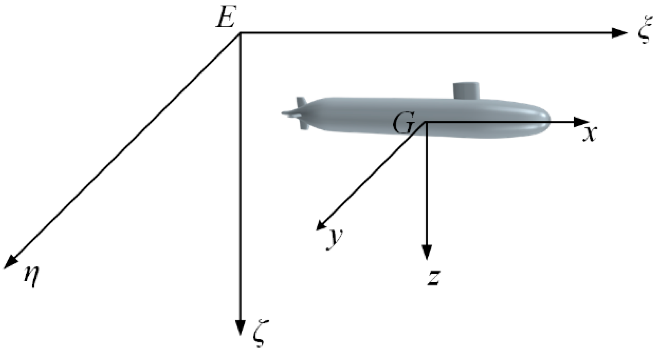
Figure 1. Suboff geometric model and coordinate system.
Jmse 13 01769 g001
Figure 2. Geometric model of the ballast tank.
Jmse 13 01769 g002
Figure 3. Computational domain dimensions and boundary conditions.
Jmse 13 01769 g003
Figure 4. Mesh partitioning for ballast tanks between hulls.
Jmse 13 01769 g004
Figure 5. Overall spatial mesh discretization.
Jmse 13 01769 g005
Figure 6. Free surface mesh refinement.
Jmse 13 01769 g006
Figure 7. Variation of the longitudinal force coefficient with mesh count.
Jmse 13 01769 g007
Figure 8. Variation curve of expelled water volume from ballast tank with mesh quantity.
Jmse 13 01769 g008
Figure 9. Comparison curve of vertical force coefficient simulation values and experimental values.
Jmse 13 01769 g009
Figure 10. Comparison curve of pitching moment coefficient simulation values and experimental values.
Jmse 13 01769 g010
Figure 11. Comparison curve of the theoretical and simulated maximum gas mass flow rates.
Jmse 13 01769 g011
Figure 12. Schematic of the ballast tank arrangement and buoyancy application points.
Jmse 13 01769 g012
Figure 13. Coupled simulation flowchart of the high-pressure air expulsion model and the emergency surfacing model.
Jmse 13 01769 g013
Figure 14. Changes in buoyancy generated by a single ballast tank group under different expulsion pressures.
Jmse 13 01769 g014
Figure 15. Changes in buoyancy under different back pressures in a single ballast tank group.
Jmse 13 01769 g015
Figure 16. Changes in buoyancy generated by a single ballast tank under different pitch angles.
Jmse 13 01769 g016
Figure 17. Changes in buoyancy generated by a single ballast tank under different roll angles.
Jmse 13 01769 g017
Figure 18. Ballast tank water levels at various expulsion times.
Jmse 13 01769 g018aJmse 13 01769 g018b
Figure 19. Variation in hull depth over time under different operating conditions.
Jmse 13 01769 g019
Figure 20. The dynamic state of the submarine during the underwater ascent phase (t = 3.0 s).
Jmse 13 01769 g020
Figure 21. The dynamic state of the submarine during the water surface oscillation phase (t = 5.85 s).
Jmse 13 01769 g021
Figure 22. The dynamic state of the submarine during the water surface stabilization phase (t = 10.15 s).
Jmse 13 01769 g022
Figure 23. Depth variations under different expulsion pressures.
Jmse 13 01769 g023
Figure 24. Variations in pitch angle under different expulsion pressures.
Jmse 13 01769 g024
Figure 25. Longitudinal velocity variations under different expulsion pressures.
Jmse 13 01769 g025
Figure 26. Vertical velocity variations under different expulsion pressures.
Jmse 13 01769 g026
Figure 27. Variation in roll angle under different expulsion pressures.
Jmse 13 01769 g027
Figure 28. Variation in yaw angle under different expulsion pressures.
Jmse 13 01769 g028
Table 1. Main parameters of the Suboff model.
ParametersValue
Length L (m)4.356
Beam B (m)0.508
Submerged Displacement Mass M (kg)704 kg
Center of Gravity Position (m)(2.002, 0.0, 0.02)
Moment of Inertia (kg·m−2)(27.65, 834.15, 834.15)
Table 2. Mesh sizes and quantities.
Submarine emergency buoyancy modelMesh size/m0.1410.10.070.050.035
Mesh quantity/10425.450.9104.1154.4570.8
High-pressure air blowing ballast tank modelMesh size/m0.0040.00280.0020.00140.001
Mesh quantity/10419.252.2148.6318.1973.1
Table 3. Vertical force coefficient simulation values and experimental values.
Attack Angle (°) Z Sim  (10−3) Z Exp  (10−3)Relative Error
20.34220.32375.7%
40.89070.9034−1.4%
61.5451.612−4.2%
82.5562.5251.2%
103.6443.856−5.5%
124.9495.205−4.9%
146.4276.829−5.9%
167.9058.486−6.8%
189.64510.25−5.9%
Table 4. Pitching moment coefficient simulation values and experimental values.
Attack Angle (°) M Sim  (10−3) M Exp  (10−3)Relative Error
20.44240.4761−7.1%
40.79080.8326−5.0%
61.1101.1050.5%
81.3411.3152.0%
101.4911.4622.0%
121.5851.5432.7%
141.6891.6214.2%
161.8071.7046.1%
181.9091.7628.3%
Disclaimer/Publisher’s Note: The statements, opinions and data contained in all publications are solely those of the individual author(s) and contributor(s) and not of MDPI and/or the editor(s). MDPI and/or the editor(s) disclaim responsibility for any injury to people or property resulting from any ideas, methods, instructions or products referred to in the content.