1. Introduction
Wave energy converters (WECs) that utilize winch-based, single-point mooring systems present unique challenges for mooring line design and system dynamics. As these WECs respond to wave-induced heave and surge motions, they generate mechanical shaft power by tensioning a mooring line anchored to the seabed, which in turn drives a power take-off (PTO) to produce electrical or hydraulic energy. However, the use of a single mooring attachment leaves the WEC’s sway, roll, and yaw motions unconstrained, introducing complex off-axis loads and potential twisting in the mooring line. The National Renewable Energy Laboratory’s (NREL’s) hydraulic and electric reverse osmosis (HERO) WEC (NREL, Golden, CO, USA) [
1] exemplifies this class of devices and serves as a modular test bed to explore these challenges. The HERO WEC uses a winch-driven rotary drivetrain to convert energy through either a hydraulic configuration or an electrical configuration. In its hydraulic configuration, the HERO WEC pumps seawater to shore via a hose to drive a reverse osmosis desalination system. In its electric configuration, an onboard generator supplies alternating current (AC) electrical power through a subsea cable, which is converted to direct current (DC) power onshore to power submersible pumps for the same purpose. By examining the HERO WEC, researchers can better understand the coupled dynamics of winch-based WECs and their implications for mooring design, drivetrain reliability, and offshore desalination performance.
Stainless steel wire ropes have been used as mooring lines in this application because they are capable of withstanding high tensile loads; however, their cross-sectional profile makes them prone to bending fatigue in systems with small-diameter pulleys and frequent cycling, requiring frequent replacement. Bending fatigue is driven by the stresses induced on the wire rope as it passes over a pulley with a tension load applied. The maximum stress in the wire rope under this load case occurs at the surface of the wire rope farthest from its neutral axis. This is because the magnitude of bending stress is known to increase with distance from the neutral axis of an object in bending [
2]. For wire ropes of the same construction, the tensile working load increases with diameter due to the stress reduction that results from an increase in the cross-sectional metallic area [
3] (p. 102). However, the fatigue life in bending over a pulley of a given radius decreases as the diameter of the wire rope is increased [
4,
5]. In the design of winch-driven WECs, mooring lines must be carefully selected to ensure an adequate working load and long bending fatigue life over pulleys that are small enough to fit within the design constraints of the WEC. Mooring lines are also subjected to bending cycles as they coil onto or uncoil off a winch drum. The winch drum’s interactions with the mooring line and drivetrain present a design challenge, because the bending radius here varies depending on the diameter of the mooring line and number of coils on the drum. As the bending radius of the mooring line varies, the length of the moment arm at which tension is applied to the winch drum also varies, resulting in differences in drivetrain torque and speed throughout the WEC’s range of travel. Due to these operational variations, the diameter of wire rope used as a mooring line must be carefully selected to balance fatigue life, working load, and drivetrain performance.
The bending stresses and fatigue life of wire ropes in applications like the HERO WEC can be predicted using well-established equations for bending fatigue, such as those proposed by the American Steel & Wire Company [
4] (pp. 29–66), Shigley [
5] (pp. 908–914) and Feyrer [
6]. These methods can account for factors such as side deflection, multilayer wrapping, and environmental impacts. One key term in both sets of equations is the ratio of the diameter of the pulley that the wire rope bends over to the diameter of the wire rope. This ratio has been found to be one of the dominant factors in wire rope fatigue, and the fatigue life of a wire rope is known to increase exponentially with this ratio. These equations are used to calculate the number of simple bending cycles at a particular load state, which will result in failure of a wire rope in bending fatigue. For an element along the length of the wire rope, a simple bending cycle occurs when the element bends and unbends under a uniform load. This cycle typically occurs when the element runs onto a pulley, bending and running over an arc on the pulley’s face, then unbending and continuing to run straight. Alternatively, a simple bending cycle can occur as an element unbends and runs off a pulley, then bends in the same direction as it runs onto the next pulley. A diagram of mooring line bending cycles on the HERO WEC is provided in
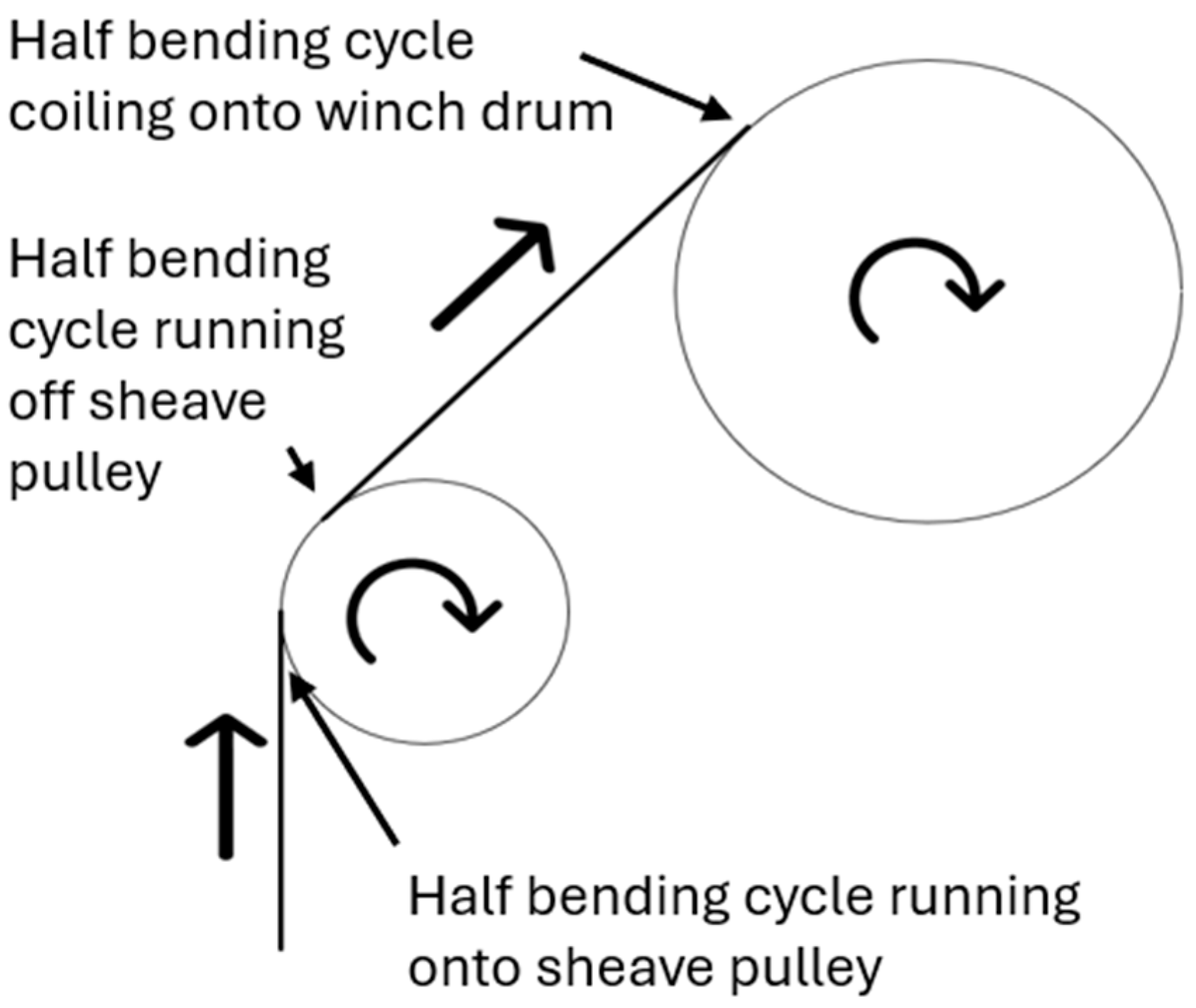
Figure 1.
The mooring line is subjected to a full bending cycle as it runs onto and then off of the sheave pulley and a half bending cycle as it coils on the winch drum. During normal operation of the HERO WEC, the mooring line is coiled on a multilayer winch drum with approximately 180 N of tension and uncoiled with up to 10,000 N of tension as the WEC moves in surge and heave with each wave. This motion is rectified using a one-way clutch located inside the winch drum that spins the WEC’s drivetrain, supplying rotational power to either the hydraulic pump or electric generator. In previous deployments and lab testing, the HERO WEC has used a 7 × 19 strand, 7.94 mm (5/16 inch) diameter stainless steel wire rope with a working load of 6700 N. It should be noted that during testing the WEC experienced events with peak tensions above the 6700 N working load of this wire rope, reducing the overall fatigue life. Each wave cycle consists of the mooring line uncoiling from the winch drum under a tension force of up to 10,000 N, depending on wave conditions, and then coiling on the winch drum under a tension force of approximately 180 N. For the most frequently stressed section of the wire rope, each load cycle can include up to three individual bending cycles consisting of a half bending cycle uncoiling from the 216 mm effective diameter of the winch drum and a full bending cycle over the 159 mm diameter sheave pulley under tension loads up to 10,000 N as the WEC moves away from its anchor. Another full bending cycle occurs over the sheave pulley, and a half bending cycle occurs over the drum under a tension load of approximately 180 N as the stored energy in the spring return is used to move the WEC closer to its anchor. The exact number of bending cycles contained in a load cycle for an element along the length of the wire rope depends on the magnitude of the WEC’s displacement relative to its anchor during the time that it is affected by a single wave.
During a previous test program in 2023 [
7] using NREL’s Large Amplitude Motion Platform (LAMP; NREL, Flatirons Campus, Arvada, CO, USA) [
8]—a six-degree-of-freedom motion platform manufactured by E2M Technologies (Amsterdam, Netherlands) that has been adapted for testing WECs—a wire rope mooring line was subjected to 13,896 load cycles of up to 10,000 N and showed signs of fatigue and abrasion damage. These signs were visible in the form of broken wires at the surface of the most cycled portion of the wire rope as described in Feyrer 2007 [
6]. During its 2024 hydraulic configuration ocean deployment [
9], the HERO WEC’s mooring line was subjected to more than 52,000
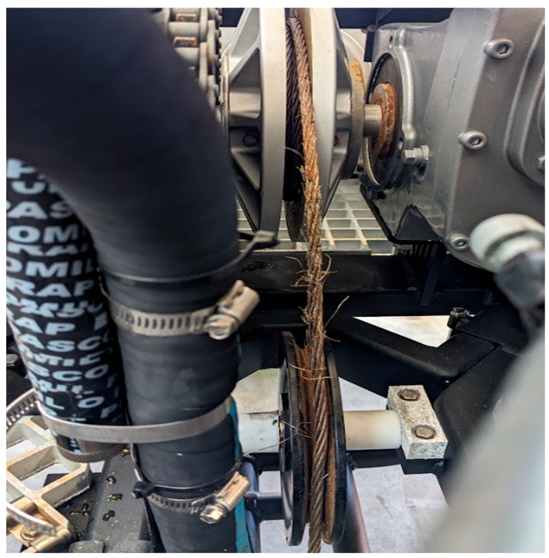
1 load cycles of up to 7500 N and showed similar signs of fatigue damage and abrasion in the form of broken and kinked wires, along with significant corrosion in the region that ran over the sheave pulley (
Figure 2).
To improve the service life of the HERO WEC system, polyurethane flat belts have been proposed as an alternative to stainless steel wire ropes. These belts are constructed from multiple small-diameter wire rope tension members encased in a polyurethane sheath. Due to the belt’s thin side profile and therefore the proximity of the outside surface of each wire rope to its neutral axis, the tension members of flat belts are expected to experience significantly lower bending stresses [
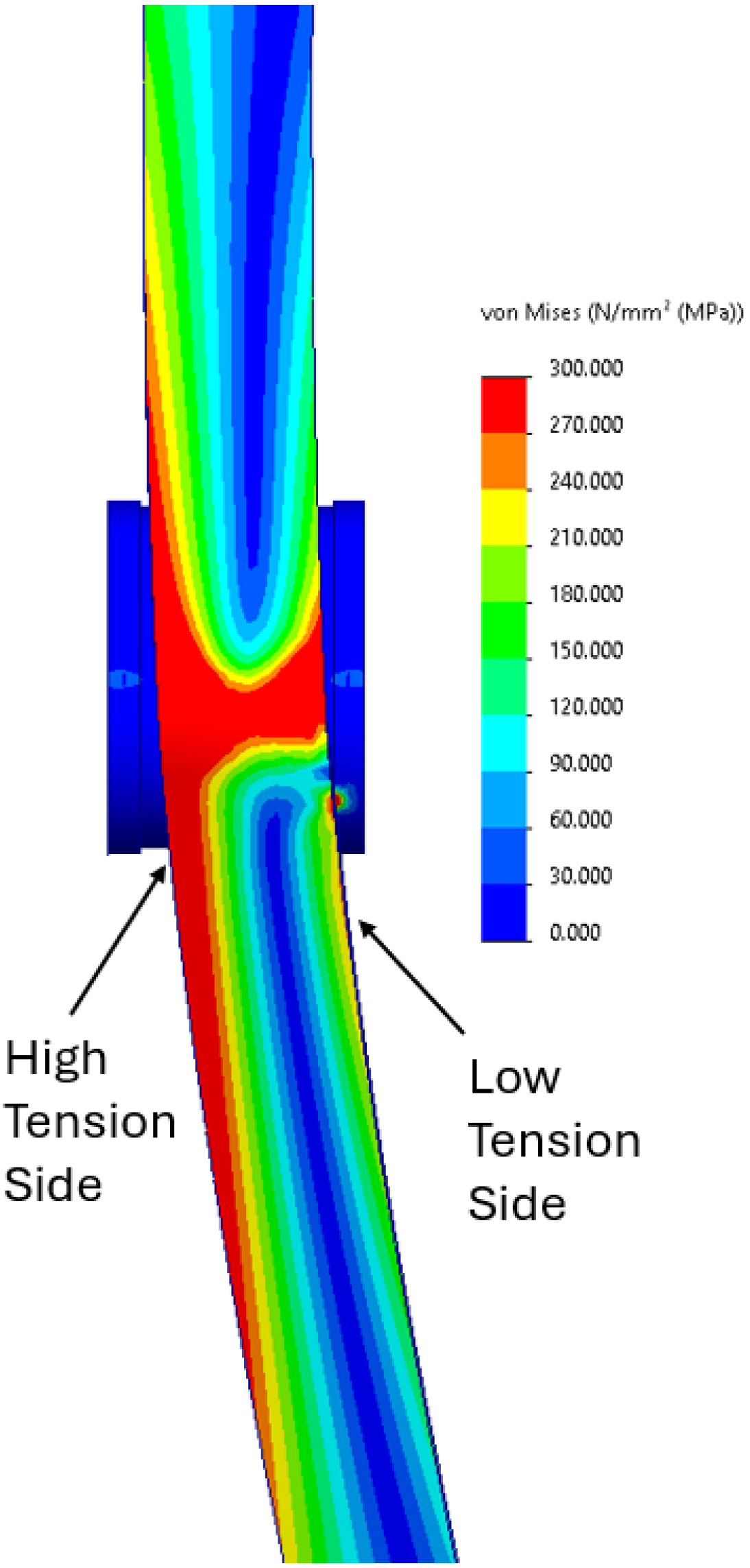
2], resulting in a longer fatigue life compared to traditional wire ropes. Because of their thin design, flat belts also offer the potential for more consistent effective drum diameters and rotational velocities across the WEC’s range of travel. Additionally, the small bending radius requirements and small thickness of polyurethane flat belts present an opportunity to design a more compact winch for a given line capacity. While polyurethane flat belts are expected to offer an improved bending fatigue life over traditional wire ropes, concerns exist about the performance of flat belts under the unconventional load conditions which occur in marine energy applications, such as twisting, off-axis loading, abrasion, and uneven coiling and payout tensions. Off-axis loading is expected to cause an uneven stress distribution in the contact patch on pulleys and the surrounding region. Finite element analysis in SolidWorks 2023 was used to approximate the expected stress distribution in the belt in both cases (
Figure 3). An assembly consisting of a 159 mm diameter aluminum pulley and a representative belt component was modeled with the homogenized polyurethane material properties used by Abdellatef et al. [
10]. In this study, the belt had a 30-degree contact arc on the pulley. The top end of the belt was fixed, and a tension force of 11,120 N (2500 lbf) was applied at the bottom end of the belt. A prescribed displacement was also applied at this location. The off-axis load case was found to result in an uneven stress distribution, showing higher tensions on the side of the belt opposite to the direction of the applied displacement at the load end. Smaller stress concentrations were observed on the opposite edge of the belt. Displacement of the belt resulting in contact with the flange along the low-tension side at the load side edge of the contact patch was found to be at least partly responsible for these stress concentrations.
Previous research into the use of flat belts in marine energy applications is limited, with only a few studies addressing their performance across a small number of wave energy converters in very specific test applications, which do not include multi-layer winch driven systems [
10,
11,
12,
13]. Some additional studies have been conducted on synthetic mooring ropes in marine renewable energy applications such as the study by Weller et al. [
14], although the results from these studies are not directly applicable to the polyurethane flat belts evaluated in this study. Thies et al. [
15] evaluated the use of HDPE belts in marine energy mooring applications. Abdellatef et al. [
10] studied the fatigue and wear of a polyurethane flat belt using a test stand to simulate load cases that it would be subjected to by a point-absorber WEC. This test stands subjected two polyurethane flat belts to identical tension and motion profiles with an adjustable pulley axis that was used to create a fleet angle ranging from 0 to 3 degrees on one of these belts. In their test, the tensioned belts were driven by an electric motor and drive pulley assembly, producing a shear load in the belt that was subjected to various fleet angles. Their study subjected both belts to 847,612 bending cycles and found that wear of the polyurethane caused by the uneven belt-to-pulley contact when fleet angles are present may limit the lifespan of a polyurethane flat belt in marine energy applications. Additionally, larger fleet angles were found to create stability issues in the belt at its contact location with the pulley. In marine energy applications, mooring lines may be subjected to adhesion and abrasion wear as they slide across pulleys. These types of wear are well understood, and wear volume of the softer component involved in this interaction can be modeled using the Archard wear law [
16] (p. 235). The Archard law states that wear volume is directly proportional to the distance a component slides against another component, highlighting the need to quantify the amount of slip that occurs between layers of the mooring line on the winch drum as a result of uneven coiling and uncoiling tensions in this application.
The purpose of this study is to evaluate the suitability of polyurethane flat belts for marine energy applications, particularly as a replacement for wire rope mooring lines in point-absorber-type WEC systems that are driven by a winch and have a single mooring. This study focuses on the ability of the belts to withstand the unique load cases experienced in this application, including twisting, off-axis loading, uneven loading, and abrasion, while also comparing their fatigue life to that of traditional wire ropes. Understanding these performance characteristics of polyurethane flat belts is critical for evaluating whether they are suitable for marine energy applications and if they offer improved durability.
To address this, a two-part experimental program was conducted, including static load tests to evaluate clamp holding capacity and dynamic fatigue tests which utilize a six-degree-of freedom motion platform to simulate operational conditions of a small near shore WEC. Results demonstrated that polyurethane flat belts exhibit equal or superior fatigue life compared to wire ropes, with minimal abrasion under the tested conditions. These findings support the potential of polyurethane flat belts as a durable alternative for mooring in marine energy systems.
2. Materials and Methods
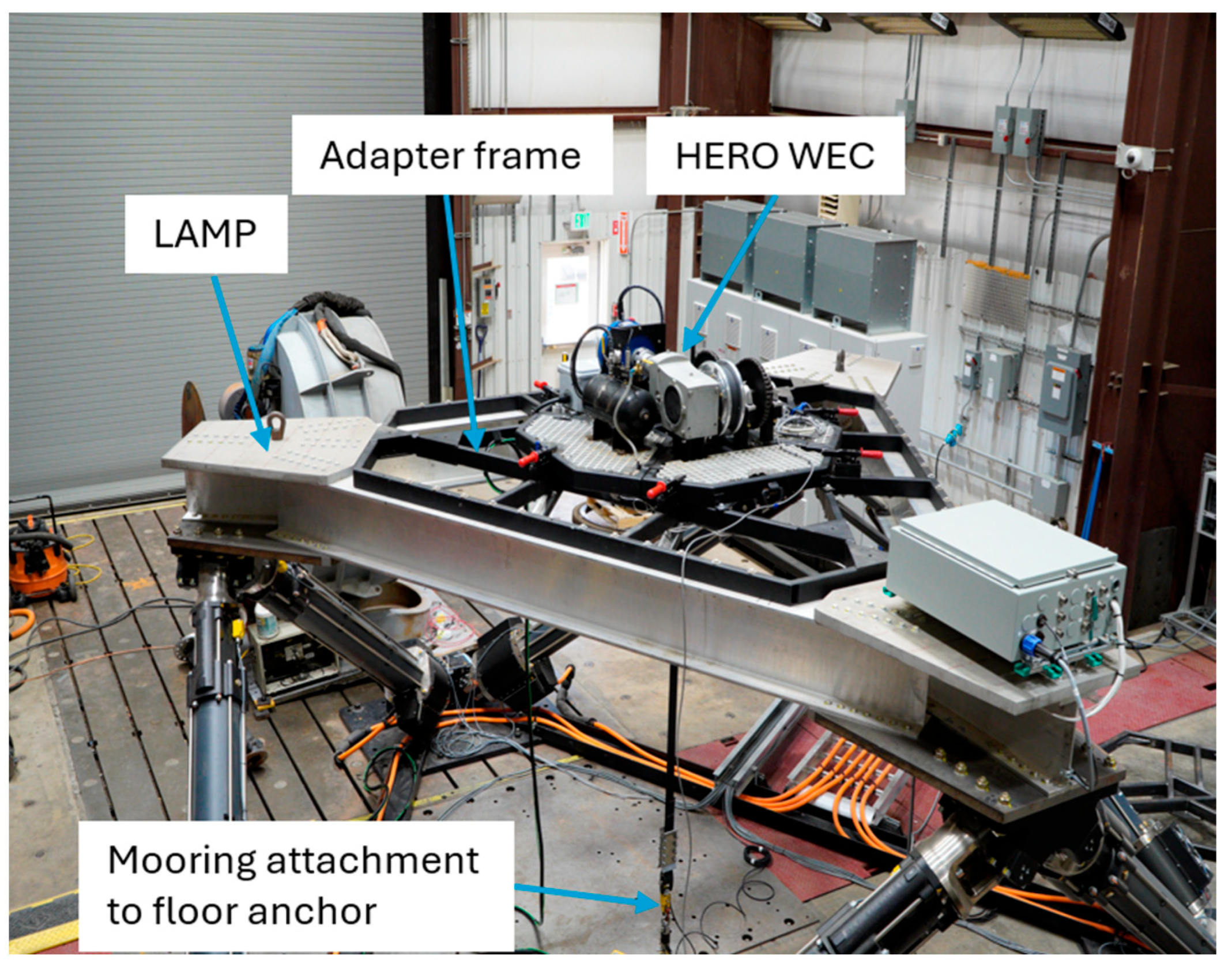
Belt testing was conducted using the HERO WEC and LAMP, which is a six-degree-of-freedom platform that has been adapted for testing different WEC designs. During testing, a WEC is secured to an adapter frame on top of the LAMP, and its mooring line is attached to a floor-mounted anchor point (
Figure 4). LAMP is capable of moving the WEC through motion profiles consisting of up to 1.8 m of heave displacement, 2.5 m of surge displacement, and 2.3 m of sway displacement [
8]. LAMP can operate with payloads of up to 10,000 kg. The HERO WEC is rigidly attached to LAMP’s payload frame for testing. LAMP operates along predefined motion profiles while a controllable AC load bank (Regatron, Rorschach, Switzerland) connected to the HERO WEC’s generator is used to simulate an electrical load, producing a mechanical load on the drivetrain and a tension load on the mooring line as LAMP moves the WEC through a variety of prescribed motion profiles. Tests were conducted in a dry environment under ambient laboratory conditions.
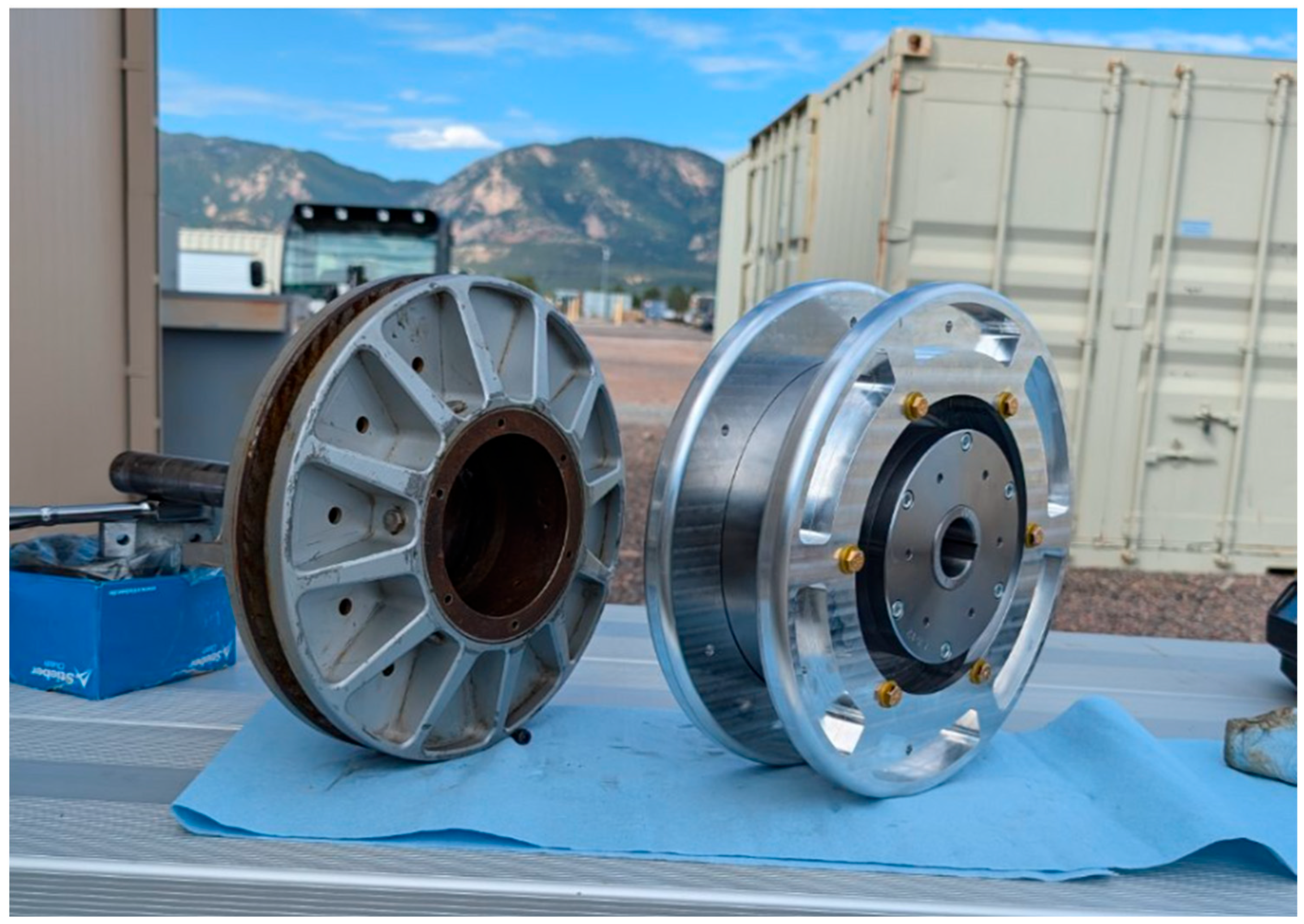
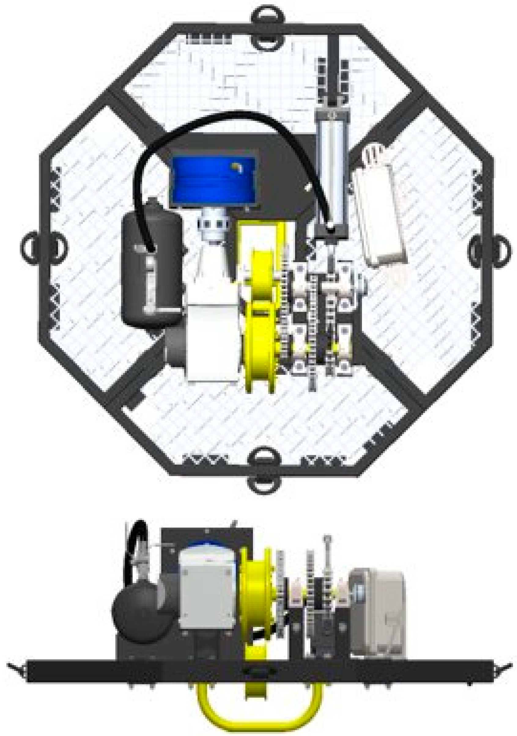
The HERO WEC was modified for this test program to allow the use of a polyurethane flat belt with the existing drivetrain. Modifications to the HERO WEC include a newly designed spiral initiating winch (
Figure 5), a new sheave pulley, and a redesigned sheave pulley guard to provide additional clearance for the belt, allowing off-axis loading to be tested (
Figure 6).
The spiral initiating winch drum (
Figure 7) follows an Archimedes spiral profile with a radius increase per revolution equivalent to the thickness of the belt used in testing. This component is designed to ensure consistent coiling of the belt with no sudden diameter changes, which may cause abrasion of the belt, shock loading, or sudden accelerations to the drivetrain. Because the coiling profile of the belt follows the spiral profile formed by the surface of the winch drum, the position of the belt and effective winch radius can be directly calculated using the equations that define the surface of the winch drum.
The angular position of the winch was measured using an encoder located in the WEC’s spring return, enabling the position of the belt to be tracked throughout testing. The polar form of the Archimedes spiral equation (Equation (1)) was used to calculate the effective winch radius at each time step. The polar arc length integral of an Archimedes spiral (Equation (2)) was used to derive a simplified arc length approximation (Equation (3)), which was used to calculate the coiled length of the belt at each time step.
In these equations, the constant a is the initial radius of the coiling surface of the winch drum, and the constant b is the radius change per radian in the belt coil. The belt drive winch developed for this test program has an -value of 105 mm and a -value of 0.52 mm/rad.
The new winch assembly was designed to meet all requirements and design guidelines set by the belt manufacturer. The belt is attached to this assembly using a clamp component, which is bolted to the winch drum. The clamp is designed to provide sufficient surface area to hold the belt when tensioned. Both the inside surface of the clamp component and the surface of the winch core that the belt is clamped against feature a machine-knurled profile as recommended by the belt manufacturer to increase friction and therefore, holding capacity. The clamp component is held in place by four bolts, which are tightened to a torque that results in a clamping pressure within the range stated in the manufacturer’s design guidelines.
The belt used in this test is the 50 mm wide version of Continental’s XHP II series of belts. The XHP II series of belt was selected since it is a commercially available series of closed and flat profile belt which fully encases the tension members that was easily integrated into the HERO WEC. The 50 mm variation in this belt was selected since its size and load ratings closely match the design requirements of the HERO WEC while allowing the use of more compact pulleys. This belt is constructed from 16 steel wire rope tension members which are encased in a 3.3 mm thick and 50 mm wide polyurethane sheath. Each wire rope tension member is constructed from seven strands of seven wires [
17]. Neighboring tension members within the belt feature opposite lay directions to ensure neutral twisting properties [
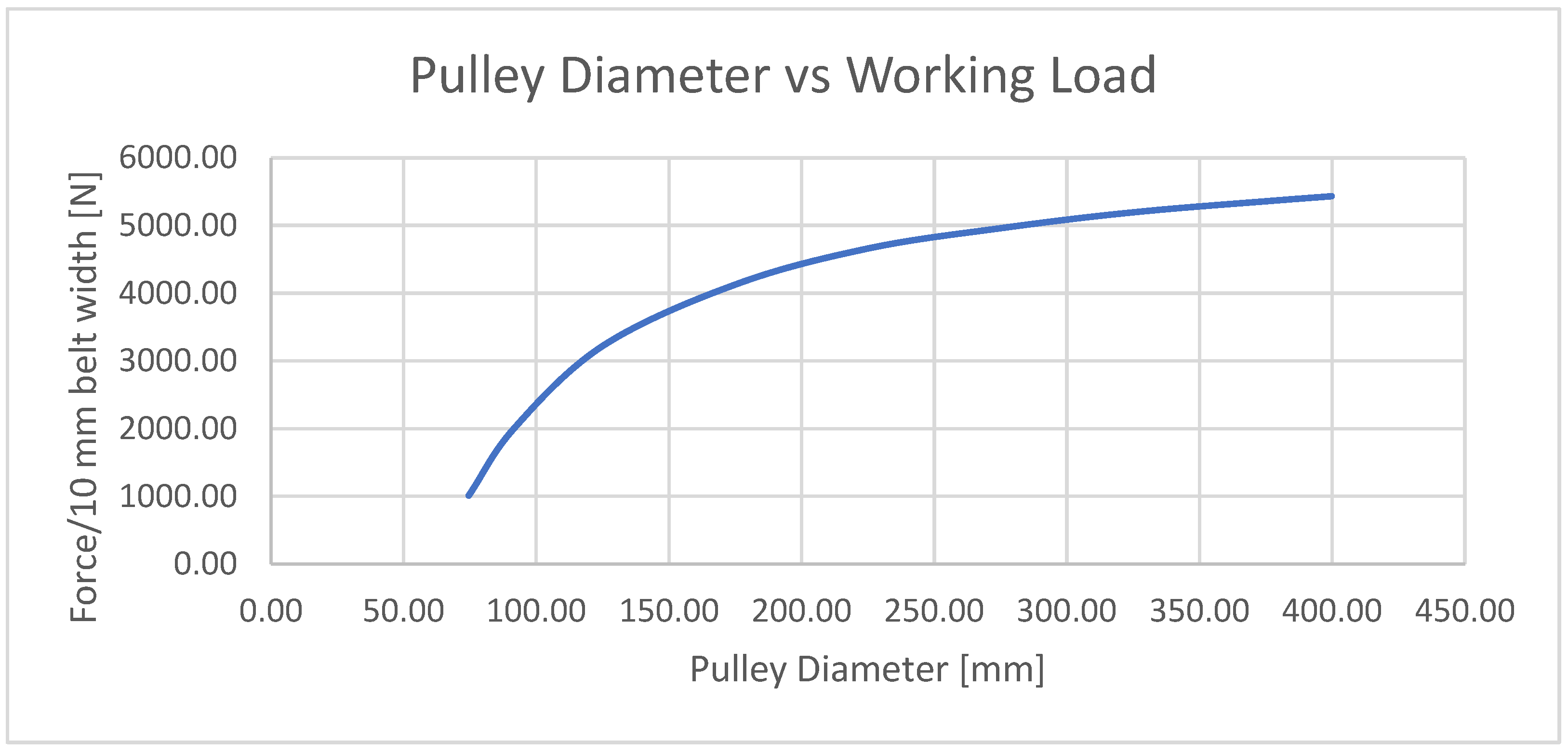
17]. This series of belts is designed to achieve a service life of several million [
17] bending cycles over small-diameter pulleys when loads are maintained below the maximum tension load per 10 mm of belt width, as shown in
Figure 8.
This test program aims to evaluate if polyurethane flat belts are suitable for marine energy applications by determining if they can withstand load cases that are frequently encountered in this application. During testing, a tension link load cell is used to measure the tension that the belt is subjected to. The encoder, mentioned previously, is used to approximate winch position by measuring the position of the second-stage shaft of the spring return, which can be used to calculate the winch position and velocity profile (
Figure 9). Additionally, generator output voltage and current measurements are collected along with air spring pressure measurements, but these data streams are only used for monitoring the health of the device during testing. Information on all sensors used in testing and their sample rates can be found in
Appendix A,
Table A1 and
Table A2. Physical measurements of the belt thickness and width were taken using a set of Mitutoyo digital calipers at the beginning and end of testing to evaluate abrasion to the surfaces of the belt.
This test program consists of two portions, a static load evaluation and a dynamic load evaluation. The static load evaluation aims to evaluate the holding capacity of the belt’s attachment to the winch drum. Failure during this test was defined as any belt slippage from the clamp, tearing or breakage of the belt, or mechanical failure of the clamp mechanism. This test was conducted with the spring return disconnected, allowing the winch to rotate so that the belt was loaded radially outward from the winch when the weight was lifted. The dead wraps—coils of line that remain on the drum at all times during operation to act as a frictional attachment point between the drum and line—were omitted for this test to evaluate the holding capacity of the clamp mechanism alone in the most extreme load case, which the winch could be subjected to during operation. In this test, the anchor end of the belt was attached to a calibrated weight, and the HERO WEC was lifted by an overhead crane until the calibrated weight was lifted off the floor. This position was held for one minute, and then the weight was slowly set down. This procedure was repeated four times with each weight. Following each run in this portion of testing, the system was thoroughly inspected for any signs of belt slip, and the weight was increased for the next run. This test was repeated using weights of approximately 2200 N, 4400 N, and 8900 N, corresponding to 500 lbs, 1000 lbs, and 2000 lbs, respectively.
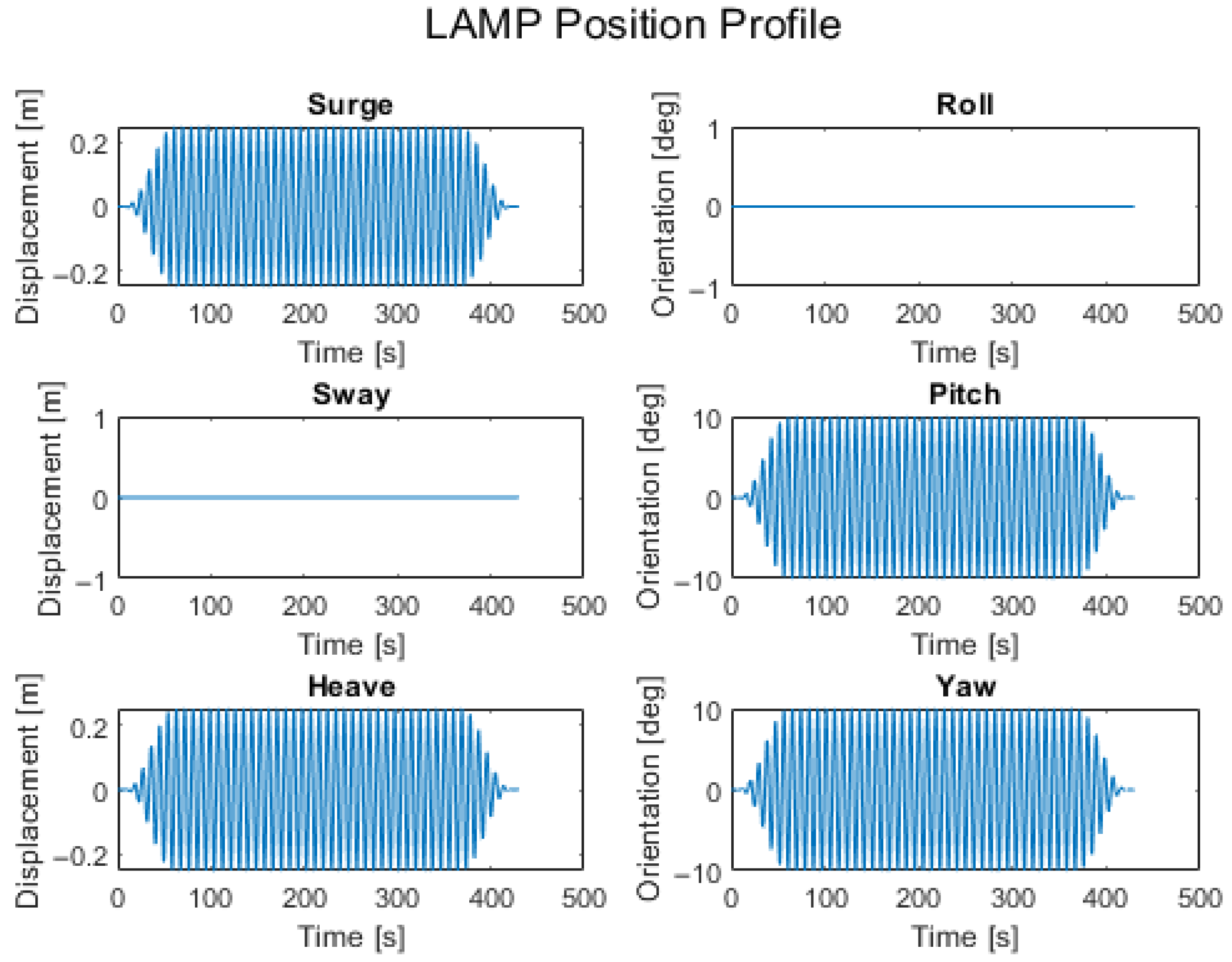
The dynamic load evaluation portion of this test program aims to understand the belt’s resistance to the abrasion, off-axis loading, and twisting, which occur during normal operation of a single-mooring point-absorber-type WEC. Failure during this test is defined as tearing or breakage of the belt, belt slippage from the clamp, or abrasive wear to the belt which exposes tension members or otherwise prevents the belt from functioning as intended. In these test runs, LAMP was operated with motion profiles of up to four degrees of freedom (heave, surge, pitch, and yaw). An example of the four degrees of freedom motion profile can be found in
Figure 10.
Initial cases consisted of small-amplitude, long-period waves to verify that the newly designed winch and sheave pulley functioned as intended and to allow the AC load bank to be tuned to achieve the desired anchor loads. The frequency and amplitude of the wave profiles were gradually increased to accelerate the belt-to-belt abrasion caused by coiling on the winch drum and to identify if this is a cause of significant wear. Initially, test profiles consisted of one or two degrees of freedom with the winch drum, sheave pulley, and anchor in the same plane. After confirming that the belt performed as expected in heave and surge, additional degrees of freedom were introduced. Sway offsets were applied to simulate off-axis loading, representing conditions such as WEC displacement due to wind or cross currents. Oscillatory yaw motion was also added to replicate the twisting observed during previous ocean deployments. These additional degrees of freedom were intended to unevenly load the tension members, representing real-world conditions that could lead to issues such as the “detach and snapping” behavior observed by the team from Sandia National Laboratories [
10], inter-layer slip on the winch drum, or uneven coiling.
3. Results
Throughout testing, the polyurethane flat belt was observed to withstand all load cases that it was subjected to. The static testing revealed that the clamp used to attach the belt to the winch drum was capable of withstanding multiple 8900 N load events without a dead wrap. The dynamic test cases revealed that the uneven coiling and uncoiling tensions result in unmeasurable layer-to-layer abrasion of the coiled belt while the working section of the belt was found to show no measurable abrasion from running over the sheave pulley and winch drum. Dynamic tests also revealed that the belt can withstand the twisting and off-axis loads, which a mooring line in this application would be subjected to. Throughout this entire set of tests, no obvious signs of fatigue or wear were observed.
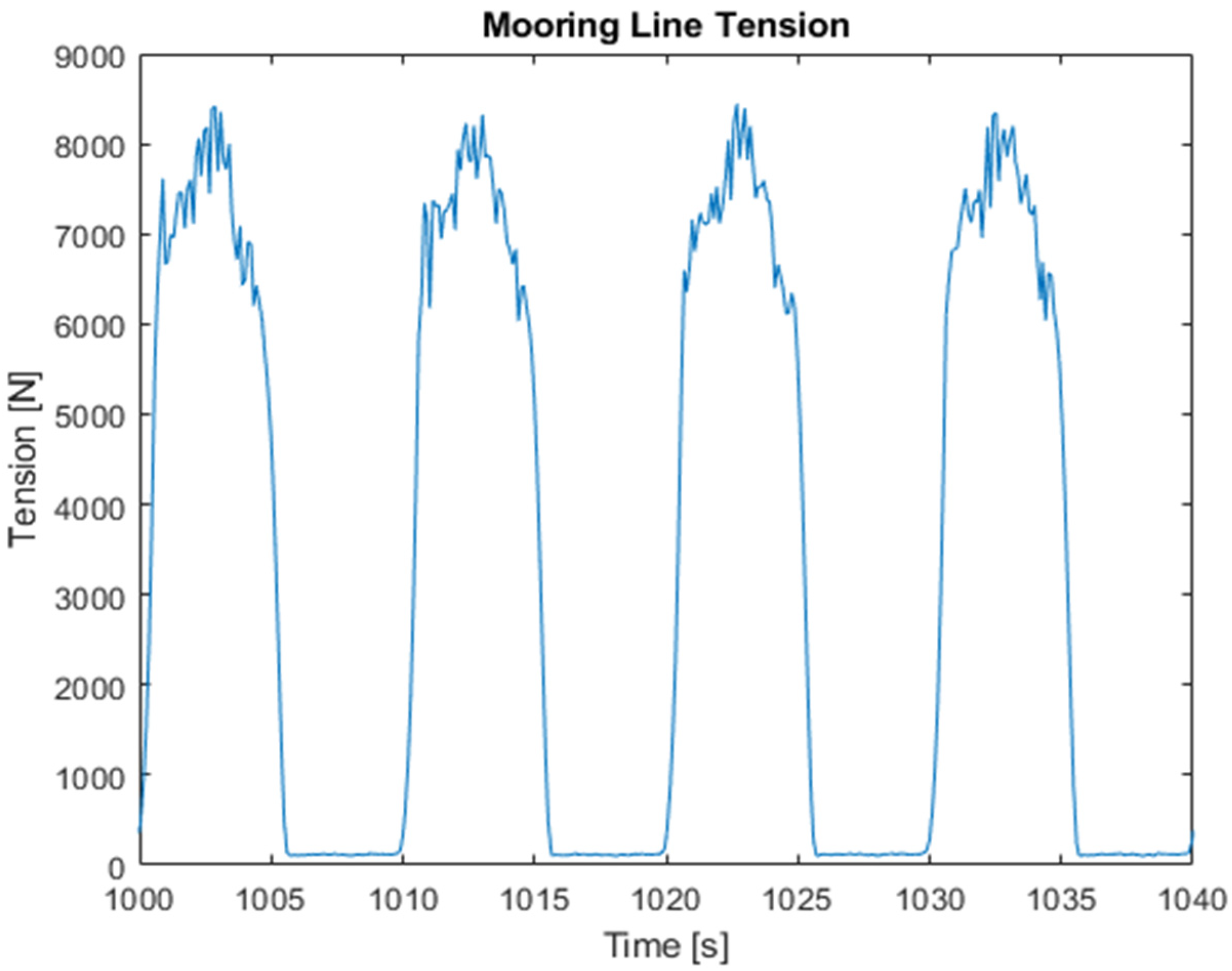
During the dynamic tests, the belt was subjected to a total of 27,547 load cycles or simulated waves, resulting in a tension profile similar to
Figure 11 where the belt is uncoiled with a tension load of up to 6000 N and then recoiled with a tension load of approximately 180 N. A count of the number of load cycles which the belt was subjected to in each wave type can be found in
Table 1. A summary of the load cycles that the belt was subjected to during this portion of testing is publicly available in
Supplementary Material (MHKDR Submission 589 [
18]).
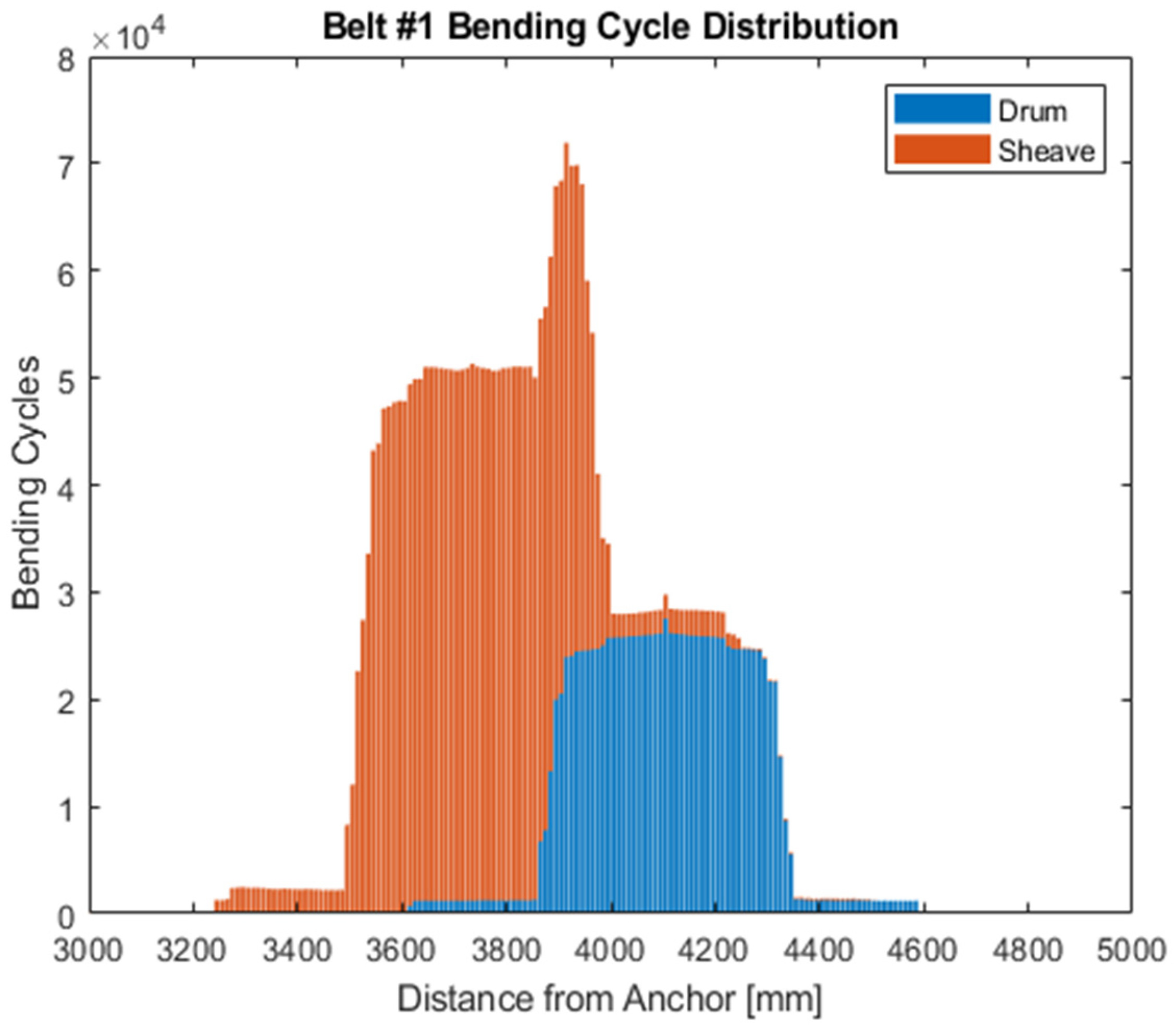
The distribution of bending cycles on the belt used for dynamic testing can be found in
Figure 12. This plot shows bending cycles regardless of tension, and it should be noted that within each load cycle, the belt is subjected to both high-tension bending cycles as the WEC moves away from its anchor and low-tension bending cycles as the WEC moves toward its anchor. Motion profiles used in testing were selected to achieve an overlap of the region of the belt subjected to bending over the sheave pulley and the region subjected to bending on the winch drum in each load cycle to accelerate the fatigue and abrasion the belt is subjected to. This region existed between 3860 mm and 4000 mm from the anchor end of the belt. The section of the belt between 3910 mm and 3920 mm from the anchor end was subjected to the most bending cycles in this study (71,914 bending cycles) (
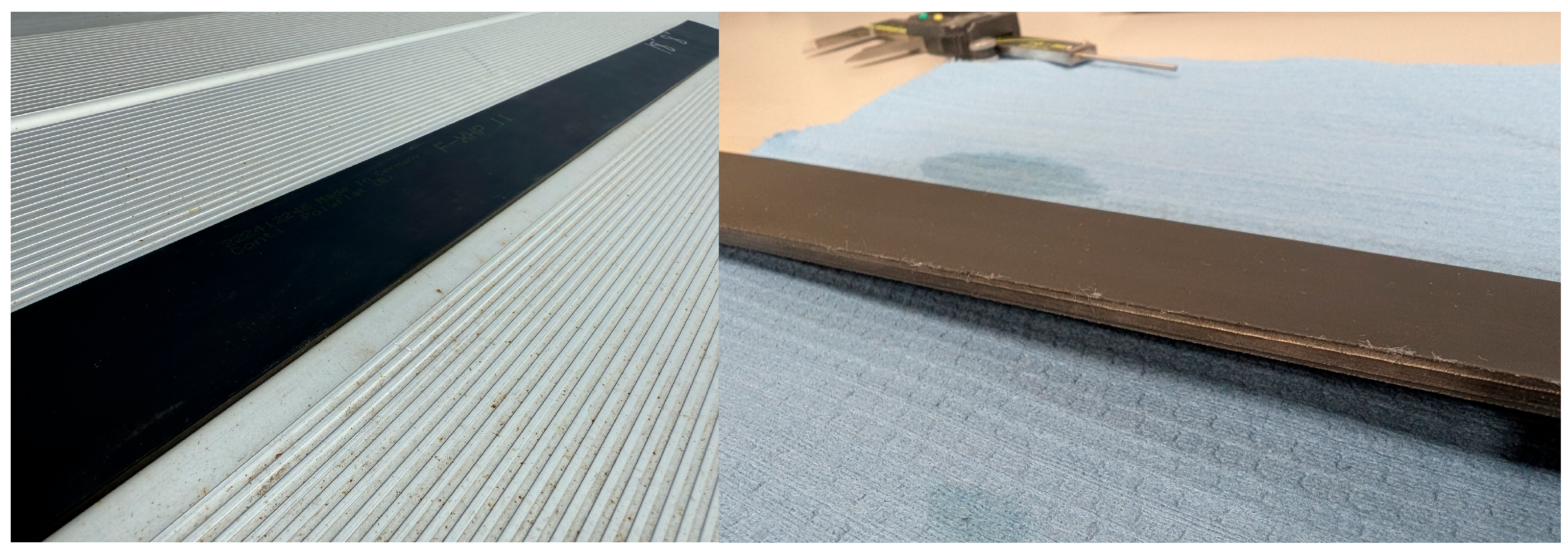
Figure 12). Minor visible signs of abrasion were observed in this overlapping region on one edge of the belt that contacted the sheave pulley face and flange in operation. Wear in this region was concentrated at the corner of the belt and did not structurally compromise the belt or expose any tension members.
Figure 13 shows the abraded edge of the belt used during testing compared to the belt in its new condition.
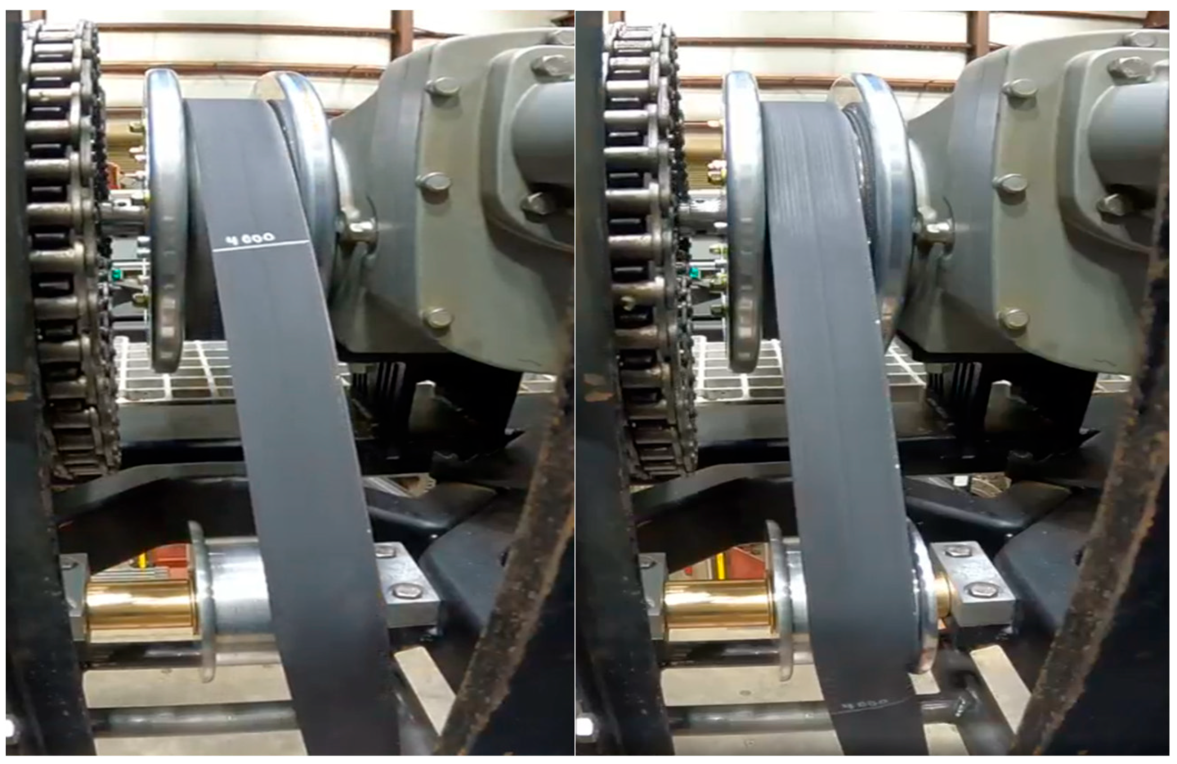
During test cases with sway offsets, the belt was observed to contact the sheave pulley flange and begin to lift off of the sheave pulley face. In cases with significant sway offsets, the belt was observed to lose contact with the face of the sheave pulley and move partly over the flange, shown in
Figure 14. In these same test cases, signs of uneven loading were observed at the belt’s lower contact location with the sheave pulley. When tensioned, the belt angled and ran directly to the anchor location; however, when recoiling under low tension, the belt was observed to be slacked on the low-tension side with a slight bend visible across this side of the belt immediately below the point where the belt runs onto the sheave pulley (
Figure 14). In these cases, the coils were observed to axially shift on the winch, with the belt contacting the PTO side flange under high load and the spring return side flange under low load. The shifting coils result in an uneven contact pressure distribution on the winch drum as coils stack without being centered on the coil below. This is expected to produce uneven stress distributions across the width of the belt.
Following the dynamic tests, measurements of the belt’s thickness and width were taken every 100 mm along the length of the belt and compared to measurements taken at the same locations before testing. All measurements were taken using Mitutoyo digital calipers. Due to the flexible nature of the belt’s polyurethane coating, some inaccuracy is expected in these measurements. Comparing these measurements, it was found that with the exception of the corner wear (
Figure 14) resulting from the belt contacting the flange of the sheave pulley, no measurable change in thickness or width was found, indicating negligible wear. The post-test inspection also revealed that the belt deformed in the regions where it was clamped, showing a slightly reduced thickness and increased width. An indentation of the machine-knurling profile used on each clamping surface was also visible on the belt’s surface in each clamping region. During this inspection, aluminum dust was identified on the contact surface of the belt that was subjected to bending over the sheave pulley. The dust was identified as a result of wear to the outside surface of the aluminum sheave pulley. The distribution of dust on the region of the belt subjected to the most bending cycles shows the profile of the high-pressure regions resulting from the distribution of tension members across the belt in the contact patch between the belt and pulley. The aluminum dust was found to be easily cleaned from the belt’s surface, and no measurable damage to the polyurethane was found at this location (
Figure 15).
4. Discussion
Testing of polyurethane flat belts as mooring lines for winch-based WECs has shown that the belts can withstand the load cases they are subjected to in this application. Combined with their design fatigue life, which far exceeds that of wire rope for a given bending diameter, the testing results make polyurethane flat belts a strong candidate for use as mooring lines in wave energy applications. The static tests have shown that the method used to attach a polyurethane flat belt to a winch can withstand the HERO WEC’s expected end stop load cases, and dynamic tests have shown that this clamp design is compact enough that it does not interfere with the primary functionality of the winch. In this test program, no measurable or visible signs of fatigue were detected on the belt after 27,547 load cycles, whereas a wire rope mooring line used in a similar previous test program with the HERO WEC showed severe signs of fatigue, including broken wires after just 13,896 load cycles. Dynamic tests have also shown that uneven coiling tension results in no noticeable abrasion to the belt’s polyurethane coating and that belt-to-belt abrasion may not be a significant concern in this application. Although signs of layer-to-layer abrasion were not observed during these tests, abrasion was observed on a corner of the belt that frequently contacted the flange of the sheave pulley during testing, indicating that flange contact may accelerate abrasion and that systems should be designed to minimize the belt’s contact with flanges during operation. When compared to wire rope mooring lines used on the HERO WEC during previous test programs and deployments, the lack of visible signs of fatigue on the belt used for dynamic testing indicates that the fatigue life of a polyurethane flat belt in this application is equal to or greater than wire rope.
To date, Abdellatef et al. [
10] represent the only comprehensive study investigating polyurethane flat belts in marine energy applications, making their work the primary basis for comparison. This study differs significantly from previous work but provides complementary insights. Abdellatef et al. [
10] conducted full-scale testing of a polyurethane flat belt on a friction drive drum and found that off-axis loads and fleet angles led to polyurethane abrasion and eventual exposure of the belt’s tension member, which was identified as the likely failure mode. Their study emphasized that even small fleet angles made it difficult for the belt to maintain contact with the drum and concluded that strict fleet angle limits would be necessary in WEC systems. In contrast, the present study employed a multi-layer winch drum rather than a friction drive system, resulting in lower shear stresses within the belt and different contact mechanics. While the test duration in this study was shorter (27,547 load cycles versus 847,612 in [
10]), abrasion was found to be minimal. Both studies identify large fleet angles as a critical factor for belt stability, reinforcing the need for careful alignment in belt-driven WEC designs.
Although polyurethane flat belts have shown potential as a wire rope replacement in this application based on their structural properties and performance in winch-based systems, these tests also revealed that the belt’s limitations in this application will require additional design changes to properly integrate polyurethane flat belts into this WEC application. Due to the interactions of the belt and sheave pulley flange observed in offset wave cases, the use of fairlead systems is recommended to constrain the belt at the location where it enters the WEC. This fairlead system should be designed to minimize the possibility of the belt bending against the flanges of the rollers. Since polyurethane flat belts can handle a limited amount of twisting per unit length, mooring designs which limit twisting of the WEC relative to its anchor or incorporate rotating anchor attachments which can relieve twist are recommended. Additional environmental risks which may impact performance, such as water intrusion through the polyurethane and corrosion of the tension members are still unknown and require future evaluation.
Additionally, the belt’s ability to withstand long-term exposure to a marine environment is not yet well understood. In this environment, the belt will be exposed to seawater, which presents corrosion concerns for the tension members, as well as ultraviolet light, which may degrade the polyurethane coating material. The belt’s resistance to biofouling, where marine growth attaches to the surfaces of the belt and could lead to accelerated abrasion between coils of the belt on the winch, is also not known. These concerns highlight the need for future biofouling and corrosion resistance testing in a marine environment.
Based on the results of the experiments conducted, a polyurethane flat belt is being considered for use on the HERO WEC V2 prototype, which is expected to be deployed in the summer of 2026. This prototype would incorporate the design changes that were identified in this test program as recommended for the use of a polyurethane flat belt in this application. Changes would include a specially designed fairlead to align the belt with the winch at its first contact point with the WEC and a narrower winch drum to maintain more consistent coiling. The HERO WEC V2 is expected to provide an opportunity for these design changes to be evaluated in lab testing and in ocean deployments, which will enable the collection of additional fatigue and wear data with a higher number of load cycles than this test program.
