1. Introduction
With the exploration of marine resources, the importance of underwater robots in the field of resource exploration, environmental monitoring, marine engineering, and military fields is becoming increasingly prominent [
1,
2,
3]. However, the complexity and unpredictability of underwater environments place higher demands on the development, control, and commercialization of underwater robots. In particular, the problem of energy power, which is directly related to the working hours, operating costs, and adaptability to extreme environments of the underwater robot.
Compared to traditional underwater robots, amphibious robots can move in both land and water environments. Therefore, amphibious robots can move more flexibly in irregular terrain. To enhance the collaboration ability and communication stability of the amphibious spherical robot, Zheng et al. [
4] designed an electronic communication module based on the mechanical structure and dynamic model of a spherical amphibious robot. The communication performance of the proposed communication module is experimentally verified under still water, obstacles, and natural water. Aiming at the amphibious robot facing variable working conditions and harsh conditions in unknown environments, and the problems of poor maneuverability, high energy consumption, and complex control of traditional fixed propulsion, Yin et al. [
5] proposed a decentralized hierarchical motion control method based on deep reinforcement learning. The experimental results show that this method improves the exploration efficiency of the amphibious robot’s motion in unknown environments. Aiming at the problems of complex structure and difficult miniaturization caused by multi-system coupling for the traditional amphibious robots, Wang et al. [
6] proposed a miniature amphibious robot based on the rigid–flexible hybrid vibration module. This robot achieves amphibious motion through a single vibration drive mechanism without the transmission mechanism and joints, which greatly simplifies the structure and reduces the size. Milana et al. [
7] developed a bioinspired multimodal amphibious robot composed of five pneumatically driven elastic modules. These modules are independently adjustable and are driven by air pressure. By altering pneumatic control sequences, the robot is able to switch between crawling on land and swimming in water. Hwang et al. [
8] reported a soft amphibious robot driven by a shape-memory-based alloy that mimics the crawling motion of seals on land and underwater. The robot exhibits both crawling land motion and oscillating underwater propulsion gaits.
The above research focuses on enhancing the motion capability of existing amphibious robots in water and land environments by changing the motion control methods or communication mode. For the amphibious robot, improving endurance while ensuring safety and reliability is of great significance to enhance adaptability in a variable environment and extend the working range. Existing power supply systems for amphibious robots can be divided into three main types: battery-based, external fluid-based, and external energy power supply. For the battery-based power supply, fuel batteries offer high electrical energy conversion efficiency, generate more electrical energy from the same amount of fuel, and operate with low noise. However, the response speed of fuel batteries is slow and cannot track the rapid changes in loads in real time. This problem can be solved if a lithium battery is added to the system. However, when there is a sudden increase in power, such as when starting, it will cause a shock to the lithium battery, affecting the lithium battery’s life [
9,
10]. For the external fluid-based power supply, the large size of the drive system and the complex field environment limit the feasibility of the pneumatic power supply in practical engineering. For the external energy power supply, the amphibious robot based on shape–memory alloy drives has high drive voltages, low energy utilization, and requires an external power supply [
11].
Wave energy is a high-quality offshore renewable energy source with large reserves. It is green and clean, and sustainable utilization [
12]. The basic working principle of the wave energy generator is to utilize the continuous motion of waves to drive the power generator and convert the captured wave energy into mechanical energy of the moving parts in the device, which is then converted into electrical energy. At present, wave energy power generation systems can be mainly categorized into the following groups based on the type of power output system: mechanical drive system [
13,
14] electromagnetic drive system [
15,
16], hydraulic drive system [
17,
18], pneumatic air turbine device [
19], hydraulic turbine drive system [
20], friction electric nano-generator [
21,
22], and wind–wave hybrid energy system [
23,
24]. Among them, the direct drive system of permanent magnet (PM) linear generators in electromagnetic drive systems has a simple structure and does not require additional mechanical devices to transmit motion, eliminating intermediate energy conversion links and significantly improving energy capture efficiency [
25,
26,
27].
Inspired by the above problems, this paper proposes a power supply system for the amphibious robot to extend the working time. The system is based on wave energy harvesting and is designed for the operation and maintenance of near-shore floating photovoltaic systems. In addition, the induced electromotive force (EMF) is one of the critical output indicators for the designed linear wave generator [
28], in which its amplitude, waveform, and phase directly affect the power quality and power output. The amplitude and stability of the induced EMF for the designed generator are improved by optimizing electromagnetic parameters. The main contributions of this work are as follows:
- (1)
A cylindrical power generator based on wave energy generation was designed to provide partial power for the amphibious robot. This helps reduce amphibious robots’ dependence on batteries, improves energy utilization, and further enhances their adaptability in a variable environment.
- (2)
The effects of the material, magnetization pattern, end effect, size, and air gap length of the PM on the generator’s performance are analyzed in detail. This provides a reference for determining the electromagnetic parameters of the designed cylindrical generator.
- (3)
A cylindrical generator is fabricated, and different wave motions are simulated using an oscillating motor. In addition, experiments are conducted to test the power generation performance of the designed wave energy-driven cylindrical generator and to analyze the energy storage of capacitors under different series-parallel connection conditions.
The rest of this paper is organized as follows:
Section 2 presents an overview of the proposed power supply system for the amphibious robot.
Section 3 compares and analyzes the structures of two types of generators based on motor design principles, as well as optimizes the electromagnetic parameters of the cylindrical generator.
Section 4 builds the experimental platform for the cylindrical generator and experimentally verifies its power generation performance.
Section 5 summarizes the work of this paper.
2. Overview of the Amphibious Robot
Figure 1 shows the overview of the amphibious robot. This robot can be divided into the upper half and the lower half. The upper half consists of an acrylic dome shell, main control board (ESP32), servo driver board, motor driver board, laser radar, GPS, and power supply system, while the lower half consists of a power switch, motors, and mechanical legs.
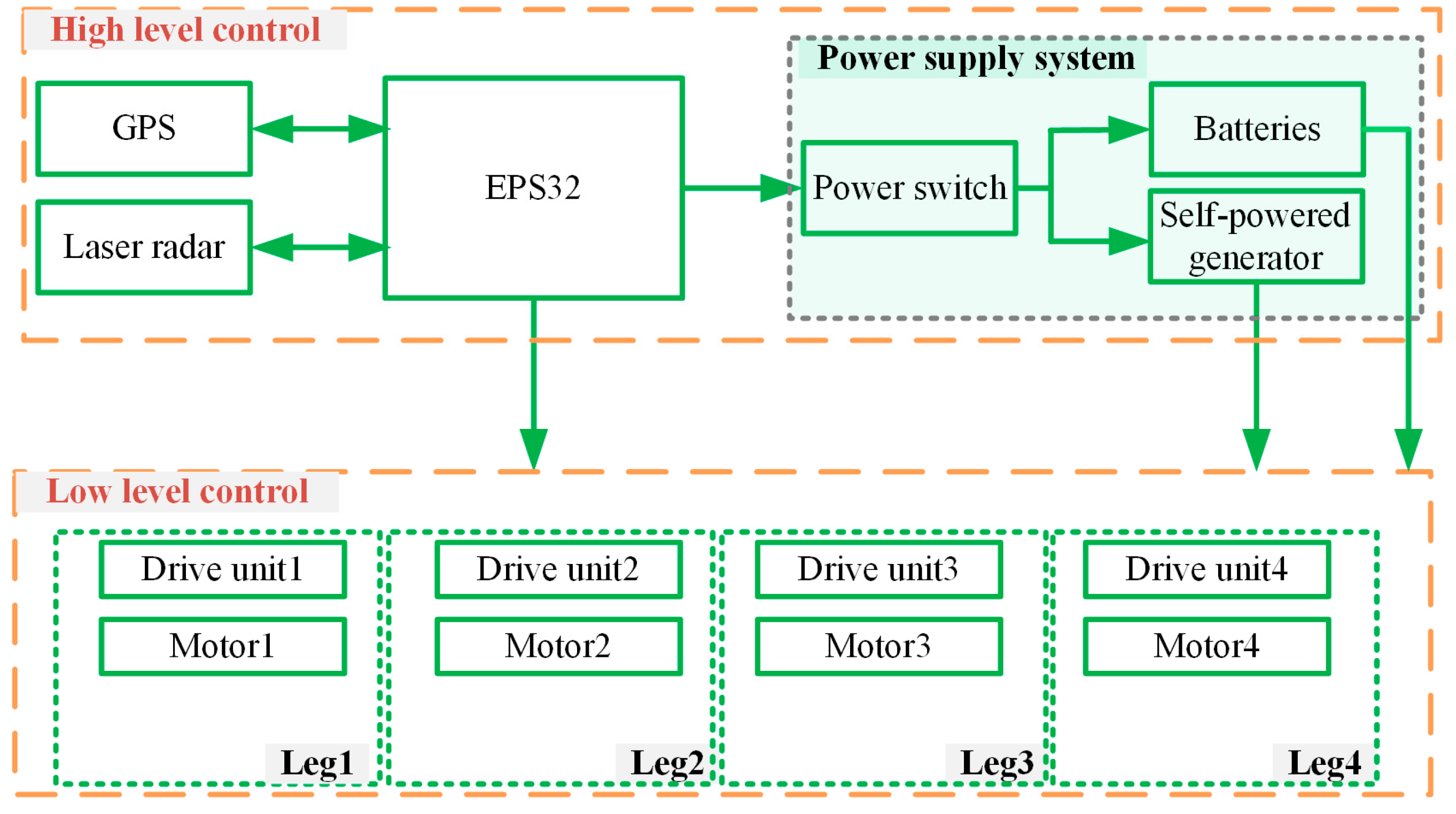
The control system of the amphibious robot can be divided into a high-level control layer and a low-level control layer, as shown in
Figure 2. The high-level control layer is used to realize the data acquisition of laser radar and GPS, the conversion of the power supply system, as well as the solution of the control algorithm for the amphibious robot. The low-level control layer is used to coordinate the movement of the mechanical legs of the amphibious robot.
There are two main parts of the power supply system. One part of the power supply system adopts the Ge 3S lithium battery, weighing about 176 g, with a capacity of 2200 mAh, an output voltage of 11.1 V, and a discharge multiplier of 20 C. The other part is a self-powered generator. It provides power to the amphibious robot by capturing wave energy during idle, converting it into mechanical energy, and then into electrical energy. Then the rectifier circuit converts the unstable alternating current (AC) into stable direct current (DC). Finally, the generated electrical energy is stored in the energy storage circuit. This helps to improve the endurance of the amphibious robot.
3. Design and Parameter Optimization of the Power Generator
In this section, the flat and cylindrical PM generators are designed for the amphibious robot. Then, the performances are simulated by ANSYS Maxwell (2021 R1, ANSYS, Inc., Canonsburg, PA, USA). Based on the simulation results, the cylindrical generator structure is selected. Subsequently, the electromagnetic parameters of the designed cylindrical generator are further optimized based on the design method of the PM linear generator.
3.1. Structural Design of the Generator
This study used laminated silicon steel with approximately 3% silicon content for both stator and rotor cores. The material offers high saturation flux density, low core losses at low frequencies, good mechanical strength, and low cost [
29,
30]. These properties make it well-suited for low-frequency wave energy harvesting and are widely used in industrial electrical equipment.
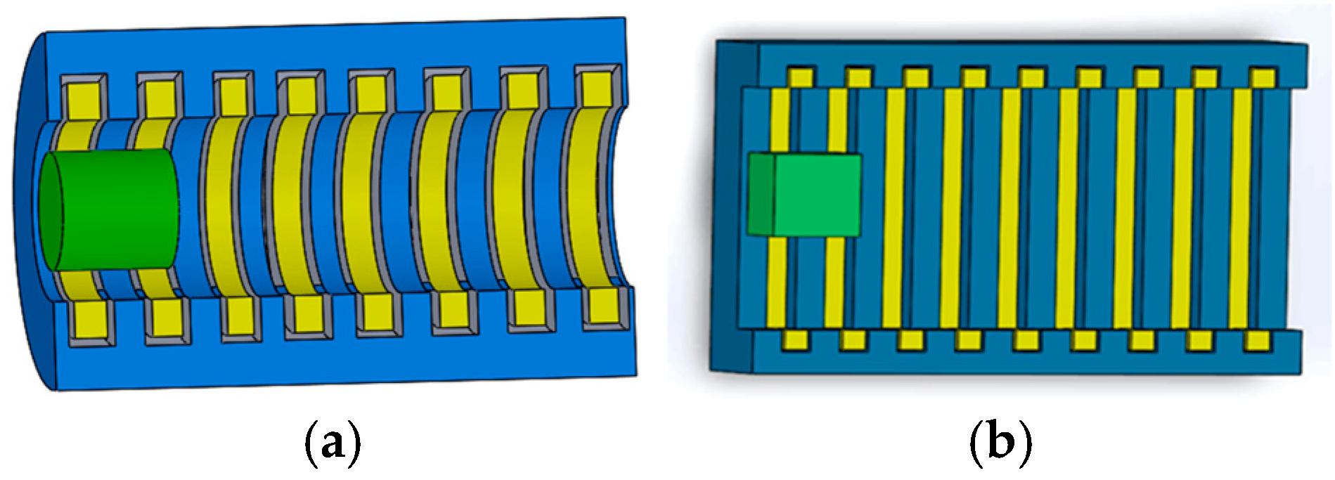
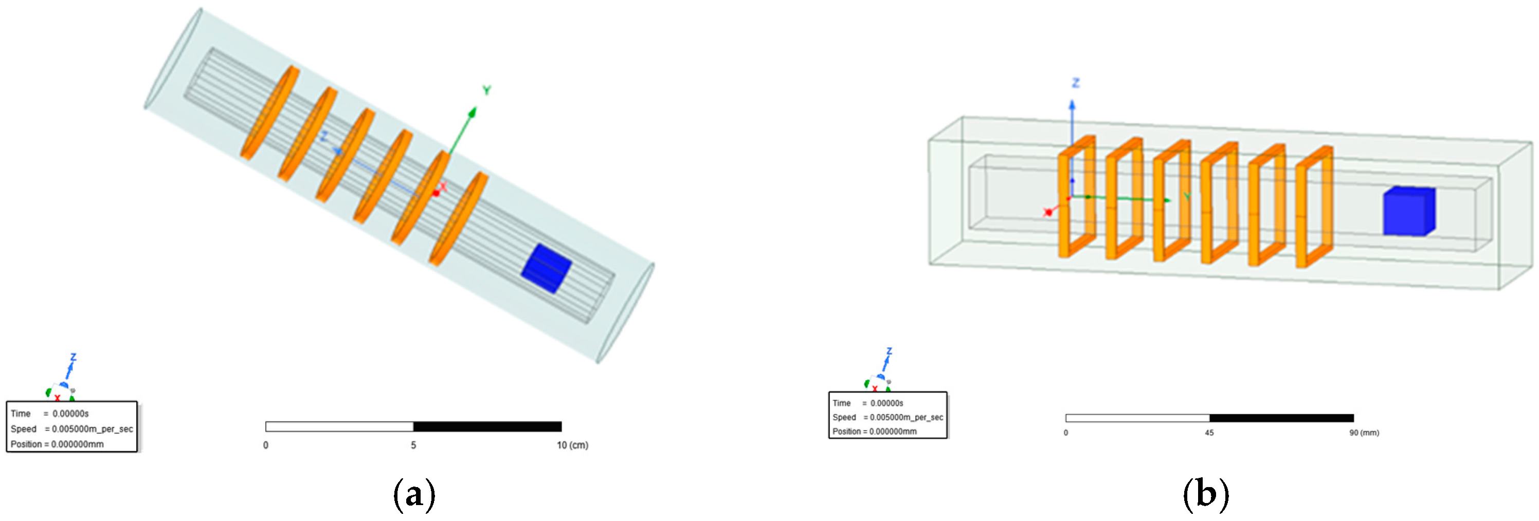
The structures of the two types of generators designed in this paper are shown in
Figure 3. The first type is a cylindrical generator, where both the coil and the PM are cylindrical. The second type is a flat generator, where both the coil and the PM are square.
3.2. Performance Comparison of Different Generators
Figure 4 shows the Two types of generators in ANSYS Maxwell.
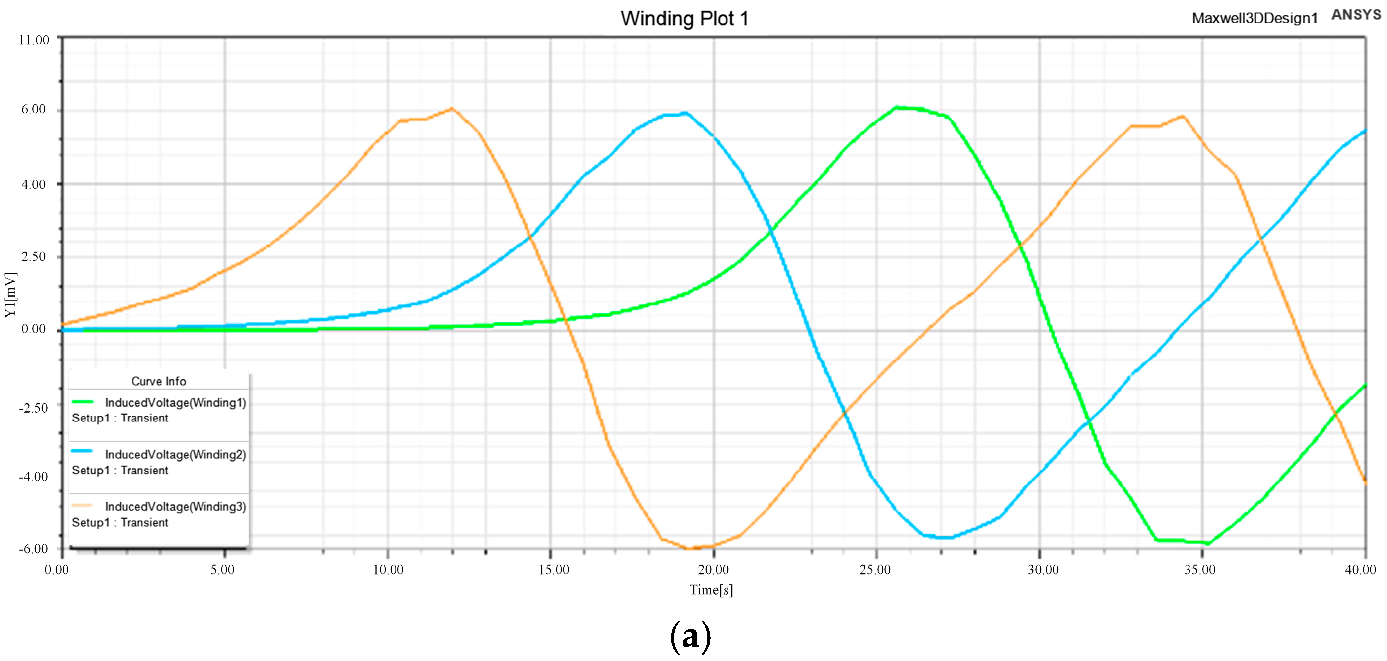
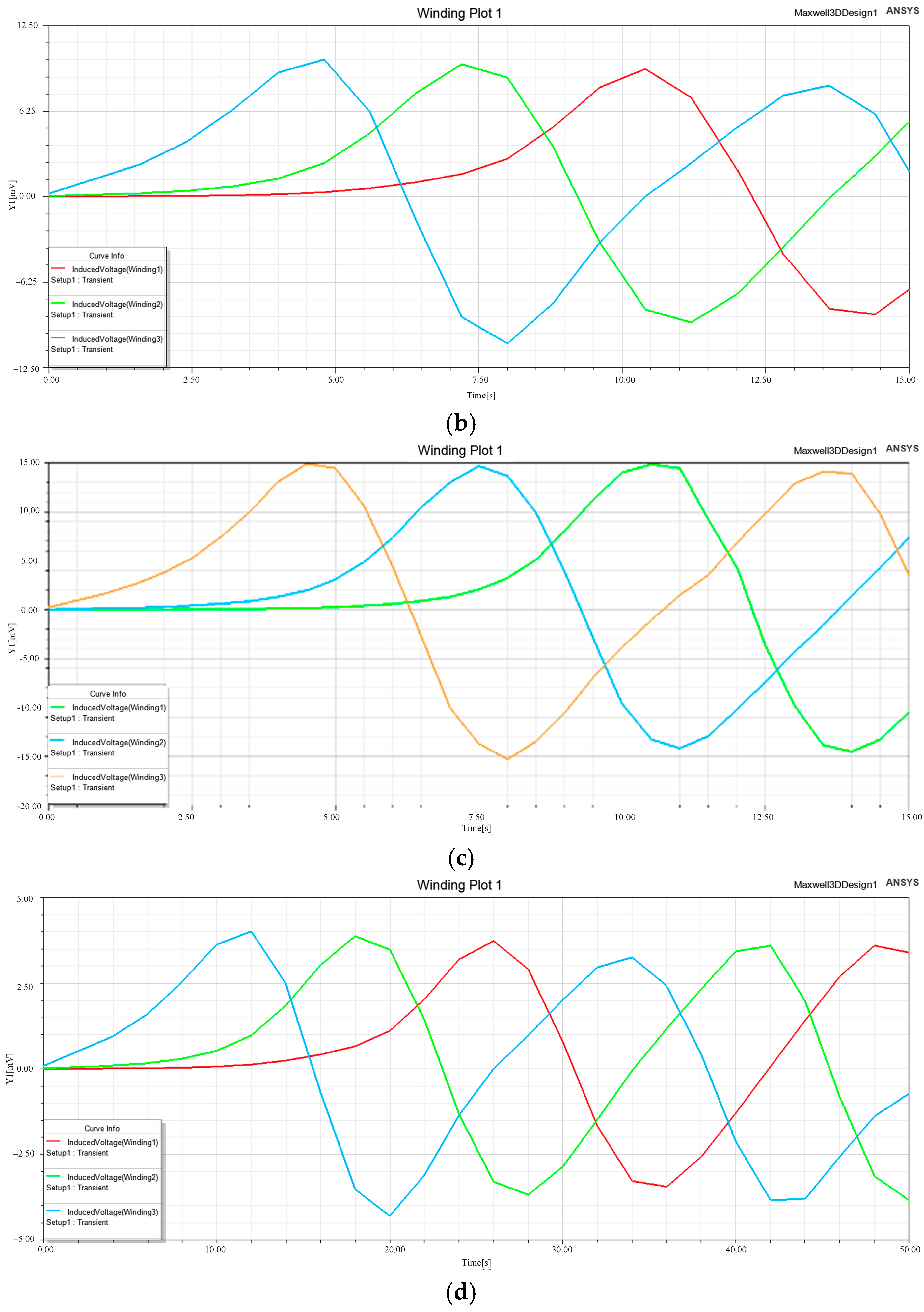
Figure 5 gives the waveforms of the induced EMF for two generators at different motor velocities, with other dimensions of the generator kept constant. It can be seen that when the motor velocity is
, the induced EMF amplitudes of phases A, B, and C for the cylindrical generator are all 6 mV, while those for the flat generator are 4 mV, 3.8 mV, and 3.73 mV, respectively. When the motor velocity is
, the induced EMF amplitudes of phases A, B, and C for the cylindrical generator are all 6 mV, while those for the flat generator are 4 mV, 3.8 mV, and 3.73 mV, respectively.
- (1)
The induced EMF is generated by the variation in magnetic flux cut by the conductor. Its waveform quality is determined by the uniformity of the magnetic flux density distribution and the symmetry of the winding structure. An approximately ideal sinusoidal waveform of induced EMF generated by the cylindrical generator. In addition, the waveform is smooth, with low distortion, indicating a continuous and stable electromagnetic induction process. In contrast, waveform distortion is observed in the induced EMF generated by the flat generator, mainly due to the uneven magnetic flux distribution and large fluctuation of magnetic flux density. This suggests that the magnetic field distribution for the cylindrical generator is more uniform and the magnetic circuit design is more reasonable. As a result, the magnetic energy conversion process of the cylindrical generator is more efficient and continuous.
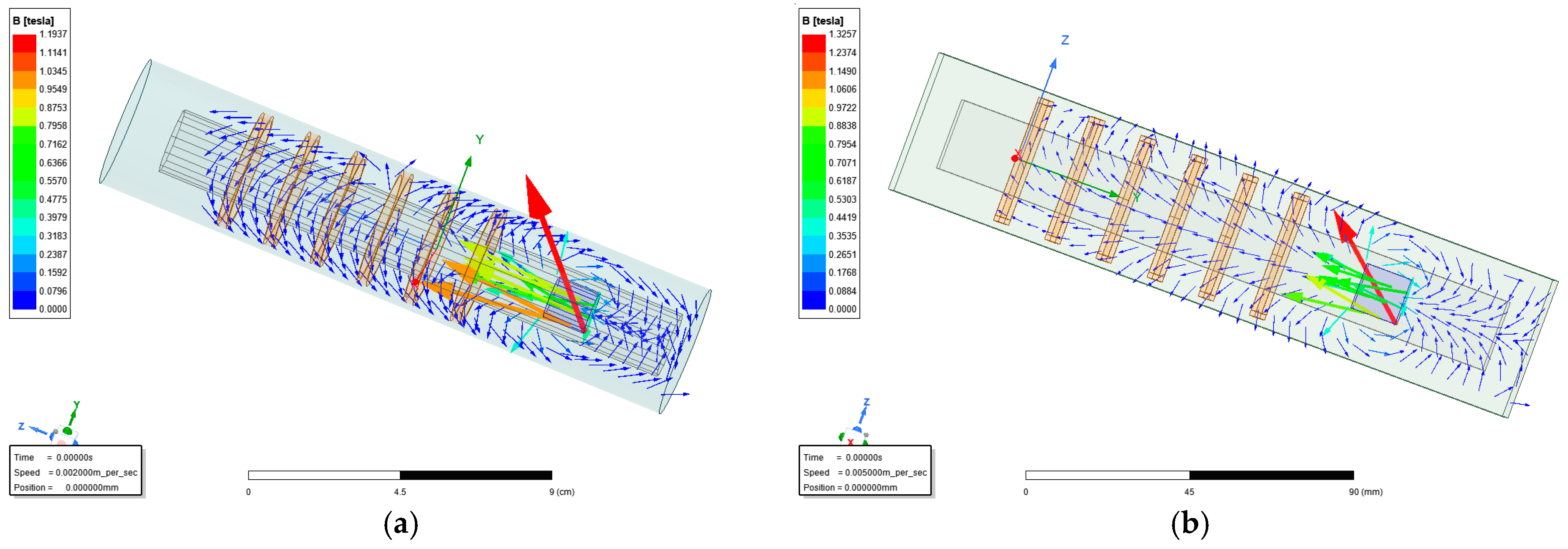
- (2)
The density and closed path of the magnetic field lines reflect the rationality of the magnetic circuit design. For the vector diagram of the cylindrical generator, a denser distribution of magnetic field lines can be observed. In contrast, the distribution of magnetic field lines for the flat generator is more scattered, and some of the magnetic field lines cannot be closed through the windings. This is due to the discontinuity or concentration of magnetic field lines at the corners of the flat generator, where magnetic flux leakage is more likely to occur. As a result, the number of effective magnetic field lines is reduced, and the distribution density decreases. This indicates that the flat generator is less efficient than the cylindrical generator in generating electricity.
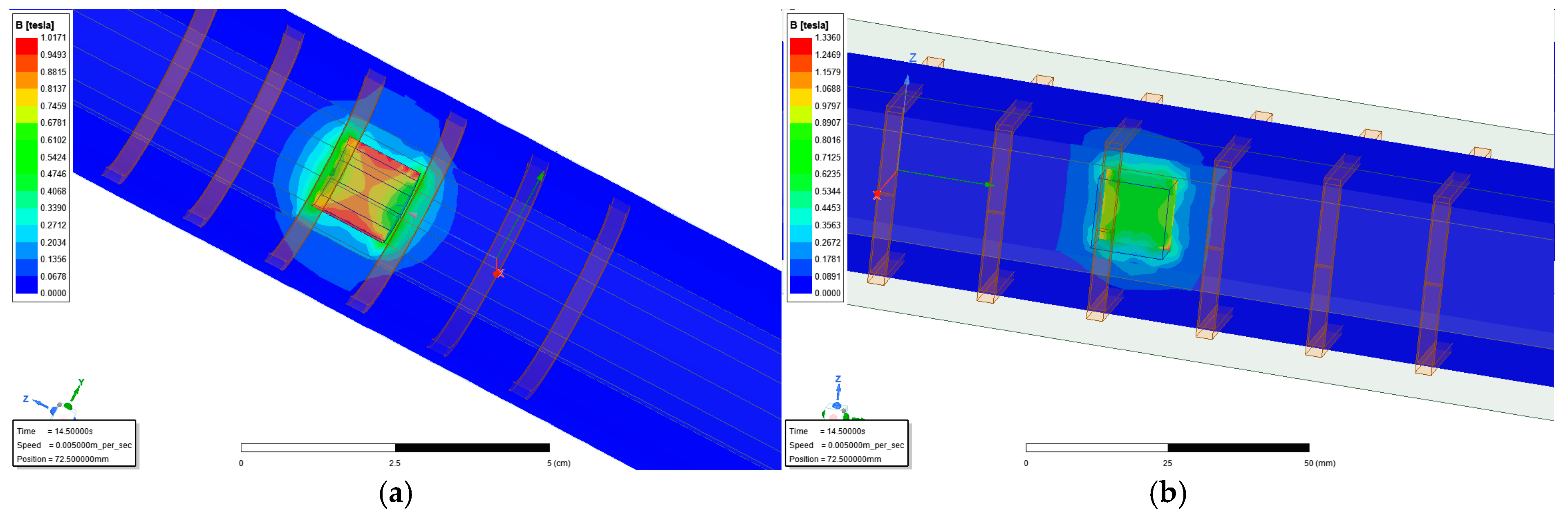
- (3)
The magnetic density cloud reflects the magnetic field strength in the working area. A more concentrated magnetic density cloud distribution is observed in the cylindrical generator, with high-density regions closely surrounding the interaction area between the stator and the PM, exhibiting clear axial symmetry. In contrast, the flat generator shows a more diffuse magnetic density cloud pattern, with smaller high-density regions and significant edge attenuation. This indicates that the cylindrical generator exhibits a more uniform magnetic field distribution and higher magnetic energy utilization efficiency compared to the flat generator.
Figure 6.
Comparison of the distribution vector diagrams of the magnetic lines for two generators. (a) Cylindrical generator. (b) Flat generator.
Figure 6.
Comparison of the distribution vector diagrams of the magnetic lines for two generators. (a) Cylindrical generator. (b) Flat generator.
Figure 7.
Comparison of the magnetic density cloud diagrams for two generators. (a) Cylindrical generator. (b) Flat generator.
Figure 7.
Comparison of the magnetic density cloud diagrams for two generators. (a) Cylindrical generator. (b) Flat generator.
The observed differences may be attributed to the structural configuration of the generator. Cylindrical generators have an axisymmetric circular configuration with windings and poles arranged in a circumferential direction. This configuration facilitates the formation of a closed and symmetrical magnetic circuit. The magnetic flux can be closed along the shortest path in a high permeability material, resulting in strong magnetic circuit continuity and low reluctance. Therefore, a high-density and concentrated magnetic field is formed for the cylindrical generator.
In contrast, the flat generator utilizes square or rectangular windings with the magnetic poles arranged at the top and bottom, respectively. This structure has geometrical discontinuities at the edges, which may not allow for complete magnetic circuit closure. The magnetic flux tends to diverge or leak as it passes through corners or boundary regions. In this topology, most of the path of the magnetic circuit is closed by air, which significantly increases the reluctance and reduces the effective magnetic flux.
In summary, compared with the flat generator, the cylindrical generator has obvious advantages in most of the performance indexes, such as voltage waveform distortion rate, magnetic density distribution, and air gap magnetic density. Therefore, the cylindrical generator is selected as the self-generating part of the amphibious robot in this paper.
3.3. Design and Parameter Optimization of the Cylindrical Generator
3.3.1. Determining the Material for PM
According to the principle of motor design, the air gap flux density of PMG directly determines the magnitude of no-load EMF, which is the core parameter affecting the power generation performance. The geometry and material properties of the PM directly affect the air gap magnetic field strength, which in turn affects the power generation efficiency and output power through the magnetic circuit coupling relationship. Therefore, for the linear generator, the material selection of the PM is critical. The main selection criteria are as follows:
- (1)
High air-gap magnetic flux density to ensure strong induced EMF;
- (2)
Good machinability and corrosion resistance for ease of manufacturing, assembly, and long-term durability;
- (3)
Stable magnetic properties under harsh environmental conditions;
- (4)
Cost effectiveness, balancing performance and economic viability.
NdFe35 PM material has the advantages of high residual magnetic induction, high coercivity, large maximum energy product, and excellent mechanical strength. Consequently, NdFe35 PM material is chosen as the magnetic source for the generator in this paper. The basic performance indicators of the NdFe35 PM are shown in
Table 1.
3.3.2. Ways of Magnetization
As shown in
Figure 8, three types of magnetization are commonly used in the PM: radial magnetization, axial magnetization, and Halbach magnetization. PM linear motors with radial magnetization have a better dynamic response and are usually used in servo systems. However, the thrust density of the motor is not high. Axial magnetization has the advantages of a simple structure, easy magnetization, and better processability. The Halbach magnetization method makes the magnetic field generated by the PM have unilateral characteristics, and most of the magnetic lines of force pass through the primary stator core of the motor. In addition, the waveform of the no-load counter EMF is more sinusoidal.
For the cylindrical PM linear generator with circular PM located on the secondary axis, using radial magnetization or Halbach magnetization will increase the difficulty of magnetization during the production process. In terms of cost, the Halbach method of magnetization results in a higher price due to the larger amount of PM used in the motor [
31]. In addition, the use of axial magnetization for the PM has been extensively studied, and the technology is more mature. Considering the performance, fabrication process, and cost factors of motors with radial, axial, and Halbach magnetization methods, axial magnetization is chosen as the magnetization method for the cylindrical generator in this paper.
3.3.3. Influence of the End Effect
The iron core of a linear motor can be equivalent to that formed when a rotary motor is cut open and unfolded. Longitudinal end effect is a general term for a series of changes in the performance and design of linear motors brought about by deformation of the magnetic field at the end of the iron core, which affects the performance of the generator. The longitudinal end effect then leads to the generation of centering forces, which further cause thrust fluctuations for the generator [
32].
To compensate for the longitudinal end effect, several methods can be used:
- (1)
Increasing the tooth area at the end of the core to reduce the reluctance;
- (2)
Changing the number of winding turns to compensate for the imbalance of the induced voltage;
- (3)
Increase the level of teeth grooves and change the winding method so that the magnetic inductance lines are closed.
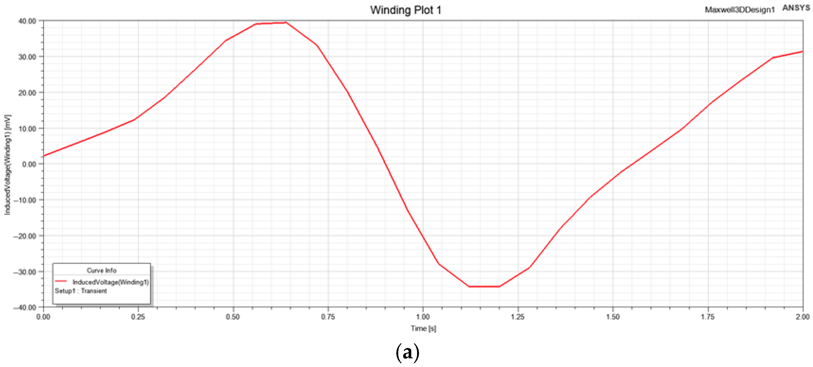
Considering that the quality of the generator design is mainly characterized by the quality of the voltage generated, this paper chooses to change the number of winding turns to compensate for the end effect. The number of winding turns in phase A of the cylindrical generator is reduced from 7000 turns to 6000, while phases B and C are kept unchanged. It can be seen from
Figure 9 that the three-phase voltages of the cylindrical generator are almost sinusoidal after reducing the number of winding turns in phase A. It can be inferred that changing the number of winding turns in phase A of the cylindrical generator effectively compensates for the end effect.
3.3.4. Effect of the Air Gap Size on the Induced EMF
The air gap is an indispensable part of the motor for electromechanical energy conversion. The size of the air gap and PM jointly determine the strength of the air-gap magnetic field. A smaller air gap improves magnet utilization, enhances demagnetization resistance, and reduces magnetic leakage, but increases harmonic components and manufacturing complexity. Conversely, a larger air gap increases magnetic leakage, reduces magnet efficiency, and weakens demagnetization resistance. Although the harmonic content and stray losses of the air-gap magnetic field are reduced, the magnetization length of the PM will increase accordingly [
33]. In addition, the coercivity of the selected PM affects the air gap length of the device. High-coercivity materials like NdFeB allow for larger air gaps, while low-coercivity materials like ferrite require smaller gaps.
For the magnetic circuit of the linear generator, the air gap is the primary source of magnetoresistance. When the excitation current and mover speed are fixed, increasing the air gap between the core and PMs reduces magnetic permeability, leading to a weaker magnetic flux linkage in the phase windings. As a result, mutual inductance and no-load EMF decrease. A larger air gap length increases magnetic reluctance, weakens the magnetic field, and reduces power output. While the air gap is essential for allowing relative motion between the stator and rotor, it should be kept as small as possible to maintain magnetic efficiency. However, minimizing the air gap length increases machining and assembly complexity, requiring higher precision during manufacturing.
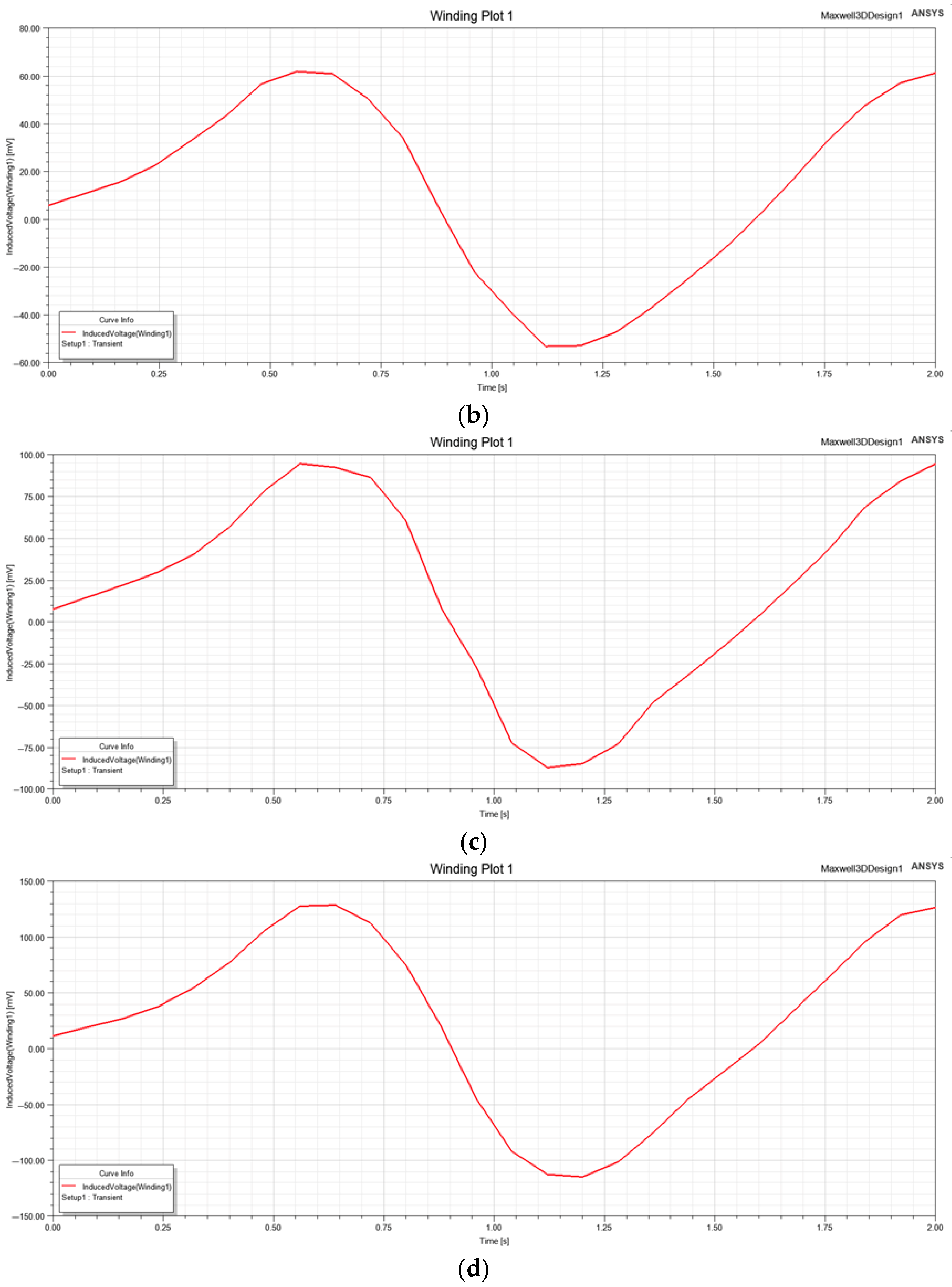
Figure 10 shows the induced EMF of the cylindrical generator at different air gap lengths. When the length of the air gap is set to 10 mm, 8 mm, 6 mm, 4 mm, and 2 mm, the corresponding waveform amplitudes of the EMF are 38 mV, 45 mV, 55 mV, 62 mV, and 75 mV, respectively. Therefore, reducing the length of the air gap from 10 mm to 2 mm significantly increases the induced EMF. Although a smaller air gap length enhances the EMF, it also introduces challenges in processing and assembly, as well as increases the risk of mechanical interference between the stator and mover. Considering the trade-off between magnetic properties, manufacturing feasibility, and practical assembly tolerances, an air gap length of 3 mm is chosen for the cylindrical generator.
3.3.5. Effect of the Size of PM on the Induced EMF
The magnetic flux generated by the PM is influenced by its height and radius. Increasing the magnet’s size enhances its magnetic potential, strengthening the internal magnetic field and improving power generation performance. However, larger magnets also increase the actuator’s mass and inertia, making control more challenging. In addition, oversized magnets can cause premature core saturation, which negatively affects performance. The size of PM also impacts flux utilization. Smaller magnets have higher no-load leakage coefficients and lower flux utilization, while larger magnets reduce leakage and improve flux efficiency. The width of the PM determines the available flux area, affecting the motor’s magnetic load capacity. A wider magnet is required for high magnetic loads to maintain the desired flux density, while a narrower magnet is sufficient for lower loads.
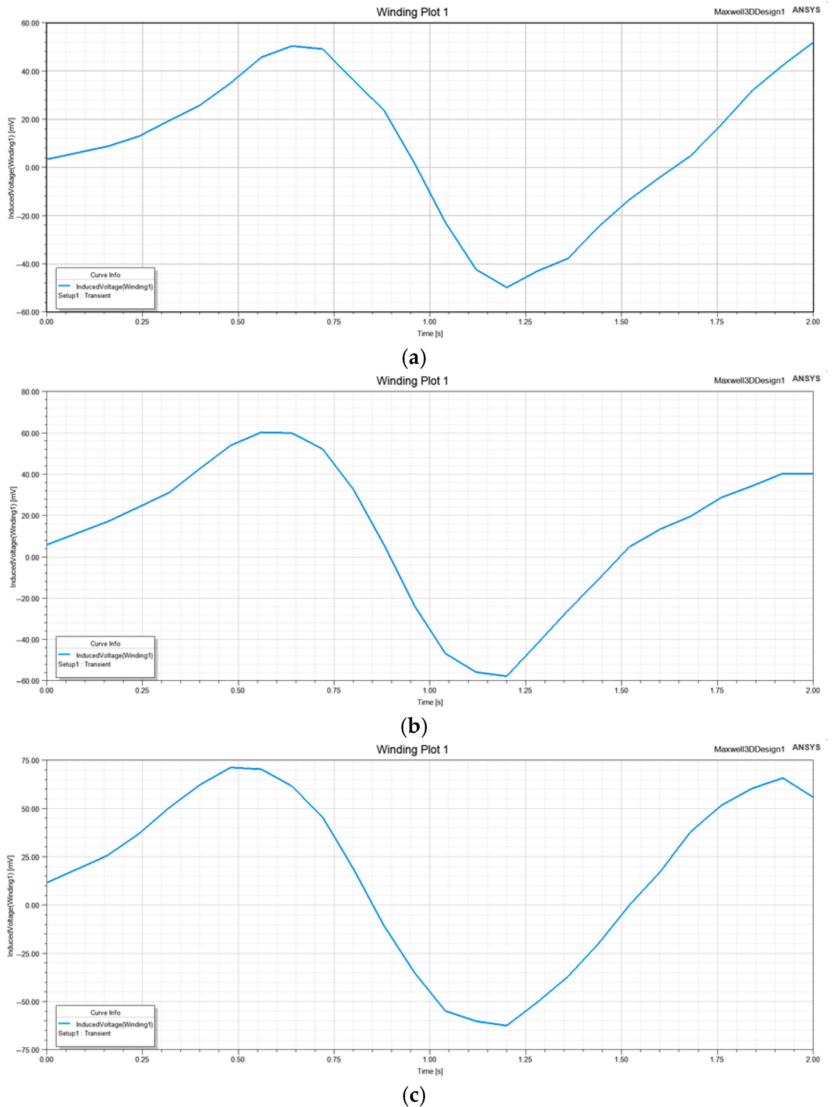
Figure 11 shows the simulation results of the induced EMF waveforms for the cylindrical generator with different PM radius, a fixed air gap length of 3 mm, and a fixed PM height of 13 mm. When the radius of PM is set to 6 mm, 8 mm, 10 mm, and 12 mm, the corresponding EMF amplitudes are 40 mV, 62 mV, 95 mV, and 130 mV, respectively. This indicates that the induced EMF increases with the PM radius.
The induced EMF waveforms for the cylindrical generator with different PM heights are shown in
Figure 12, with a winding inner diameter of 24 mm and a PM width of 16 mm, while keeping the PM’s outer diameter constant. When the height of PM is set to 10 mm, 13 mm, and 16 mm, the corresponding EMF amplitudes are 52 mV, 60 mV, and 70 mV, respectively. Therefore, the induced EMF of the cylindrical generator increases with magnet height. Considering the generator’s overall dimensions and application requirements, the PM of the cylindrical generator is ultimately designed with a radius of 8 mm and a height of 13 mm.
3.3.6. Effect of Rotor Speed on the Induced EMF
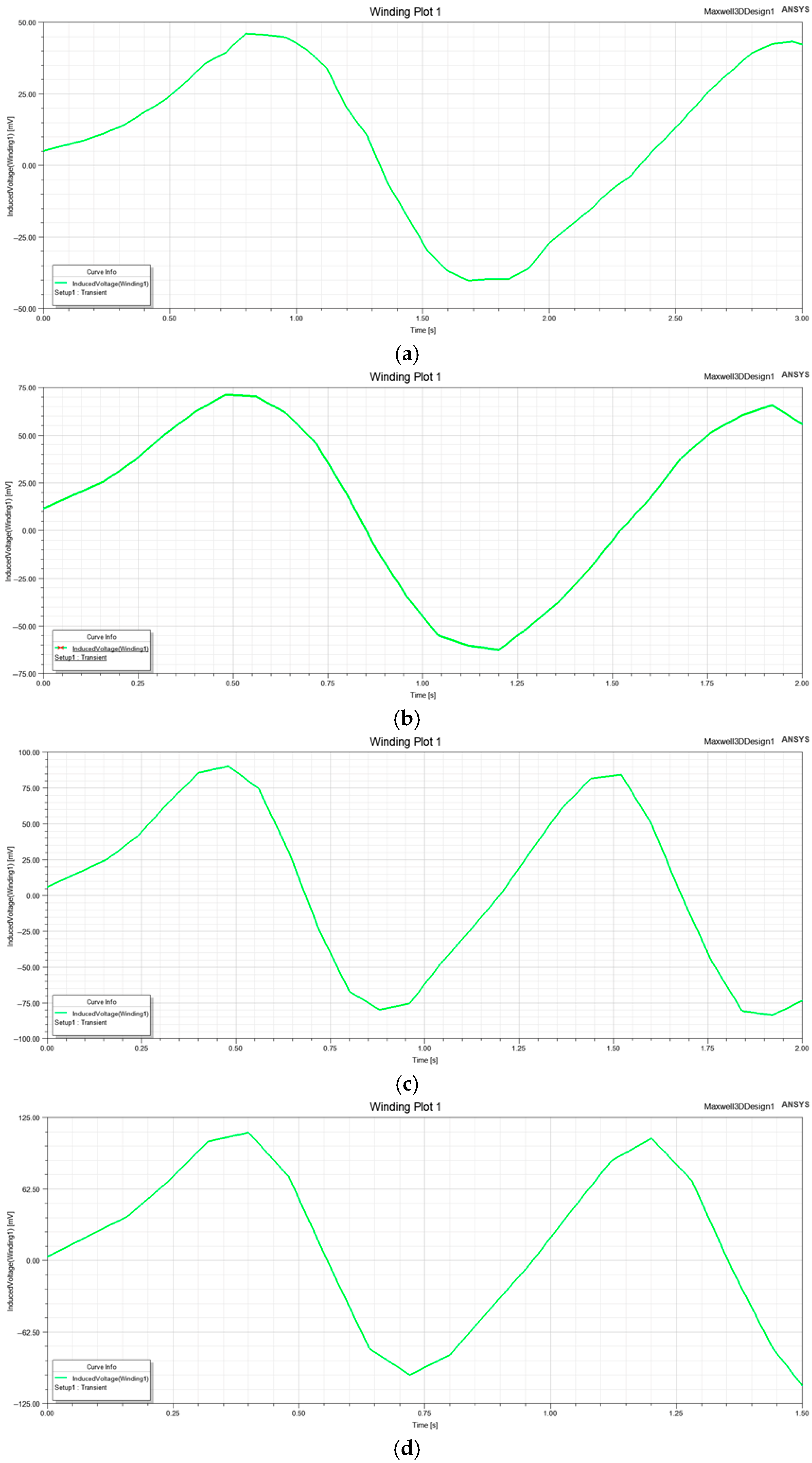
Figure 13 shows the simulation results of the induced EMF generated when the rotor moves at different speeds with constant PM size. When the speed of the rotor is 20 mm/s, 30 mm/s, 40 mm/s, and 50 mm/s, the corresponding induced EMF amplitudes are 45 mV, 70 mV, 90 mV, and 112.5 mV, respectively. This means that the induced EMF of the generator is directly proportional to the speed of the rotor when other conditions are constant.
4. Result
In this section, an experimental platform is established using a swing motor to simulate various wave motions and evaluate the power generation performance of the proposed cylindrical generator. Since wave motion does not follow standard cosine behavior, energy storage circuits are employed to convert the resulting unstable AC into stable and usable DC. In addition, the performance of single capacitors, two capacitors in series, and two capacitors in parallel is analyzed for energy storage under different operating speeds.
4.1. Experimental Setup
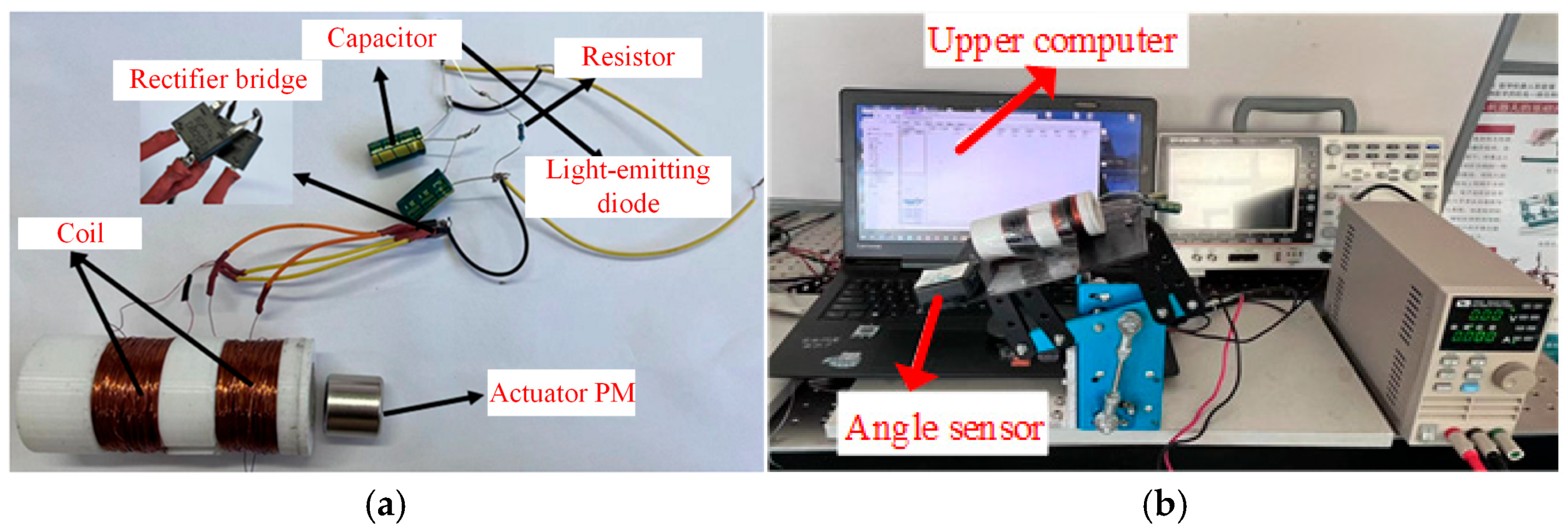
Figure 14a shows the prototype of the cylindrical generator based on Section III. The generator includes two coil windings wound in the same direction using enameled wire to improve magnetic flux cutting and enhance the induced EMF. Each winding has two terminals and is connected in series. The stator is equipped with external slots to accommodate the coils. The series-connected coil outputs are connected to a single-phase fully controlled rectifier bridge. The positive and negative terminals of the rectifier bridge are connected to the positive and negative terminals of the energy storage capacitor, while a resistor and a light-emitting diode are connected in parallel.
The experimental platform is shown in
Figure 14b. The designed cylindrical generator is mounted on a speed-adjustable reciprocating swing motor, controlled by a DC regulated power supply to simulate the oscillatory motion of the amphibious robot under different wave conditions. In addition, an oscilloscope is used to measure the induced EMF of the designed cylindrical generator at different speeds of the swing motor.
4.2. Effect of Actuator Cutting Speed on Induced EMF
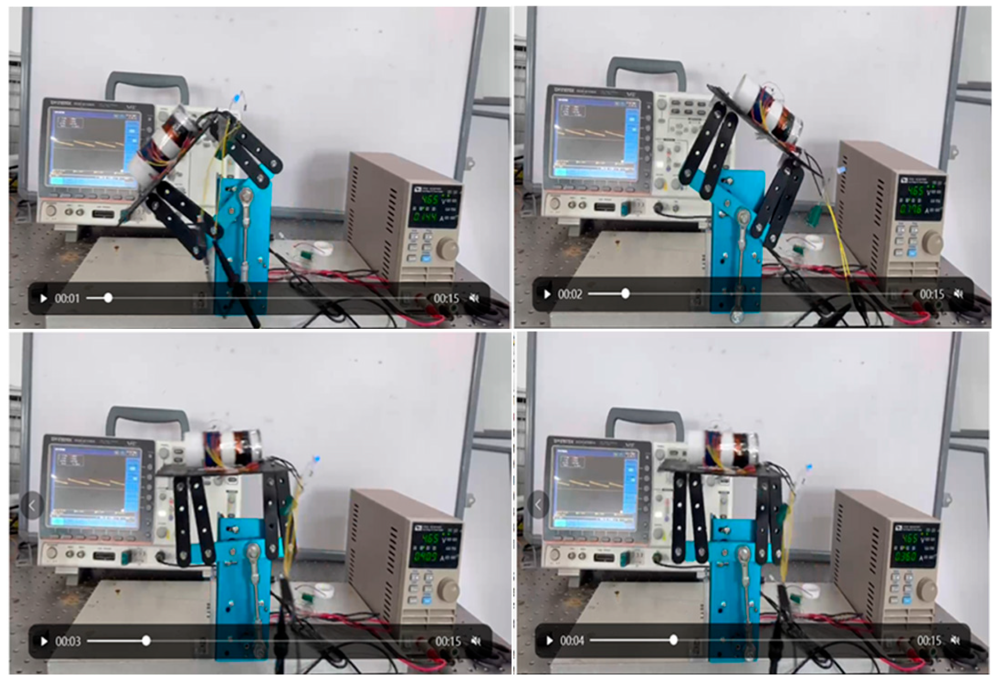
The moving distance
S of the actuator PM in one cycle
T of the cylindrical generator is measured using the Bluetooth angle sensor. Then, the measured distance is transmitted to the upper computer. Therefore, the motion speed of the generator at different voltages of the swing motor can be calculated according to
. The moving process of the designed cylindrical generator is shown in
Figure 15.
Combined with the actual length of the PM and the cylindrical generator, the moving distance of the actuator in one cycle can be calculated as S = 108 mm. The corresponding cutting speeds of the moving cycle T at different voltages are as follows:
- (1)
When the supply voltage is 3.65 V, the period T = 1.5 s and the velocity V1 = 72 mm/s;
- (2)
When the supply voltage is 4.65 V, the period T = 1.2 s and the velocity V2 = 90 mm/s;
- (3)
When the supply voltage is 5.65 V, the period T = 1.0 s and the velocity V3 = 108 mm/s;
- (4)
When the supply voltage is 6.65 V, the period T = 0.8 s and the velocity V4 = 135 mm/s.
Subsequently, the designed cylindrical generator was experimentally tested at the actuator cutting speeds of 72 mm/s, 90 mm/s, 108 mm/s, and 135 mm/s.
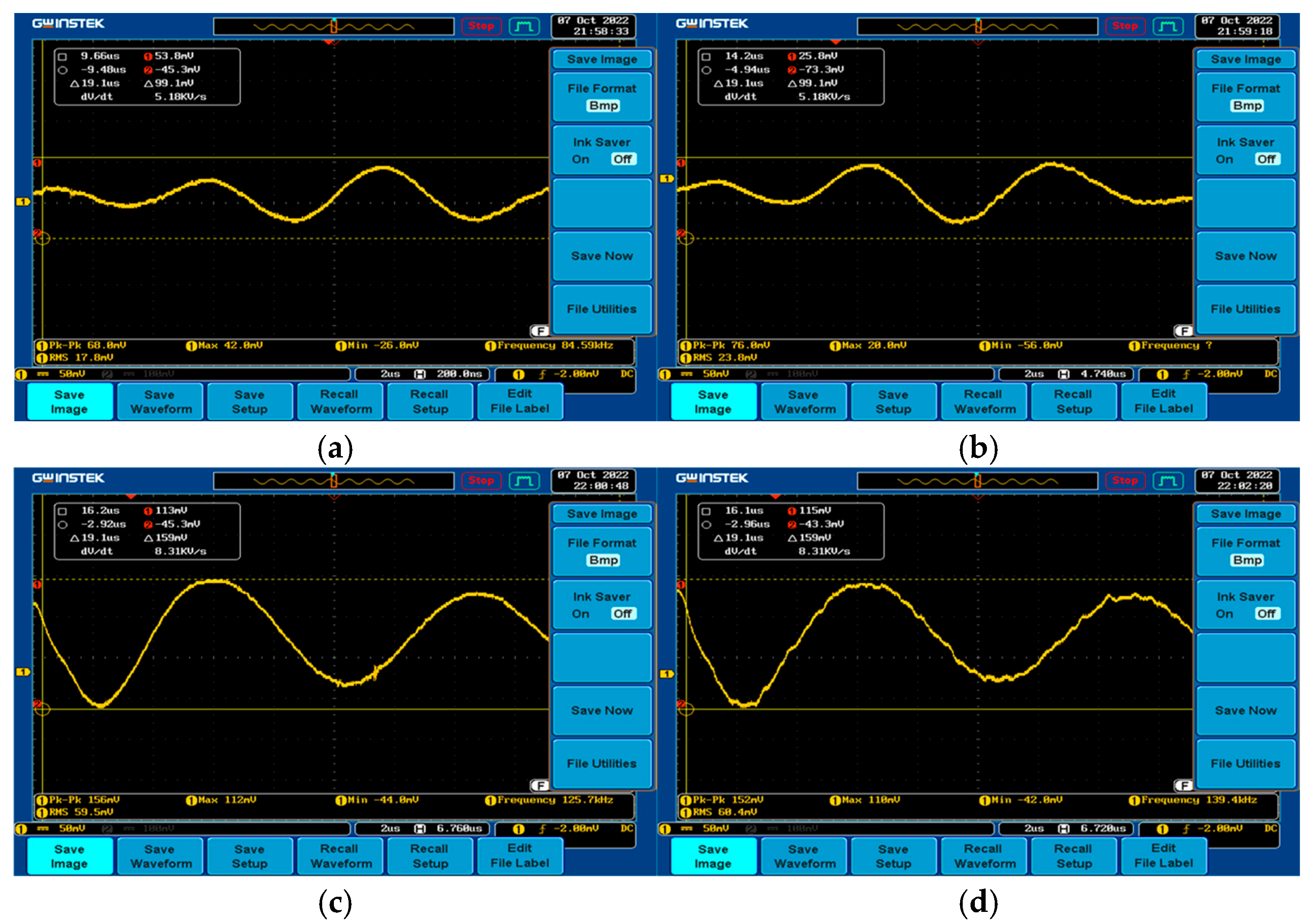
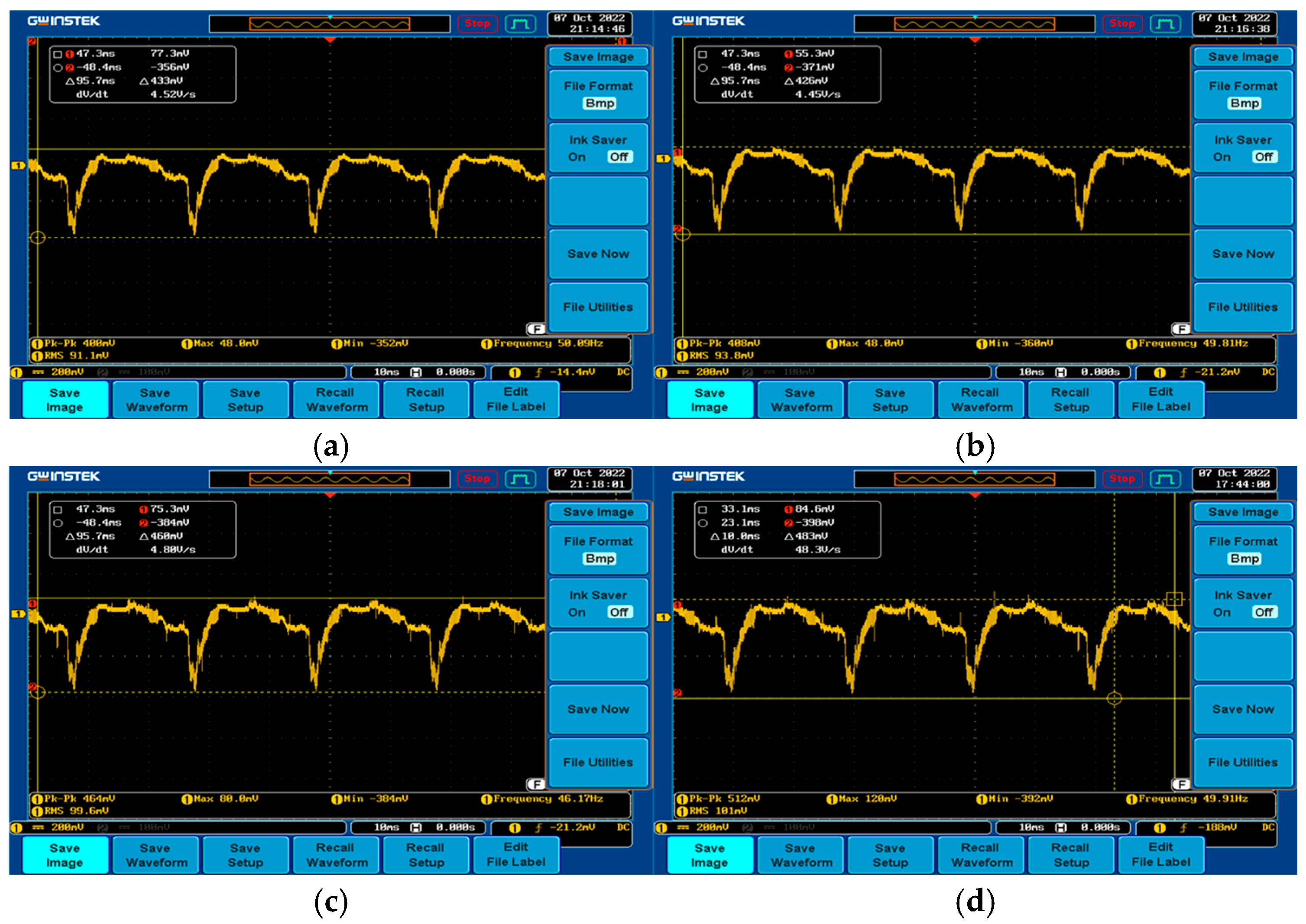
Figure 16 and
Figure 17 compare the induced EMF of the cylindrical generator before and after rectifying the diaspora at different actuator cutting speeds, respectively.
The experimental data show that the valid values of the induced EMF for the cylindrical generator are 17.8 mV, 23.8 mV, 59.5 mV, and 68.4 mV at speeds of 72 mm/s, 90 mm/s, 108 mm/s, and 135 mm/s, respectively. While 91.1 mV, 93.8 mV, 99.6 mV, and 101 mV were obtained after rectification. It can be concluded that before rectification, the induced EMF of the generator increases as the cutting speed of the actuator increases. After rectification, the induced EMF increases due to charge storage in the capacitor of the storage circuit. However, the impact of speed on the induced EMF after rectification is not significant, due to limitations in device size, coil turns, and other factors.
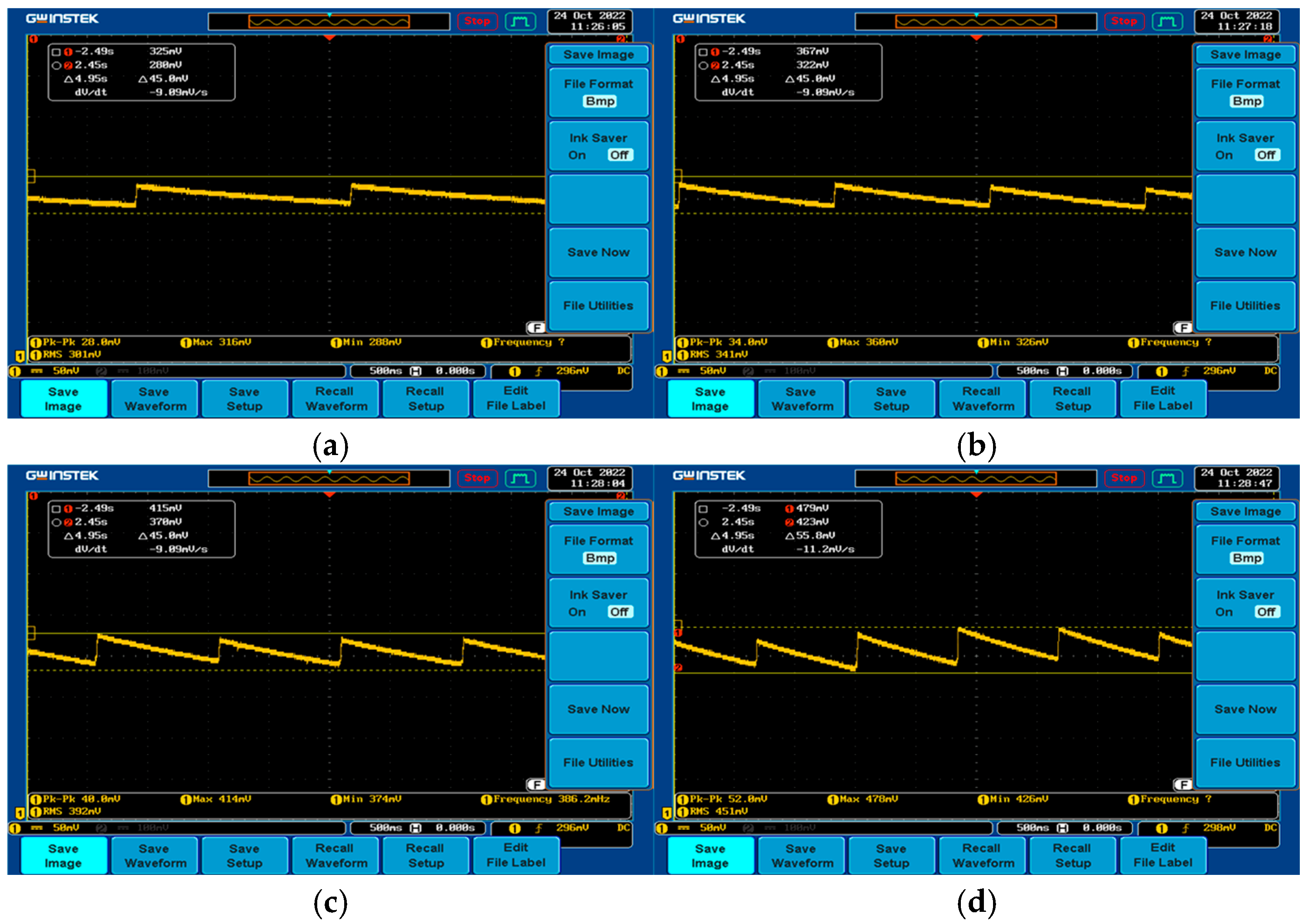
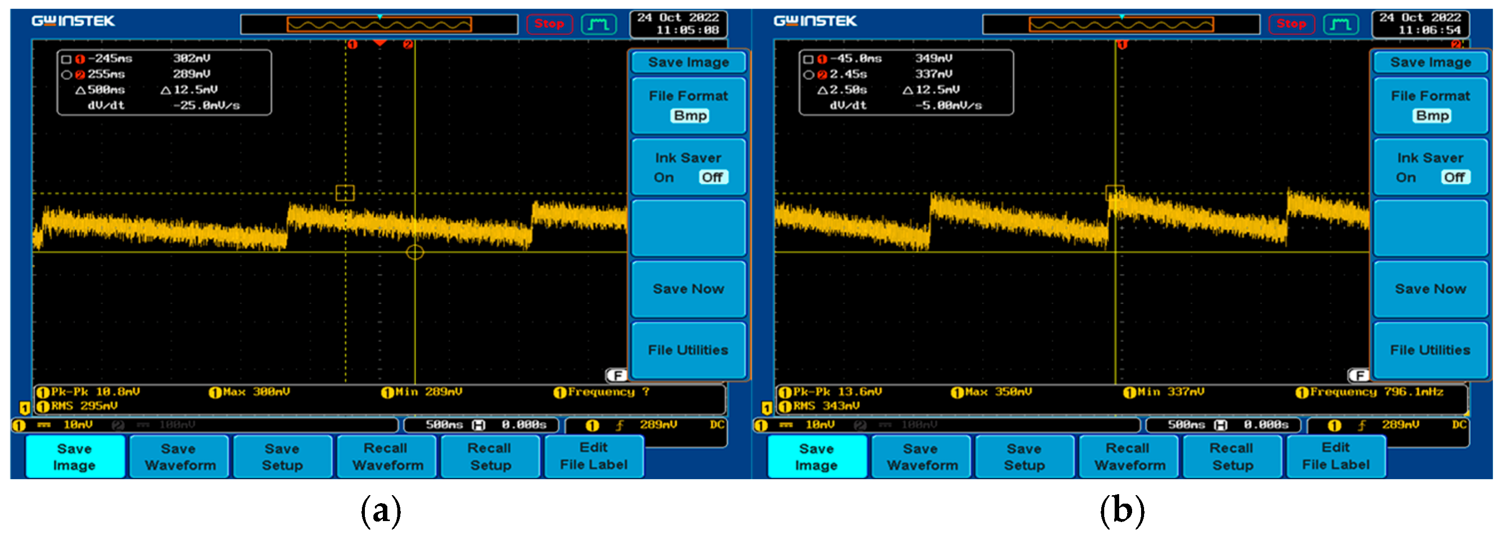
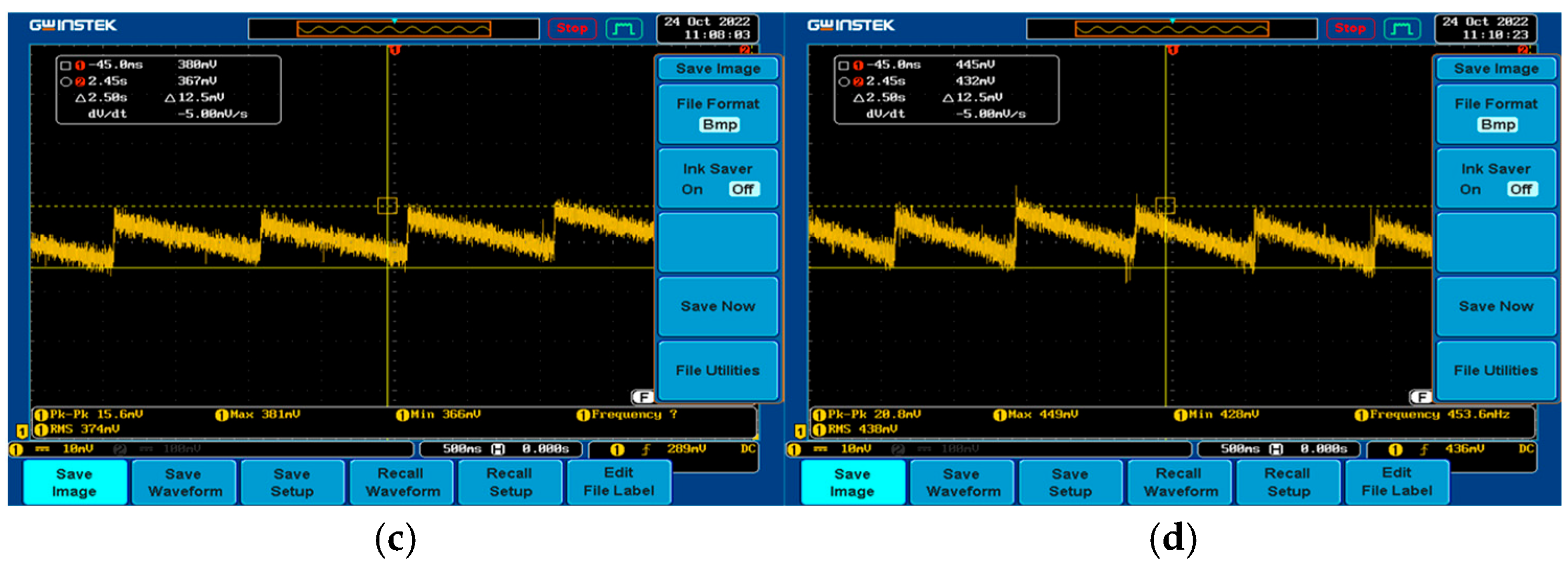
4.3. Analysis of the Induced EMF Generated by the Cylindrical Generator Under Different Capacitance Conditions in the Energy Storage Circuit
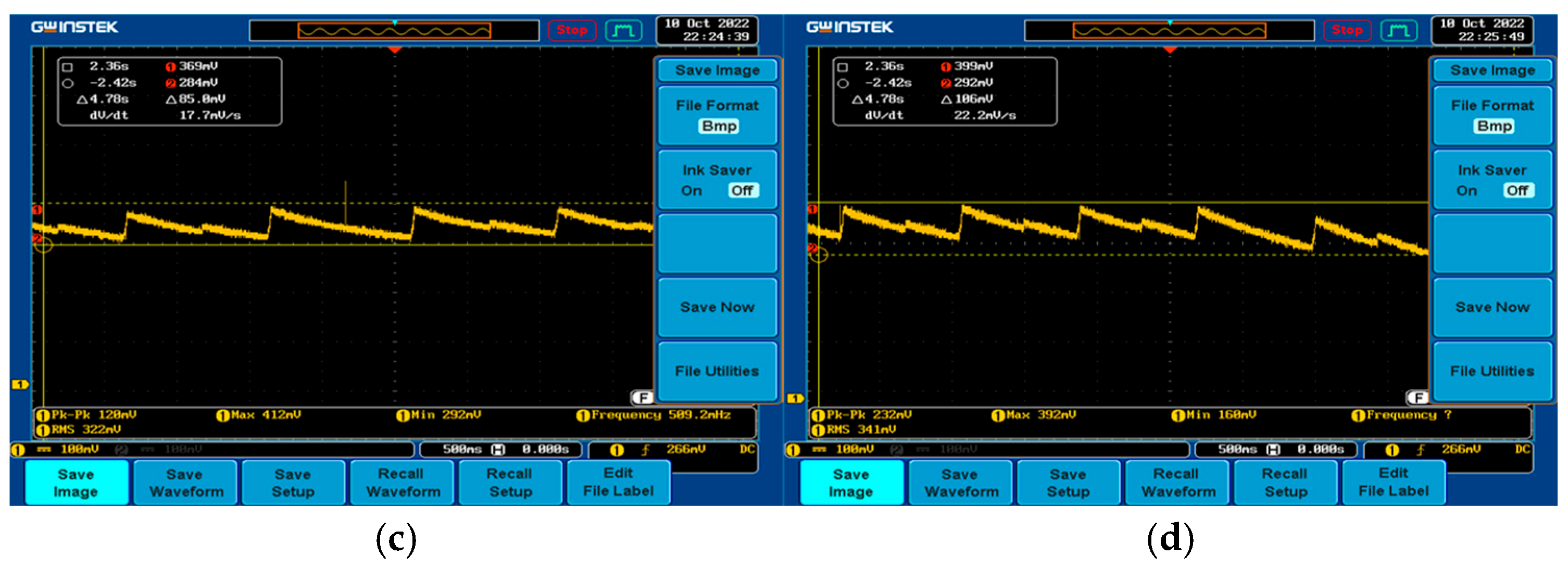
The induced EMF generated by the cylindrical generator at different actuator cutting speeds under single capacitor, two capacitors in series, and two capacitors in parallel is given in
Figure 18,
Figure 19, and
Figure 20, respectively. It can be shown that under the single capacitor condition, the effective values of the induced EMF generated by the generator at cutting speeds of 72 mm/s, 90 mm/s, 108 mm/s, and 135 mm/s are 210 mV, 244 mV, 322 mV, and 341 mV, respectively. Under the condition of two capacitors in series, the effective values are 301 mV, 341 mV, 392 mV, and 451 mV, respectively. Under the condition of two capacitors in parallel, the effective values are 295 mV, 343 mV, 374 mV, and 438 mV, respectively. It can be concluded that the induced EMF of the cylindrical generator increases either in series or in parallel with the capacitor, and the induced EMF is approximately the same under both conditions. Therefore, the induced EMF generated by the cylindrical generator can be increased by connecting the capacitors in series or parallel.
5. Conclusions
Aiming at the problems that the existing amphibious robot has poor endurance, while the power supply system is limited by the installation space, and the driving voltage is high, and the energy utilization rate is low, this paper designed a power supply system for the amphibious robot based on wave energy generation. Referring to the design principle of a linear wave energy generator, the effects of material type, magnetization method, end effect, air gap length, and size of the PM on the induced EMF generated by the cylindrical motor are analyzed. Experiments were conducted to simulate different wave motions and evaluate the power generation performance of the cylindrical generator. However, the actual ocean validation of the cylinder generator is difficult and requires a longer period of trial validation due to the constraints of human and material resources.
Compared to the annular electromagnetic generator proposed in [
34], the cylindrical generator developed in this study is based on the linear permanent magnet generation principle. This configuration facilitates mechanical coupling with the reciprocating limbs of the amphibious robot and simplifies the sealing process, thereby improving the feasibility of integration into amphibious platforms.
Current tests used low-frequency oscillatory motion. However, core losses, including hysteresis and eddy currents, become more significant at continuous or higher-speed operation. This is due to increased magnetic flux variation frequency. The Steinmetz equation [
35] can be used to estimate core loss based on frequency and flux density
In addition, this study aims to validate the power supply subsystem before integration into the amphibious robot. Full integration requires the completion of mechanical, control, and sealing systems, which are still under development. Moreover, quantitatively comparing the system performance before and after integration, focusing on output power, efficiency, and voltage stability in the underwater environment, would require a specialized experimental setup such as a wave tank or ocean deployment, which is beyond the scope of this study. These works are part of the next stage of our research.


