1. Introduction
ASVs have gained substantial interest in recent years for a wide range of applications, including oceanographic surveys, environmental monitoring, maritime logistics, and defense operations [
1,
2,
3]. Despite significant progress in ASV development, achieving precise and robust trajectory tracking under dynamic and uncertain ocean environments remains a key technical challenge. Ocean disturbances such as waves, wind, and currents introduce nonlinear effects and unpredictable dynamics that conventional control systems often struggle to compensate for effectively [
4].
Classical control methods like PID controllers are simple and widely used but lack the ability to handle nonlinearities and time-varying disturbances [
5]. To address these shortcomings, nonlinear control techniques such as sliding mode control (SMC) [
6], backstepping [
7], and adaptive control methods [
8] have been introduced. Although these methods improve robustness, they often require accurate system models and may be sensitive to unmodeled dynamics or introduce chattering effects [
9,
10].
To overcome such limitations, fuzzy logic-based methods have emerged as promising alternatives. Fuzzy control (FC) inherently handles nonlinearities and uncertainties without requiring precise modeling [
11]. Its adaptive counterpart, adaptive fuzzy control (AFC), enhances system performance through real-time parameter tuning [
12,
13]. Hybrid approaches have further advanced these capabilities by integrating fuzzy systems with other techniques, such as SMC [
14], neural networks [
15], and disturbance observers [
16]. However, many of these controllers either lack formal Lyapunov-based stability proofs or struggle to maintain performance under strong external disturbances [
17,
18].
In the maritime domain, fuzzy control has been extensively applied to trajectory tracking problems of ASVs. Zhang et al. [
19] proposed a fuzzy optimal tracking controller with prescribed-time convergence for ASVs. Data-driven techniques such as neural networks [
20] and reinforcement learning [
21] have further enhanced the adaptability of control systems in uncertain marine environments. Despite these advancements, ensuring high-precision tracking, smooth control signals, and robust performance under persistent oceanic disturbances remains an ongoing challenge.
Building upon the prior literature, this paper proposes a robust adaptive fuzzy control (RAFC) scheme for trajectory tracking of ASVs subjected to multiple perturbations. The proposed framework integrates a nonlinear controller to cancel the nonlinear components of the error dynamics and an adaptive fuzzy estimator to approximate and reject the effects of environmental disturbances. This unified approach provides a balance between accuracy and robustness.
Recent advancements in adaptive fuzzy control have demonstrated its potential for ASVs. Lin et al. [
22] proposed an adaptive fuzzy output feedback controller aimed at the stabilization of underactuated vessels under model uncertainties. However, their approach did not address trajectory tracking or full-state dynamics. Hu et al. [
23] developed a fuzzy logic-based collision avoidance system, which focused on real-time reactive maneuvers but lacked adaptive trajectory tracking capability. Zhang et al. [
24] introduced an adaptive fuzzy control framework for fast and accurate trajectory tracking without disturbance observers. While effective, their method involved a more complex fuzzy rule structure and did not emphasize robustness under large parametric uncertainties.
Representative works on adaptive fuzzy and robust nonlinear control have provided rigorous robustness analyses. In [
25], a dynamic controller enabled ground vehicle tracking under uncertainties in tire parameters and lateral wind disturbances, achieving parameter and disturbance estimation. Similarly, [
26] proposed a nonlinear adaptive approach handling system nonlinearities and unknown friction, offering strong robustness proofs. These studies exemplify robust control design under significant uncertainties.
In contrast, the proposed RAFC method adopts a simplified Takagi–Sugeno fuzzy structure combined with a Lyapunov-based adaptive law to handle ocean-environmental disturbances. It ensures smooth velocity tracking, reduced control chattering, and energy-efficient performance, making it well-suited for real-time embedded ASV applications. These features position RAFC as a robust and practical alternative to existing fuzzy control approaches.
The primary objective of this study is to develop an RAFC strategy for ASVs to achieve accurate trajectory tracking despite the presence of significant ocean environmental disturbances. This approach aims to eliminate reliance on precise system modeling by embedding a fuzzy logic inference mechanism into a nonlinear control framework. Additionally, the adaptation law, developed based on Lyapunov stability theory, guarantees boundedness of the tracking error, while the fuzzy inference mechanism contributes to mitigating the effects of external disturbances.
The novelty of this research lies in the development of an RAFC framework that tightly integrates an adaptive fuzzy inference mechanism with a nonlinear robust control structure, guided by a Lyapunov-based design methodology. Distinct from traditional FC or AFC methods, the proposed RAFC architecture enables real-time estimation and compensation of unknown external disturbances without requiring prior system modeling or disturbance profiles. By continuously adjusting fuzzy parameters based on the observed trajectory tracking error and dynamic system responses, the controller achieves enhanced adaptability and resilience in complex marine environments. This dynamic compensation strategy not only improves disturbance rejection and tracking accuracy but also mitigates control signal chattering, ultimately guaranteeing uniformly ultimately bounded (UUB) stability across varying operational scenarios.
The key contributions of this study are fourfold and reflect both theoretical innovation and practical relevance:
First, a novel RAFC architecture is systematically developed for ASVs operating in marine environments characterized by nonlinear dynamics and unpredictable external disturbances. Unlike conventional model-based or static fuzzy control methods, the proposed approach requires no prior knowledge of system models or disturbance bounds, making it highly suitable for real-world deployment.
Second, the control design introduces an adaptive fuzzy inference structure that dynamically tunes the fuzzy parameters online in response to tracking errors and environmental changes. This mechanism enhances the controller’s flexibility and robustness without incurring the instability risks often associated with high-gain or switching-type designs.
Third, a comprehensive Lyapunov-based analysis is rigorously carried out to guarantee closed-loop stability and ensure that all system signals are UUB. This provides a mathematically solid foundation for real-time application in uncertain operating conditions.
Fourth, the effectiveness and robustness of the proposed RAFC controller are validated through extensive simulations involving two distinct trajectory scenarios (circular and square paths) under ocean-environmental disturbances. The results demonstrate superior tracking precision, reduced control chattering, and improved energy efficiency when compared to traditional non-adaptive controllers, confirming the proposed method’s significant advantages in terms of performance and reliability.
The remainder of this paper is structured as follows:
Section 2 presents the dynamic model of the ASV.
Section 3 details the proposed RAFC design and stability analysis.
Section 4 provides simulation results and comparative performance evaluations. Finally,
Section 5 concludes the study and outlines future research directions.
2. Model of the Controlled ASV
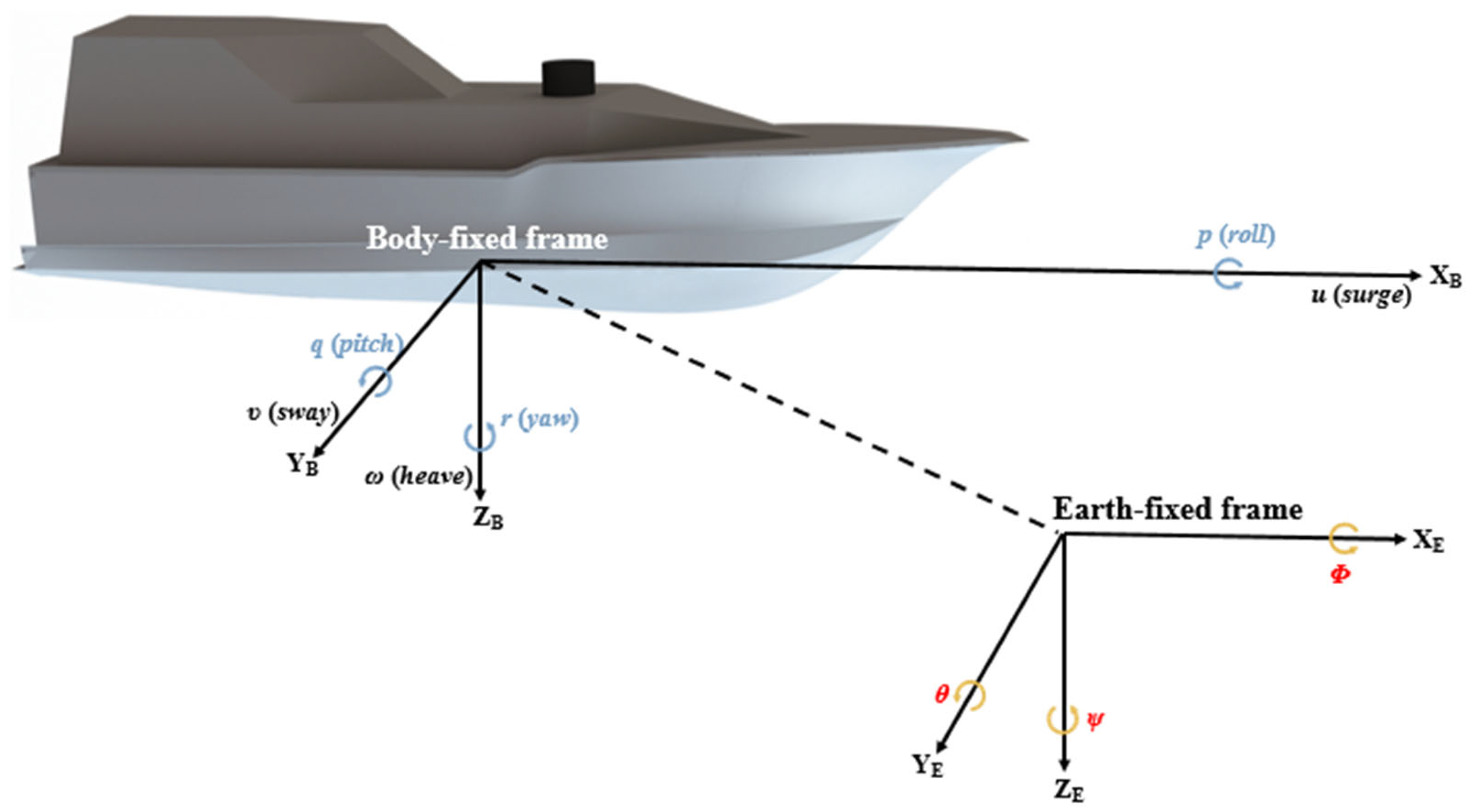
The six degrees of freedom (6-DOF) motion of an ASV encompasses both translational and rotational dynamics in three-dimensional space. Translational motions include surge, sway, and heave, which occur along the body-fixed X
B-, Y
B-, and Z
B-axes, respectively, and are represented by linear velocities
u,
v, and
w. Rotational motions—roll, pitch, and yaw—occur about the same axes and are described by angular velocities
p,
q, and
r. These velocity components are defined in the body-fixed frame. In contrast, the corresponding global positions (
x,
y,
z) and orientations (
ϕ,
θ,
ψ) are described in the Earth-fixed frame. A detailed correspondence between each degree of freedom, its physical interpretation, and the associated variables in both frames is summarized in
Figure 1 and
Table 1 [
27].
Since motions of heave, pitch, and roll of ASVs are not controllable in practice, the 6-DOF model of ASVs is remodeled as a 3-DOF controllable dynamics in Earth-frame coordinate as follows [
28]:
where
In this investigation, stands for the inertia mass, denotes the Coriolis and centripetal matrix, is the damping matrix, represents the control command, and is the overall ocean-environmental disturbances induced by random wave (τwave), wind (τwind), and current (τcurrent) in Earth-fixed coordinate frame, respectively. denotes the real-time position (X and Y) and heading angle () of ASV in Earth-frame coordinate, and denotes the linear velocities in the surge (u) and sway (v) directions, as well as the angular velocity in yaw (r), all expressed in the body-fixed coordinate frame.
3. Robust Adaptive Fuzzy Control Design for ASV Trajectory Tracking Problem
In this section, a nonlinear control scheme, referred to as the RAFC, is developed to address the trajectory tracking problem of ASVs operating under multiple disturbances, such as wind, wave, and current. This approach integrates an RAFC structure to effectively mitigate marine environmental perturbations commonly encountered in the ocean. By utilizing a fuzzy logic system, the controller improves the approximation capability for unknown disturbances, while the adaptive mechanism continuously adjusts control parameters to enhance robustness and maintain consistently precise tracking performance. The proposed method further simplifies the nonlinear control law, enabling more precise and efficient trajectory tracking.
To rigorously validate the stability and convergence of the proposed RAFC strategy, a Lyapunov-based stability analysis is performed. The analysis confirms that the closed-loop system ensures the boundedness of all internal signals and guarantees the asymptotic convergence of tracking errors in the presence of multiple disturbances. The subsequent sections provide a comprehensive formulation of the RAFC, including the construction of the fuzzy inference system, design of adaptive laws, synthesis of the control law, and the corresponding Lyapunov-based stability proof, which collectively establish the theoretical basis for simulation-based verification.
3.1. Robust Adaptive Fuzzy Control Law Design
In this section, a robust adaptive fuzzy control law is employed as a foundational component to manage the nonlinear dynamics of the controlled ASV for trajectory tracking and feasibility verification under multiple disturbances. This control structure serves as the baseline framework upon which the proposed robust adaptive fuzzy control strategy is built. By applying the complex nonlinear behavior of the ASV dynamics, it is transformed into a linearized form, facilitating a more straightforward control design process.
To assess the tracking performance, the tracking error is defined as the difference between the desired trajectory, denoted as
, and the actual position and orientation of the ASV, denoted as
, as presented in Equation (4). This error formulation provides the analytical foundation for evaluating the controller’s effectiveness and plays a critical role in the subsequent Lyapunov-based stability analysis of the closed-loop disturbed system.
where
is the desired position, and
is the desired heading angle.
By taking the first and second time derivatives of the tracking error equation defined in (4), the dynamic evolution of the tracking error can be explicitly characterized. These derivations, presented in Equations (5) and (6), respectively, form the basis for the subsequent control law design, enabling the development of a nonlinear controller that effectively compensates for external disturbances and ensures precise trajectory tracking performance.
To facilitate subsequent analysis, Equation (1) is reformulated as Equation (7) and then substituted into Equation (6). This yields the trajectory tracking error dynamics expressed in Equation (8), which characterizes the relationship between the desired trajectory and the controlled ASV as follows:
and
Based on the derived trajectory tracking error dynamics, a nonlinear control law
is applicably designed as follows to ensure robust compensation for system nonlinearities and ocean disturbances, thereby achieving accurate trajectory tracking for the ASV:
where
is
By substituting Equation (9) into Equation (8), a trajectory tracking error dynamics is obtained via using a nonlinearly transformed formulation. This transformation facilitates the subsequent control design and stability analysis and can be expressed as follows:
In the proposed control framework,
is designed as a robust adaptive fuzzy compensator to accurately estimate and mitigate the effects of random ocean environmental disturbances denoted by
. Furthermore, the control gain matrices
and
are introduced to enhance the system’s convergence speed and robustness. The parameters
,
, and
are defined as follows:
However, in real-world maritime environments, ocean disturbances are inevitable and often uncertain, which makes it difficult to ensure that the tracking error converges to zero. Therefore, it is crucial to explicitly consider such ocean disturbances in the control design. To effectively cope with this issue, a robust adaptive fuzzy estimator is further developed in this study to enhance control performance and ensure accurate trajectory tracking under the effects of ocean disturbances. The detailed design of the proposed robust adaptive fuzzy estimator is presented in the following section.
3.2. Robust Adaptive Fuzzy Estimator Design
To ensure accurate trajectory tracking performance in the presence of ocean environmental disturbances, a robust adaptive fuzzy estimator strategy is proposed in this section. By reformulating the system dynamics, the original nonlinear system is transformed into error dynamics as expressed in Equation (13). An adaptive fuzzy inference mechanism is then integrated into the control law to approximate the unknown ocean disturbances in real time. The overall control framework guarantees both stability and robustness, even under significant system perturbations. The detailed design procedure is outlined as follows.
To address the unknown total ocean disturbance
, an adaptive fuzzy-based estimator
is developed for the purpose of real-time approximation. This estimator employs a set of fuzzy inference rules driven by the tracking error dynamics, allowing it to continuously learn and approximate for complex environmental and model-related perturbations. The structure of the estimator is formulated as follows:
In this context,
denotes the parameter matrix associated with the fuzzy basis functions, while
represents the adaptive parameter vector governed by the update law. Their mathematical definitions are provided as follows:
The number n of fuzzy If–Then rules is adjustable and can be selected based on the desired approximation accuracy. However, increasing n inevitably leads to higher computational complexity during implementation, which necessitates a trade-off between estimation precision and real-time performance.
Moreover, the optimal parameter vector
, determined through the adaptive update law, is defined as follows to guide the parameter adjustment process and ensure accurate disturbance approximation.
denotes the Euclidean norm, whereas represents the set of all possible values of within the considered disturbance bounds.
As a result, the optimal estimate
can be formulated as a function of the optimal parameter vector
, as defined in Equation (23), and the parameter matrix
, introduced in Equation (18), as follows:
The approximation error
is defined as the difference between the total disturbance
, as described in Equation (16), and the optimal estimation
, as given in Equation (24), and can be expressed as follows:
Additionally, the parameter approximation error
is defined as the deviation between the adaptive parameter
, specified in Equation (23), and its optimal counterpart
, also defined in Equation (23), and can be expressed as follows:
By substituting Equations (17), (24)–(26) into the error dynamics
defined in Equation (13), the following expression is obtained:
3.3. Lyapunov Stable Analysis
To rigorously demonstrate the stability of the proposed robust adaptive fuzzy control system under the presence of ocean disturbances, a Lyapunov-based analysis is conducted based on the nonlinear second-order tracking error dynamics and the fuzzy approximation structure. This analysis establishes a theoretical foundation for the convergence characteristics of the closed-loop system.
To analyze the stability, the following Lyapunov function candidate is proposed:
where
is a symmetric positive-definite adaptation gain matrix.
Differentiating (28) with respect to time yields
Substituting the error dynamics from (27) into (29) leads to
Using the identity
, the above expression simplifies to
Applying the adaptation law,
then
Substituting (34) into (32) gives
Assuming that
, where
is a known constant representing the upper bound of the residual fuzzy approximation error, the upper bound of the Lyapunov derivative is
This expression implies that
holds whenever
Therefore, it can be concluded that all signals in the closed-loop system are uniformly bounded even under effects of multiple disturbances. With respect to the number of fuzzy rules and the learning structure of the fuzzy system,
must be a calculable and theoretical upper bound [
29]. Furthermore, the tracking error
and its derivative converge to a compact neighborhood around the origin whose size is determined by the upper bound
and the gain matrix
. As a result, the proposed control strategy ensures uniform ultimate boundedness (UUB) of the system states under bounded approximation error and ocean disturbances, thereby ensuring reliable and accurate trajectory tracking.
3.4. Research Methodology and System Framework
The overall control methodology employed in this study is illustrated in
Figure 2, which presents a closed-loop framework for robust trajectory tracking of an ASV under uncertain marine environments. The system begins with a desired trajectory (DT) generator that defines the reference states for position and heading. These references are continuously compared with the actual ASV states to compute the tracking error, which serves as the primary feedback signal for the control system.
The control law is designed based on a robust adaptive framework that compensates for system nonlinearities and external disturbances. To approximate the unknown dynamics in real time, a fuzzy logic system is integrated within the controller. The fuzzy approximator takes the tracking error as input and estimates the nonlinear uncertainties through adaptive fuzzy basis functions. These estimates are then incorporated into the control input to enhance tracking performance.
An adaptive law governs the online updating of the fuzzy system parameters, ensuring convergence and stability of the closed-loop system. The total control input, comprising both the adaptive control law and the fuzzy approximation, is applied to the ASV dynamics along with environmental disturbances such as wind, wave, and current. The resulting system response is fed back to complete the control loop.
This integrated structure enables the controller to achieve accurate trajectory tracking while maintaining robustness against external perturbations, forming the foundation of the proposed robust adaptive fuzzy control strategy.
Remark 1. Handling of external disturbances:
This study focuses on addressing external environmental disturbances that affect ASVs during trajectory tracking. These disturbances—including wind, wave action, and ocean currents—are inherently unpredictable and difficult to model accurately. The proposed RAFC scheme integrates a fuzzy inference system with adaptive parameter tuning, enabling the controller to approximate unknown nonlinear disturbance effects in real time without requiring explicit disturbance modeling. The robust structure of the control law is designed to compensate for the impact of these disturbances by dynamically adjusting control inputs based on the estimated error and system response. The stability of the closed-loop system under such time-varying disturbances is rigorously proven through Lyapunov theory, ensuring that all system signals remain bounded and that the tracking error converges asymptotically.
Remark 2. Advantages and limitations of the proposed control scheme:
The proposed RAFC method offers several notable advantages. It does not rely on an accurate mathematical model of the ASV, making it suitable for systems operating in dynamic and uncertain marine environments. The fuzzy logic component provides a flexible and interpretable means of capturing complex system behavior and disturbance effects, while the adaptive mechanism enables continuous online adjustment to maintain performance under varying operating conditions. However, there are some limitations. The fuzzy controller requires real-time updating of parameters, which increases computational demand, potentially limiting its applicability on resource-constrained embedded platforms. Furthermore, the design of the fuzzy rule base and membership functions, as well as the tuning of adaptive gains, relies on engineering experience and may influence the transient performance if not carefully selected.
Despite these challenges, the simulation results demonstrate that the proposed approach achieves stable and accurate trajectory tracking even in the presence of substantial external disturbances, supporting its practicality for ASV control applications.
4. Discussion of Simulation Results
This section presents the simulation studies conducted to evaluate the trajectory tracking performance of both the feedback linearization control (FLC) strategy and the proposed RAFC method. The simulations were implemented using MATLAB R2024b and involved two distinct DT configurations: a circular trajectory and a square trajectory. These two representative scenarios were selected to rigorously assess the effectiveness, robustness, and adaptability of the control schemes under different geometric constraints and maneuvering demands. The subsequent subsections provide comprehensive details regarding the ASV model parameters, the design and structure of the fuzzy logic system including its membership functions, and an in-depth analysis of the simulation results. The comparative evaluation aims to highlight the superior performance of the RAFC in ensuring accurate trajectory tracking and maintaining robustness against multiple ocean disturbances.
4.1. ASV Configuration and Control Parameters
This section outlines the simulation settings, including the configuration parameters of the ASV and the assumed environmental disturbance conditions. The physical and hydrodynamic parameters of the controlled ASV illustrated in
Figure 1 are systematically specified, with their numerical values summarized in
Table 2. These parameters reflect realistic characteristics of typical marine vessels and form the foundation for accurate modeling of the ASV’s dynamic behavior.
In addition to the ASV configuration, a set of predefined ocean disturbance parameters is introduced to emulate realistic operational conditions. These include external forces such as wave-induced forces, wind loads, and current effects, all of which are critical to assessing controller robustness in maritime environments [
28]. The assumed values are selected based on common conditions encountered in littoral and offshore scenarios and are essential for validating the performance and disturbance rejection capability of the control strategies under investigation.
The defined simulation setup is employed to examine and compare the trajectory tracking effectiveness of both the FLC and the proposed RAFC. The validation is carried out under two representative trajectory scenarios—circular and square trajectories—designed to challenge the system with both continuous curvature and abrupt directional changes. These conditions enable a comprehensive evaluation of each controller’s ability to maintain accuracy and stability under practical constraints.
The control gain parameters associated with the proposed RAFC are carefully selected to ensure system stability and high tracking performance under such uncertain and dynamic environments. The specific parameter values used in the RAFC design are summarized below and remain consistent across all simulation scenarios to facilitate a fair and consistent comparison with the FLC method.
4.2. Adaptive Fuzzy Logic Structure and Membership Function Design
In this study, Gaussian membership functions are adopted within the fuzzy logic system owing to their advantageous mathematical characteristics and suitability for managing nonlinearities and environmental disturbances in marine control applications. Their inherent smoothness and differentiability make Gaussian functions particularly well-suited for fuzzy inference mechanisms, as they facilitate seamless transitions and improve the precision of rule activation, which is critical in the design of an RAFC.
One of the key advantages of Gaussian membership functions is their global support, allowing them to provide consistent approximation performance across the entire input domain. This property enhances the system’s ability to maintain stable control responses under varying environmental conditions, such as wave, wind, and current disturbances. Furthermore, their smooth gradients contribute to reduced chattering and improved transient response, which are essential for achieving high-fidelity tracking and ensuring closed-loop stability in systems with uncertain dynamics.
By employing Gaussian membership functions, the RAFC system gains improved robustness and adaptability, enabling it to effectively approximate ocean perturbations that are prevalent in real-world ASV operations. The precise mathematical formulations of the membership functions used in this study are presented in Equation (42) through (48) [
30].
where
for
i = 1, 2, 3 and
j = 1, 2, 3, 4, 5, 6, where
,
,
,
,
,
represent the centers of each membership function that will be utilized for parameter adjustment. Additionally, the fuzzy logic system outputs
are determined by seven fuzzy rules, corresponding to six state variables. The fuzzy rules are explicitly defined by the following statements [
30]. For
i = 1, 2, 3 and
j = 1, 2, 3, 4, 5, 6, the values
,
,
,
,
,
denote the centers of the Gaussian membership functions, which are adjusted online to enhance control performance. The fuzzy logic system generates outputs based on seven inference rules constructed from six key state variables. The rule set is defined as follows.
for
i = 1, 2, 3.
The fuzzy parameter matrix
and the adaptive vector
are defined as follows.
where
for
i = 1, 2, 3.
The use of Gaussian membership functions significantly contributes to the robustness and precision of the proposed control strategy. Their inherent smoothness and differentiability enable accurate fuzzy inference, which is particularly effective in managing nonlinear dynamics and external environmental disturbances. The symmetrical distribution of the membership functions ensures complete input space coverage and enhances control granularity. This design minimizes chattering and improves transient performance by generating smooth and continuous control signals. To ensure consistency across all evaluations, the same Gaussian membership functions and fuzzy rules are applied throughout the simulation studies.
4.3. Simulation Results and Performance Evaluation
To validate and compare the performance of the SMC, the FLC, and the proposed RAFC strategy, two representative simulation scenarios were designed. These scenarios involve distinct DTs—one circular and one square trajectory—selected to evaluate controller robustness and tracking accuracy under different maneuvering conditions. The specific configurations of the desired waypoints and the initial states of the ASV for each scenario are detailed in subsequent sections. A detailed performance comparison is provided for the three control methods, clearly illustrating their differences in tracking precision and robustness against external disturbances. The analysis of these results underscores the superior tracking performance and enhanced robustness of the RAFC relative to the SMC and FLC approach.
4.3.1. Scenario 1 (Circular Trajectory)
In this simulation scenario, the DT is constructed using five predefined waypoints, as listed in
Table 3. Based on these waypoints, a continuous and smooth circular trajectory is generated through cubic spline interpolation. The objective is to evaluate and compare the tracking performance of the SMC, the FLC, and the proposed RAFC under a curved motion profile. The circular trajectory introduces continuous directional variation, thereby testing the controllers’ ability to maintain accuracy and stability during smooth turning maneuvers. The initial conditions of the controlled ASV for this scenario are summarized in
Table 4.
To evaluate the practical effectiveness of the proposed control strategies under realistic maritime operating conditions, simulation tests were conducted using a circular desired trajectory. Three control schemes were evaluated: the SMC, the FLC, and the proposed RAFC.
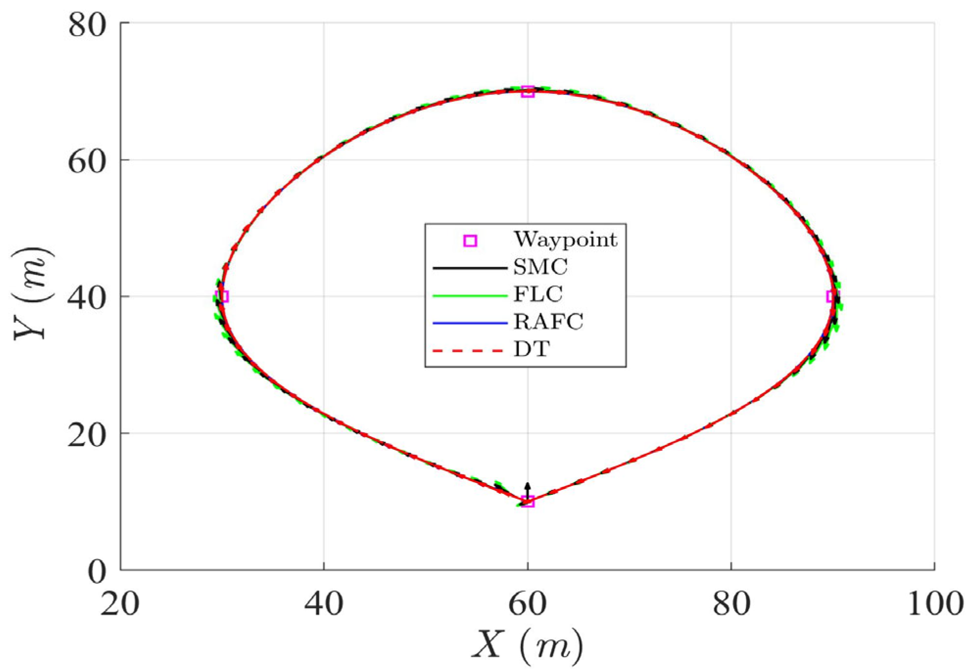
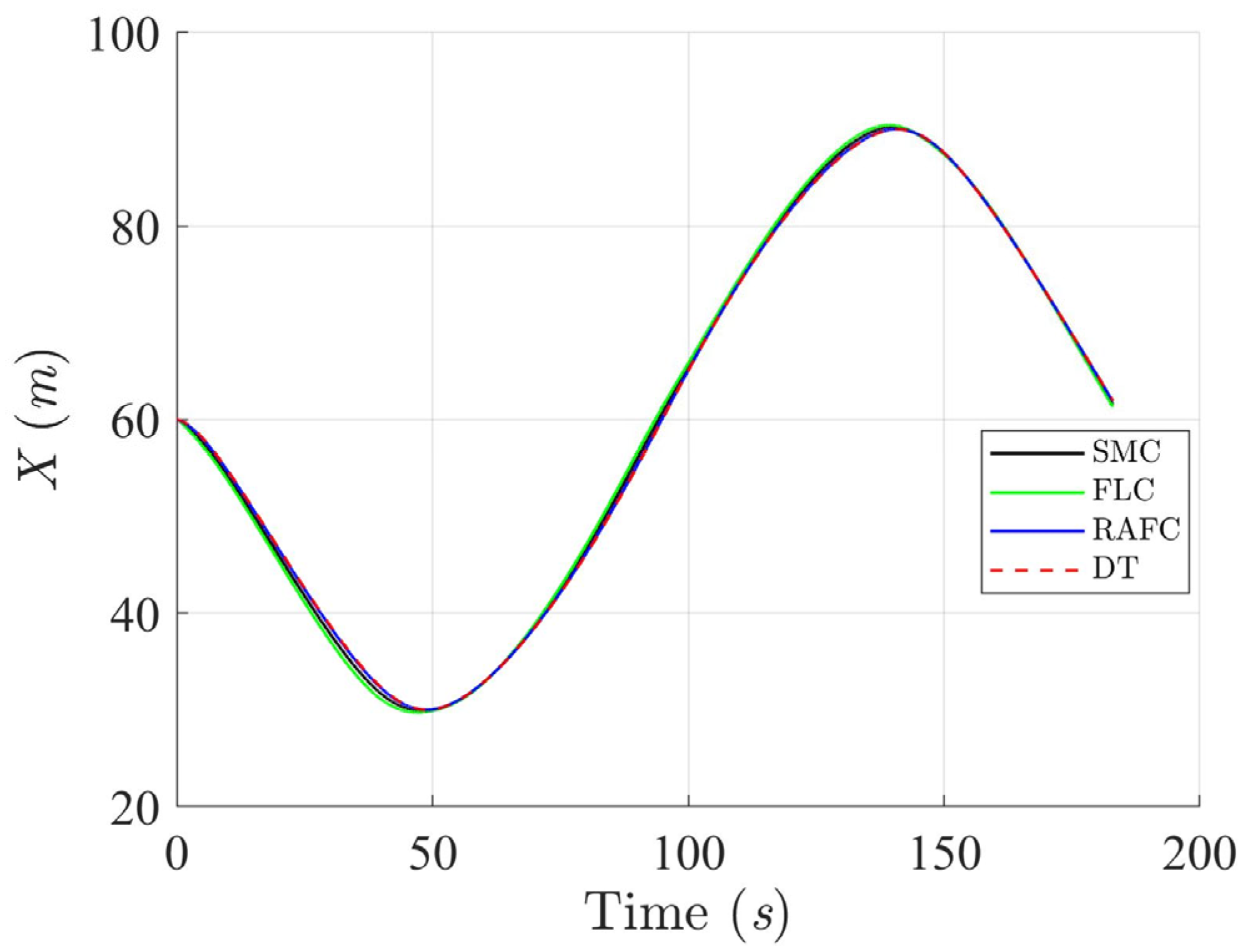
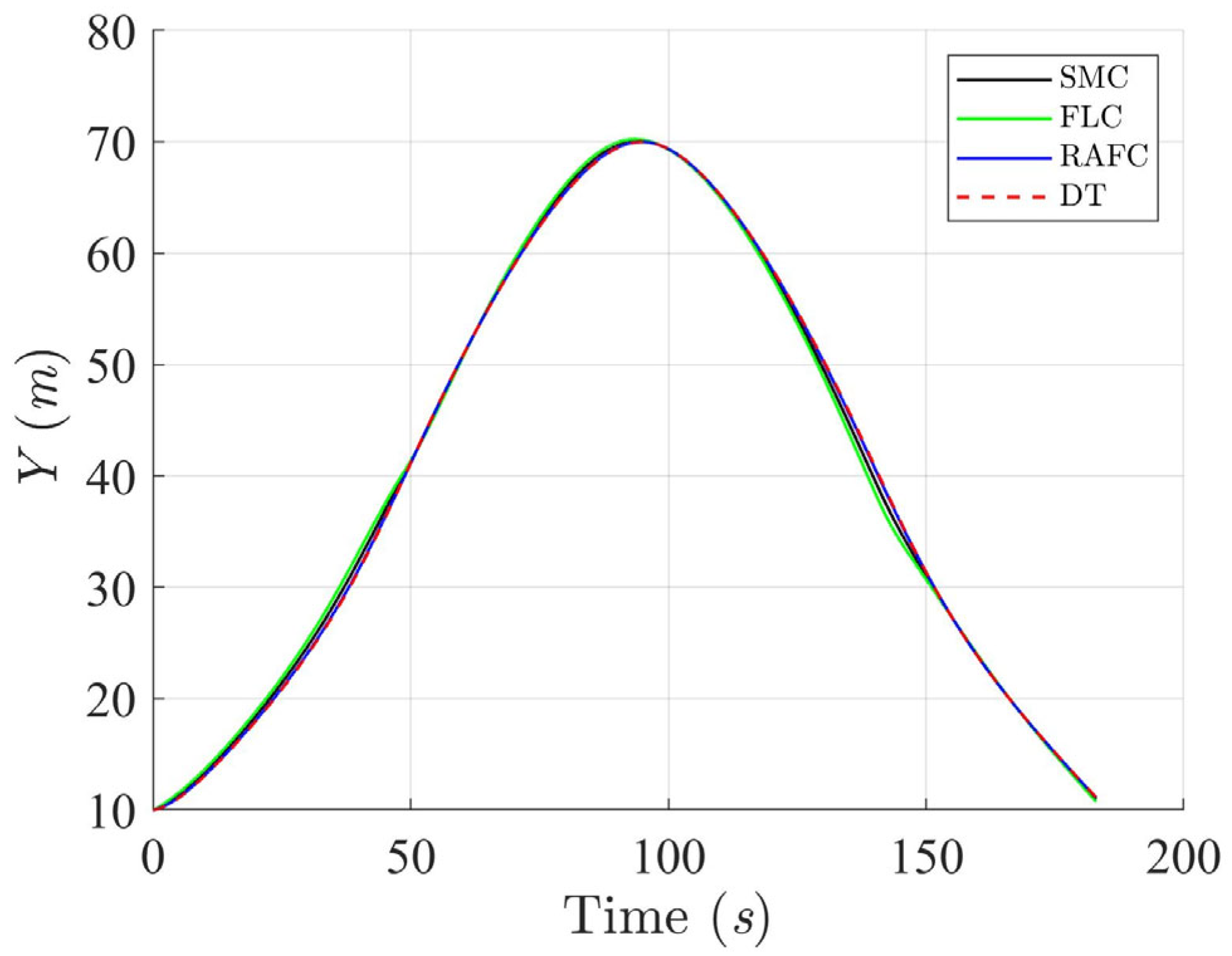
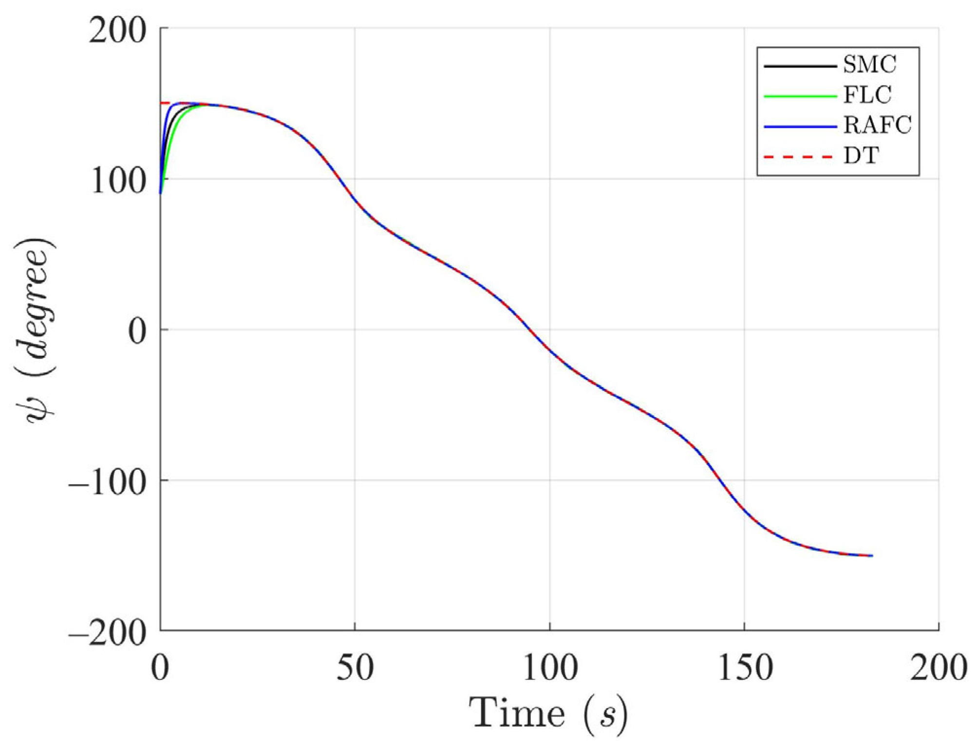
Figure 3,
Figure 4,
Figure 5 and
Figure 6 illustrate that the ASV can accurately follow the desired circular trajectory under the control of SMC, FLC, and RAFC. However, the RAFC consistently demonstrates better path conformity and heading stabilization. In particular, the RAFC yields smaller lateral and longitudinal deviations from the reference trajectory, and achieves faster convergence to the desired heading angle, even in the presence of significant ocean-environmental disturbances. These outcomes suggest that the RAFC is better suited for practical deployment where precise path-following under variable sea conditions is required.
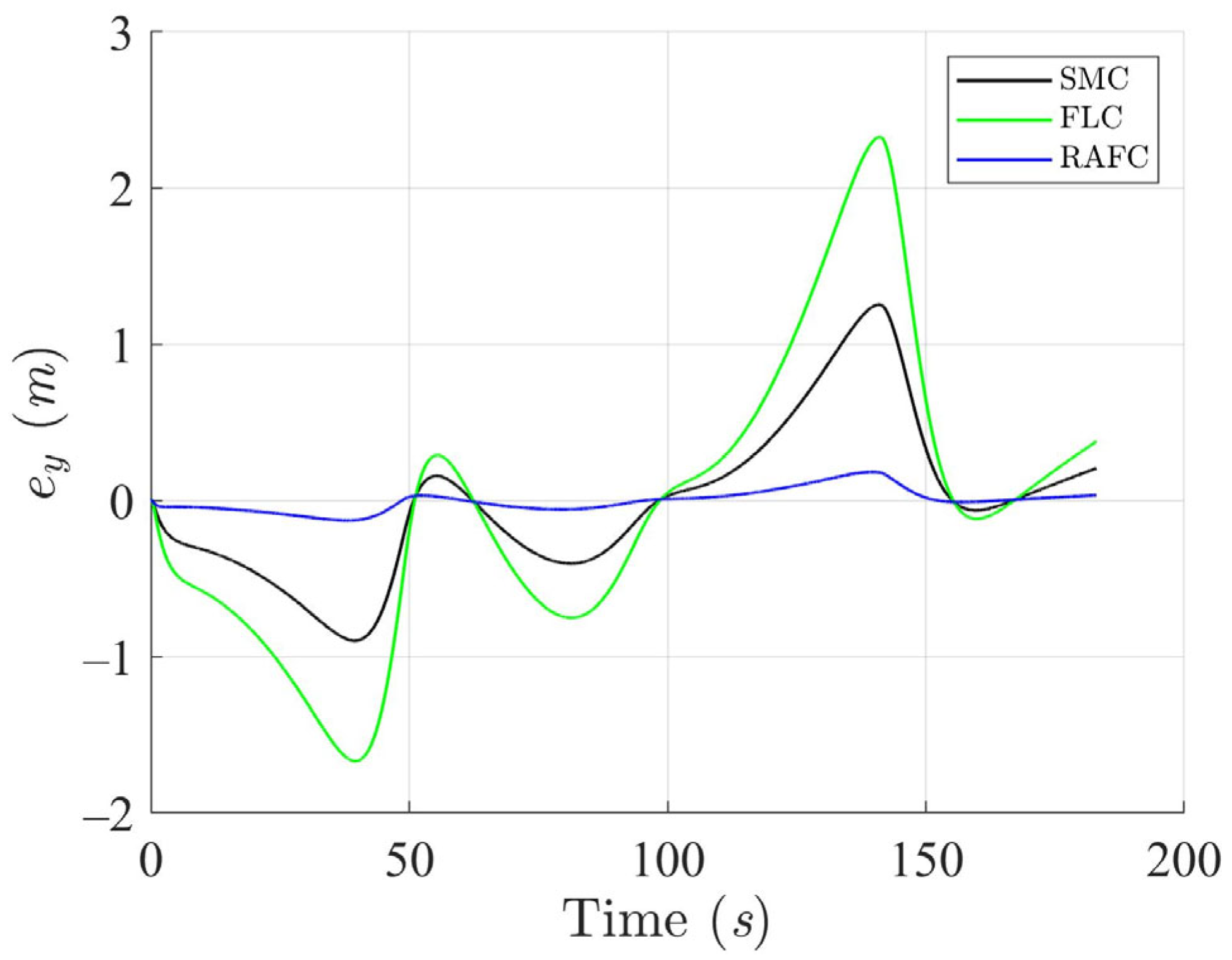
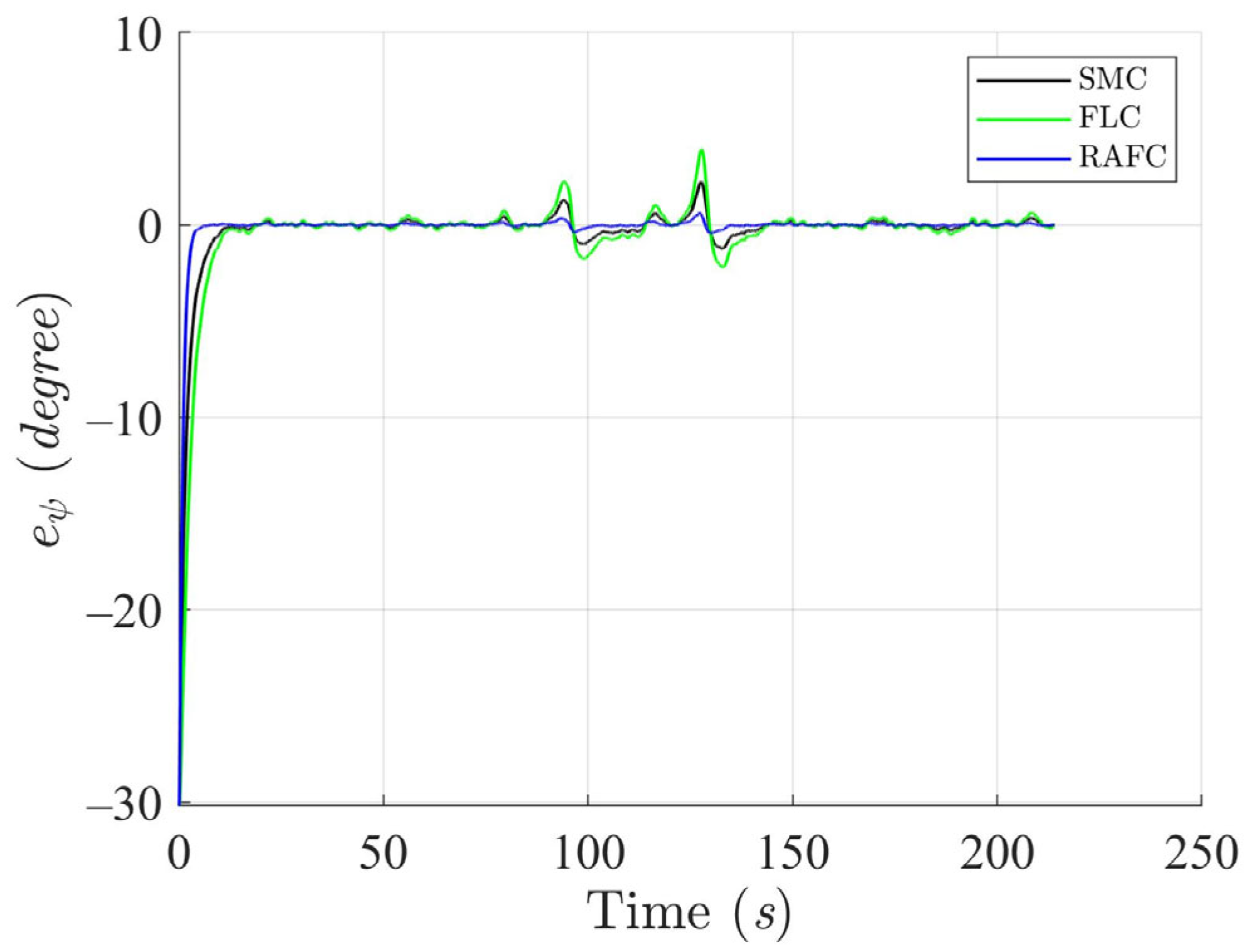
The tracking errors in the Cartesian plane and heading deviations are depicted in
Figure 7,
Figure 8 and
Figure 9. The SMC and FLC exhibit relatively high error magnitudes, reflecting their limited capability to adapt to sudden or nonlinear disturbance effects. In contrast, the RAFC maintains bounded and tightly regulated error profiles throughout the maneuver. This improvement is primarily attributed to the fuzzy inference system embedded in the RAFC, which dynamically compensates for unknown disturbances in real time without requiring precise models.
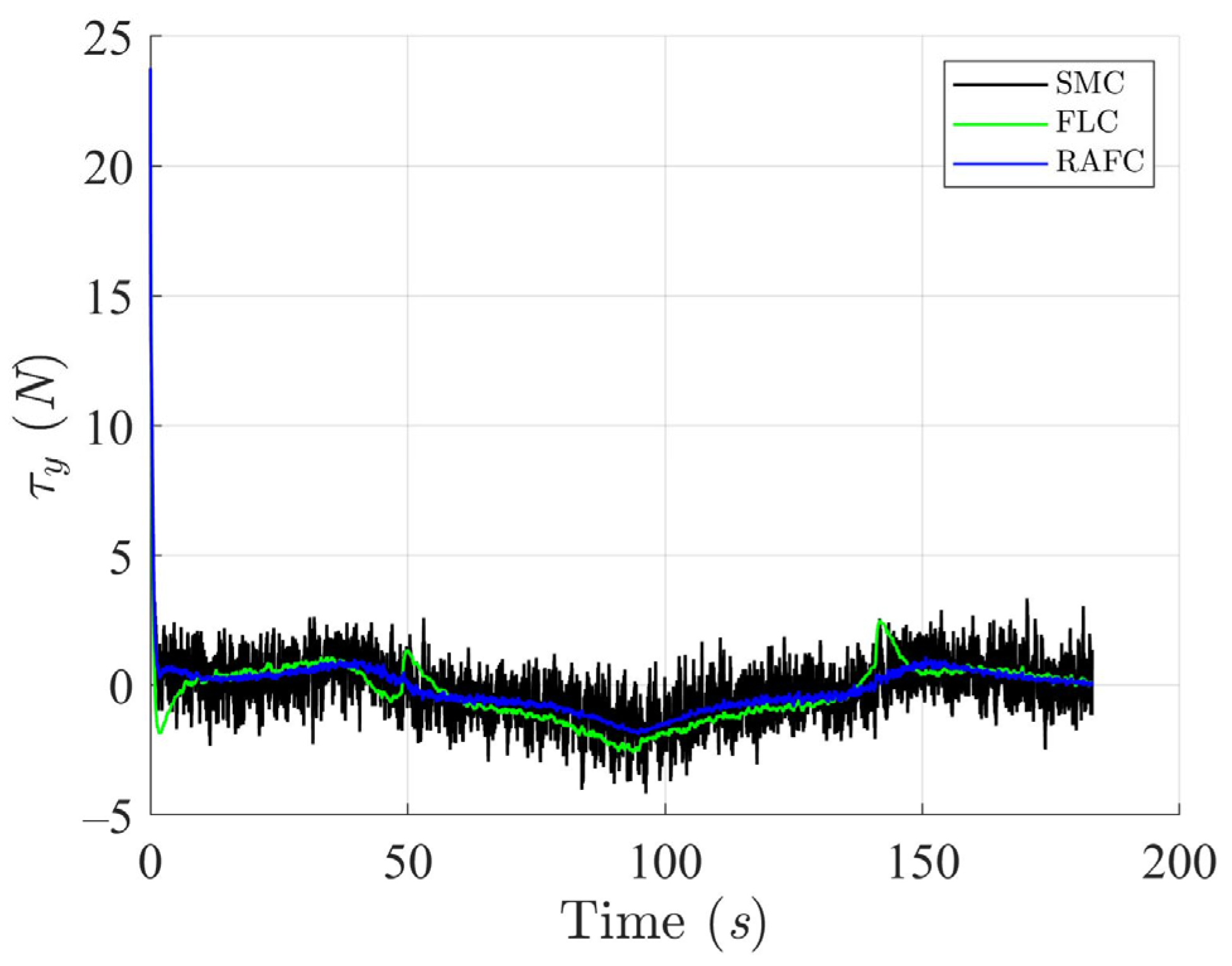
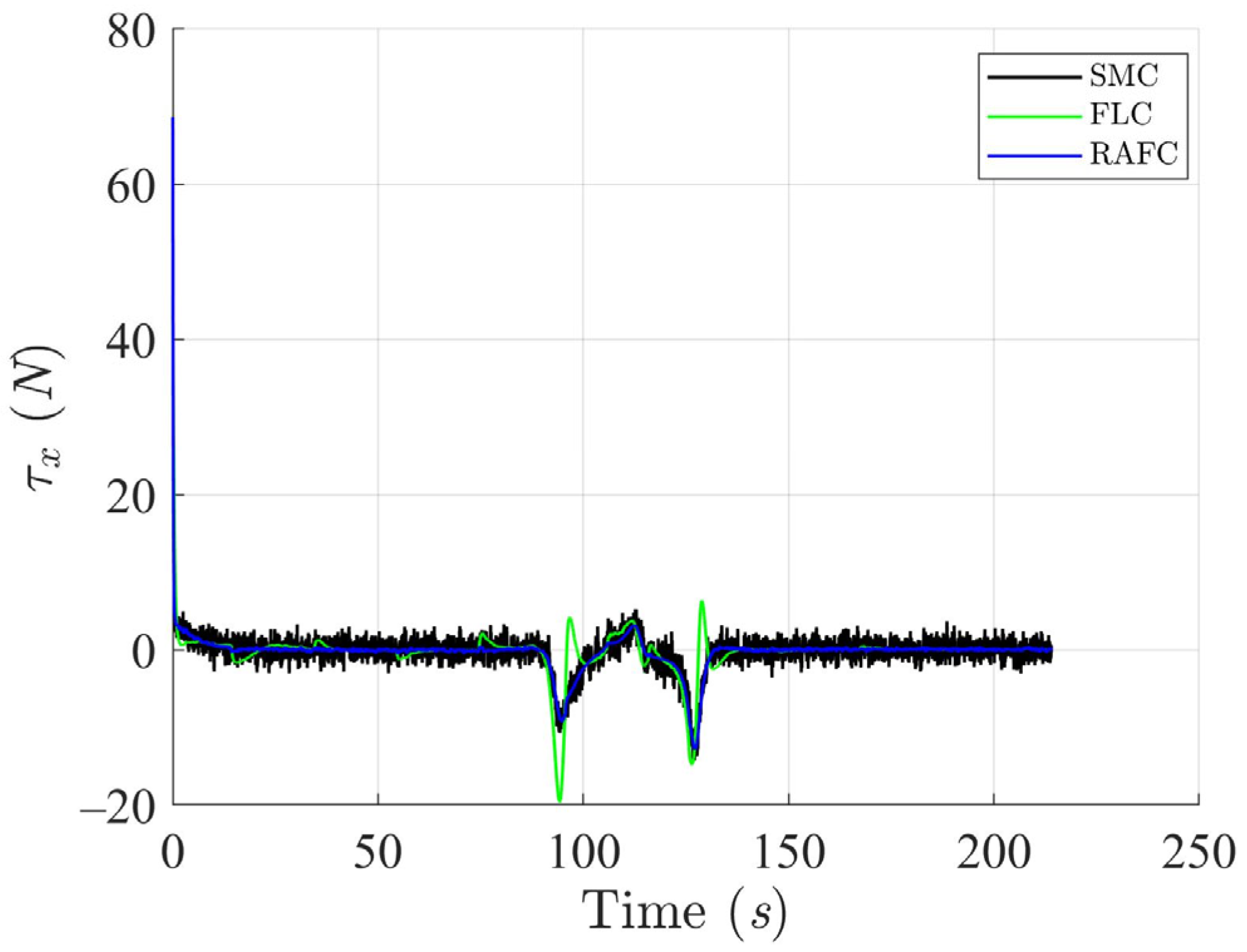
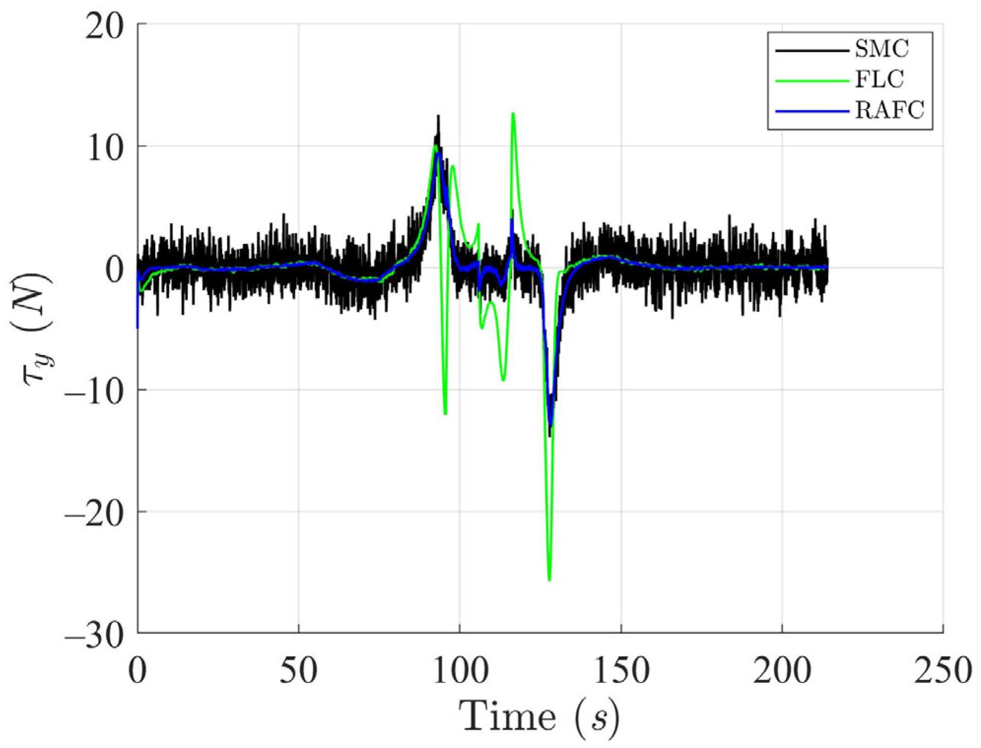
The applied control torques, as shown in
Figure 10,
Figure 11 and
Figure 12, highlight an important advantage of the RAFC framework: it achieves higher tracking accuracy with lower control effort compared to the SMC and FLC. This reduction in torque amplitude translates into decreased actuator workload and energy consumption—an essential consideration for long-endurance or autonomous surface vessels operating under power constraints.
Figure 13 presents the linear velocity profiles during the circular trajectory tracking. The SMC and FLC introduce high-frequency fluctuations and abrupt changes, especially during directional shifts, which may increase the risk of actuator wear or control saturation. The RAFC, on the other hand, produces a much smoother velocity curve with consistent acceleration and deceleration patterns, enhancing navigation safety and mechanical reliability. These improvements are critical for high-precision operations such as docking, survey missions, or obstacle avoidance.
Collectively, the simulation results under the circular trajectory scenario validate the practical utility of the proposed RAFC method. Compared to the SMC and the FLC, the RAFC
(1). Enhances trajectory and heading tracking accuracy;
(2). Minimizes tracking error and control chattering;
(3). Produces smoother and more stable velocity responses;
(4). Reduces control torque magnitude and energy expenditure.
These results confirm that the RAFC offers a robust, energy-efficient, and disturbance-resilient control solution for ASVs operating in highly dynamic and uncertain maritime environments.
4.3.2. Scenario 2 (Square Trajectory)
In the second simulation scenario, the ASV is commanded to follow a square trajectory composed of 14 predefined waypoints, as listed in
Table 5. The trajectory includes three straight-line segments and two sharp turns, creating a challenging condition that introduces abrupt directional changes. This test case is designed to evaluate and compare the trajectory tracking performance and disturbance rejection capability of the SMC, FLC, and the proposed RAFC under ocean-environmental disturbances. The initial conditions for the ASV in this scenario are presented in
Table 6.
To further evaluate the controller performance in non-smooth reference tracking scenarios, a square trajectory with sharp turning segments was adopted. This task reflects practical situations such as docking maneuvers or obstacle avoidance where abrupt directional changes are required.
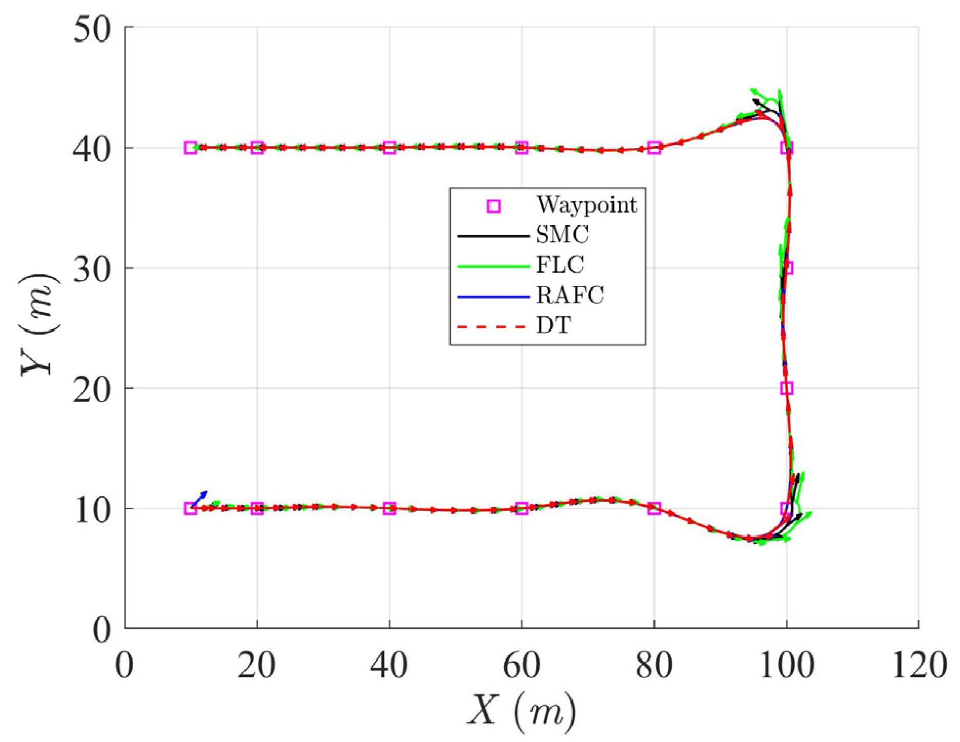
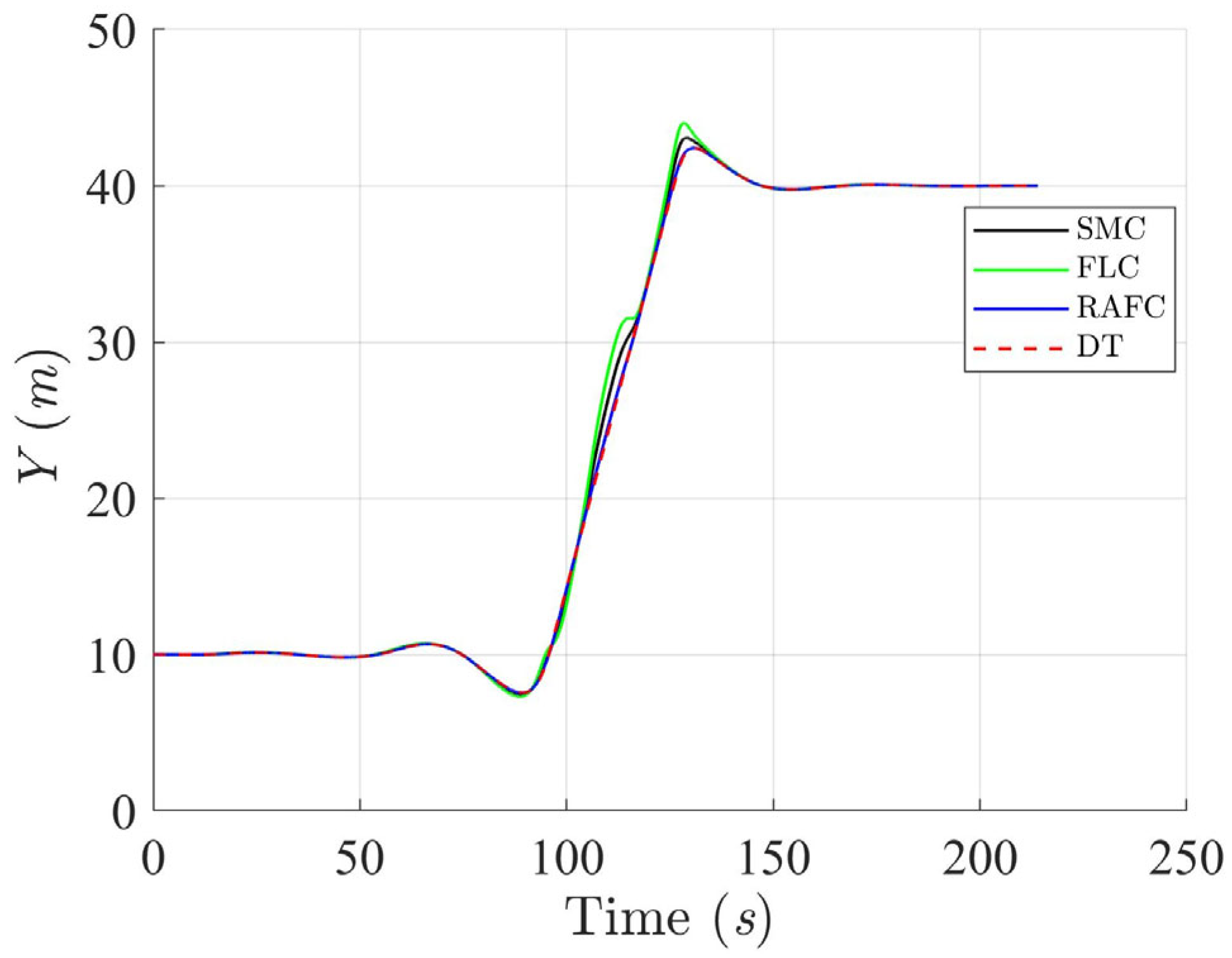
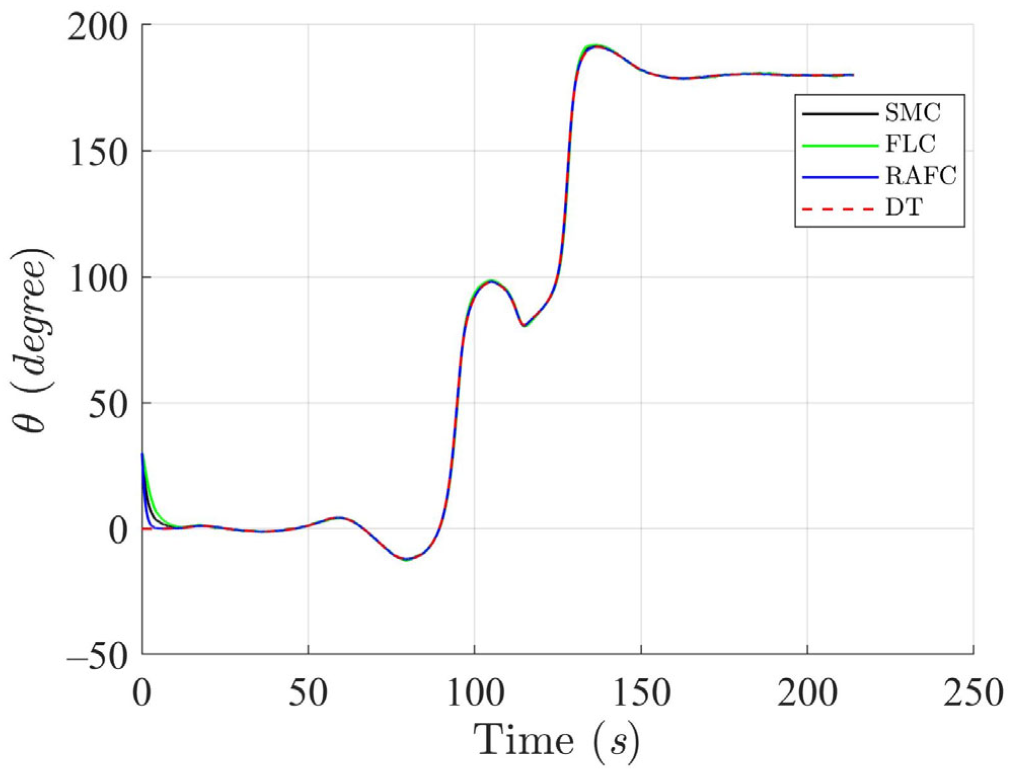
As shown in
Figure 14,
Figure 15,
Figure 16 and
Figure 17, the ASV controlled by the SMC and FLC exhibits significant trajectory deviation and heading instability, especially at trajectory corners where abrupt directional changes occur. The observed pose errors highlight the limited robustness of SMC and FLC during high-rate maneuvering. In contrast, the RAFC demonstrates accurate trajectory tracking with minimized overshoot and fast heading convergence. Notably, near turning points, the RAFC maintains close adherence to the reference trajectory, which is essential for real-time course corrections in constrained maritime environments.
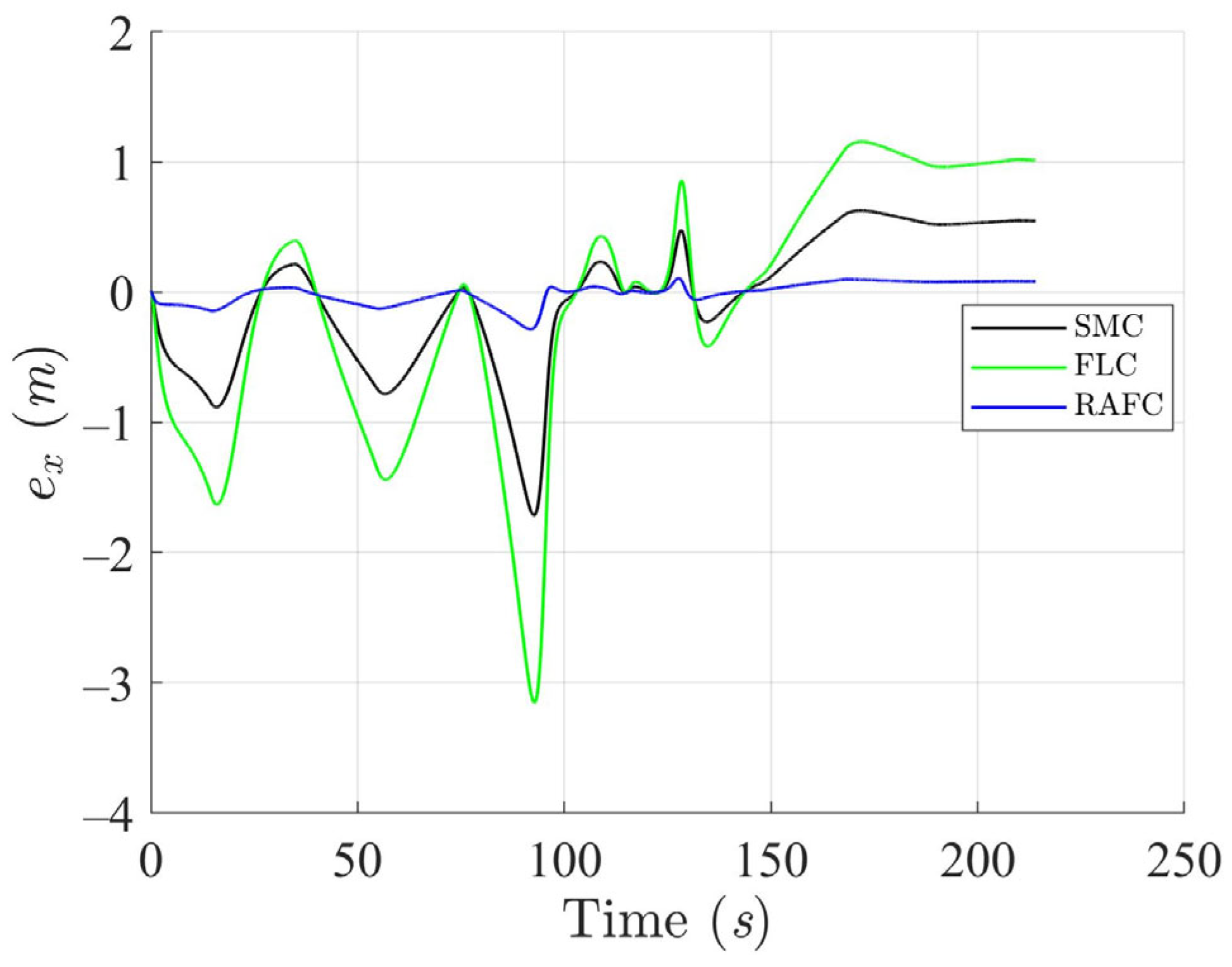
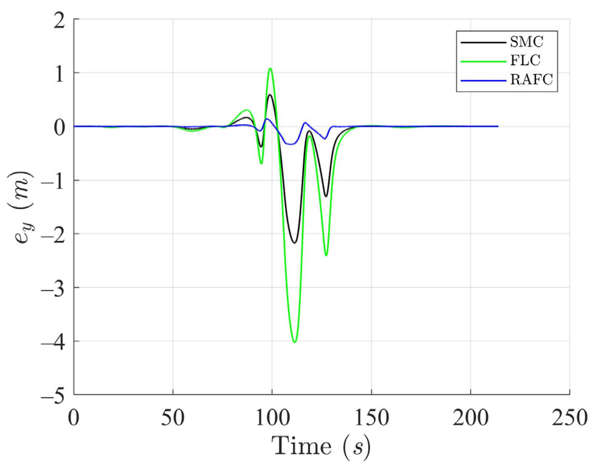
The effectiveness of both controllers in managing path and orientation deviations is further analyzed in
Figure 18,
Figure 19 and
Figure 20. The SMC and FLC show pronounced fluctuations in both position and heading error following direction changes, requiring longer durations to stabilize. Conversely, the RAFC maintains low error magnitudes and demonstrates a rapid return to steady-state behavior. These results highlight the RAFC’s superior disturbance-rejection capability and its effectiveness in stabilizing the ASV after abrupt trajectory changes, which is critical in applications involving reactive maneuvering.
The control torque responses generated by the three controllers are shown in
Figure 21,
Figure 22 and
Figure 23. While the SMC and FLC produce large control fluctuations, particularly at the turning points, the RAFC maintains smoother and lower-magnitude torque profiles. This efficiency implies a reduction in actuator effort, which not only lowers energy consumption but also minimizes mechanical stress on the propulsion system—an important factor for ensuring the reliability and longevity of ASVs operating in harsh marine environments.
Further insight into dynamic control smoothness is provided by
Figure 24, which displays the ASV’s linear velocity during the square trajectory task. The ASV controlled by SMC and FLC exhibits sudden spikes and discontinuities in speed, particularly at sharp corners. Such responses may compromise navigation safety and increase the risk of control saturation. In comparison, the RAFC maintains a continuous and gradual velocity profile, effectively mitigating abrupt transitions and suppressing chattering effects. This performance is indicative of a well-structured control law that accounts for real-world velocity constraints.
The results obtained from the square trajectory tracking simulation clearly demonstrate the practical benefits of the proposed RAFC design. Compared to the SMC and FLC, the RAFC
(1). Delivers more accurate path and heading tracking under sudden direction changes;
(2). Effectively suppresses tracking error overshoot and reduces recovery time;
(3). Produces smoother control actions and lower actuator workload;
(4). Maintains stable velocity transitions with minimal chattering.
These advantages establish the RAFC as a robust and energy-efficient control solution suitable for complex ASV missions that require frequent maneuvering, such as autonomous port operations, close-quarters navigation, or dynamic obstacle avoidance.
4.4. Monte Carlo-Based Robustness Evaluation Under Environmental Disturbances
To rigorously evaluate the robustness of the proposed RAFC strategy under uncertain maritime environments, Monte Carlo simulations were conducted for two trajectory tracking scenarios. In both cases, the ocean environmental disturbances—including wave excitation, wind loads, and current forces—were modeled as time-varying perturbations with randomly generated direction, amplitude, and phase. Four levels of disturbance magnitude were considered: 30%, 40%, 50%, and 60% of nominal values. For each level, 100 independent trials were executed to capture statistical performance variations. The RAFC method has practically shown high performance under a range of ocean perturbations, supported by Monte Carlo simulations.
4.4.1. Scenario 1 (Circular Trajectory)
Scenario 1 represents a circular trajectory characterized by smooth, continuous changes in heading and velocity. This scenario tests the controller’s capability to perform accurate tracking under gradually varying dynamic conditions.
Table 7 summarizes the results of the Monte Carlo simulations in terms of RMSE in position and heading in each degree of freedom.
The results indicate that the RAFC controller maintains high tracking precision with minimal deviation, even under strong disturbances. The RMSE values increase gradually with disturbance levels.
4.4.2. Scenario 2 (Square Trajectory)
Scenario 2 involves a square-shaped trajectory with sharp corners and abrupt transitions, which is more challenging due to the need for fast switching in heading and velocity. This scenario is representative of realistic operations such as maneuvering in constrained environments. The Monte Carlo simulation outcomes are reported in
Table 8.
As expected, scenario 2 exhibits slightly larger tracking errors and control efforts with respect to scenario 1 due to its discontinuous reference profile. Nevertheless, the RAFC controller continues to perform stably, maintaining bounded errors and smooth control signals throughout all trials.
The Monte Carlo results from both scenarios confirm the robustness and adaptability of the proposed RAFC. Under increasing disturbance levels, the tracking errors grow gradually rather than abruptly. The use of RMSE as the performance metric for trajectory errors provides a clear and interpretable evaluation framework. These findings validate the practical feasibility of the proposed method in dynamic and uncertain maritime environments.
