Article

Fatigue Analysis and Solid Particle Erosion Behavior of Nozzle Ring for Marine Turbocharger

1
Graduate School, Department of Marine Engineering, Mokpo National Maritime University, 91 Haeyangdaehak-ro, Mokpo 58628, Republic of Korea
2
Division of Cadet Training, Mokpo National Maritime University, Mokpo 58628, Republic of Korea
*
Author to whom correspondence should be addressed.
J. Mar. Sci. Eng. 2025, 13(7), 1230; https://doi.org/10.3390/jmse13071230
Submission received: 15 May 2025 / Revised: 9 June 2025 / Accepted: 10 June 2025 / Published: 26 June 2025

Abstract

This study investigates the degradation characteristics of turbocharger nozzle rings in marine diesel engines by conducting numerical analysis and solid particle erosion (SPE) tests to examine their structural stability and morphological surface damage trends. The fatigue analysis was conducted under a load condition corresponding to 100% output of the main engine, using ANSYS software. The SPE test was conducted in accordance with ASTM G76-05 standards, and the weight loss and erosion rate were calculated. Surface damage was closely examined through 3D analysis and scanning electron microscopy (SEM). The flow analysis revealed that the loads were highly concentrated at the nozzle ring inlet and the leading edge of the blades, with a maximum pressure coefficient of 0.07678 MPa. The load decreased toward the trailing edge of the nozzle ring, and the surface pressure coefficients of the flange, inner hoop, and outer hoop—where the nozzle ring blades are fixed—were found to be nearly identical. The fatigue life of the nozzle ring under 100% engine load was calculated as 1.377e+7 cycles, with a fatigue damage value of 1.32e+32. Notably, the fatigue life in the regions near the inner and outer hoops of the nozzle ring approached zero. The results of the SPE test using spherical SiO2 particles confirmed that the surface damage of the nozzle ring material, 316L stainless steel, followed a typical ductile material damage mechanism. In addition, the surface damage characteristics were significantly influenced by SPE test parameters such as the shape of solid particles, nozzle diameter, and impact angle.

1. Introduction

Diesel engines, employed as either main or auxiliary engines in ships, produce power through the combustion of fuel [1]. The turbocharger contributes to improved engine output by supplying scavenging air to the diesel engine, thereby increasing the mean effective pressure within the cylinder [2]. The turbocharger operates by using the exhaust gas of the main engine to rotate the turbine, and a compressor connected to the turbine compresses the air and delivers it to the combustion chamber [1]. Such a turbocharger is composed of several complex components, including the casing, rotor, blades, bearings, diffuser, and nozzle ring [3]. Damage to any of these components can adversely affect the function of the turbocharger, leading to insufficient supply of scavenging air to the main engine. As such, defects in the turbocharger system can directly affect the output of the main engine, potentially leading to adverse consequences such as delays in the vessel’s sailing schedule. Furthermore, depending on the situation, such failures may even cause serious secondary accidents, including grounding or collision [4,5].
Accordingly, numerous studies have been conducted in recent years to investigate the causes of turbocharger failures. Previous research has utilized fault tree analysis (FTA) to evaluate the reliability of the systems and predict potential failure causes [6]. Additionally, studies have examined the condition of turbocharger rotors and bearings through the analysis of vibration and acoustic signals [7]. Notably, based on the Sea-web Casualty and Events database, a study analyzed 42 cases of main engine turbocharger explosions reported between 1977 and 2022, employing both quantitative and qualitative approaches to identify correlations between turbocharger failures and engine characteristics such as manufacturer-specific rotational speed and output power [5]. In addition, there have been reported cases of accidents caused by the ingress of foreign objects into the turbocharger during vessel operation. Reported foreign objects that may lead to turbocharger damage include unburned oil, moisture, and other contaminants [8]. In the case of an 11.3 MW diesel engine for land-based power generation, a welding defect between the bellows’ metal base and the sliding plate allowed foreign material to enter, resulting in damage to turbocharger components such as the nozzle ring, blades, and shaft [9].
This study aims to investigate the degradation phenomena of the nozzle ring, one of the key components of the turbocharger, due to long-term operation from the perspectives of numerical analysis and material mechanics. The nozzle ring functions to convert the pressure energy of exhaust gas into kinetic energy, thereby driving the rotation of the turbine blades [10]. As the nozzle ring is directly exposed to high-temperature and high-pressure exhaust gases, thermal loads can become concentrated in specific regions, potentially leading to thermal deformation and fatigue damage of the material itself [11]. Therefore, various fatigue analysis studies have been conducted on the components of turbochargers to prevent internal damage and extend their service life. The combination of thermal transients and mechanical load cycles leads to thermo-mechanical fatigue damage of the material [12]. Accordingly, the thermal fatigue behavior of turbochargers—constantly exposed to high-temperature exhaust gases during engine operation—has also been analyzed to assess their durability [13]. Methods for determining fatigue life have been proposed through studies focused on fatigue reliability analysis and fatigue life prediction of turbocharger turbines [14]. Due to the severe mechanical and thermal cyclic loading experienced by the turbocharger housing of internal combustion engines during its service life or engine testing, a durability assessment model was proposed by integrating accelerated life test data analysis with the characteristics of intensive testing [15].
In addition, ash contained in the exhaust gas can collide with the turbocharger system, causing SPE. In particular, the nozzle ring is the first component to come into contact with the exhaust gas as it enters the turbocharger and is therefore constantly exposed to the SPE environment caused by ash particles. Erosion damage caused by the impact of solid particles contained in exhaust gas poses a serious problem in engineering applications involving fluid interaction. SPE is a major cause of component failure not only in marine exhaust gas systems such as turbochargers and economizer tubes [16], but also in steam and gas turbines of coal-fired power plants [17,18,19,20], as well as in boiler tubes [21,22,23]. Such failures are primarily caused by severe erosion due to unburned carbon and oxides contained in fly ash [24]. Fly ash typically comprises spherical particles ranging from 1 µm to 100 µm in diameter. The SiO2 content in cleaned ash is reported to be 78.66 wt.%, while that of ceramic microspheres is 53.55 wt.% [25]. As a result, substantial economic losses are inevitable during the maintenance and replacement of equipment components. Although stainless steel and nickel-based alloys are commonly used for such equipment components, their low resistance to SPE results in a relatively short service life [17,19,23]. In addition, SPE alters the surface roughness and geometry of the nozzle ring blades, thereby reducing the aerodynamic efficiency of the exhaust gas turbine [26,27,28]. In severe cases, SPE may cause localized stress concentrations, which can ultimately lead to blade failure and associated accidents [29,30]. Therefore, it is essential to clearly identify the damage characteristics of materials used in turbocharger systems and to explore viable alternatives through comprehensive research efforts. While existing studies have explored the general fatigue behavior of turbocharger components and the erosion mechanisms induced by solid particles, limited attention has been given to the combined effects of mechanical loading and erosive wear. In particular, there is a significant lack of research on the SPE behavior of turbocharger nozzle rings using spherical SiO2 particles under marine engine operating conditions. Therefore, this highlights the critical need for research aimed at understanding the combined damage mechanisms that can severely compromise the structural integrity of turbocharger nozzle rings.
This study aims to provide a comprehensive assessment of the degradation phenomena of turbocharger nozzle rings by employing both numerical simulations and experimental investigations. Initially, numerical simulations were performed to replicate real operating conditions, enabling analysis of the load distribution and fatigue behavior of the nozzle ring. Following this, SPE tests employing spherical SiO2 particles were conducted to evaluate the effect of fly ash present in exhaust gases on the nozzle ring’s surface damage and erosion characteristics. By considering both fatigue and erosion aspects, this study ultimately aims to provide deeper insight into the damage mechanisms of turbocharger nozzle rings and contribute to the development of improved design and maintenance strategies for marine engine systems.

2. Experimental Method

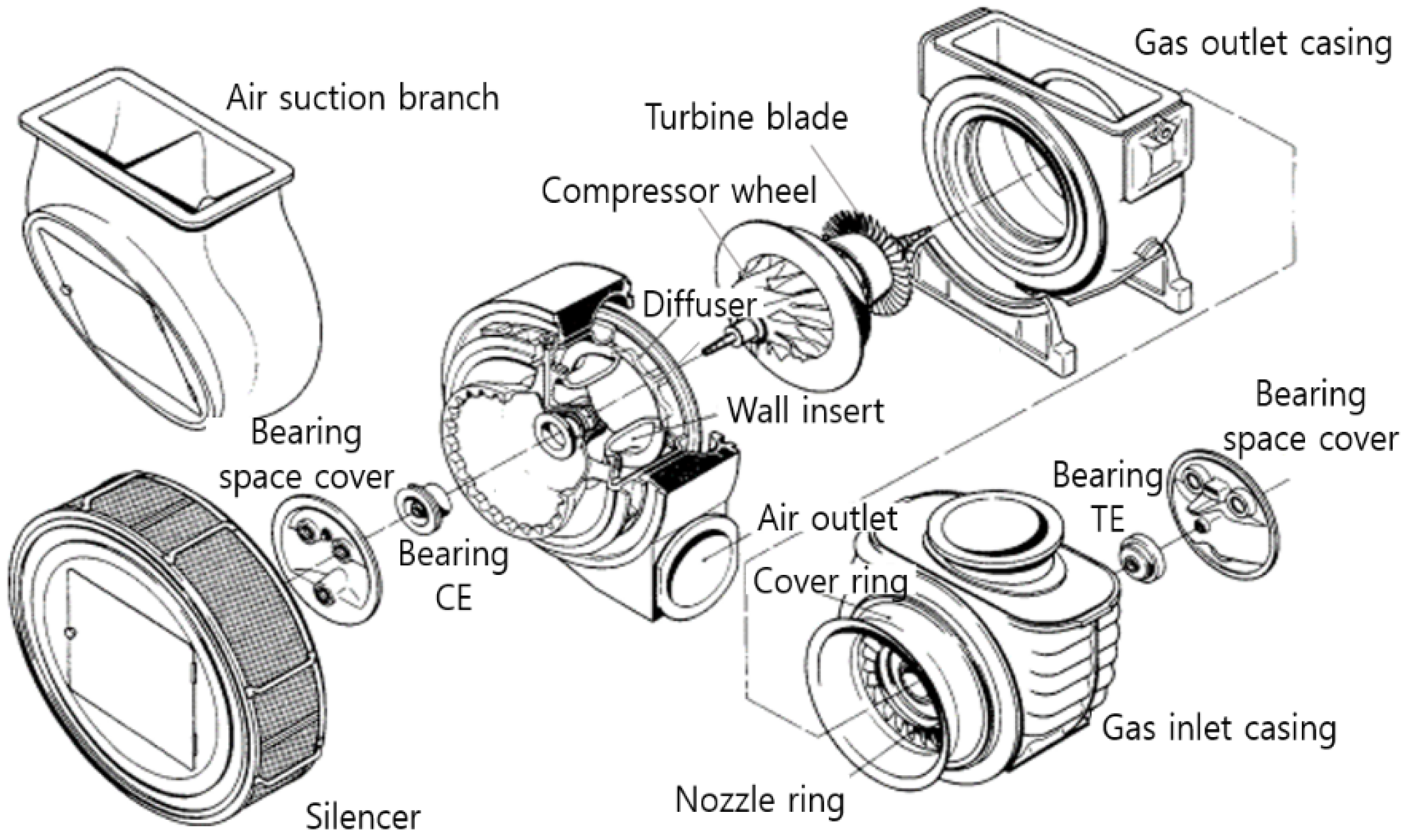
2.1. Turbocharger Description

The main engine applied in this study is the 6S35MC Mk7 model manufactured by HYUNDAI B&W (Ulsan, Republic of Korea), featuring six cylinders and a maximum continuous rating (MCR) of 6060 bhp at 173 rpm. Each cylinder has a bore of 350 mm and a stroke of 1400 mm. The main engine is equipped with one VTR454 model turbocharger from ABB (Baden, Switzerland), which has high reliability in terms of efficiency and maintenance of large diesel engines. The turbocharger is designed for a maximum rotational speed of 17,520 rpm and can withstand exhaust gas temperatures up to 590 °C. Figure 1 illustrates the schematic structure of the turbocharger. To maximize the efficiency of exhaust gas discharge and scavenging air supply, the turbocharger’s turbine wheel and impeller are equipped with a nozzle ring and diffuser. The nozzle ring acts as a guide vane to convert pressure energy into velocity energy, and the diffuser is used to convert high-velocity compressed air passing through the impeller into pressure energy. The technical specifications and structural information provided above are based on internal documentation, including the “Final Drawings for Main Engine” and the “Instruction and Operating Manual for Fitting and Accessories”, officially supplied by the engine and turbocharger manufacturers.

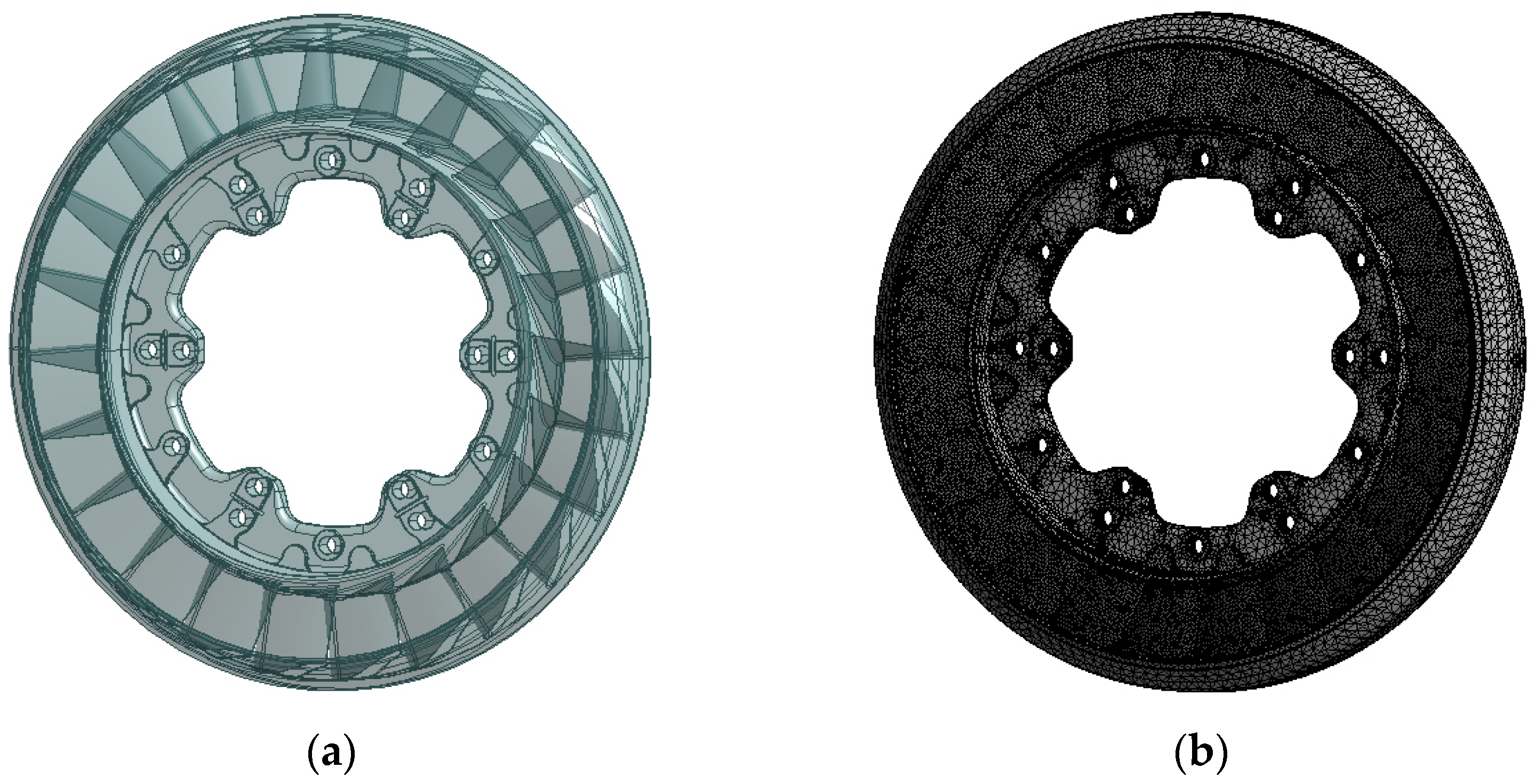
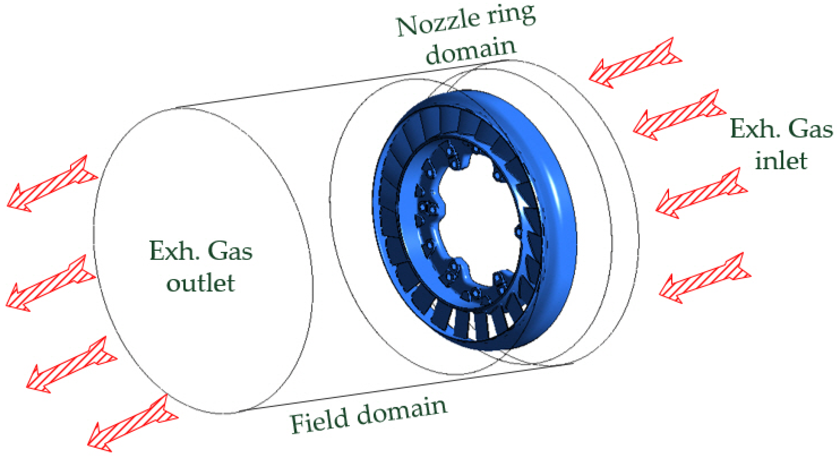
2.2. Numerical Analysis

The 3-dimensional model of the nozzle ring used for numerical analysis in this study is shown in Figure 2a, while Figure 2b presents the mesh of the finite element model. Flow analysis of the nozzle ring was conducted using the commercial software ANSYS (Version 2023). The pressure coefficient on the turbine blade surface, obtained from structural analysis, and the exhaust gas temperature at the turbocharger inlet were applied as loading conditions. The fatigue analysis was based on the equivalent stress values of the nozzle ring. Since the scavenging air pressure and exhaust gas temperature of the main engine remain constant with respect to RPM, they were applied as cyclic loading conditions. The flow field of the analysis model comprised more than 8 million nodes, utilizing a hybrid mesh of hexahedral and tetrahedral elements. As illustrated in Figure 3, the inlet boundary of the nozzle ring flow domain was subjected to a uniform pressure condition, whereas the outlet was defined with an averaged static pressure condition. The shear stress transport (SST) turbulence model enables accurate resolution of complex boundary layer behavior along wall surfaces; it offers stable and reliable predictions in free-stream flow regions. In particular, its ability to resolve boundary layer separation and reattachment makes it well-suited for predicting surface pressure coefficients on complex nozzle ring blade geometries [31,32]. The mechanical properties required for the numerical analysis of the nozzle ring applied in this study are presented in Table 1.

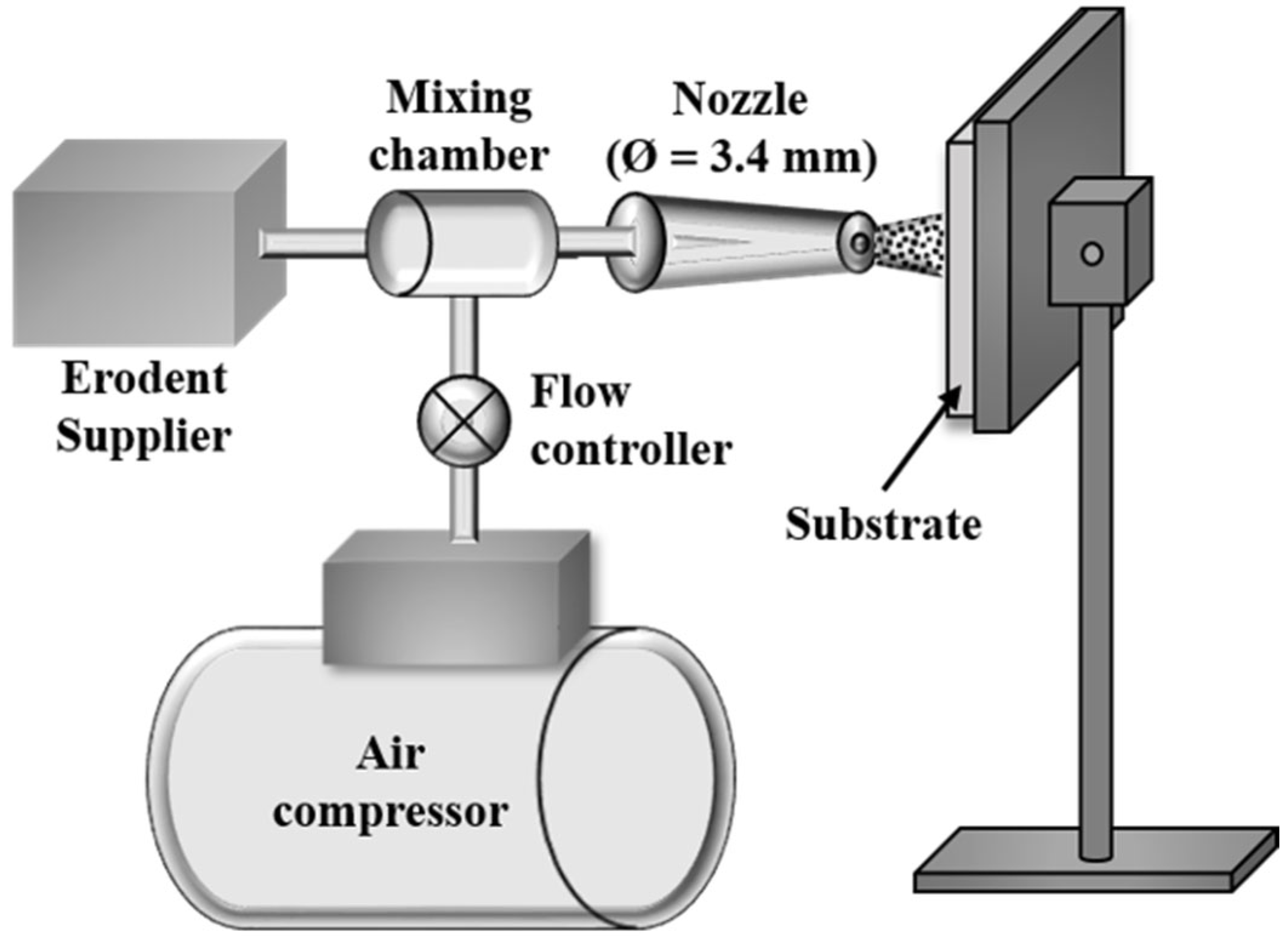
2.3. Solid Particle Erosion Test

The specimens were fabricated using 316L stainless steel, the material of the nozzle ring, and their chemical composition is presented in Table 2. Each specimen was precisely machined to dimensions of 20 mm × 20 mm × 5 mm and polished progressively with sandpaper up to #600 grit. After ultrasonic cleaning in distilled water, the specimens were dried by a drier using hot air. The SPE test was performed in accordance with ASTM G76-05 [33]. An overview of the SPE test setup is illustrated in Figure 4, and the specific test parameters are provided in Table 3. For the SPE test, commercially available spherical SiO2 particles were used as the erodent, selected due to their close resemblance in composition and morphology to the primary constituents of fly ash, and the SEM image of these particles is shown in Figure 5. The SPE test was conducted in triplicate for each test condition. Following the tests, the specimens were ultrasonically cleaned in distilled water, dried with hot air, and stored in a desiccator to prevent moisture absorption. The mass of each specimen was measured before and after testing using an electronic balance (ME204T, Mettler Toledo, Columbus, OH, USA) with a resolution of 10−4 g, enabling the calculation of average weight loss and erosion rate. The damaged surface was analyzed for the width and depth of the eroded area using a confocal 3D laser microscope (OLS5000, Olympus, Jiangsu Caidao Precision Instruments Co., Ltd., Kunshan, China) after the SPE tests. Furthermore, detailed observations of the surface morphology were performed using SEM (SNE-4500M, SEC, Daejeon, Republic of Korea). The chemical composition of the fly ash collected from the exhaust gas system of the main engine was analyzed using an energy dispersive X-ray spectrometer (EDS) integrated with a scanning electron microscope (SEM). To identify the mineralogical crystal structure, X-ray diffraction (XRD) analysis was performed using a SmartLab system (Rigaku Corporation, Tokyo, Japan).

3. Results and Discussion

3.1. Load Distribution

As the load acting on the nozzle ring varies with engine operating conditions, numerical analysis was performed using the data obtained from the shop test, as illustrated in Figure 6. To evaluate the structural characteristics of the nozzle ring, surface loads were applied locally to specific regions. The fatigue analysis in this study was carried out under a loading condition corresponding to 100% engine output at 173 rpm. As shown in Figure 7, the pressure coefficients obtained from the flow analysis were applied as surface loading conditions on the nozzle ring. The pressure coefficients were distinguished between the inlet and outlet regions, with the maximum values clearly indicated. The pressure coefficient was found to be high near the nozzle inlet and the leading edge of the blades, with a maximum pressure of 0.07678 MPa. Due to the airfoil shape of the nozzle ring blades, the pressure coefficient tends to decrease toward the trailing edge. The surface pressure coefficients of the flange where the nozzle ring blade is fixed and inner/outer hoop indicate almost similar values. In addition, to evaluate the mesh dependency of the numerical analysis model, the nozzle ring blade was modeled using various mesh sizes. Static structural analyses were performed on a total of seven models, including the one with the initially set 3 mm mesh size. The results for the different mesh models are presented in Figure 8, with blade deformation and strain of the nozzle ring used as indices for assessing mesh dependency. The static analysis results became consistent for models with more than 900,000 mesh elements. Therefore, this study was conducted using the 900,000-mesh model as the basis.

3.2. Fatigue Analysis

The nozzle ring analyzed in this study is subjected to extreme conditions involving repeated loading and high temperatures, which may lead to a reduction in material strength. Therefore, it is essential to predict sufficient structural integrity to ensure stable operation. Accordingly, static structural analysis was conducted to assess the structural characteristics of the nozzle ring, using blade deformation and maximum equivalent stress as evaluation metrics. Figure 9 illustrates the results for the pressure surface of the nozzle ring blade, which is most affected under the 100% engine load condition. As shown in Figure 9a, the cross-section was segmented along the chord line of the leading edge to investigate the localized characteristics of the pressure surface. As shown in Figure 9b, the maximum blade deformation was 0.41 mm at the midsection, where c/C = 1.0. The maximum equivalent stress, illustrated in Figure 9c, exceeded 8000 MPa and showed a high concentration near the edge of the blade fraction at c/C = 1.0. While blade deformation was concentrated in the central region of the blade fraction, the equivalent stress exhibited a contrasting distribution, with higher values observed near the edges. This high concentration of equivalent stress indicates a strong likelihood of bending deformation and potential failure near the trailing edge. The results of the fatigue analysis were evaluated in terms of fatigue life and fatigue damage, and their distributions are shown in Figure 10. Fatigue life and fatigue damage were calculated based on a reference value of 10 e + 32 . At a main engine speed of 173 rpm, the fatigue life was 1.377 e + 7 cycles, and the fatigue damage was 1.32 e + 32 . The fatigue life of the blade was found to be nearly zero in the region where it interfaces with the hoop, which is presumed to result from internal stresses caused by cyclic loading. In contrast to the deformation pattern, the trailing edge of the blade demonstrated a relatively high fatigue life. As shown in Figure 10b, the fatigue damage of the nozzle ring was inversely proportional to the fatigue life, with higher values concentrated near the blade edges, while both the leading and trailing edges displayed generally lower damage levels. Figure 11 presents the variation in fatigue life and fatigue damage with respect to the main engine speed. An inverse relationship was observed between fatigue life and fatigue damage, with a notable inflection occurring near 164 rpm.

3.3. Solid Particle Erosion Characteristics

Figure 12 presents the 3D analysis images and surface profile analysis results obtained after the SPE test. As shown in the 3D images in Figure 12a–c, circular erosion damage on the surface progressively increased in size and depth with the SPE test time. The geometry of the eroded area is clearly illustrated in the surface profile shown in Figure 12d. Furthermore, Figure 13 presents the measured width and depth of the eroded area with the SPE test time, as obtained through surface profile analysis. The depth of erosion damage continued to increase with the progression of the SPE test. In contrast, the width of the eroded area showed a relatively steep increase up to 30 min, followed by a more gradual rise, stabilizing within the range of approximately 4.8 to 5.3 mm. This trend was also observed in Figure 14, which presents the weight loss and erosion rate following the SPE test. The weight loss showed a continuous increase as the SPE test duration progressed. However, the erosion rate showed a rapid increase up to 30 min of SPE testing, after which it exhibited a more gradual rise, stabilizing within the range of approximately 3.3 to 3.9 mg/h. The increase in weight loss with the progression of the SPE test indicates the continuous accumulation of material loss due to ongoing erosion. The sharp rise in erosion rate up to 30 min of SPE testing, followed by a more gradual trend thereafter, can be attributed to the nature of the erosion progression observed in Figure 13. Within the first 30 min, the eroded area increased substantially in both width and depth, resulting in a steep rise in material loss. After that point, this trend can be explained by the fact that erosion damage progressed primarily in the depth direction, with minimal expansion in width, resulting in a reduced erosion rate of material loss. The overall erosion damage pattern observed in this study is attributed to the influence of test parameters, such as the diameter of the erodent-discharging nozzle and the distance between the nozzle and the specimen, which constrained erosion in the width direction. In contrast, the 90° impingement angle consistently induced erosion progression in the depth direction. In addition, previous studies have concluded that surface erosion caused by SPE is influenced by various factors, including particle shape, size, velocity, and material properties [34,35]. In particular, it has been confirmed that for solid particles, the most influential parameters affecting SPE are the particle properties and the impact conditions [36]. Particle properties refer to the type of solid particles, material, size, and shape, while impact conditions take into account the particle velocity and angle of impingement.
Figure 15 presents the SEM micrograph and corresponding EDS analysis of fly ash samples collected from the exhaust system of the main engine. The particles were primarily in the size range of 1 to 5 µm, with most of them exhibiting nearly spherical morphology. The chemical composition of the fly ash primarily consists of O, Al, Si, K, and Na, In particular, O, Al, and Si were predominantly concentrated in the spherical particles, indicating that they are the main constituents of the fly ash. These results are consistent with the XRD analysis presented in Figure 16, which was conducted to identify the crystal structure of the fly ash. Strong diffraction peaks of quartz (SiO2) were observed at 2-theta values of 21° and 27°, while peaks corresponding to mullite (Al6Si2O13) were primarily detected at 17° and 26°. Therefore, the spherical particles observed in Figure 15 are presumed to be the mineral phases mullite and quartz. Such spherical particle morphology significantly influences the SPE mechanism. Figure 17 shows the surface morphology of the eroded area after the SPE test, captured using SEM. Figure 17a, representing the initial stage of the SPE test, shows a surface that appears slightly compressed due to repeated micro-forging effects from the spherical solid particles depicted in Figure 5. Consequently, the overall surface exhibits a gentle wave-like pattern. Extruded lips were also observed around some of the indented surface regions. Such surface features are typically observed in ductile materials [37]. Figure 17b shows the surface morphology at the end of the SPE test, where extruded lips were significantly developed over the entire surface, appearing as a rough wave-like pattern. The significant development of extruded lips is believed to result from the continued progression of erosion in the depth direction over time during the SPE test, as shown in Figure 12d. As erosion deepened, solid particles increasingly impacted the inclined surfaces of the damaged area, thereby reducing the impact angle, which is considered to be the main cause of this phenomenon. The repeated impacts of solid particles not only generate multiple extruded lips on the surface but also promote material removal through fragmentation. Therefore, as shown in Figure 14, the weight loss is considered to exhibit a continuously increasing trend with the progression of the SPE test. A similar pattern of surface damage has been reported in previous studies by other researchers. Jung and Kim conducted an SPE test on 9Cr-1MoVNb steel using spherical ZrO2–SiO2 composite ceramic balls and observed wave-like surface damage similar to that found in the present study [38]. Meanwhile, Chen and Li applied a micro-scale dynamic model to simulate SPE for triangular, square, and circular particle shapes [39]. The simulation results showed that triangular particles produced the highest erosion rate, followed by circular and square-shaped particles. Levy and Chik examined the influence of particle shape on erosion behavior through SPE tests conducted on AISI 1020 steel, utilizing both spherical and angular steel particles [40]. As a result, the erosion rate caused by angular particles was found to be four times higher than that of spherical particles. This was attributed to the fact that angular particles were reported to concentrate kinetic energy more efficiently. As erosion rates are highly dependent on the shape of erodent particles, the appropriate selection of erodents that closely resemble actual environmental conditions is of great importance.

4. Conclusions

This study investigated the degradation behavior of the turbocharger nozzle ring in a marine diesel engine through fatigue analysis and material mechanics-based experiments. The following conclusions were drawn:
(1)
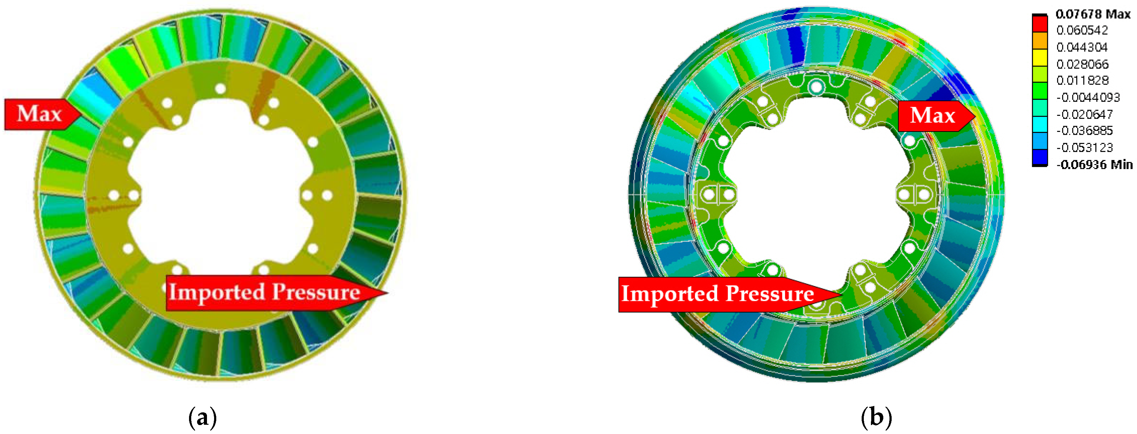
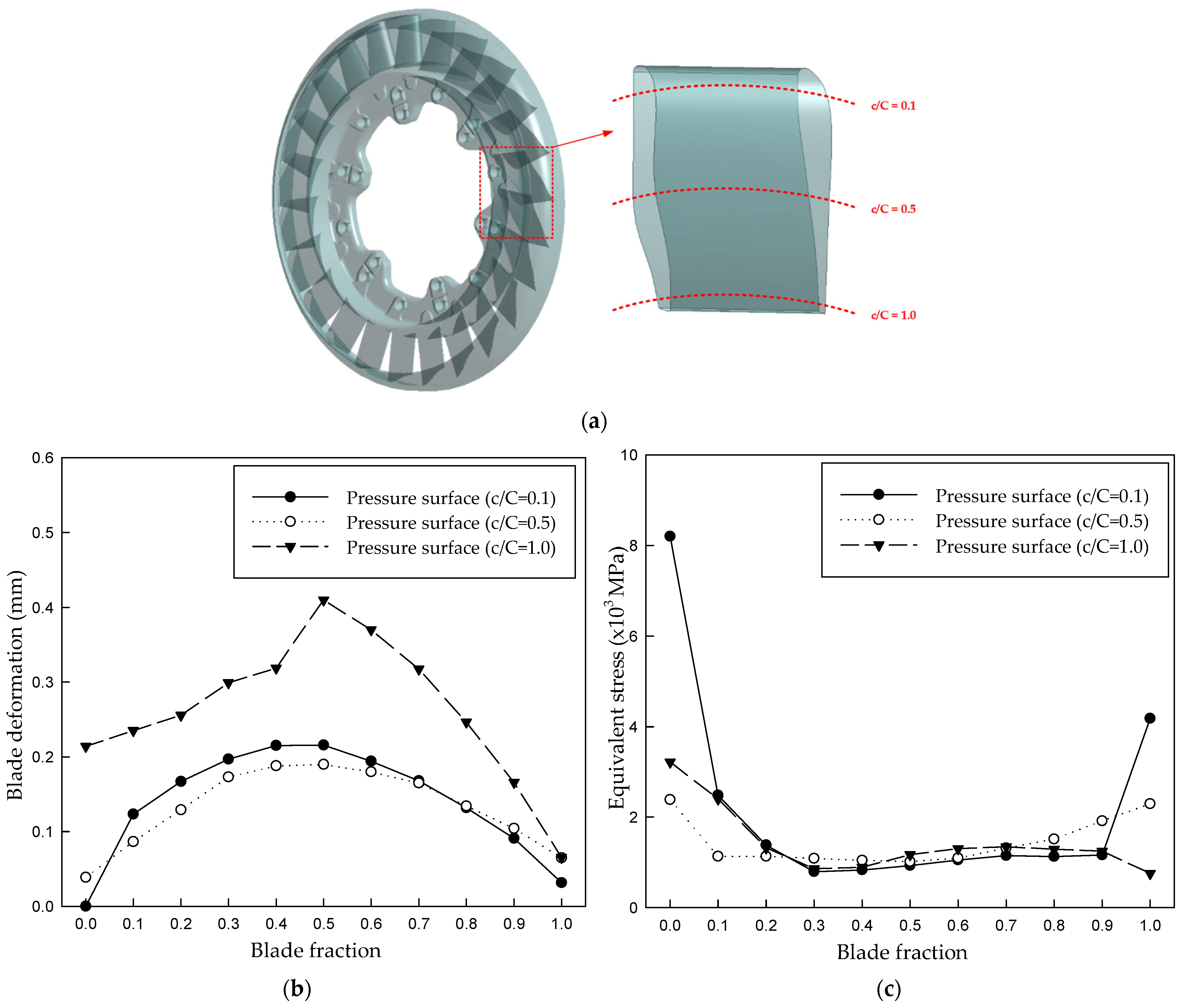
Static structural analysis was performed using the surface pressure coefficients obtained from flow analysis as boundary conditions, and contrasting distributions of blade deformation and equivalent stress were observed.
(2)
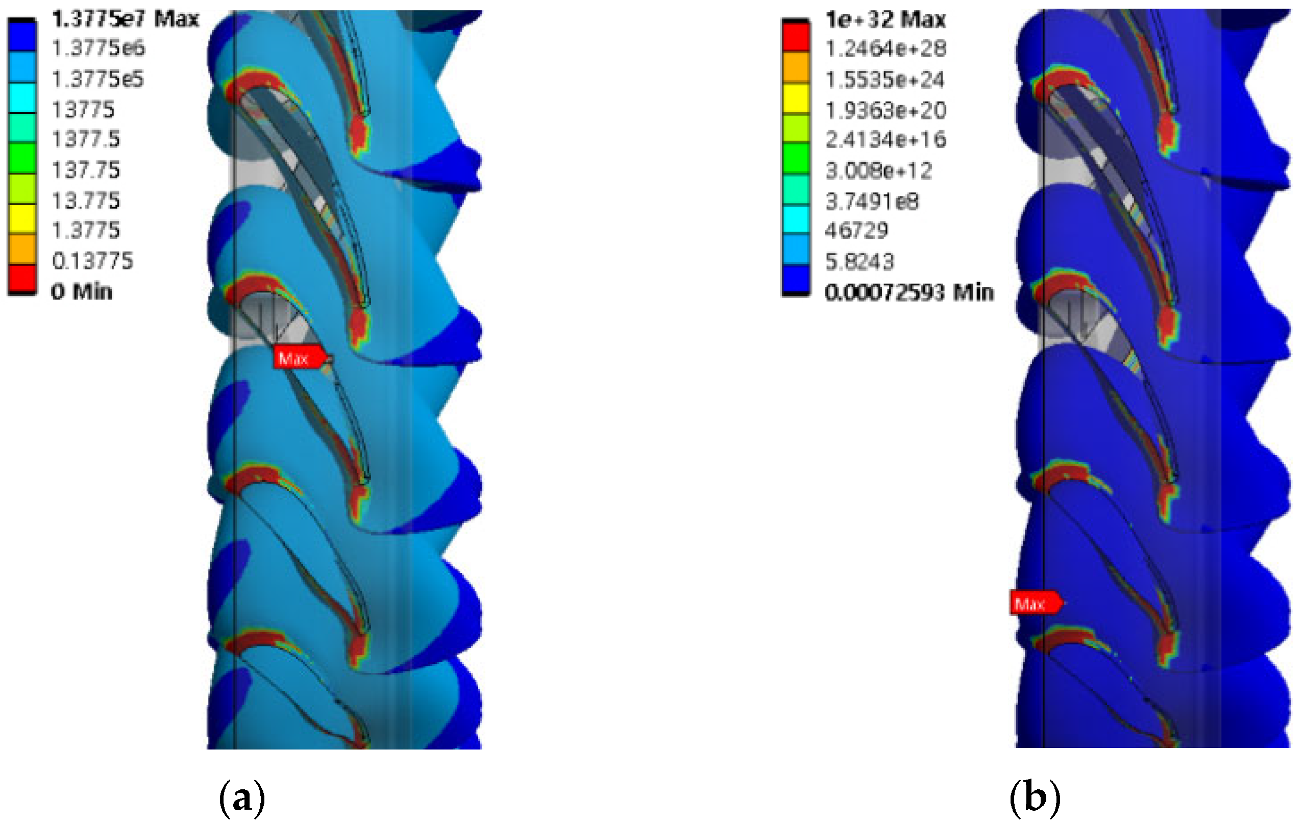
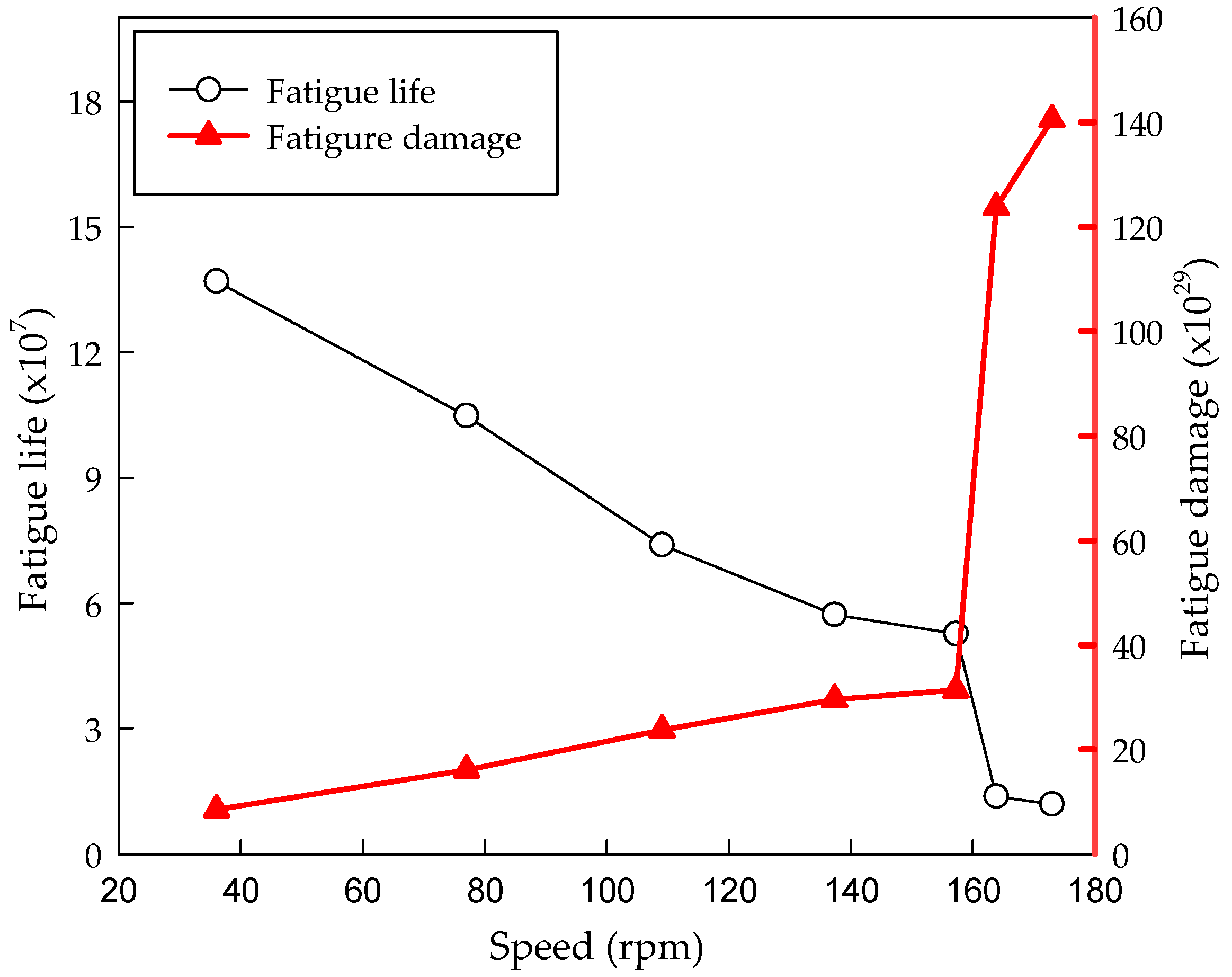
A stress-based fatigue analysis was conducted, revealing that the fatigue life of the blade was extremely low in the region where the blade interfaces with the hoop. In contrast, fatigue damage showed an inverse relationship with fatigue life, with higher values concentrated near the blade edges.
(3)
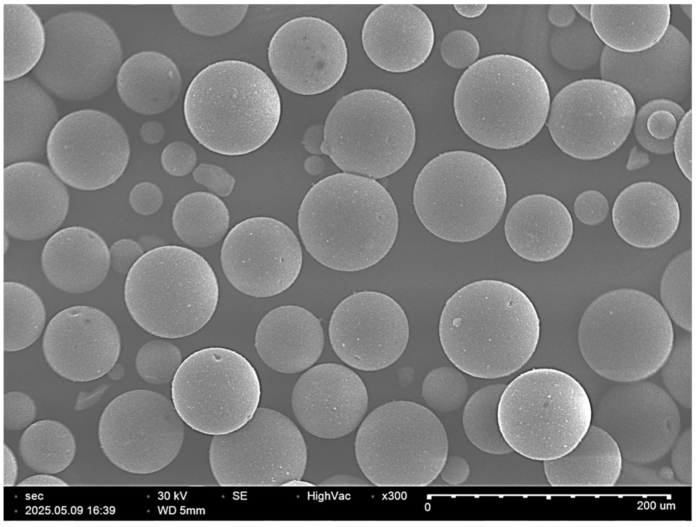
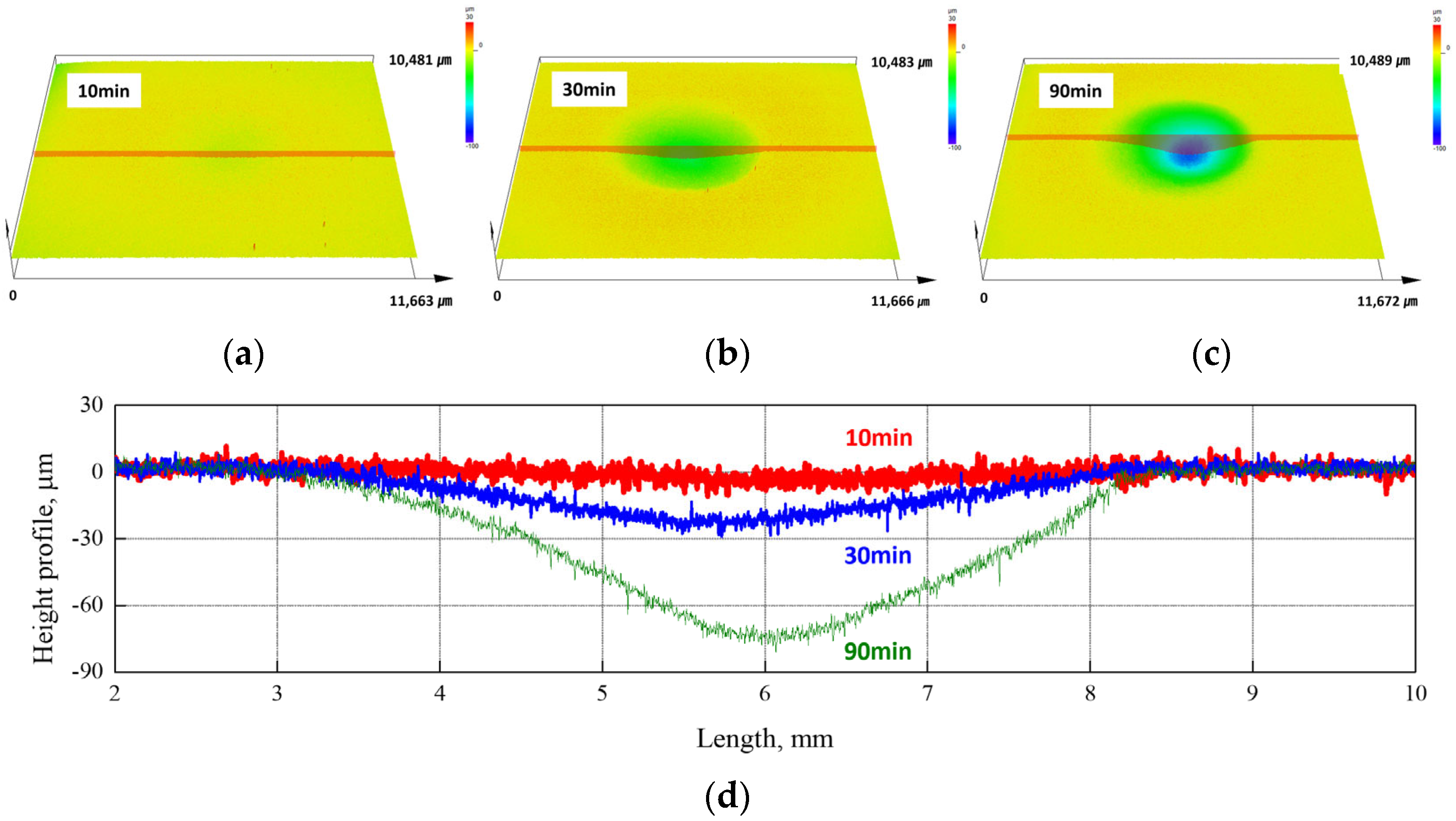
The SPE test revealed plastic deformation with extruded lips on the surface of 316L stainless steel, thereby providing evidence of the surface damage characteristics of ductile materials.
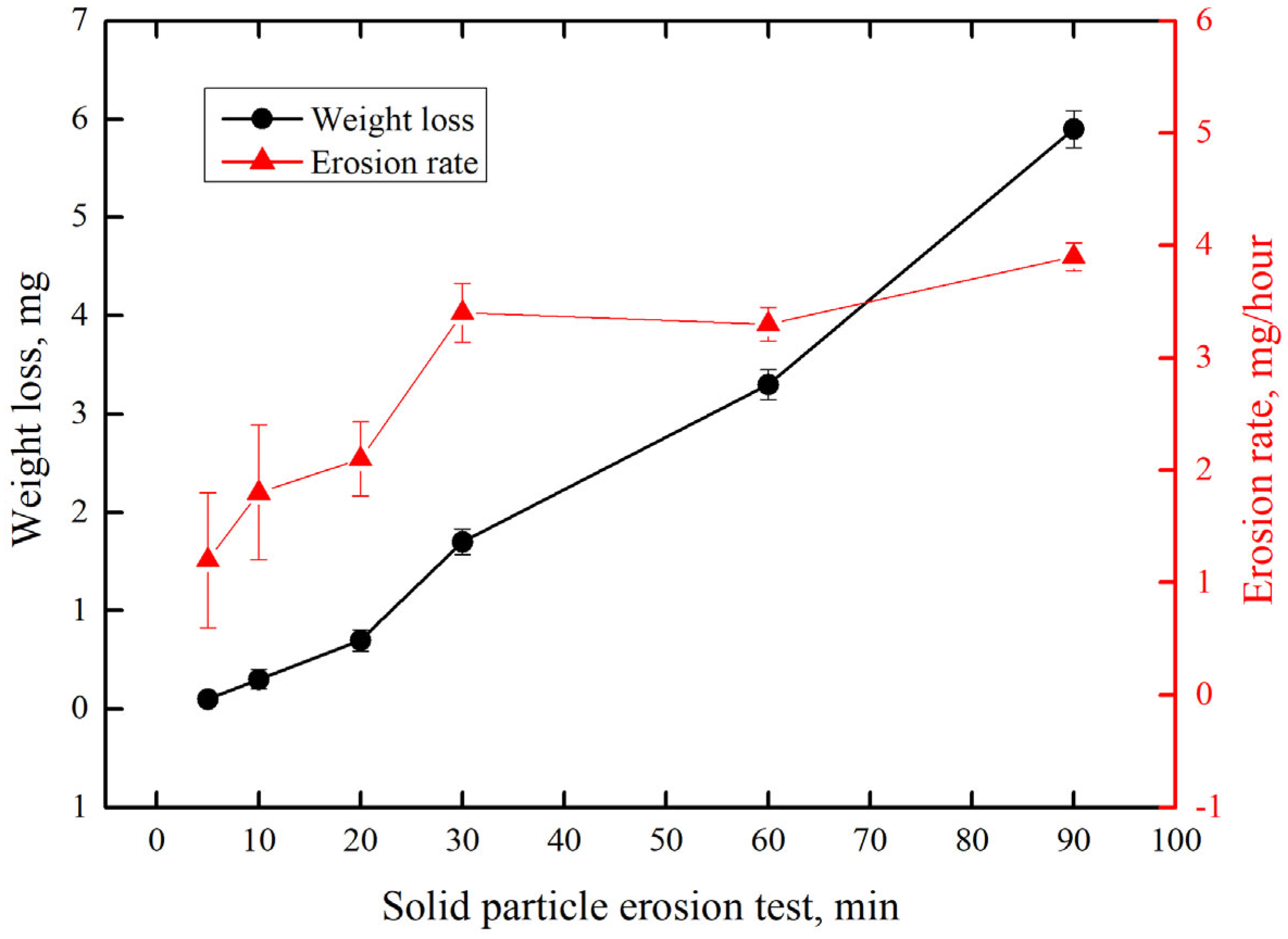
(4)
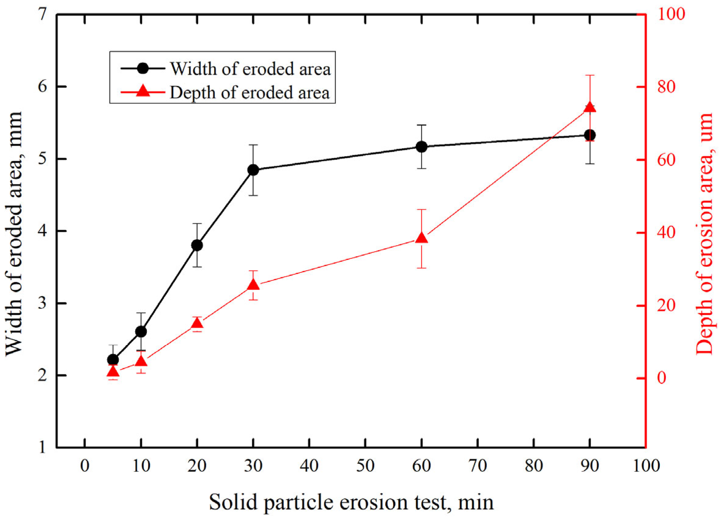
In the early stage of the SPE test, surface damage progressed simultaneously in both width and depth directions, resulting in a sharp increase in the erosion rate. However, in the later stages, damage occurred predominantly in the depth direction, and the erosion rate increased more gradually.
(5)
The surface damage characteristics caused by SPE were significantly influenced by test parameters such as particle shape, nozzle diameter, stand-off distance between the nozzle and the material, and impact angle.
(6)
Fatigue analysis allowed for the assessment of fatigue damage distribution on the nozzle ring blades caused by thermal degradation, while the SPE test provided insights into the expected surface damage patterns. Furthermore, understanding the trend of fatigue damage is expected to contribute to predicting the progression direction and characteristics of fractures and cracks in the nozzle ring blades.
(7)
In this study, the results of the fatigue analysis and SPE damage evaluation of the turbocharger nozzle ring have limitations in fully replicating the actual operating conditions of the turbocharger. To address these limitations, future work should incorporate computational fluid dynamics analysis under SPE conditions and validate the simulation results by comparing them with actual damage cases observed in turbocharger nozzle rings.

Author Contributions

Conceptualization, I.-C.P.; methodology, W.-S.J. and I.-C.P.; software, W.-S.J. and I.-C.P.; validation, W.-S.J. and I.-C.P.; formal analysis, W.-S.J. and I.-C.P.; investigation, W.-S.J. and I.-C.P.; resources, W.-S.J. and I.-C.P.; data curation, W.-S.J. and I.-C.P.; writing—original draft preparation, W.-S.J. and I.-C.P.; writing—review and editing, I.-C.P.; visualization, W.-S.J. and I.-C.P.; supervision, I.-C.P.; project administration, W.-S.J. and I.-C.P.; funding acquisition, I.-C.P. All authors have read and agreed to the published version of the manuscript.

Funding

This research received no external funding.

Data Availability Statement

The data presented in this study are available on request from the corresponding author. The data are not publicly available due to the project requirements.

Conflicts of Interest

The authors declare no conflicts of interest.

References

  1. Andersson, N.; Kisbenedek, E. Review on Recent Advances for Marine Turbocharger Technologies for Two-stroke Diesel Engines. Bachelor’s Thesis, Chalmers University of Technology, Gothenburg, Sweden, 2018. [Google Scholar]
  2. Hong, S.U. Developing Trends of Super-charger for Large Size Marine Diesel Engine. J. Adv. Mar. Eng. Technol. 1986, 10, 91–100. [Google Scholar]
  3. Bhardwaj, S.; Buke, Y. Computational Fluid Dynamics Analysis of A Turbocharger System. Int. J. Sci. Res. 2012, 3, 161–164. [Google Scholar] [CrossRef]
  4. Anantharaman, M.; Islam, R.; Sardar, A.; Garaniya, V.; Khan, F. Impact of Defective Turbocharging System on the Safety and Reliability of Large Marine Diesel Engine. Int. J. Mar. Navig. Saf. Sea Transp. 2021, 15, 189–194. [Google Scholar] [CrossRef]
  5. Chybowski, L.; Jakubowski, A.; Żółkiewski, S. Analysis of the Relationship between Selected Ship and Propulsion System Characteristics and the Risk of Main Engine Turbocharger Explosion. J. Mar. Sci. Eng. 2023, 11, 360. [Google Scholar] [CrossRef]
  6. Kneževic, V.; Orovic, J.; Stazic, L.; Culin, J. Fault Tree Analysis and Failure Diagnosis of Marine Diesel Engine Turbocharger System. J. Mar. Sci. Eng. 2020, 8, 1004. [Google Scholar] [CrossRef]
  7. Lus, T. Marine Diesel Engines Turbochargers Diagnostic Methods. Appl. Struct. Health Usage Cond. Monit. 2012, 3, 49–54. [Google Scholar]
  8. Popov, D. Turbocharger Breakdown Investigation. Sci. Bull. Nav. Acad. 2022, XXV, 106–114. [Google Scholar] [CrossRef]
  9. Hafidz, M.L.; Wibowo, T. Analysis of Blade Turbine Damage in Turbocharger System in PLTD Diesel Engine. J. Phys. Conf. Ser. 2020, 1477, 052029. [Google Scholar] [CrossRef]
  10. Hwang, S.J.; Lee, M.G.; Jung, J.W.; Kwon, S.K.; Lee, C.M. A Study on the Development of Marine Turbocharger Nozzle Ring using Investment Casting. J. Korean Soc. Precis. Eng. 2014, 31, 671–675. [Google Scholar] [CrossRef]
  11. Phan, V.Q.; Phan, C.T. Study on the Effect of Changing Hull Resistances to Turbocharger Operation of Marine Diesel Engine. In Proceedings of 19th Annual General Assembly (AGA) of the International Association of Maritime Universities 2018, Barcelona, Spain, 17–19 October 2018. [Google Scholar]
  12. Makke, A.; Kassir, A.; Boughanmi, H.; Seifert, T.; Chang, C.C.; Kallepalli, R. Thermomechanical Fatigue Crack Growth Simulation in a Turbo-Housing Model Using Nonlinear Fracture Mechanics. SAE Technical Paper 2023-01-0596. Available online: https://www.sae.org/publications/technical-papers/content/2023-01-0596/ (accessed on 11 May 2025).
  13. Choi, B.L. Comparison of Thermally Induced Plastic Strains for Integrated Exhaust Manifold-Turbocharger by Considering Parting-Line Effect. J. Korean Soc. Mech. Technol. 2021, 23, 111–116. [Google Scholar]
  14. Zheng, W.; Xing, W.D.; Wang, Z.; Xin, L. Fatigue Reliability Analysis of Turbine of Turbocharger Based on the Endurance Test Profile of Engine. Appl. Mech. Mater. 2012, 215–216, 750–753. [Google Scholar] [CrossRef]
  15. Yi, X.; Wang, Z.; Liu, S.; Hou, X.; Tang, Q. An Accelerated Degradation Durability Evaluation Model for the Turbine Impeller of a Turbine Based on a Genetic Algorithms Back-Propagation Neural Network. Appl. Sci. 2022, 12, 9302. [Google Scholar] [CrossRef]
  16. Park, I.C.; Han, M.S. Solid Particle Erosion Behavior of Inconel 625 Thermal Spray Coating Layers. J. Korean Soc. Mar. Environ. Saf. 2021, 27, 521–528. [Google Scholar] [CrossRef]
  17. Ilieva, G.I. Erosion Failure Mechanisms in Turbine Stage with Twisted Rotor Blade. Eng. Fail. Anal. 2016, 70, 90–104. [Google Scholar] [CrossRef]
  18. Azevedo, C.R.F.; Sinátora, A. Erosion-fatigue of Steam Turbine Blades. Eng. Fail. Anal. 2009, 16, 2290–2303. [Google Scholar] [CrossRef]
  19. Segurab, J.A.; Castroa, L.; Rosalesa, I.; Rodrigueza, J.A.; Urquizaa, G.; Rodriguez, J.M. Diagnostic and Failure Analysis in Blades of a 300 MW Steam Turbine. Eng. Fail. Anal. 2017, 82, 631–641. [Google Scholar] [CrossRef]
  20. Rani, S.; Agrawal, A.K.; Rastogi, V. Failure Analysis of a First Stage IN738 Gas Turbine Blade tip Cracking in a Thermal Power Plant. Case Stud. Eng. Fail. Anal. 2017, 8, 1–10. [Google Scholar] [CrossRef]
  21. Kumar, S.; Kumar, M.; Handa, A. Combating Hot Corrosion of Boiler Tubes—A study. Eng. Fail. Anal. 2018, 94, 379–395. [Google Scholar] [CrossRef]
  22. Firouzeh, A.; Ranjbar, K.; Baghal, S.M.; Kaidan, A.H.; Mohemi, E. Failure Assessment of ASTM A213-T12 Superheater Boiler Tubes in a Natural Gas Liquid Plant. Eng. Fail. Anal. 2018, 89, 15–27. [Google Scholar] [CrossRef]
  23. Vicenzi, J.; Villanova, D.L.; Lima, M.D.; Takimi, A.S.; Marques, C.M.; Bergmann, C.P. HVOF-coatings against High Temperature Erosion (300 C) by Coal Fly Ash in Thermoelectric Power Plant. Mater. Des. 2006, 27, 236–242. [Google Scholar] [CrossRef]
  24. Praveen, A.S.; Sarangan, J.; Suresh, S.; Channabasappa, B.H. Optimization and Erosion Wear Response of NiCrSiB/WC-CO HVOF Coating using Taguchi Method. Ceram. Int. 2016, 42, 1094–1104. [Google Scholar] [CrossRef]
  25. Kim, D.S.; Han, G.S.; Lee, D.K. Recycling of useful materials from fly ash of coal-fired power plant. Clean Technol. 2019, 25, 179–188. [Google Scholar]
  26. Cai, L.; Yao, J.; Hou, Y.; Li, Y.; Wang, S.; Mao, J. Numerical Study on Aerodynamic Performance and Particle Erosion Characteristics of Flue Gas Turbine. Therm. Sci. 2023, 27, 4291–4305. [Google Scholar] [CrossRef]
  27. Xu, W.; Zhu, K.; Wang, J.; Lin, Y.; Li, Q. Modelling and Numerical Analysis of the Effect of Blade Roughness on Particle Deposition in a Flue Gas Turbine. Powder Technol. 2019, 347, 59–65. [Google Scholar]
  28. Gao, X.; Wang, J.; Xia, M.; Jin, Y. Research Progress of Catalysts Fouling in Flue Gas Turbines Used in Catalytic Cracking Unit. China Powder Sci. Technol. 2015, 21, 25–32. [Google Scholar]
  29. Lin, G.Q.; Wang, M.T. Stress and strain Analysis of First Stage Rotating Blades of Flue Gas Turbine Blades. Appl. Mech. Mater. 2012, 130–134, 691–695. [Google Scholar] [CrossRef]
  30. Zheng, L.J.; Song, H.H.; Zhang, H.; Jiang, S.L.; Wang, Q.; Chen, Y.; Wang, D.; An, S. Blades Fracture Failure Analysis of a Certain Flue Gas Turbine. Petro-Chem. Equip. 2018, 6, 74–79. [Google Scholar]
  31. Lee, K.H. Analysis of Horizontal Axis Tidal Turbine Performance and Turbine Efficiency Deficit from Blade Deformation. Ph.D. Thesis, Inha University, Incheon, Republic of Korea, 2016. [Google Scholar]
  32. Jeong, H.C.; Yang, C.J. Variation in Flow Characteristics and Power Performance Due to Axial Distance Optimization in the Design of Counter-Rotating Tidal Turbines. Energies 2024, 17, 3207. [Google Scholar] [CrossRef]
  33. ASTM G76-05; Standard Test Method for Conducting Erosion Tests by Solid Particle Impingement Using Gas Jets. American Society for Testing and Materials International: West Conshohocken, PA, USA, 2017.
  34. Walker, C.I.; Robbie, P. Comparison of Some Laboratory Wear Tests and Field Wear in Slurry Pumps. Wear 2013, 302, 1026–1034. [Google Scholar] [CrossRef]
  35. Singh, J.; Kumar, S.; Mohapatra, S.K. Tribological Analysis of WC-10Co-4Cr and Ni-20Cr2O3 Coating on Stainless Steel 304. Wear 2017, 376, 1105–1111. [Google Scholar] [CrossRef]
  36. Neilson, J.H.; Gilchrist, A. Erosion by a Stream of Solid Particles. Wear 1968, 11, 111–122. [Google Scholar] [CrossRef]
  37. Mellali, M.; Grimaud, A.; Leger, A.C.; Fauchais, P.; Lu, J. Alumina Grit Blasting Parameters for Surface Preparation in the Plasma Spraying Operation. J. Therm. Spray Technol. 1992, 6, 217–227. [Google Scholar] [CrossRef]
  38. Jung, K.H.; Kim, S.J. Effect of various factors on solid particle erosion behavior of degraded 9Cr-1MoVNb steel with experiment design. Appl. Surf. Sci. 2020, 506, 144956. [Google Scholar] [CrossRef]
  39. Chen, Q.; Li, D.Y. Computer simulation of solid particle erosion. Wear 2003, 255, 78–84. [Google Scholar] [CrossRef]
  40. Levy, A.V.; Chik, P. The effects of erodent composition and shape on the erosion of steel. Wear 1983, 89, 151–162. [Google Scholar] [CrossRef]
Figure 1. Descriptions of turbocharger parts.
Jmse 13 01230 g001
Figure 2. Configuration of finite element model for nozzle ring: (a) three-dimensional model and (b) meshing model.
Jmse 13 01230 g002
Figure 3. Boundary condition for nozzle ring.
Jmse 13 01230 g003
Figure 4. Schematic diagram of solid particle erosion apparatus.
Jmse 13 01230 g004
Figure 5. SEM micrograph showing the morphology of SiO2 solid particle.
Jmse 13 01230 g005
Figure 6. Variation in scavenging air pressure and before T/C exhaust gas temperature by engine speed.
Jmse 13 01230 g006
Figure 7. Surface pressure coefficient contours at engine load 100%: (a) inlet and (b) outlet.
Jmse 13 01230 g007
Figure 8. Mesh dependency test.
Jmse 13 01230 g008
Figure 9. Results of fatigue analysis on the nozzle ring blade fraction: (a) configuration of the nozzle ring and cross-section of the blade; (b) blade deformation; and (c) equivalent stress.
Jmse 13 01230 g009
Figure 10. Distribution contours on nozzle ring blade: (a) fatigue life and (b) fatigue damage.
Jmse 13 01230 g010
Figure 11. Results of fatigue analysis by engine speed.
Jmse 13 01230 g011
Figure 12. Results of 3D analysis after solid particle erosion test during 10 min, 30 min, and 90 min: (ac) 3D image and (d) surface profile.
Jmse 13 01230 g012
Figure 13. Width and depth of eroded area after solid particle erosion test.
Jmse 13 01230 g013
Figure 14. Weight loss and erosion rate after solid particle erosion test.
Jmse 13 01230 g014
Figure 15. SEM image and EDS analysis results of the fly ash.
Jmse 13 01230 g015
Figure 16. XRD of the fly ash.
Jmse 13 01230 g016
Figure 17. SEM micrographs showing the surface morphology after solid particle erosion test: (a) during 5 min; (b) during 90 min.
Jmse 13 01230 g017
Table 1. Mechanical properties of the nozzle ring.
PropertyValue
Specific heat0.5 (J/g °C)
Specific gravity7.93
Coefficient of thermal expansion17.3 W/m °C
Thermal conductivity16.3 W/m °C
Yield strength≥175 N/mm2
Tensile strength≥480 N/mm2
Elongation≥40%
Table 2. Chemical composition for 316L stainless steel (wt.%).
GradeNiCrMoCSiMnPSCuNFe
316L10.1716.92.010.0220.611.030.0330.0290.2810.011Balance
Table 3. Detailed condition for SPE test.
FactorUnitValue
Erodent sizeμmabout 50
Erodent feed rateg/min2
Air pressurekg/cm22
Nozzle diametermm3.6
Stand-off distancemm10
Impact angle°90
Temperature°CRoom temperature
Disclaimer/Publisher’s Note: The statements, opinions and data contained in all publications are solely those of the individual author(s) and contributor(s) and not of MDPI and/or the editor(s). MDPI and/or the editor(s) disclaim responsibility for any injury to people or property resulting from any ideas, methods, instructions or products referred to in the content.

