Abstract
A tightly coupled hybrid monocular visual SLAM system for unmanned underwater vehicles (UUVs) is introduced in this paper. Specifically, we propose a robust three-step hybrid tracking strategy. The feature-based method initially provides a rough pose estimate, then the direct method refines it, and finally, the refined results are used to reproject map points to improve the number of features tracked and stability. Furthermore, a tightly coupled visual hybrid optimization method is presented to address the inaccuracy of the back-end pose optimization. The selection of features for stable tracking is achieved through the integration of two distinct residuals: geometric reprojection error and photometric error. The efficacy of the proposed system is demonstrated through quantitative and qualitative analyses in both artificial and natural underwater environments, demonstrating excellent stable tracking and accurate localization results.
1. Introduction
Unmanned underwater vehicles (UUVs), including autonomous underwater vehicles (AUVs) and remotely operated vehicles (ROVs), with their intelligent and convenient characteristics, have significant potential in ocean engineering [1], marine science [2], and underwater remote sensing [3]. The necessity for UUVs to ascertain precise position estimates during deployment, operation, and recovery constitutes a pivotal safeguard for the execution of missions. As the diversity of underwater missions continues to increase, more advanced navigation and localization techniques are becoming a prime concern [4].
It has been established that electromagnetic signals experience a rapid attenuation in water. As a result, radio positioning technology, which is widely used on land, faces significant limitations in underwater environments. In recent years, rapid advancements in artificial intelligence and the manufacturing industry have driven the development of simultaneous localization and mapping (SLAM) technology, enabling autonomous navigation of mobile robots. This has resulted in SLAM technology becoming a current research trend in the field of UUV. The camera features a simple structure, low cost, and high visibility, making it one of the essential sensors for UUVs [5,6]. However, in most underwater missions, the camera is used primarily for capturing images or video, with its positioning capabilities underutilized. The visual SLAM technique, by analyzing the information extracted from the camera images, allows the recovery of the camera’s motion in a local map of its surroundings while constructing a map of the environment. Upon revisiting a previously captured image area, the system identifies loop closures and rectifies the accumulated drift error.
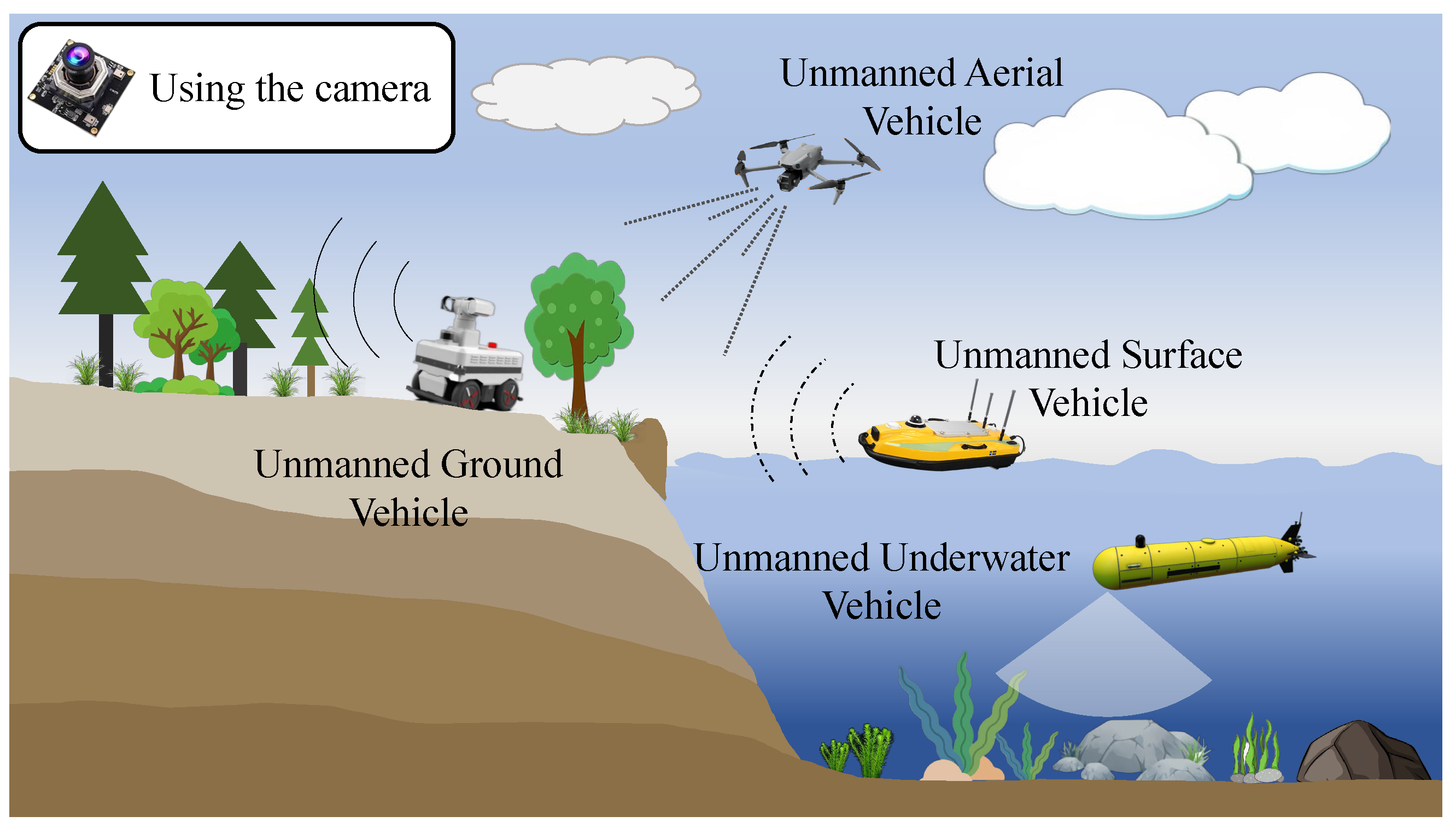
Visual SLAM is employed for remote sensing and perception of various unmanned vehicles, as illustrated in Figure 1. It is most widely used in unmanned ground vehicles (UGVs) [7], unmanned aerial vehicles (UAVs) [8], and unmanned surface vehicles (USVs) [9], demonstrating superior performance. However, in harsh underwater environments such as turbidity, backscatter, and unstable illumination, the image quality captured by the camera is significantly lower than in air, resulting in inaccurate positioning or even failure of underwater visual SLAM.
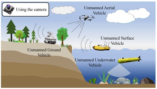
Figure 1.
Visual SLAM is used for remote sensing and perception in different types of unmanned vehicles.
The front-end and back-end are the two parts that make up the visual SLAM system. The front-end is also referred to as visual odometry (VO). The purpose of VO is to give good initial values for the back-end by estimating the approximate camera motion based on information obtained from the adjacent images. VO algorithms can be classified into two primary groups. Feature-based (or indirect) methods minimize the geometric reprojection error by matching previously estimated repeatable features to recover the camera pose and scene structure. Image features (e.g., points, lines, edgelets) are robust to initial conditions and can be tracked reliably under certain levels of illumination and viewpoint changes. However, in low-texture scenes with sparse features, tracking can easily fail, which may lead to system failure.
Conversely, direct methods leverage the entirety of the available data in an image by operating on the original pixels. The method jointly estimates motion and correspondence by minimizing the photometric error, i.e., the difference in intensity between corresponding pixels in the image. However, direct methods suffer from a significant degree of non-convexity [10], which limits the types of operations they can handle accurately when predicting camera motion.
The feature-based VO method, with its advantages in stability and insensitivity to light and dynamic objects, has long been considered the mainstream. However, direct VO can use non-corner pixels and even smooth image regions as long as there is sufficient gradient information, demonstrating better robustness, particularly when the image lacks well-defined corner features [11]. Rolling shutter effects, sensor asynchrony, and calibration errors are more problematic in direct methods than in feature-based ones. Furthermore, since the direct method does not rely on discrete features, performing correspondence matching between images at different locations is difficult. Consequently, loop closure detection is usually difficult.
The hybrid approach, a recently developed VO solution, leverages the benefits of both direct and indirect formulations to achieve optimal performance. Given the challenges posed by underwater scenes, we propose a new tightly coupled hybrid monocular visual SLAM for UUVs. A three-step hybrid enhancement tracking method is proposed to address the loss of underwater feature tracking. In summary, the feature-based method is first employed to obtain an approximate pose estimate, followed by the direct method to refine the pose. Ultimately, the refined pose is used to reproject the map points, enhancing the number of tracked features. The combination of indirect methods’ resilience to large-scale motion and direct methods’ sub-pixel accuracy and robustness to texture-deficient environments has the potential to further enhance underwater VO stability. Furthermore, a tightly coupled visual hybrid optimization method is proposed to address inaccurate back-end pose optimization. In essence, the local window is used for optimization, with stably tracked features selected to construct the reprojection residual and surrounding pixel blocks used for the photometric residual. The hybrid optimization of these tightly coupled residuals exploits the respective advantages of the feature-based and direct methods, enhancing odometry accuracy. Overall, the contribution of this paper can be summarized as follows:
- 1.
- A robust three-step hybrid tracking strategy is proposed. Feature tracking is used to obtain an initial rough pose that converges, and the direct method is then employed for rapid sparse refinement. The ultimate goal is to achieve accurate pose estimation between adjacent frames and reproject the map points to enhance both the number and stability of feature tracking.
- 2.
- Using reliably tracked features, a tight coupling hybrid visual optimization method is proposed. Robust features are used to jointly optimize two residuals: the reprojection error and the photometric error. This method tightly couples the hybrid VO and mapping processes, improving localization and mapping accuracy.
- 3.
- A tightly coupled hybrid monocular SLAM framework for underwater scenes, named UTH-SLAM, is constructed. The tracking stability and localization accuracy of the system are demonstrated using publicly available high-precision underwater datasets and natural underwater data.
2. Related Work
The feature-based method is considered the most prominent in VO, primarily using corners, edges, and blocks in the image as features. It performs geometric bundle adjustment (BA) to minimize reprojection error. Underwater scenarios introduce new challenges for feature-based methods compared to their high performance on land. In underwater visual SLAM, the fundamental matrix is used to improve feature matching robustness by removing false matches that SIFT [12] does not detect [13]. To overcome the limited number of descriptors extracted by SURF [14], Aulinas et al. [15] combined image processing techniques to identify the region of interest and applied SURF feature extraction and matching within this region. Salvi et al. [16] proposed extracting a mixture of SIFT and SURF features from images to achieve a dynamic trade-off between the number of features, robustness, and computational complexity.
ORB [17] features are among the top-performing methods on land, with the ORB-SLAM family [18,19,20] as the representative system. It enhances FAST [21] corners by adding principal directions and rotationally invariant properties to the BRIEF [22] descriptors. It is increasingly used in underwater VO due to its fast feature processing speed and more stable rotational invariance. Xu et al. [23] combined ORB features with object features to improve the robustness of underwater navigation and generate a detailed semantic map. An underwater stereo matching method combining ORB-based feature detection and curve constraints further enhances the high-speed processing capability of underwater binocular vision systems [24].
The direct method, based on the theory of greyscale invariance, has been studied. It estimates camera motion based on pixel luminance, avoiding the computation of descriptors and feature matching. Unlike most feature-based methods, the direct method analyzes the entire image and can produce sparse, semi-dense, or dense maps, depending on the task requirements. DSO [10] is one of the best-performing direct odometry systems, utilizing photometric BA to co-optimize camera motion and inverse depth of sparse points in a sliding window mode. This is the first investigation into the effect of photometric calibration on the system using a direct approach. However, DSO suffers from drift over time. As a pure odometry method, the resulting map points are not described, and therefore, cannot be reused or incorporated into a closed-loop system. Xia et al. [25] proposed a scale-aware monocular odometry system based on DSO and applied it to underwater environments. They obtained the absolute scale by aligning the mesh model with a real fishnet, while estimating the vehicle’s pose in the fishnet detection system.
The feature-based method is more challenging to track in low-texture scenes. The greyscale invariance assumption in the direct method is highly sensitive to lighting and less resilient to geometric distortion. Recent studies have explored the combination of feature-based and direct methods in SLAM. However, these methods have typically been loosely coupled at different stages of the pipeline. SVO [26] is a well-known hybrid method. It tracks the aligned image with FAST corner features and minimizes photometric error in the surrounding patches. The scene structure and motion are then jointly optimized through reprojection errors. Gao et al. [27] introduced a loop closure pipeline to the DSO system, termed LDSO. They proposed using both corners and pixels as direct factors, contributing photometric residuals but not geometric residuals. Separate ORB descriptors are computed exclusively for corners for loop closure detection. Yu et al. [28] proposed combining reprojection and photometric residuals for joint optimization. However, these two residuals are treated as independent entities, requiring separate processes to extract and maintain each. Additionally, the optimization process does not incorporate key a priori information of the residuals, and hybrid residuals are treated as a black box.
ORB-SLAM and DSO are loosely coupled [29], with DSO acting as a fast and robust tracker, while ORB-SLAM further refines the marginalized keyframe poses. In their work, the direct and feature-based methods run in two separate parallel threads, maintaining respective global sparse feature mapping and local semi-dense mapping, which reduces system efficiency to some extent. Additionally, geometric residuals are not used in real-time odometry unless loop closure is detected, which further constrains the global consistency of the system. This loosely coupled strategy benefits from the resilience of the direct approach in low-texture scenes. It also benefits from a global map maintained through feature modules. However, since the direct method operates independently, the feature-based method’s ability to handle illumination changes and unsteady motion is not fully exploited. For example, if there is a large change in illumination, the direct adjustment can severely affect the pose estimation and the subsequent feature-based estimation cannot be recovered.
Feature-assisted direct monocular odometry, which invokes the indirect method only when direct tracking fails to sustain the system, was proposed by Younes et al. [30]. In further research [31], they proposed simultaneously extracting two types of features, i.e., salient corner features and pixel features, and coupling photometric and geometric information into a unified formulation for robust tracking. Experiments show that this tightly coupled structure performs well on photometrically calibrated datasets. However, this work does not reuse reconstructed maps and does not demonstrate performance on general datasets, such as those with dynamic motion patterns or illumination changes.
In underwater environments, uneven illumination and low texture present severe challenges to vision SLAM. Ding et al. [32] mitigated vision-only limitations by fusing IMU and depth measurements and introducing hybrid visual residuals to improve the accuracy of underwater multi-sensor fusion localization. Miao et al. [33] proposed a robust data association and a unified optimization method to enhance the stability of visual-inertial odometry in underwater scenes. However, computing projection and photometric errors for all features of binocular images imposes significant computational overhead on the system. Unlike the aforementioned underwater hybrid approach, this work focuses on applying the hybrid approach to the tracking module and the tightly coupled optimization of two types of residuals at the back-end. Additionally, to reduce computational overhead when constructing the photometric error, we select only features tracked beyond a certain threshold, rather than using all tracked features. This is because these features are more stable, their depth information is known after multiple tracking optimizations, and they can, therefore, play a greater role in the optimization process.
3. The Framework of UTH-SLAM
3.1. System Overview
Inspired by the current best-performing feature-based ORB-SLAM3 [20] and direct-method-based DSO [10] systems, we combine them and introduce several modifications. Figure 2 illustrates the framework of the proposed system, which consists mainly of three parallel threads: the tracking thread, the local mapping thread, and the loop closing thread. Based on both direct and indirect methods, the modules highlighted in the green box represent the main contributions of this paper: the hybrid tracking strategy, the failure recovery module, and the local hybrid optimization algorithm.
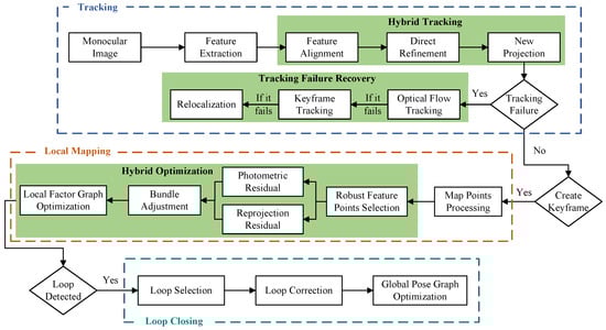
Figure 2.
Underwater tightly coupled hybrid monocular visual SLAM framework, named UTH-SLAM.
The frames captured by the monocular camera are initially fed into the system. While extracting the ORB features, an image pyramid is constructed to increase their scale invariance. The distribution of the features is then optimized using a quadtree-based feature extraction algorithm. A three-stage hybrid tracking method is employed to enhance the stability of continuous inter-frame tracking. If the track is lost, it enters the failure recovery module, which attempts to recover the track in three distinct ways. Once the tracking process is complete, the frame with the best tracking performance is selected as the keyframe, serving as the anchor frame for nearby frames. Keyframes play a crucial role in ensuring trajectory accuracy; therefore, they are further optimized in the local mapping thread.
To ensure real-time performance, the local mapping thread runs only when a new keyframe is entered. The local factor graph optimization window also enhances system efficiency. BA is performed for multiple keyframes within the window and the map points visible to the keyframes. Hybrid visual residuals are constructed using stable tracking features, incorporating both reprojection and photometric residuals. This tight coupling fully exploits both benefits to enhance the optimization accuracy. In the loop closing thread, global map reuse is achieved by computing descriptors for ORB features. DBoW2 [34] is employed to accelerate the search for loop closure candidate keyframes. Upon completion of loop verification, loop correction and global pose graph optimization are performed.
Throughout this paper, matrices are represented by bold uppercase letters and vectors by bold lowercase letters. and represent values in the world and camera coordinate systems, respectively. and denote the special Euclidean and orthogonal groups, respectively. As shown in Equation (1), the transformation from the camera frame to the world frame is represented by the transformation matrix , where is the rotation matrix and is the translation vector. A rigid transformation with scale is also indicated by . The intensity image is indicated by , with denoting the image domain. The camera projection function is represented by , and the back-projection by .
3.2. Tracking Thread
3.2.1. Feature Extraction
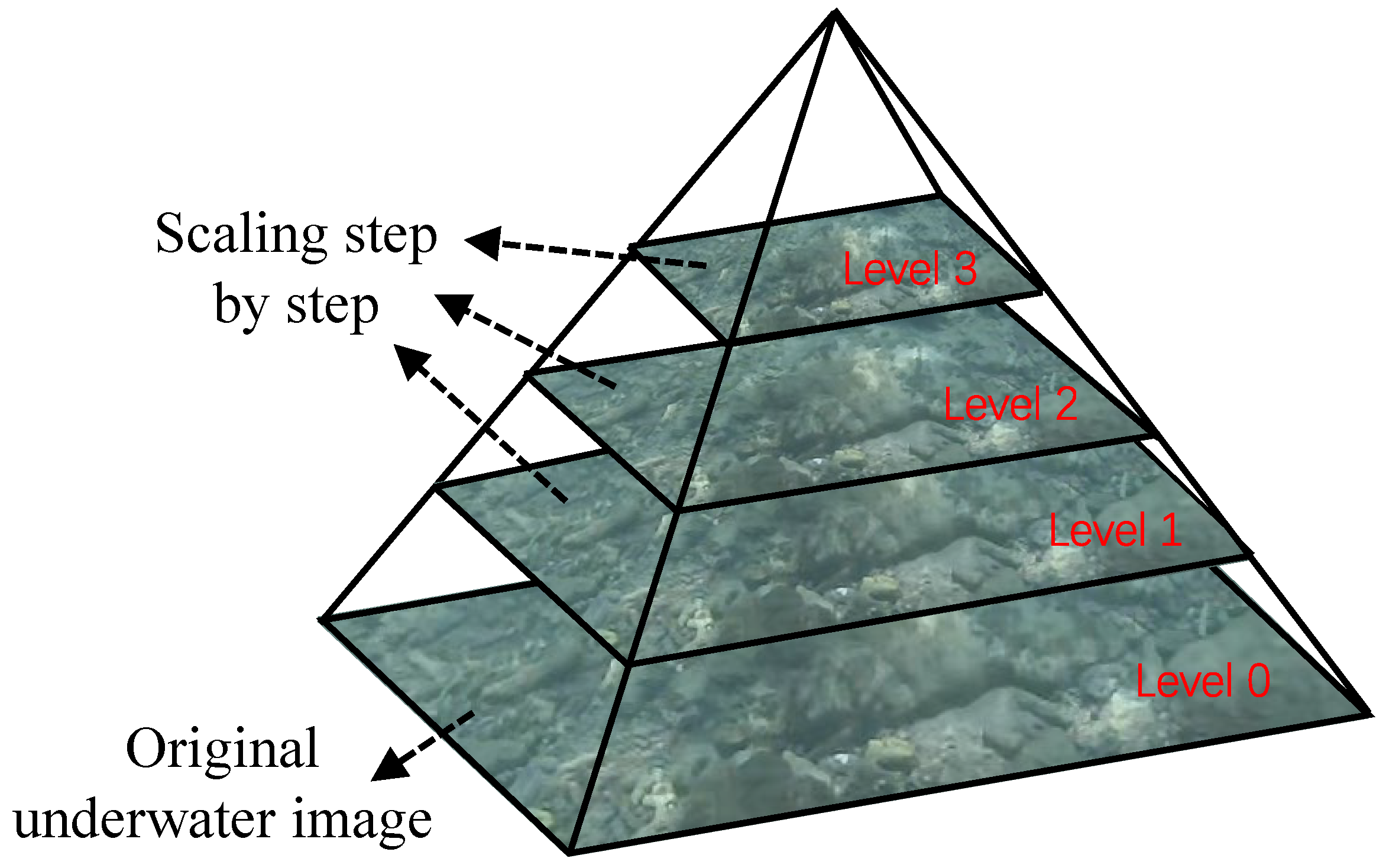
To improve the scale invariance of the features, the underwater images are scaled by a fixed percentage after acquisition. As shown in Figure 3, the original underwater image is used as the base layer, which is then progressively scaled to construct the image scale pyramid. ORB features are extracted at each pyramid level. As the number of pyramid layers increases, the resolution decreases, the corresponding image area becomes smaller, and fewer features need to be extracted.
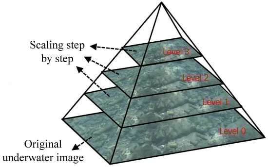
Figure 3.
Underwater image scale pyramid.
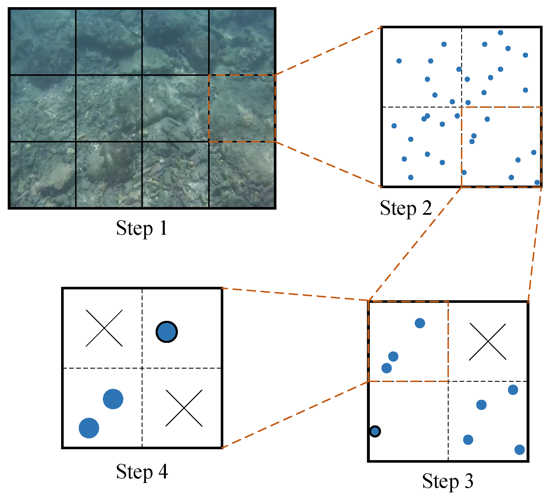
A quadtree-based feature extraction algorithm is used for each layer, and its segmentation process is shown in Figure 4. First, an initial node division is performed based on the aspect ratio of the image, assuming that the image is divided into 12 nodes in the first step. If a node has more than one feature, it is split into four new nodes, as shown in the second step. This process is repeated, with quad splitting performed continuously. If there are no features within a node, the node is deleted, as illustrated by the top-right corner in step 3. If there is only one feature within a node, as shown by the bottom-left corner in step 3 and the top-right corner in step 4, the node is marked as unsplittable, and this single feature is extracted. When the total number of nodes reaches or exceeds a predetermined threshold, no further segmentation is performed. If multiple features remain within a node, as seen in the bottom-left corner of step 4, only the feature with the largest response value is retained.

Figure 4.
The splitting process of the quadtree-based feature extraction method.
Using this feature selection method, clustering can be avoided and features are evenly distributed. By reducing feature accumulation in local areas, the image’s information representation is improved, which is crucial for feature tracking, pose estimation, and loop closure detection.
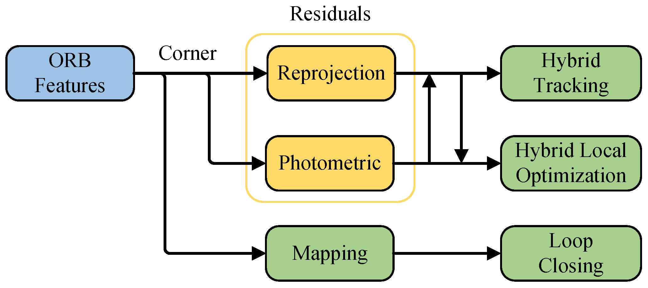
Figure 5 shows that in the proposed UTH-SLAM system, only ORB features are extracted. Using this single feature type, a hybrid tracking approach combining feature-based and direct methods is proposed. This strategy reduces the complexity of simultaneously extracting two feature types while improving system stability. During the local optimization process, reprojection and photometric errors are minimized simultaneously using robust features. Localization accuracy is improved by tightly coupling two distinct visual residuals. Another key function of ORB is mapping. The proposed system describes features to enable global map reuse, facilitating loop closure detection.

Figure 5.
Application process of ORB features.
3.2.2. Hybrid Tracking Algorithm
The initialization of the monocular odometry system starts with matching 2D features between two images, completing pose estimation using polarimetric geometry, and then using the pose to triangulate 3D map points. There is some scaling ambiguity in the information provided by the monocular odometer, as the monocular system is unable to estimate the depth of the map points accurately. Once initialization is complete, 3D–2D tracking, and pose estimation commence.
Stable tracking between adjacent frames is critical to ensure the continuous operation of the system. Feature-based tracking is more stable for large movements and lighting changes, but is prone to tracking loss when encountering low-texture scenes. Direct alignment techniques compensate for this shortcoming. Therefore, we propose a three-stage hybrid tracking strategy, which combines the advantages of feature-based and direct methods to improve tracking performance.
(1) Feature alignment
Assuming that the camera moves at a constant velocity between adjacent frames, the pose and velocity of the reference frame i at a specific time step can be used to estimate the pose of the current frame j. Based on the estimated pose, the 3D map points of the previous frame are projected onto the current frame, and the search for matching features within a small range is accelerated. The camera pose is optimized by minimizing the geometric reprojection error relative to the positions of a set of 3D points on the map. For the current frame j, the reprojection error between the features and a 3D map point l projected onto frame j can be defined as:
where is the pixel coordinate of the feature pair obtained by matching the map point l to frame j. is the pixel coordinate obtained by projecting l onto frame j using the known camera pose and the coordinates of the map point l.
Thus, the total reprojection error can be found under the cluster L of map points observed in the current frame j:
where is the robust kernel function used to mitigate the effect of mismatched features and denotes the covariance matrix of the reprojection error, derived from the measurement error and noise model. The information matrix, being the inverse of the covariance matrix, quantifies the confidence level of the observations and directly influences the weight of each observation in the optimization process. More detailed explanation of the covariance matrix can be found [35]. represents the pose of the current frame, which is the optimization objective in this step. The constant velocity model tracking provides a rough pose estimate. This estimate is used directly for feature depth estimation, as well as for pose estimation in the next frame, which is not further optimized until a new keyframe is generated. The rough pose also negatively impacts stable feature tracking.
(2) Direct refinement
We perform fast direct sparse refinement on the rough estimates provided by the feature-based tracker. Notably, in the system’s implementation, direct refinement is applied to every frame and is not limited to keyframes. This approach enhances tracking stability and improves pose estimation accuracy between adjacent frames. We believe that the previous step’s results provide an initial estimate, which enables the direct formulation to converge quickly. Additionally, pixels that violate the photometric invariance assumption due to occlusion or illumination changes can be easily identified as outliers. This strategy allows the direct method to converge in fewer iterations and helps avoid local optima.
For every feature with known depth on reference frame i, its predicted location on current frame j can be calculated by the following equation.
where denotes the corresponding 3D map point coordinates in the reference frame, given the known pixel position of feature and its inverse depth. The transformation from frame i to frame i is represented by .
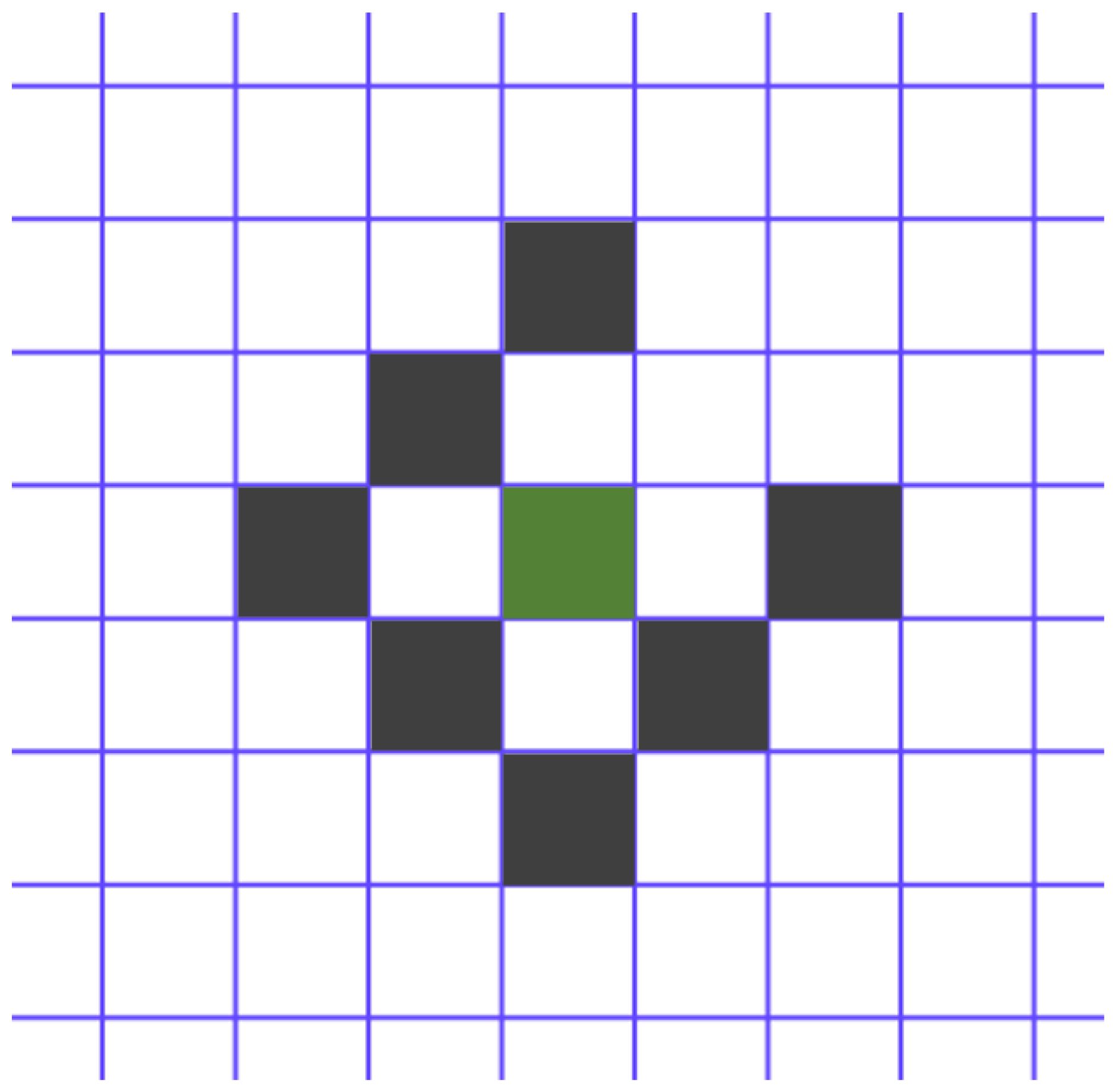
The photometric residual pattern is obtained from previous research [10]. represents the local pixel block, consisting of eight pixels as shown in Figure 6. The current feature is highlighted in green, while the seven neighboring pixels are shown in black. These eight pixels are arranged in a slightly dispersed row and share depth information.
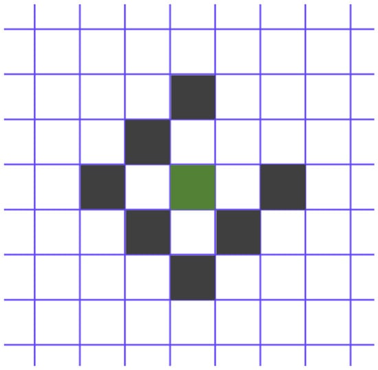
Figure 6.
Photometric residual pattern.
Based on the photometric invariance assumption, the photometric residual is constructed by:
where denotes the luminance function. In the context of grayscale image processing by the algorithm, luminance is defined as the grayscale value of a specific pixel. is a gradient-dependent weight that uses a constant c to decrease the weight of high gradient pixels. Therefore, for a set of features in a reference frame i, the photometric residuals between adjacent frames can be derived:
where is the covariance matrix of the photometric error. The pose of current frame is refined in this step.
(3) New projection for tracking
An important step is proposed. For features in the reference frame i from the first step that have not yet been matched, if they are successfully tracked in the second step, ORB features and descriptors are extracted for the tracked pixels in the current frame j. This step increases the number of potential matching features. Finally, using the refined pose from the second step, the 3D map points from the reference frame are re-projected onto the current frame to obtain more matches. This strategy increases the number of tracked features, thereby improving tracking stability.
Although the proposed hybrid tracking algorithm inevitably increases the tracking time, the second step of direct refinement benefits from a reliable initialization, which allows the direct method to converge with fewer iterations and better control of the computational cost by limiting the features to sparse alignment on the optimal image plane. Using estimates from direct refinement provides better initial values for local optimization and also leads to more matches between adjacent frames. This strategy naturally preserves the robustness of salient features against scene differences and motion patterns while improving tracking accuracy through sub-pixel alignment.
3.2.3. Tracking Failure Recovery Module
As demonstrated in the preceding section, the direct method is used to refine the pose estimates and increase the number of matched features, thereby enhancing tracking stability. Unlike previous studies [29,31] that treated the direct method as a standalone tracking technique, our approach is sensitive to untextured scenes. To maintain the system’s operation, the following recovery strategy is applied in case of feature tracking failure.
(1) First, fast sparse optical flow tracking is performed.
The present study is based on the principles of the Lucas–Kanade optical flow theory [36]. The objective is to determine the correspondence of features from the latest reference frame i to the lost current frame j. Assuming the coordinate of a feature in the frame is denoted by , the image constraint equation can be obtained according to the assumption of grayscale invariance:
In this formula, denotes the luminance value of point at time t. After time , the feature is displaced by and distances along the two axes, respectively. The function at point is expanded using Taylor’s formula:
The final term constitutes the higher-order residual term of Taylor’s formula, which can be assumed to be 0. Equations (8) and (9) are obtained by means of association:
where and represent the velocity components of the pixel point along the x and y directions, denoted u and v, respectively. , , and represent the gradients of luminance, denoted , , and , respectively. Consequently, Equation (10) can be expressed as follows:
and can be calculated from the current frame and from the difference between the two frames. This leaves only the unknown u and v. The pixel coordinates of multiple feature points are used to determine the velocity vector of the optical flow. This is achieved by applying the least squares method to establish the correspondence between the reference frame and the current frame. If a sufficient 3D–2D correlation is found, a motion-only photometric bundle BA is performed. Upon successful pose estimation, the system switches back to its standard tracking mode.
(2) If the previous step fails, keyframe tracking is activated.
Due to the significant temporal discrepancy between the final keyframe and the current frame, both the constant velocity model and the photometric invariance assumption are no longer valid. The current frame undergoes feature extraction and descriptor computation, and the bag-of-words (BoW) algorithm is employed to accelerate the 2D feature matching between the current and reference frames. If the number of matches exceeds a threshold, the correspondence between the keyframe’s 2D features and 3D map points is used to establish the matching relationship between the current frame’s 2D features and the keyframe’s 3D map points. The pose of the previous frame serves as the initial estimate, and the 3D–2D reprojection error is minimized to optimize the current frame’s pose. If more inliers remain after optimization, keyframe tracking is considered successful.
(3) If the previous step fails, the re-localization module is activated.
A group of candidate keyframes similar to the current frame is selected based on the BoW feature vector of the current frame. The matching relationship between the candidate keyframes and the current frame is determined using BoW. The random sample consensus (RANSAC)-based algorithm [37] employs the MLPnP [38] principle to estimate the initial position of the current frame, discarding erroneous keyframes. The estimated initial position is then used to perform optimization through geometric reprojection BA and update the inliers. The efficacy of the re-localization is ultimately determined by the number of optimized inliers.
If all these strategies are exhausted and normal tracking has not resumed, the tracking fails, and the system is interrupted.
3.3. Local Mapping Thread
The local mapping thread is responsible for processing keyframes received from the tracking thread and passing them through a series of steps to the loop closing thread. During this process, several tasks need to be completed, including the deletion and creation of local map points, BA optimization, and rejection of redundant keyframes. The following discussion will focus on the proposed hybrid optimization method.
The system contains a large number of keyframes and map points, and optimizing all the data requires significant computational resources. To address this, the concept of co-visibility keyframes was introduced. These keyframes are defined as those that can observe the map points of the current keyframe. Consequently, together with the current keyframe, they form a group of keyframes for local optimization. Notably, all map points observed by keyframes in this group are considered local map points.
In the local optimization process, a hybrid residual approach is proposed, incorporating a direct and feature-based methodology. Furthermore, in the context of underwater applications, robust features are selected instead of employing all tracked features. Robust feature points tend to be those that have been tracked multiple times. It is evident that the number of selected points is approximately half that of when only reprojection errors are used, since two different types of residuals are constructed simultaneously. The selected features are then utilized to construct both photometric and reprojection errors. This strategy effectively couples the two types of residuals, thereby requiring fewer features in the hybrid optimization model to achieve better localization accuracy while saving computational cost.
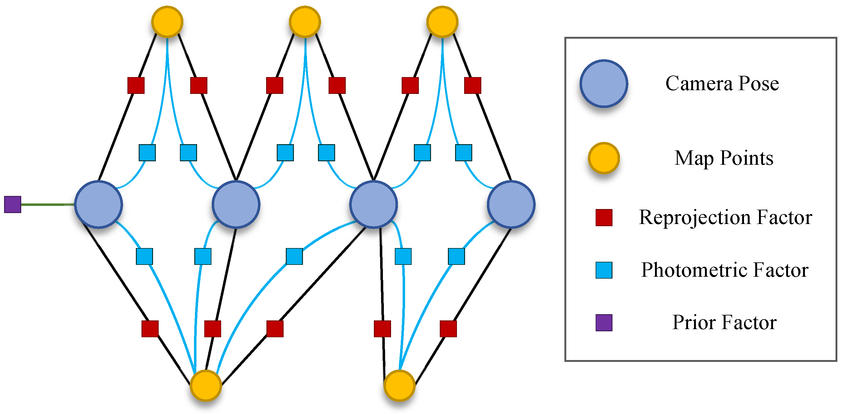
A hybrid visual residual optimization window, which is tightly coupled, is constructed, and the corresponding factor graph relationships are illustrated in Figure 7. The positions of keyframes and map point coordinates within the optimization window are used as nodes, and the reprojection residual, the photometric residual, and the priori residual are used as constraint edges of the nodes.
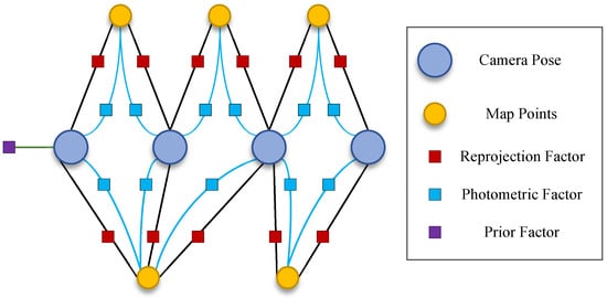
Figure 7.
Factor graph of the proposed hybrid optimization model.
The total cost function is defined as:
where denotes the set of states to be estimated within the optimization window, including the 6 degrees of freedom (DoF) pose of keyframes, the 3D coordinates of map points, and the 1D inverse depth of features. The term denotes the a priori residual, representing the additional constraints of the keyframes and map points that are moved out of the optimization window. The purpose of is to ensure that historical observations still have an impact on the current optimization, thus avoiding drift. is the covariance matrix of the a priori error. and are used to denote the reprojection error and photometric error, respectively, as illustrated in Equations (2) and (5). and L represent all keyframes and map points within the optimization window, respectively. denotes all keyframes where the feature can be seen. The g2o library [39], an open-source optimization toolkit, is employed to solve graph optimization problems.
As previously stated, the geometric reprojection error and the photometric error are tightly coupled within a single cost function, which further improves the localization accuracy and robustness of the system by using only one type of feature to play the role of different residuals.
3.4. Loop Closing Thread
Accurate loop closures have a significant impact on reducing the system’s time-dependent trajectory drift. The feature-based approach enables the front-end to extract ORB features and their descriptors for all frames, facilitating global map reuse. In the loop closing thread, DBoW2 [34] is used to search for loop candidate keyframes. The module in the tracking thread converts the descriptors into vectors using the BoW model. The highest-scoring keyframes are selected as loop candidates by quickly matching these vectors with the keyframe vectors already stored in the database.
Candidate keyframes may contain inconsistencies and need to be verified to avoid incorrect optimization affecting the global map consistency. Therefore, we check the geometric and temporal consistency of the identified candidate keyframes with the image pairs composed of the current keyframe. Initially, the geometric consistency of the candidate keyframe is verified using the co-visibility keyframes of the current keyframe, based on the RANSAC scheme. In the event that a sufficient number of co-visibility keyframes are available to complete the verification process, the candidate frame is successfully verified. Subsequently, the geometric consistency of the candidate keyframe is verified for new keyframes that are temporally consecutive. If multiple consecutive new keyframes are successfully verified, the temporal consistency of the candidate frame is also deemed successful. Subsequent to this, the system attains the ultimate loop closure pair and commences the loop correction.
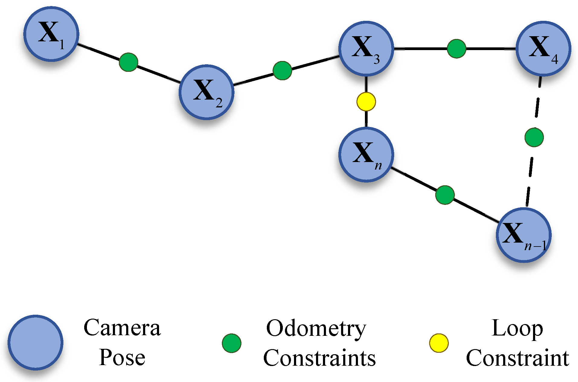
Upon successful detection of the loop closure, the error distributed along the loop is corrected through pose graph optimization. The global pose graph is illustrated in Figure 8, where map points are excluded from the BA process compared to the factor graph, and only the poses are treated as nodes. The method has been shown to significantly reduce the computational complexity of the pose graph. The pose nodes are responsible for representing the state variables that are to be optimized, while the connections between the nodes are responsible for representing the constraints between the individual poses. These constraints include the odometry constraints and the newly formed loop constraint.
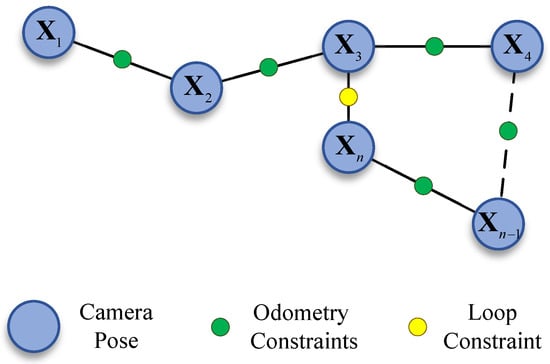
Figure 8.
Global pose graph model for loop correction.
denotes the current node, while represents the loop node it identifies. As illustrated in Figure 8, it is evident that the constraint edges are binary, and the nodes correspond to camera poses. The residuals of a binary edge, using Sim(3) constrained [40] pose graph optimization, are defined as:
where is the relative Sim(3) transformation with the scale factor set to 1, computed between the two keyframes from the SE(3) pose prior to pose graph optimization. The transforms to the tangent space, so the error is a vector belonging to . The total loop closure cost function is defined as:
The pose of the keyframes to be optimized is denoted by . In the algorithm implementation, the first keyframe is fixed, while all other keyframe poses within the map are optimized. denotes the set of edges in the pose graph, and is the covariance matrix of the corresponding edge. The Levenberg–Marquardt algorithm is employed for non-linear optimization. After the optimization of the keyframe pose, the corresponding map points adjust their locations based on the relative relationships before and after optimization.
4. Experiments and Results
In order to validate the effectiveness of the proposed UTH-SLAM system, an extensive evaluation of two publicly available real underwater datasets, AQUALOC [41] and HAUD [42], from different scenarios was collected. Given the superior performance demonstrated by ORB-SLAM3 [20] in recent studies compared to earlier visual SLAM systems, its monocular mode was used as the benchmark. Additionally, to assess the proposed hybrid method, DSO [10] (based on the direct method) and LDSO [27] (based on the hybrid method with loop closing) were also compared. It is important to note that the cameras used in both datasets were not photometrically calibrated; therefore, calibrated camera internal data was employed in these tests.
Since monocular visuals cannot estimate the true scale, we aligned the evaluated trajectory with the ground truth using the Sim(3) transformation in the evo [43] evaluation tool, in accordance with standard practice. Each sequence was executed ten times. The global consistency and local accuracy of the trajectory were then assessed by computing the root mean square error (RMSE) of the absolute trajectory error (ATE) and the relative positional error (RPE), respectively. All experiments were performed on the same laptop, which had an Intel Core i7-9750H CPU at 2.6 GHz and 16 GB of RAM, without utilizing the GPU.
4.1. HAUD Experiments
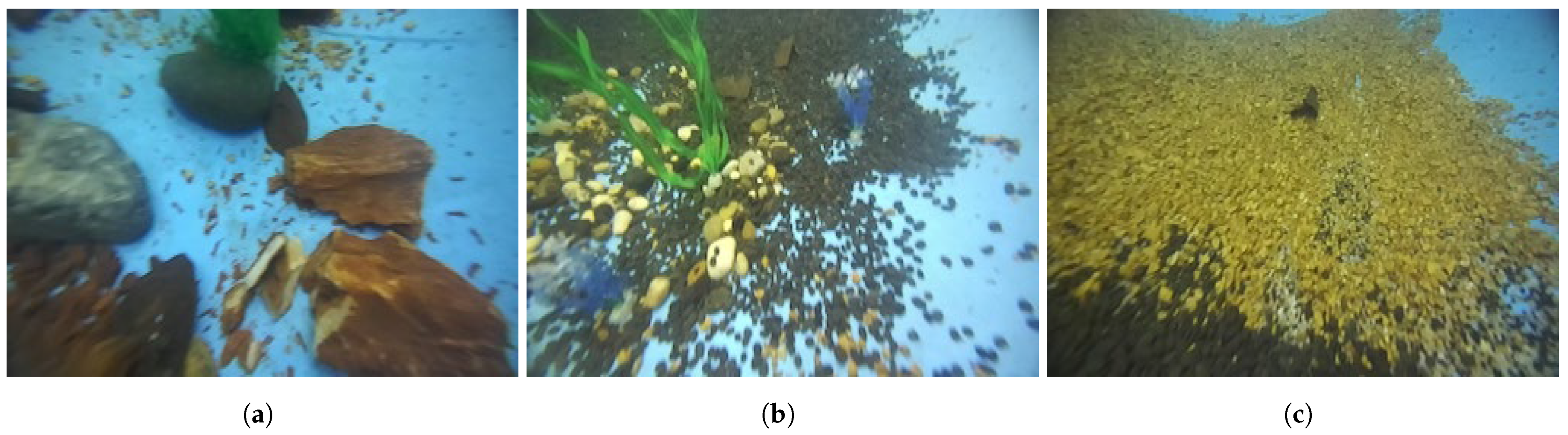
The HUAD dataset was collected in an artificially constructed underwater scene. Rocks, sand, and aquatic plants were placed in the pool, as illustrated in Figure 9. The dataset under scrutiny comprises a total of 10 sequences; the initial 5 sets of sequences for the left images have been selected for evaluation in the present study. These sequences were collected around the whole pool and contain three different regions.
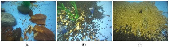
Figure 9.
Images collected from three regions in the HAUD dataset [42]. (a) Rocks. (b) Aquatic plants. (c) Sand.
For systems with a loop closure strategy, results were provided for two versions: one in which the loop closure thread is disabled (w/o LC) and the other in which the loop closure detection function is enabled (w/LC). In some setups, even when the loop closure process was active, the system failed to detect the loop closure.
4.1.1. Global Consistency
The RMSE results for the ATE of the systems tested on the HUAD dataset are presented in Table 1. The following conclusions can be drawn from the quantitative analysis:

Table 1.
Performance comparison results on HAUD (RMSE of ATE in meters).
- 1.
- For systems without a loop closing thread, LDSO and UTH-SLAM demonstrate superior performance in comparison to the other two systems, which are based on a hybrid method. This finding serves to verify the hypothesis that hybrid features or residuals have the capacity to enhance the accuracy of localization by introducing new constraints to the pose estimation in visual scenes of superior quality. Our proposed hybrid approach still outperforms LDSO, obtaining an average ATE reduction of 11.11% compared to it. This is primarily attributable to the fact that the proposed hybrid approach leverages the strengths of both strategies, which are employed not only in the tracking process but also play a pivotal role in the optimization. This leads to enhanced accuracy in keyframe pose estimation within the local map.
- 2.
- For systems with a loop closing thread, ORB-SALM3 and LDSO have been shown to perform comparably. LDSO stores all keyframes along with their associated indirect features and depth estimates in memory for loop closure. However, due to its lack of feature matching for detecting redundant keyframes, it is unable to apply the keyframe culling strategy, leading to relatively large memory consumption. In contrast, ORB-SALM3 has been demonstrated to be more effective in managing redundant keyframes and co-visibility between keyframes. The proposed system leverages this advantage to achieve superior positioning accuracy. UTH-SLAM reduces the Avg. ATE by 20.31% and 22.72% compared to ORB-SALM3 and LDSO, respectively.
- 3.
- All three systems tested with loop closing threads utilized BoW to detect loops. If the loop closure can be effectively detected, the trajectory accuracy is significantly improved after the loop correction. The global localization accuracies of ORB-SALM3, LDSO, and UTH-SLAM are improved by 32.63%, 26.67%, and 36.25%, respectively, after enabling loop closing threads. This also demonstrates how well loop closure works in reducing system drift. The feature-based approach is more convenient than the direct method, as feature descriptors can be used not only for tracking but also for finding the loop closures.
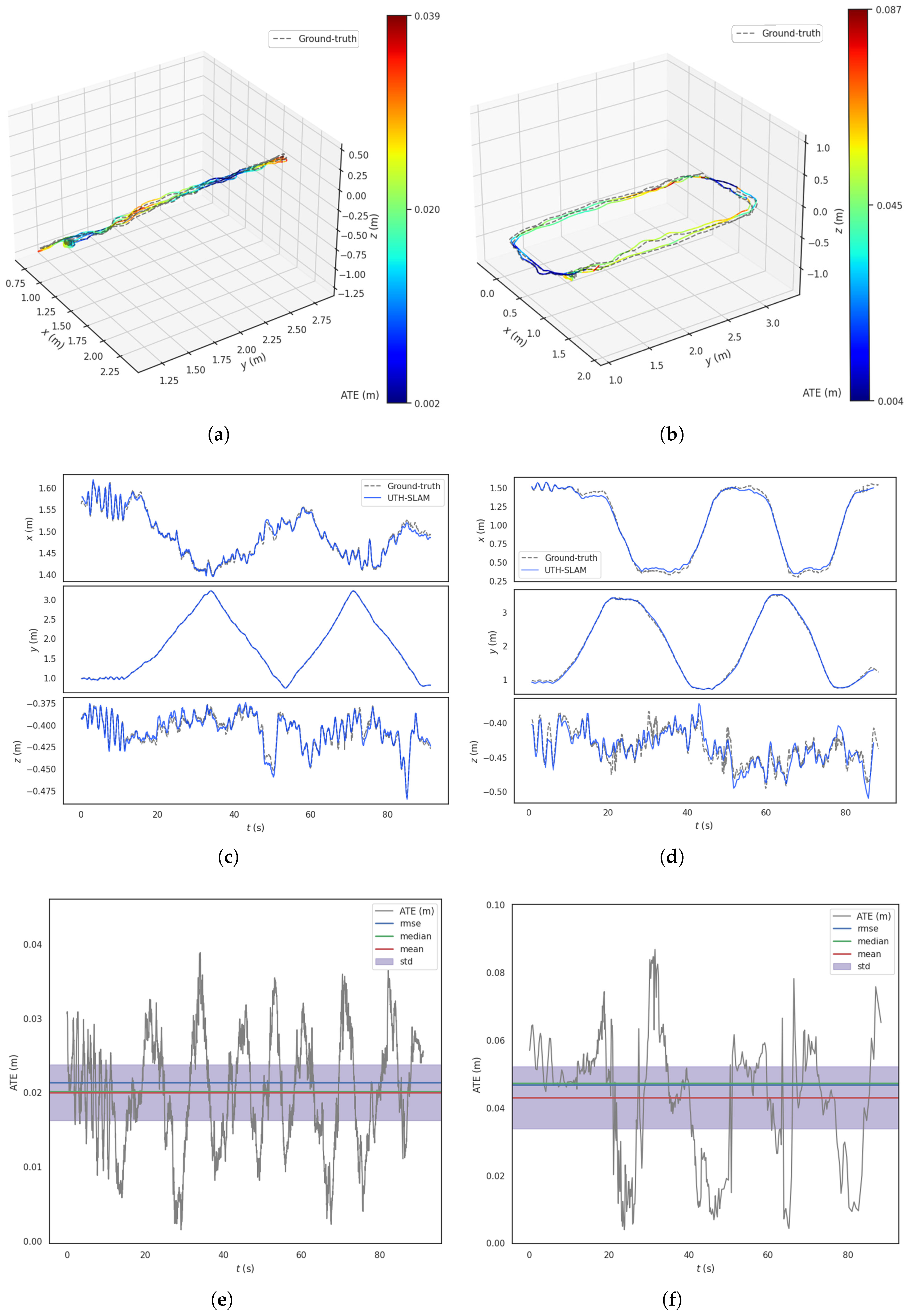
Figure 10 shows the results of UTH-SLAM compared to the ground truth for Seq02 and Seq04 in HAUD. This includes 3D trajectories, x–y–z axis tracking performance, and ATE over time. Qualitatively, the following points can be observed from these figures:
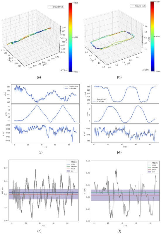
Figure 10.
Results of UTH-SLAM on Seq02 and Seq04 in HAUD. (a) 3D trajectory on Seq02. (b) 3D trajectory on Seq04. (c) The x–y–z axis tracking effect on Seq02. (d) The x–y–z axis tracking effect on Seq04. (e) ATE over time on Seq02. (f) ATE over time on Seq04.
- 1.
- Figure 10a,b show the estimated trajectories made by UTH-SLAM compared to the ground truth. The estimated trajectories are depicted by colored lines, each representing the ATE at that location. In some regions, fluctuations in the error occur due to changes in image texture and motion. As shown in Figure 10c,d, tracking is more accurate along the x–y axes than along the z-axis, especially near the inflection point in the trajectory. The main cause of this is the sudden change in the z-axis movement. In the first step of the proposed hybrid tracking method, the assumption of constant velocity motion for the carrier fails to align with the actual motion at the inflection point, leading to increased error. Overall, UTH-SLAM demonstrates good tracking performance across all three axes.
- 2.
- The ATE exhibits a more uniform fluctuation over time, as shown in Figure 10e,f. The error distributions of the estimated trajectories show no large deviations, and the RMSE, mean, and median values remain closely aligned. This also demonstrates that the proposed system can maintain a relatively stable working state over extended periods, avoiding error accumulation and drastic fluctuations.
4.1.2. Local Accuracy
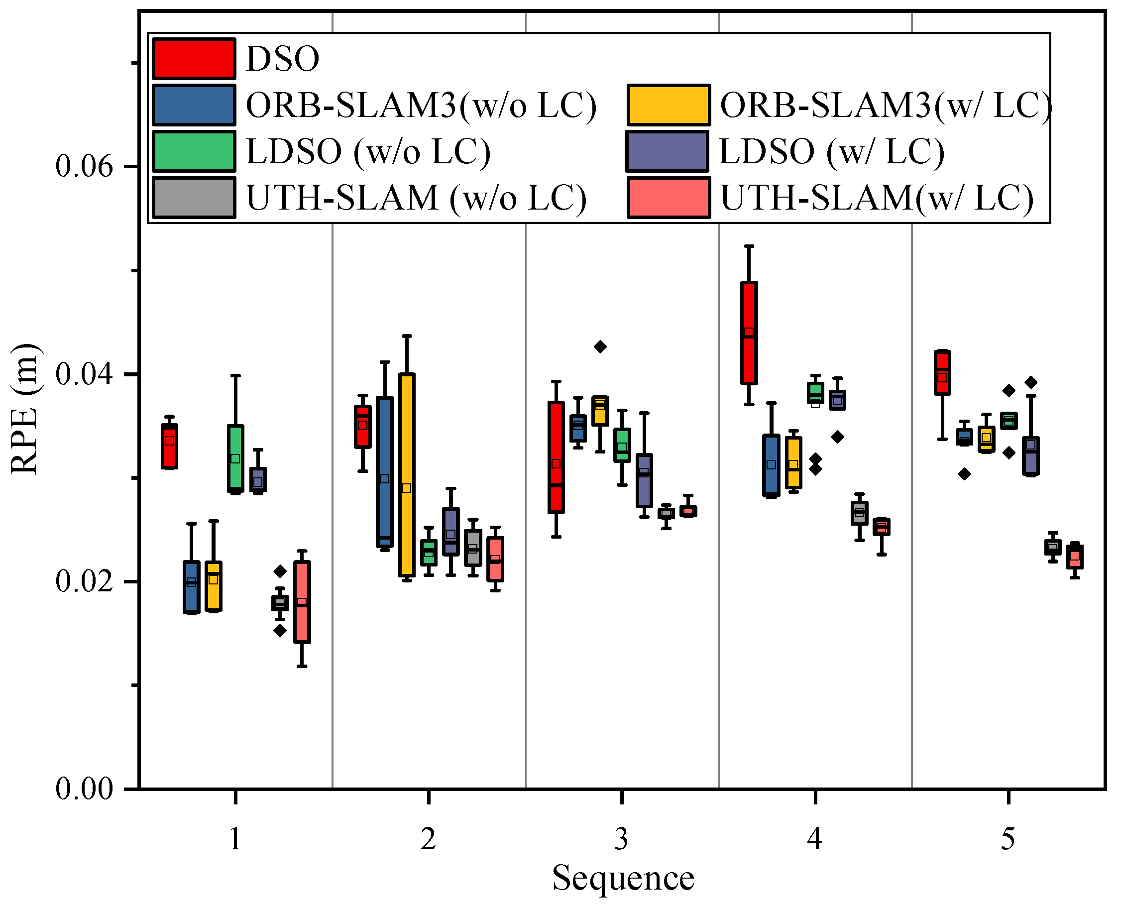
Table 2 presents the RMSE results of RPE with respect to translation for the tested systems. The interval for RPE is set to 0.1 m. Unlike ATE, which reflects the global consistency of the trajectory, RPE measures local motion accuracy by calculating the relative translation between the estimated trajectory and the ground truth over successive frame distances, i.e., the pose error within a segment of the sub-trajectory. Compared to ATE, RPE is less sensitive to the specific time at which the error occurs [44].
Table 2.
Performance comparison results on HAUD (RMSE of RPE in meters).
The results show that UTH-SLAM performs better in terms of local accuracy. Compared to DSO, ORB-SLAM3, and LDSO, our system reduces the Avg. RPE by 37.84%, 23.33%, and 25.81%, respectively. This is mainly because the proposed hybrid tracking strategy refines the poses between adjacent frames, while the tight coupling of two different residuals in local optimization further constrains drift. It is worth noting that when comparing two different versions of the same system, w/o LC and w/ LC, the RPE does not change significantly. Since the RPE only calculates the relative error of a small sub-trajectory, the effect of runtime is significantly reduced. As a result, trajectory drift due to increasing time has a limited effect on the RPE, and the influence of the loop closure thread on it is reduced.
The RPE results from ten trials of the tested systems are shown in box plots in Figure 11. The comparison shows that UTH-SLAM results exhibit good stability and fewer outliers across the trials. This further demonstrates the effectiveness of the proposed hybrid tight coupling strategy in enhancing local accuracy.

Figure 11.
The boxplot of RPE on HAUD.
4.2. AQUALOC Experiments
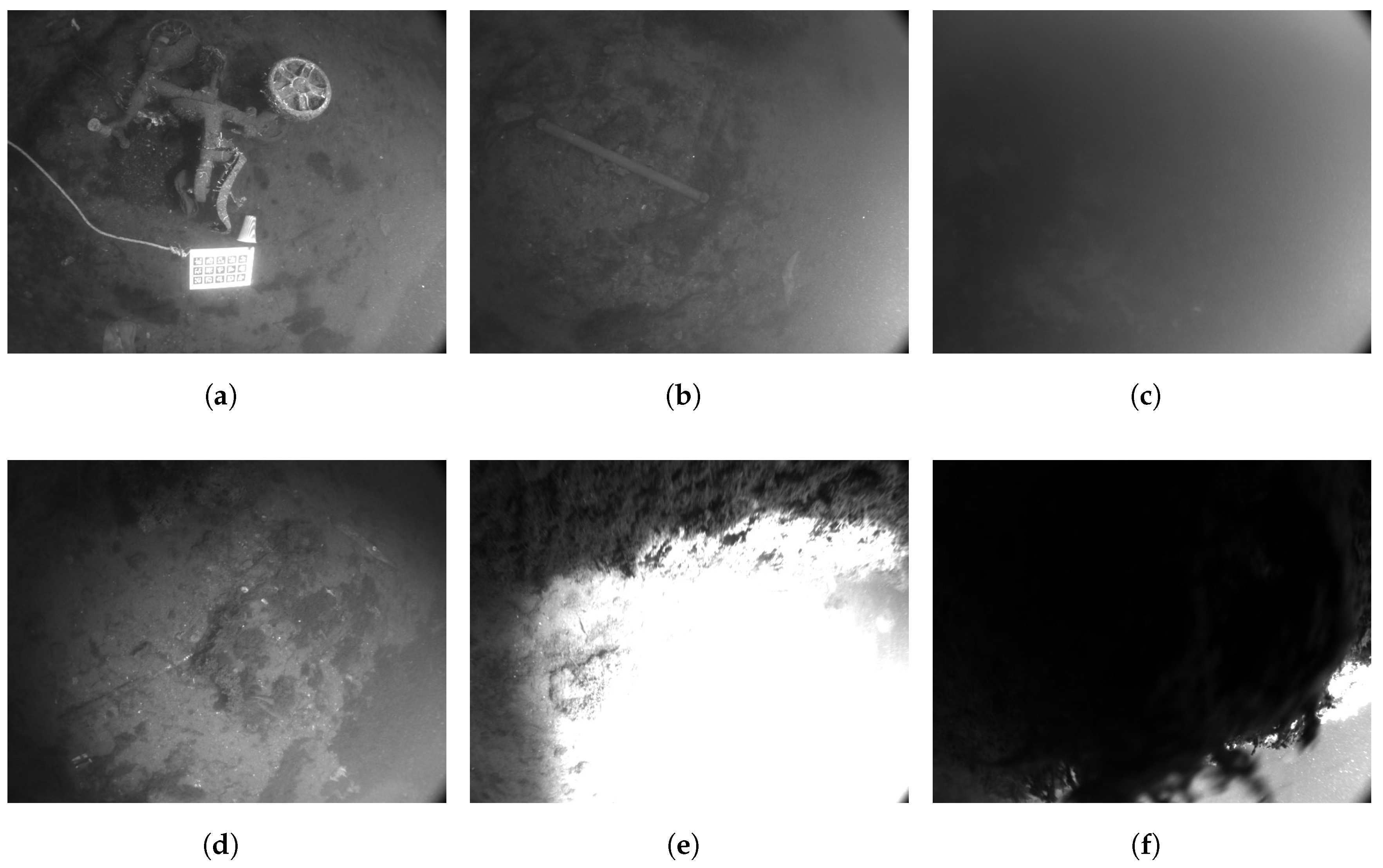
The AQUALOC dataset consists of two sub-sets: harbor and archaeological sites. The completion of the purely visual system was higher on harbor sequences, so this sequence was chosen for testing. The harbor sequences were collected in 3 to 4 m of water. The sun illuminated this shallow environment, but a lighting system was also used in the experiment. In these sequences, images are affected by uneven lighting, backscatter, low texture, and dynamic seagrass, as illustrated in Figure 12a–d. Furthermore, Figure 12e,f illustrate how visual information is rapidly lost due to the collision of the vehicle with surrounding objects. Additionally, the ROV experiences disturbance from waves and cables, resulting in severe movement changes.

Figure 12.
Recording data from the ROV and some image frames in harbor sequences [41]. (a) Uneven lighting. (b) Backscattering. (c) Weak texture. (d) Dynamic seagrass. (e) Exposure. (f) Blocked.
In addition, most trials involved only a few loops, precluding an analysis of loop closure in this dataset. Consequently, experiments were conducted using the original systems. In contrast to the HUAD dataset, the harbor sequences were collected from real natural underwater environments, which posed a greater challenge to the system.
4.2.1. Quantitative Analysis
The RMSE of ATE results for six sequences in the harbor sequences are shown in Table 3. It should be noted that the dataset contains a total of seven sequences; however, when testing the systems on the fourth and seventh sequences, all systems failed to complete the task. Consequently, these results have not been included in the report. This failure was primarily due to ROV collisions with objects, which caused occlusion of the field of view and exposure to the illumination system, as illustrated in Figure 12e,f. This situation has catastrophic consequences for systems relying solely on vision for localization. By analyzing the quantitative results in Table 3, we can obtain the following conclusions.
Table 3.
Performance comparison results on harbor sequences (RMSE of ATE in meters).
- 1.
- In natural underwater scenes, the effect of light variations becomes more pronounced, and both DSO and LDSO perform poorly. The tracking approach, which assumes photometric invariance, results in poor pose estimation between adjacent frames, which negatively affects the localization results. Furthermore, in Seq01, the ROV experiences large-scale motion, which poses a challenge for the direct method tracking approach. The DSO and LDSO were shown to produce drastic drifts, bringing the ATE to 0.933 m and 0.709 m, respectively, while the result obtained in this study is only 0.129 m. The proposed hybrid tracking strategy uses a feature-based method to estimate the rough pose, followed by direct refinement and a new projection of it. This approach is not only more robust to large geometric distortions but also enhances estimation accuracy. The effectiveness of the proposed approach is evident in the substantial reduction in Avg. ATE, with UTH-SLAM achieving a 76% and 71.6% reduction compared to DSO and LDSO, respectively.
- 2.
- In the context of harbor sequences, ORB-SLAM3 has been shown to outperform its counterparts, DSO and LDSO, due to its enhanced underwater camera internal parameter calibration and advanced processing algorithms. However, the performance of feature-based tracking is unstable in low-texture sequences, as illustrated in Figure 12c. The proposed system has been demonstrated to improve location accuracy by 47.25% compared to ORB-SLAM3. This improvement can be attributed to the hybrid approach we employ, which fully leverages both the feature-based and direct methods by refining the pose at the front-end and tightly coupling the two residuals at the optimization stage. This enables UTH-SLAM to generate more precise keyframe pose estimates.
The proposed hybrid tracking method is further validated by the results of experiments. As shown in Figure 13, the number of features tracked over time for ORB-SLAM3 and UTH-SLAM on Seq02 is presented. Results from five experiments are shown for each system. It is evident that the system rapidly matches a substantial number of features through pairwise polar geometry within the first ten seconds, completing the initialization process and resulting in a significantly higher number of features being tracked. ORB-SLAM3 employs the constant velocity model for rough pose estimation. The proposed hybrid strategy refines the rough estimation by using the direct method along with a new projection. As shown in the figure, the number of tracked features is significantly increased, thereby enhancing the system’s tracking stability. A comparative analysis reveals that the number of features tracked by UTH-SLAM increases by 31.41% on average compared to ORB-SLAM3.
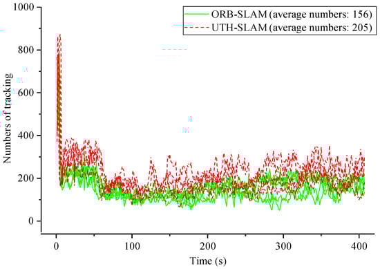
Figure 13.
Comparison of the number of features tracked over time between ORB-SLAM3 and UTH-SLAM on Seq02.
Furthermore, a comparison was made of the time costs of the ORB-SLAM3 and UTH-SLAM systems when processing each frame, as demonstrated in Table 4. It was observed that the time required for the tracking thread increased significantly. This was primarily due to the proposed hybrid tracking strategy, which imposed further constraints on the tracking pose, thereby increasing the computational load. The judicious selection of robust feature points led to a marginal alteration in the number of residuals in the local optimization, thereby ensuring that the computational cost of the local mapping thread remained relatively unchanged. UTH-SLAM and ORB-SLAM3 utilize the same loop closing thread, thus resulting in analogous consumption patterns. It is evident that the parallelization of these three threads is instrumental in ensuring the real-time capability of the proposed method, despite its concomitant increase in consumption.
Table 4.
The computation time cost of ORB-SLAM3 and UTH-SLAM (ms/frame).
The memory and CPU power consumption of all tested systems was recorded on the laptop used, as shown in Table 5. It is evident that DSO exhibited the most minimal memory consumption, a consequence of its accelerated tracking strategy. The LDSO augmented the memory usage by incorporating closed-loop threads, feature extraction, and descriptor calculation. In comparison with ORB-SLAM3, the proposed hybrid strategy also resulted in increased memory consumption. A comprehensive evaluation of the data reveals that there is no statistically significant difference in CPU power consumption among the systems that have been tested. Subsequent testing of the UTH-SLAM system on an onboard computer will be conducted in order to validate its performance.
Table 5.
Comparison of memory and power consumption of the tested system.
4.2.2. Qualitative Analysis
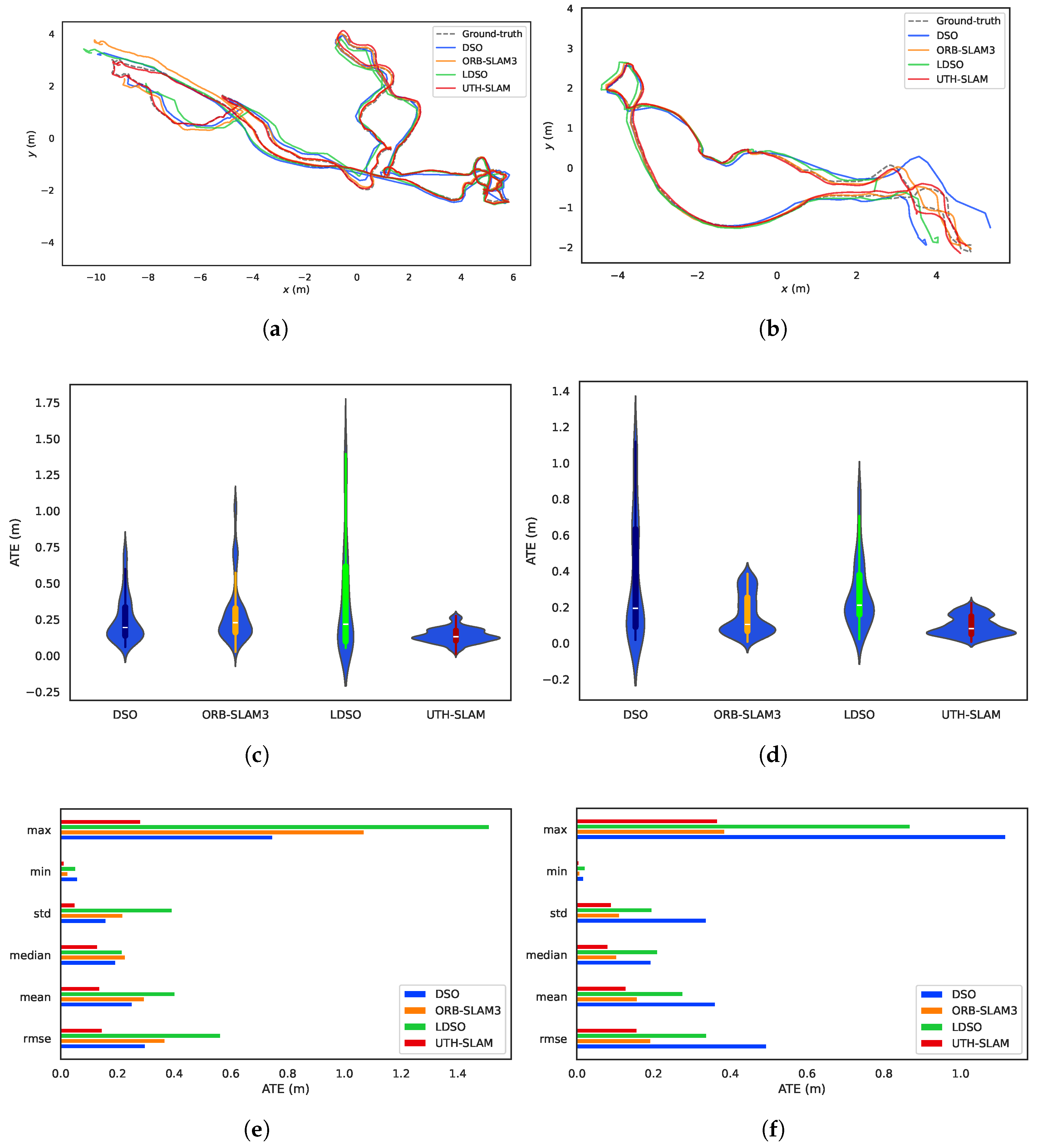
The operation of these systems is shown in Figure 14. The proposed system is shown in Figure 14d. In the lower left image frame, the green point represents the selected robust feature, which was used to construct the hybrid visual residuals. As shown in Figure 15, a comparative analysis was performed on Seq02 and Seq05 from several perspectives, including trajectory tracking along the x-y axis, the violin plots of the ATE, and individual ATE statistics. The following conclusions can be drawn from these figures:
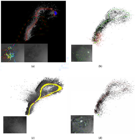
Figure 14.
Demonstration of the running window of the test systems on Seq01 of harbor sequences. (a) DSO. (b) ORB-SLAM3. (c) LDSO. (d) UTH-SLAM.
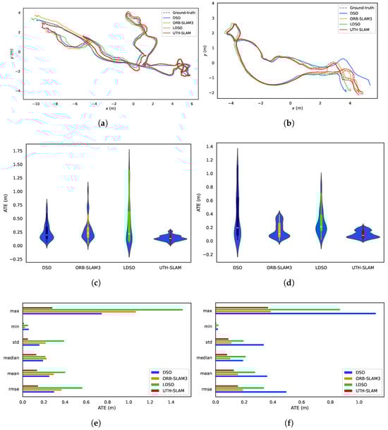
Figure 15.
The tested systems were compared on Seq02 and Seq05 of harbor sequences. (a) Trajectories on Seq02. (b) Trajectories on Seq05. (c) Violin plot of ATE on Seq02. (d) Violin plot of ATE on Seq05. (e) Various statistics of ATE on Seq02. (f) Various statistics of ATE on Seq05.
- 1.
- As shown in Figure 14a,c, both DSO and LDSO use a large number of pixel features to generate denser maps with better visibility compared to sparse maps. LDSO also uses corners as direct features and contributes photometric residuals. These corners are extracted using ORB descriptors, enabling loop closure detection. The system also constructs sparse maps, as shown in Figure 14d. The key distinction is that UTH-SLAM integrates geometric and photometric residuals more robustly by using stable features, providing stronger constraints for pose estimation and mapping.
- 2.
- The trajectories assessed by DSO, ORB-SLAM3, and LDSO showed significant pose errors, especially in the initial phase, as shown in Figure 15a,b. In contrast, UTH-SLAM demonstrated precise tracking throughout the entire trajectory. This superior performance can be primarily attributed to the efficacy of the proposed hybrid tracking strategy, which refines the pose estimation from the initial phase of the trajectory and reduces the instability of the system.
- 3.
- As shown by the violin plots in Figure 15c,d, the proposed system estimates trajectories with a higher concentration of ATE and fewer outliers. The hybrid strategy discussed here has been shown to exhibit greater stability and robustness than other methods. The maximum, minimum, standard deviation, median, and mean values of the ATE obtained by UTH-SLAM all show a similar trend to the RMSE of ATE across two sequences, as shown in Figure 15e,f. This finding underscores the consistent and reliable performance characteristics of our system.
4.3. Discussion
As shown in Table 1 and Table 3, a comparison of these systems shows that the tested ones perform better in artificially generated scenarios. Natural underwater environments, characterized by uneven lighting, lack of texture, and water current interference, present greater challenges for these visual localization systems.
Furthermore, in certain extreme cases, as illustrated in Figure 12e,f, when the camera is obstructed or severely overexposed, there is a paucity of visual features, resulting in inaccurate pose estimates. All systems that were subjected to rigorous testing were found to be incapable of accurately tracking images during the specified period. This ultimately resulted in the failure of the system. Consequently, the use of a solitary visual sensor within the context of a harsh underwater environment is not advised. In certain limited cases, the fusion of the camera with other heterogeneous sensors can offer significant advantages.
Photometric calibration has not been performed on either of these two open-source datasets. For DSO and LDSO, which directly utilize photometric information, they can run using only the camera’s internal calibration results. Nevertheless, they may perform better with photometric calibration. A comparison of the HAUD and harbor datasets reveals that the HAUD dataset provides sufficient and uniform lighting during recording, enabling DSO and LDSO to perform better. However, in natural underwater environments, the lighting is intricate, and photometric calibration becomes challenging. The UTH-SLAM system was developed to address these challenges by leveraging the strengths of the direct method, which is based on feature-based techniques. The efficacy of the system is demonstrated by its favorable performance on both datasets.
5. Conclusions
In this paper, a tightly coupled hybrid monocular SLAM system, named UTH-SLAM, designed for underwater environments, is proposed. This system is characterized by the integration of both feature-based and direct methods. The direct strategy is utilized to refine the inter-frame estimates obtained by feature matching. Direct sparse optical flow is used to handle tracking failures. Furthermore, robust features are employed to tightly couple the photometric residual and geometric reprojection residual in the local optimization model concurrently. From the comparative experiments, the following conclusions are drawn:
- 1.
- In comparison with ORB-SLAM3, which uses the feature-based method, and DSO, which uses the direct method, the proposed tightly coupled hybrid system utilizes the distinct strategies to their fullest potential. The efficacy of both global consistency and local accuracy is demonstrated in underwater scenario tests.
- 2.
- The employment of a hybrid tracking strategy has been shown to further improve the reliability of pose estimation between adjacent frames and the stability of tracking. A comparison of UTH-SLAM with ORB-SLAM3 reveals a 31.41% increase in the number of feature tracks. This enhancement in adaptability is particularly significant in low-texture underwater environments, where it can substantially impact system performance.
- 3.
- The proposed tightly coupled optimization strategy has demonstrated the ability to accomplish two different residual constraints using a single type of feature. The experimental findings demonstrate the superior localization accuracy of the proposed method. In the challenging natural underwater environment, UTH-SLAM reduces the ATE by 76%, 47.25%, and 71.6% compared to DSO, ORB-SLAM3, and LDSO, respectively.
The visual localization system described in this paper shows good performance in both artificial pools and natural underwater environments. The experimental findings demonstrate that employing a single vision camera is inadequate to address the intricate challenges posed by field-of-view occlusion. Subsequent research endeavors will concentrate on multi-sensor fusion technology, which integrates vision with IMU and DVL to enhance the robustness and stability of underwater localization.
Author Contributions
Conceptualization, T.Z. and D.J.; methodology, S.D.; software, S.D. and X.Y.; validation, Y.L. (Yanze Lu) and Y.L. (Yu Lu); investigation, X.Q. and Y.L. (Yanze Lu); data curation, S.D.; writing—original draft preparation, S.D.; writing—review and editing, T.Z. and D.J.; visualization, T.Z.; supervision, T.Z. and X.Y.; funding acquisition, T.Z., D.J. and X.Y. All authors have read and agreed to the published version of the manuscript.
Funding
This research was funded in part by the Southern Marine Science and Engineering Guangdong Laboratory (Zhuhai) under Grant No. SML2023SP228; in part by the National Key Research and Development Program of China under Grant No. 2024YFB4710803 and Grant No. 2024YFB4710805; in part by the National Natural Science Foundation of China under Grant No. U22A2012; in part by the Guangdong Basic and Applied Basic Research Foundation under Grant No. 2023A1515012039; in part by the Fundamental Research Funds for the Central Universities, Sun Yat-sen University under Grant No. 23ptpy101 and Grant No. 23xkjc012; in part by the Open Fund for Laboratory of Science and Technology on Marine Navigation and Control, China State Shipbuilding Corporation under Grant No. 2024010301; and in part by the Open Fund Project of Technology Innovation Center for South China Sea Remote Sensing, Surveying and Mapping Collaborative Application, Ministry of Natural Resources, P.R. China under Grant No. RSSMCA-2024-B016.
Data Availability Statement
The original contributions presented in the study are included in the article; further inquiries can be directed to the corresponding author.
Acknowledgments
We gratefully acknowledge the HUAD dataset from Shanghai Jiao Tong University: https://bat.sjtu.edu.cn/zh/haud-dataset/ (accessed on 3 January 2024); and the AQUALOC dataset from Université Paris Saclay: https://www.lirmm.fr/aqualoc/ (accessed on 18 March 2023). These publicly available resources contributed to the results reported in this paper.
Conflicts of Interest
Yu Lu was employed by China Merchants Marine Equipment Research Institute Co., Ltd. The remaining authors declare that the research was conducted in the absence of any commercial or financial relationships that could be construed as a potential conflict of interest.
References
- Moud, H.I.; Shojaei, A.; Flood, I. Current and future applications of unmanned surface, underwater, and ground vehicles in construction. In Proceedings of the Construction Research Congress 2018, New Orleans, LA, USA, 2–4 April 2018; pp. 106–115. [Google Scholar]
- Ditria, E.M.; Buelow, C.A.; Gonzalez-Rivero, M.; Connolly, R.M. Artificial intelligence and automated monitoring for assisting conservation of marine ecosystems: A perspective. Front. Mar. Sci. 2022, 9, 918104. [Google Scholar] [CrossRef]
- Martin, S. An Introduction to Ocean Remote Sensing; Cambridge University Press: Cambridge, UK, 2014. [Google Scholar]
- Zhang, B.; Ji, D.; Liu, S.; Zhu, X.; Xu, W. Autonomous underwater vehicle navigation: A review. Ocean Eng. 2023, 273, 113861. [Google Scholar] [CrossRef]
- Ding, S.; Zhang, T.; Lei, M.; Chai, H.; Jia, F. Robust visual-based localization and mapping for underwater vehicles: A survey. Ocean Eng. 2024, 312, 119274. [Google Scholar] [CrossRef]
- Wang, X.; Fan, X.; Shi, P.; Ni, J.; Zhou, Z. An overview of key SLAM technologies for underwater scenes. Remote Sens. 2023, 15, 2496. [Google Scholar] [CrossRef]
- Dou, H.; Zhao, X.; Liu, B.; Jia, Y.; Wang, G.; Wang, C. Enhancing Real-Time Visual SLAM with Distant Landmarks in Large-Scale Environments. Drones 2024, 8, 586. [Google Scholar] [CrossRef]
- Li, D.; Zhang, F.; Feng, J.; Wang, Z.; Fan, J.; Li, Y.; Li, J.; Yang, T. Ld-slam: A robust and accurate gnss-aided multi-map method for long-distance visual slam. Remote Sens. 2023, 15, 4442. [Google Scholar] [CrossRef]
- Wang, Z.; Li, X.; Chen, P.; Luo, D.; Zheng, G.; Chen, X. A Monocular Ranging Method for Ship Targets Based on Unmanned Surface Vessels in a Shaking Environment. Remote Sens. 2024, 16, 220. [Google Scholar] [CrossRef]
- Engel, J.; Koltun, V.; Cremers, D. Direct sparse odometry. IEEE Trans. Pattern Anal. Mach. Intell. 2017, 40, 611–625. [Google Scholar] [CrossRef]
- Zhou, L.; Wang, S.; Kaess, M. DPLVO: Direct point-line monocular visual odometry. IEEE Robot. Autom. Lett. 2021, 6, 7113–7120. [Google Scholar] [CrossRef]
- Lowe, D.G. Distinctive image features from scale-invariant keypoints. Int. J. Comput. Vis. 2004, 60, 91–110. [Google Scholar] [CrossRef]
- Meireles, M.; Lourenço, R.; Dias, A.; Almeida, J.M.; Silva, H.; Martins, A. Real time visual SLAM for underwater robotic inspection. In Proceedings of the 2014 Oceans, St. John’s, NL, Canada, 14–19 September 2014; pp. 1–5. [Google Scholar]
- Bay, H.; Tuytelaars, T.; Van Gool, L. SURF: Speeded up robust features. In Computer Vision—ECCV 2006: 9th European Conference on Computer Vision, Graz, Austria, 7–13 May 2006, Proceedings, Part I; Springer: Berlin/Heidelberg, Germany, 2006; pp. 404–417. [Google Scholar]
- Aulinas, J.; Petillot, Y.R.; Lladó, X.; Salvi, J.; Garcia, R. Vision-based underwater SLAM for the SPARUS AUV. In Proceedings of the 10th International Conference on Computer and IT Applications in the Maritime Industries, Berlin, Germany, 2–4 May 2011; pp. 171–179. [Google Scholar]
- Salvi, J.; Petillo, Y.; Thomas, S.; Aulinas, J. Visual slam for underwater vehicles using video velocity log and natural landmarks. In Proceedings of the OCEANS 2008, Quebec City, QC, Canada, 15–18 September 2008; pp. 1–6. [Google Scholar]
- Rublee, E.; Rabaud, V.; Konolige, K.; Bradski, G. ORB: An efficient alternative to SIFT or SURF. In Proceedings of the 2011 International Conference on Computer Vision, Barcelona, Spain, 6–13 November 2011; pp. 2564–2571. [Google Scholar]
- Mur-Artal, R.; Montiel, J.M.M.; Tardos, J.D. ORB-SLAM: A versatile and accurate monocular SLAM system. IEEE Trans. Robot. 2015, 31, 1147–1163. [Google Scholar] [CrossRef]
- Mur-Artal, R.; Tardós, J.D. Orb-slam2: An open-source slam system for monocular, stereo, and rgb-d cameras. IEEE Trans. Robot. 2017, 33, 1255–1262. [Google Scholar] [CrossRef]
- Campos, C.; Elvira, R.; Rodríguez, J.J.G.; Montiel, J.M.; Tardós, J.D. Orb-slam3: An accurate open-source library for visual, visual-inertial, and multimap slam. IEEE Trans. Robot. 2021, 37, 1874–1890. [Google Scholar] [CrossRef]
- Rosten, E.; Drummond, T. Machine learning for high-speed corner detection. In Computer Vision—ECCV 2006: 9th European Conference on Computer Vision, Graz, Austria, 7–13 May 2006, Proceedings, Part I; Springer: Berlin/Heidelberg, Germany, 2006; pp. 430–443. [Google Scholar]
- Calonder, M.; Lepetit, V.; Strecha, C.; Fua, P. BRIEF: Binary robust independent elementary features. In Computer Vision—ECCV 2010: 11th European Conference on Computer Vision, Heraklion, Greece, 5–11 September 2010, Proceedings, Part IV; Springer: Berlin/Heidelberg, Germany, 2010; pp. 778–792. [Google Scholar]
- Xu, S.; Ma, T.; Li, Y.; Ding, S.; Gao, J.; Xia, J.; Qi, H.; Gu, H. An effective stereo SLAM with high-level primitives in underwater environment. Meas. Sci. Technol. 2023, 34, 105405. [Google Scholar] [CrossRef]
- Li, J.; Sun, C.; Hu, Y.; Yu, H. An underwater stereo matching method based on ORB features. Optoelectron. Eng. 2019, 46, 180456. [Google Scholar]
- Xia, J.; Ma, T.; Li, Y.; Xu, S.; Qi, H. A scale-aware monocular odometry for fishnet inspection with both repeated and weak features. IEEE Trans. Instrum. Meas. 2023, 73, 1–11. [Google Scholar] [CrossRef]
- Forster, C.; Pizzoli, M.; Scaramuzza, D. SVO: Fast semi-direct monocular visual odometry. In Proceedings of the 2014 IEEE International Conference on Robotics and Automation (ICRA), Hong Kong, China, 31 May–7 June 2014; pp. 15–22. [Google Scholar]
- Gao, X.; Wang, R.; Demmel, N.; Cremers, D. LDSO: Direct sparse odometry with loop closure. In Proceedings of the 2018 IEEE/RSJ International Conference on Intelligent Robots and Systems (IROS), Madrid, Spain, 1–5 October 2018; pp. 2198–2204. [Google Scholar]
- Yu, Q.; Xiao, J.; Lu, H.; Zheng, Z. Hybrid-residual-based RGBD visual odometry. IEEE Access 2018, 6, 28540–28551. [Google Scholar] [CrossRef]
- Lee, S.H.; Civera, J. Loosely-coupled semi-direct monocular slam. IEEE Robot. Autom. Lett. 2018, 4, 399–406. [Google Scholar] [CrossRef]
- Younes, G.; Asmar, D.; Zelek, J. FDMO: Feature assisted direct monocular odometry. arXiv 2018, arXiv:1804.05422. [Google Scholar]
- Younes, G.; Asmar, D.; Zelek, J. A unified formulation for visual odometry. In Proceedings of the 2019 IEEE/RSJ International Conference on Intelligent Robots and Systems (IROS), Macau, China, 3–8 November 2019; pp. 6237–6244. [Google Scholar]
- Ding, S.; Zhang, T.; Li, Y.; Xu, S.; Lei, M. Underwater multi-sensor fusion localization with visual-inertial-depth using hybrid residuals and efficient loop closing. Measurement 2024, 238, 115245. [Google Scholar] [CrossRef]
- Miao, R.; Qian, J.; Song, Y.; Ying, R.; Liu, P. UniVIO: Unified direct and feature-based underwater stereo visual-inertial odometry. IEEE Trans. Instrum. Meas. 2021, 71, 1–14. [Google Scholar] [CrossRef]
- Gálvez-López, D.; Tardos, J.D. Bags of binary words for fast place recognition in image sequences. IEEE Trans. Robot. 2012, 28, 1188–1197. [Google Scholar] [CrossRef]
- Leutenegger, S.; Lynen, S.; Bosse, M.; Siegwart, R.; Furgale, P. Keyframe-based visual-inertial odometry using nonlinear optimization. Int. J. Robot. Res. 2015, 34, 314–334. [Google Scholar] [CrossRef]
- Lucas, B.D.; Kanade, T. An iterative image registration technique with an application to stereo vision. In Proceedings of the IJCAI’81: 7th International Joint Conference on ARTIFICIAL Intelligence, Vancouver, BC, Canada, 24–28 August 1981; Volume 2, pp. 674–679. [Google Scholar]
- Fischler, M.A.; Bolles, R.C. Random sample consensus: A paradigm for model fitting with applications to image analysis and automated cartography. Commun. ACM 1981, 24, 381–395. [Google Scholar] [CrossRef]
- Urban, S.; Leitloff, J.; Hinz, S. Mlpnp-a real-time maximum likelihood solution to the perspective-n-point problem. arXiv 2016, arXiv:1607.08112. [Google Scholar]
- Kümmerle, R.; Grisetti, G.; Strasdat, H.; Konolige, K.; Burgard, W. G2o: A general framework for graph optimization. In Proceedings of the 2011 IEEE International Conference on Robotics and Automation, Shanghai, China, 9–13 May 2011; pp. 3607–3613. [Google Scholar]
- Strasdat, H.; Montiel, J.; Davison, A.J. Scale drift-aware large scale monocular SLAM. Robot. Sci. Syst. VI 2010, 2, 7. [Google Scholar]
- Ferrera, M.; Creuze, V.; Moras, J.; Trouvé-Peloux, P. AQUALOC: An underwater dataset for visual-inertial-pressure localization. Int. J. Robot. Res. 2019, 38, 1549–1559. [Google Scholar] [CrossRef]
- Song, Y.; Qian, J.; Miao, R.; Xue, W.; Ying, R.; Liu, P. HAUD: A high-accuracy underwater dataset for visual-inertial odometry. In Proceedings of the 2021 IEEE Sensors, Virtual, 31 October–3 November 2021; pp. 1–4. [Google Scholar]
- Michael, G. evo: Python Package for the Evaluation of Odometry and Slam. Available online: https://github.com/MichaelGrupp/evo (accessed on 2 March 2025).
- Zhang, Z.; Scaramuzza, D. A tutorial on quantitative trajectory evaluation for visual (-inertial) odometry. In Proceedings of the 2018 IEEE/RSJ International Conference on Intelligent Robots and Systems (IROS), Madrid, Spain, 1–5 October 2018; pp. 7244–7251. [Google Scholar]


Disclaimer/Publisher’s Note: The statements, opinions and data contained in all publications are solely those of the individual author(s) and contributor(s) and not of MDPI and/or the editor(s). MDPI and/or the editor(s) disclaim responsibility for any injury to people or property resulting from any ideas, methods, instructions or products referred to in the content. |
© 2025 by the authors. Licensee MDPI, Basel, Switzerland. This article is an open access article distributed under the terms and conditions of the Creative Commons Attribution (CC BY) license (https://creativecommons.org/licenses/by/4.0/).