Article

Numerical Analysis of Hydrodynamic Interactions Based on Ship Types

1
Division of Navigation Convergence Studies, Korea Maritime and Ocean University, Busan 49112, Republic of Korea
2
Training Ship, Pukyong National University, Busan 48513, Republic of Korea
*
Author to whom correspondence should be addressed.
J. Mar. Sci. Eng. 2025, 13(6), 1075; https://doi.org/10.3390/jmse13061075
Submission received: 22 April 2025 / Revised: 21 May 2025 / Accepted: 27 May 2025 / Published: 29 May 2025
(This article belongs to the Special Issue Models and Simulations of Ship Manoeuvring)

Abstract

:
To ensure safe navigation, ship operators must not only meet the criteria defined in the International Maritime Organization (IMO) maneuverability standards but also understand maneuvering characteristics in restricted waters. This study numerically analyzed the hydrodynamic lateral forces and yaw moments acting on a stern trawler, a container ship, and a very large crude carrier (VLCC) with different hull forms as they navigated near a semi-circular bank wall. The effects of varying bank radius, lateral clearance, and water depth were examined. The results showed that the VLCC experienced the strongest attractive lateral force, while the stern trawler exhibited the most significant yaw moment. The hydrodynamic interaction patterns of the stern trawler and container ship were similar, whereas the VLCC displayed distinct behavior due to its fuller hull and greater inertia. These findings demonstrate that hull geometry significantly influences hydrodynamic interactions near boundaries, and the degree of response varies by ship type. The results provide valuable reference data for improving navigation safety in confined waters and preventing marine accidents such as collisions and groundings. This study contributes to a better understanding of ship–bank interaction and offers a theoretical basis for maneuvering assessments of various ship types in restricted maritime environments.

1. Introduction

The maneuvering characteristics of ships in restricted waters, such as shallow and narrow regions like straits or harbors, significantly differ from those in deep and open waters. In particular, the hydrodynamic interactions generated when a ship navigates near another vessel or the bank walls of various shapes, such as breakwaters, can lead to sudden changes in the maneuvering motion of the ship.
However, the maneuvering booklet available on a ship’s bridge primarily focuses on information related to the IMO maneuverability standards [1] and lacks detailed descriptions of the maneuvering characteristics in restricted waters.
The maneuvering characteristics of ships in restricted waters can vary significantly depending on the ship type. This can occasionally place ship operators in challenging situations, often leading to marine accidents. In particular, pilots tasked with navigating various types of ships in restricted waters frequently face difficulties owing to the inherent maneuvering characteristics of each ship.
Recently, the container ship Ever Given, which is 400 m long and has a gross tonnage of 220,900 t, ran aground while transiting the Suez Canal [2]. Although the accident resulted from a combination of factors, including the wind, Baric et al. suggested that the bank effect likely played a significant role [3].
The changes in the maneuvering characteristics of a ship caused by hydrodynamic effects when navigating close to another ship or near a bank wall can be attributed to two primary factors: the first is the interaction effect, which is influenced by the hull form (ship type), shape of obstacles, and proximity between the ship and the obstacles; and the second is the shallow water effect, which is primarily determined by the ratio of the water depth to the ship draft (hereafter referred to as H / d ).
Analyzing the impact of hydrodynamic effects caused by various factors on the maneuvering characteristics of a ship is crucial for preventing maritime accidents. However, conducting experimental studies using full-scale poses significant challenges and risks, and research involving model tests is time-consuming and expensive. Consequently, estimation studies that use numerical calculations play a vital role in this field.
Various studies have been continuously conducted to analyze ship maneuverability, particularly focusing on bank effects, shallow water effects, and ship-propeller interactions. These studies have proposed diverse numerical and experimental models for predicting maneuvering motion under complex hydrodynamic conditions.

1.1. Ship-Bank Interaction and Bank Effect

Recent studies have shown significant progress in understanding ship–bank interaction through both numerical and experimental approaches.
Zou and Zou (2022) conducted a comparative URANS-based analysis of crabbing motion near quay walls, emphasizing the importance of accurate turbulence modeling and time-step control in predicting lateral hydrodynamic performance [4]. Delefortrie et al. (2024) developed a 6 DOF experimental formulation using towing tank tests to assess maneuvering performance near banks, incorporating lateral force locations and vertical motions such as heel, trim, and sinkage [5].
These findings extend earlier foundational work. For example, Ma et al. (2013) investigated bank-induced asymmetrical forces on ships using numerical simulations, accounting for rudder and wake effects [6]. Lee and Kang (2004) also provided experimental data on ship–bank wall interactions in confined waters [7]. These contributions confirm the critical influence of lateral and yaw moments when operating in proximity to banks.
Yasukawa (2019) examined course stability for a car carrier near a sloped bank through captive model tests and confirmed the stabilizing role of autopilot control under otherwise unstable conditions [8]. Such modern studies reflect the shift from earlier theoretical models (e.g., Kijima et al. [9,10,11]) to validate computational and empirical methods.

1.2. Shallow Water Effects

Shallow water flow dynamics have been widely studied using high-fidelity CFD approaches.
Martić et al. (2023, 2024) applied STAR–CCM+ and RANS-based simulations to assess resistance, trim, and sinkage of catamarans and container ships in confined shallow waters [12,13]. These works highlighted the increased flow separation and viscous effects due to reduced under-keel clearance.
For fishing vessels, Lee et al. (2019) used model-scale experiments to investigate maneuvering characteristics in shallow conditions [14], while Kim et al. (2021) developed and validated empirical prediction formulas for trawlers based on full-scale observation data [15]. These studies confirm the relevance of applying slender-body assumptions to fishing vessel analysis in restricted environments.
Hadi et al. (2023) demonstrated, through CFD simulations, that canal narrowing and depth reduction amplify resistance via backflow and subsidence, particularly for low DWT vessels like the Perintis ship [16].

1.3. Propeller and Hull Interaction

Modern CFD techniques have significantly enhanced the understanding of propeller-hull–bank interactions.
Kaidi et al. (2017) developed a model to estimate maneuverability changes arising from propeller effects in restricted waters, showing that propeller thrust influences course-keeping and turning response [17]. These findings align with recent URANS studies, such as those by Zou and Zou (2022), which capture complex stern flow characteristics and their influence on yaw motion [4]. The increased accuracy of these simulations underscores the potential of numerical tools in predicting maneuvering performance in complex geometries.

1.4. Additional Studies

Wang et al. (2024) performed a comprehensive numerical investigation of ship maneuverability in inland mountainous rivers, considering environmental variables such as wind, waves, non-uniform flow, and narrow banks [18]. Their study demonstrated the integration of real-world operating conditions into computational models.
Yasukawa has contributed multiple studies that examine the effects of variable channel width, bank proximity, and shallow water on maneuvering responses using hybrid experimental–numerical methods [19,20,21].
While early research often focused on a single vessel type or isolated components like rudders and propellers, the complexity of hydrodynamic interactions in constrained environments necessitates broader comparative studies.
Addressing this need, the present research compares three ship types—VLCC, container ship, and stern trawler—under identical conditions while navigating near a semi-circular bank wall. By analyzing their hydrodynamic responses, this study aims to provide practical insights for navigators and support safer ship handling in restricted waters.

2. Materials and Methods

2.1. Coordinate System and Motion Equations

A semi-circular shape was adopted to simplify the actual structure of Yongho Pier in Korea, where tetrapods are placed along a straight wall (Figure 1). This area is known for complex flow patterns and was the site of the 2019 Cargo ship Seagrand incident, highlighting the need for cautious navigation.
Assuming that the target ship passes parallel to the bank wall with a semi-circular shape, the coordinate system can be represented as shown in Figure 2. Here, o x y represents the fixed spatial coordinate system, whereas o 1 x 1 y 1 represents the hull-fixed coordinate system with the origin fixed at the center of the hull ( o 1 ). The longitudinal distance from the center of the hull to the semi-circular shape is denoted as S T , and the lateral distance from the side of the hull to the semi-circular shape is denoted as S P , where the unit is meters (m).
Assuming that the Froude number is sufficiently small, the effect of waves can be neglected, allowing the water surface to be considered a rigid wall. In this case, when the ship is considered as a double body, the velocity potential ϕ x , y , z ; t due to the ship motion should satisfy the continuity condition, which is expressed by Laplace’s Equation (1) as follows:
2 ϕ x , y , z ; t = 0
This equation ensures the incompressibility and irrotationality of the flow field surrounding the ship. Additionally, the velocity potential should satisfy the boundary conditions expressed in Equations (2)–(4).
ϕ n C = 0
ϕ z z = ± h = 0
ϕ n B = U t n x
Here, C represents the surface of the semi-circular bank wall, h denotes the water depth, B indicates the surface of the hull, n represents the unit normal vector inward of the surface of the bank wall, and n x denotes the x-axis component of the unit normal vector n inward of the surface of the hull of the navigating ship.
Equation (5) represents the condition where the velocity potential ϕ approaches zero at infinity.
ϕ 0 a t x 1 2 + y 1 2 + z 1 2
To evaluate the hydrodynamic pressure distribution acting on the hull surface, Bernoulli’s equation is employed. The unsteady form of Bernoulli’s Equation (6), derived from the momentum conservation principle in potential flow, is given as follows:
ϕ t + 1 2 ϕ 2 + p ρ + g z = c o n s t a n t
However, in this study, a quasi-steady assumption is adopted, under which the time derivative term ϕ t is neglected for numerical simplicity. This assumption is valid for slowly varying flows such as ship maneuvering near a bank wall. The resulting pressure difference Δ P based on this assumption is used to compute the lateral force and yaw moment acting on the hull.
The derivation of a velocity potential that satisfies the aforementioned boundary conditions is not straightforward. Therefore, in this study, the flow field around the hull was divided into inner and outer regions, and numerical calculations were performed.
First, by assuming the hull as a slender body, a slenderness parameter ϵ was introduced ϵ 1 . In other words, when the breadth B, draft d, and water depth h of the hull are assumed to be of order ϵ in relation to the hull length L (denoted as L B P ) and when the lateral distance S P from the side of the hull to the semi-circular bank wall is assumed to be of the same order as the hull length L, the regions can be defined as follows: the region characterized by the orders shown in Equation (7) in the hull-fixed coordinate system represents the inner region of the hull, whereas the region characterized by the orders shown in Equation (8) represents the outer region.
x 1 = o 1 , y 1 = z 1 = o ϵ
x 1 = y 1 = o 1 , z 1 = o ϵ
Thus, the problem can be solved more easily by obtaining a two-dimensional velocity potential that satisfies the boundary conditions in each region. Furthermore, in the overlapping area between the inner and outer regions, the velocity potentials must be identical. Therefore, by assuming that the terms with similar properties in the outer limit expression in the inner region and the inner limit expression in the outer region are equal and by solving them under similar conditions, the basic integral equation for the strength of the vortex γ can be derived as shown in Equation (9) [10].
1 C x 1 x 1 L 2 γ ξ , t d ξ 1 π L 2 γ ξ , t 1 x 1 ξ + H γ y 1 d ξ = U 2 π H L 2 L 2 S ξ H σ y 1 d ξ
Here, C x 1 represents the blockage coefficient, and an approximation for a simple section obtained by Taylor [22] was used in this study. H γ and H σ  denote additional functions due to the presence of the bank wall. Furthermore, it is necessary for γ to satisfy the condition in Equation (10).
γ x 1 , t = γ x 1   f o r   x 1 < L 2 , L 2 γ ξ , t d ξ = 0 , γ x 1 = L 2 , t = 1 U d Γ d t
However, Γ represents the circulation around the ship navigating near the bank wall. By solving the integral equation for γ and obtaining the distribution of the vortex, the pressure difference Δ P along the centerline of the hull can be obtained using Bernoulli’s theorem. The lateral force F and yaw moment M acting on the target ship navigating parallel to the bank wall can be determined using Equation (11) as follows:
F t = h L 2 L 2 Δ P x 1 , t d x 1 M t = h L 2 L 2 x 1 Δ P x 1 , t d x 1
At this point, the lateral force F and yaw moment M can be nondimensionalized as shown in Equation (12) as
C F = F 1 2 ρ L d U 2 C M = M 1 2 ρ L 2 d U 2

2.2. Numerical Solution Algorithm (Implemented in Fortran Power Station 90)

The numerical solution of the above equations is implemented using Fortran. The algorithm consists of the following major steps:
  • Input Variables: In the Fortran code, the geometric properties of the hull, physical properties of the fluid, and initial conditions are set as input variables.
  • Velocity Potential Calculation: The velocity potential 2 ϕ x , y , z ; t , which satisfies the boundary conditions, is computed using numerical methods implemented in Fortran. Iteration loops and array operations are used to update the values of the velocity potential at each grid point.
  • Boundary Condition Application: The boundary conditions for the hull surface, bank wall, and free surface are implemented in the Fortran code. Efficient handling of boundary conditions is achieved using Fortran’s array and indexing capabilities.
  • Vortex Strength Calculation: The vortex strength γ x 1 , t is computed using the integral equations. Numerical integration methods in Fortran are used to track the vortex distribution at each time step.
  • Assumptions and Navigation Conditions: In this study, it is assumed that the target ships pass parallel to a semi-circular bank wall. Various geometric and environmental conditions, such as the radius of the semi-circular shape, the proximity to the wall, and the water depth near the wall, are specified. The navigation conditions of the target ships were assumed to be a ship velocity of 4 knots with no yaw rate (yaw rate = 0), and the distances were expressed in terms of the ship’s length L L B P .
  • Postprocessing and Output: Fortran, being a language specialized in numerical computation, allows efficient and stable performance of complex calculations such as those involved in this study. The hydrodynamic forces and moments were calculated using the Fortran-based algorithm, and the numerical results were saved in output files. These results were subsequently visualized in Microsoft Excel 2019 for further analysis and comparison.
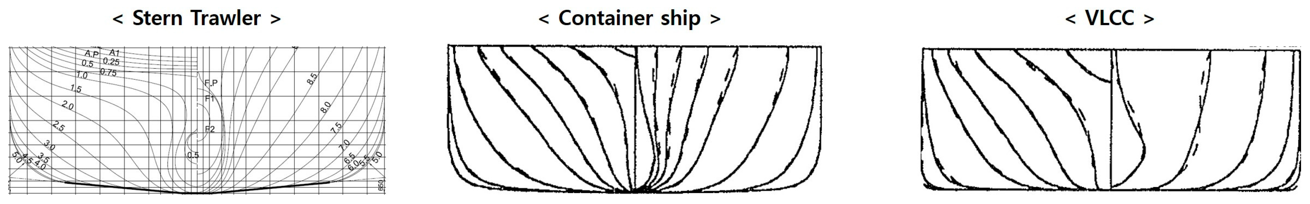
2.3. Target Ships

The target ships selected were the VLCC, container ship, and stern trawler. The reasons for choosing them are as follows:
VLCC: VLCCs are low-speed, large-capacity ships designed to transport large quantities of crude oil on a single voyage. They are characterized by a small length-to-breadth ratio ( L / B ) and a large block coefficient ( C b ) , indicating their hull shape parameters.
Container ship: Container ships are high-speed ships that are designed for rapid transportation. They have a large L / B and a small C b , highlighting their sleek and streamlined designs to optimize speed and efficiency.
Stern trawler: Similar to other fishing vessels, stern trawlers require both maneuverability and sufficient cargo space to store the catch. Therefore, they have L / B closer to that of VLCCs and C b closer to that of container ships. This balance allows them to navigate swiftly while accommodating ample fishing gear.
These target ships exhibit distinct hull form characteristics, which are summarized in Table 1, and the body plans are shown in Figure 3.

2.4. Verification of the Numerical Method

The numerical approach adopted in this study is based on the double-body potential flow theory and slender-body approximation, which have been widely applied and validated in previous studies related to ship–bank interaction [9,11,14]. These theoretical frameworks have demonstrated their reliability in predicting hydrodynamic forces and moments acting on ships navigating in restricted waters, particularly near vertical or curved boundaries.
The characteristic trends observed in the present numerical results, such as the increase in attractive forces with decreasing lateral clearance and the pronounced yaw moment sensitivity in smaller vessels, are consistent with those reported in earlier analytical and experimental works. For example, Kijima et al. and Yasukawa [10,19,20] confirmed through model tests and captive experiments that ships with fuller hull forms exhibit stronger attractive forces near bank walls, and that smaller vessels experience more abrupt moment variations under similar flow conditions.
In the case of fishing vessels, direct validation has also been addressed in the authors’ prior studies. Lee et al. experimentally investigated the maneuvering characteristics of a fishing vessel in shallow water, highlighting its sensitivity to restricted flow conditions [14]. Additionally, Kim et al. proposed empirical formulas for predicting the maneuverability of stern trawlers and confirmed their applicability through comparison with full-scale observation data [15]. The behavior patterns observed in the present study align with those earlier findings, reinforcing the validity of the current numerical approach for fishing vessels as well.
Although this study did not include direct experimental validation due to scope limitations, the alignment of the results with established hydrodynamic performance under similar assumptions provides confidence in the reliability of the employed method. Moreover, the assumptions made in this study, such as the neglect of external environmental forces and the quasi-steady condition, are consistent with conventional practices in preliminary maneuvering analyses based on potential theory.

3. Numerical Analysis of Hydrodynamic Forces and Moments

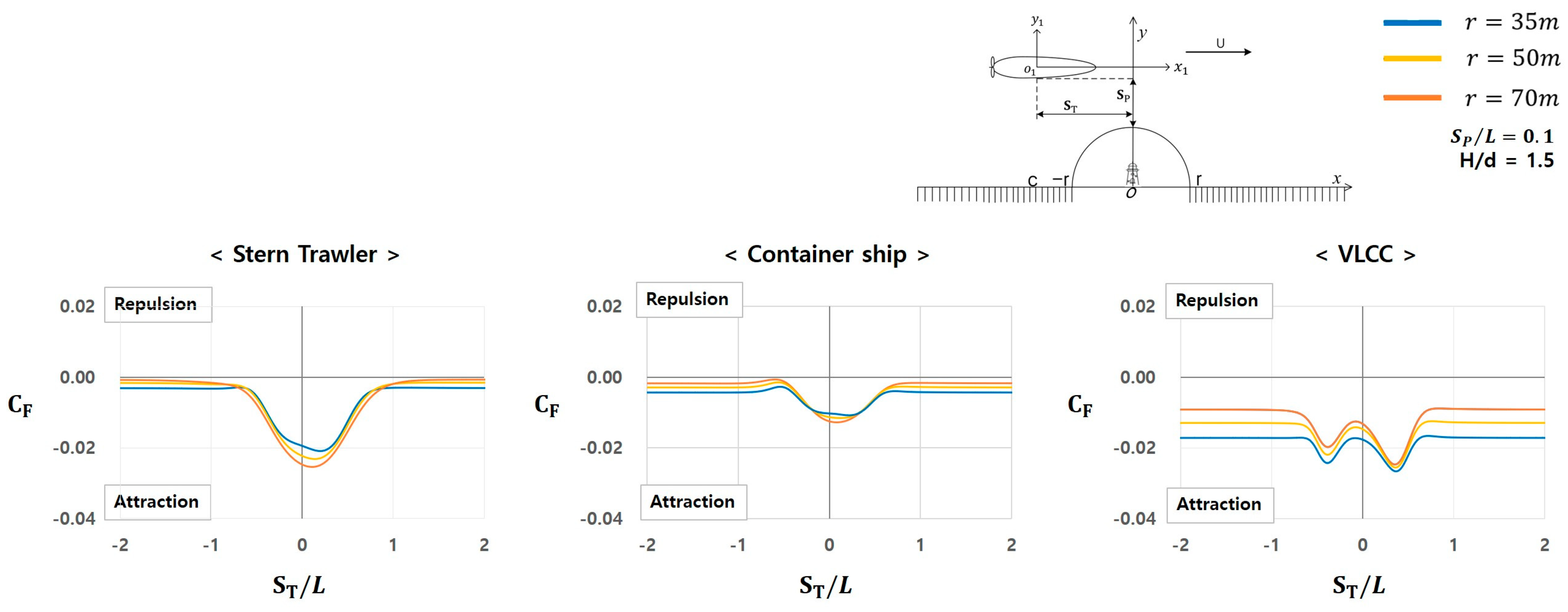
3.1. Forces and Moments Depending on the Radius of the Semi-Circular Shape

The hydrodynamic forces and moments between the target ships and the semi-circular bank wall were analyzed with variations in the radius of the semi-circular shape.
Assumption:
  • Distance from the lateral side of the hull to the semi-circular shape S P / L : 0.1 L.
  • Ratio of the water depth to the ship draft ( H / d ) : 1.5.
  • Radius of the semi-circular shape: 35, 50, and 70 m.

3.1.1. Characteristics of Hydrodynamic Forces

To analyze the influence of the semi-circular bank on maneuverability, the variation in hydrodynamic forces acting on each ship type was examined as they passed alongside the bank. This analysis provides insight into the interaction characteristics between the hull and the bank wall, which differ depending on the ship type. Figure 4 illustrates the hydrodynamic force characteristics of the target ships.
  • Stern trawler: a slight attractive force begins to develop at approximately S T / L = 2.0 , sharply increasing near S T / L = 0.5 . This force peaks after passing S T / L = 0 and then decreases near S T / L = 0.5 , eventually becoming negligible.
  • Container ship: although the magnitudes of the forces differ, the overall characteristics are similar to those of a stern trawler.
  • VLCC: exhibits relatively different characteristics from those of the stern trawler and container ship. A significant attractive force is generated at approximately S T / L = 2.0 , with the force fluctuating between increases and decreases in the range of S T / L = 1.0   t o   1.0 . Beyond S T / L = 1.0 , the force is stabilized.

3.1.2. Characteristics of Hydrodynamic Moments

The yaw moment generated during the ship’s passage near the semi-circular bank wall plays a critical role in maneuverability, as it influences heading control and turning tendency. Analyzing these moment variations helps clarify how each ship type responds to hydrodynamic effects in constrained environments. Figure 5 presents the characteristics of the yaw moment for each ship type.
  • Stern trawler: At approximately S T / L = 1.0 , the bow repulsive moment sharply increases, reaching its maximum near S T / L = 0.5 . This moment then rapidly decreases, transitioning into a bow attractive moment shortly after S T / L = 0 . The bow attractive moment peaked near S T / L = 0.5 and then diminishes, becoming negligible at approximately S T / L = 1.0 .
  • Container ship: Exhibits a trend similar to that of the stern trawler. However, the magnitude of the hydrodynamic moment is smaller than that of the stern trawler.
  • VLCC: Shows completely different characteristics from those of the stern trawler and container ship. Unlike the other two target vessels, the VLCC generates a relatively large bow repulsive moment, starting at approximately S T / L = 2.0 . This repulsive moment fluctuates between increases and decreases within the range of S T / L = 1.0   t o   1.0 and then stabilizes beyond S T / L = 1.0 . However, the phenomenon of the bow moving inward toward the bank wall from the original course does not occur.

3.1.3. Comparison of Hydrodynamic Forces and Moments Among the Target Ships

Figure 6 presents the magnitudes of the most significant forces and moments for each target ship.
As shown in Figure 6, the interaction between the ship and the bank wall is significantly influenced by the curvature of the semi-circular wall. When the radius decreased from 70 m to 35 m, the increased curvature enhanced the proximity-induced blockage effect, intensifying the asymmetry of the flow between the port and starboard sides of the hull. This resulted in greater lateral pressure differences, leading to stronger attractive forces and increased yaw moments.
Across all target ships, repulsive forces were not observed, consistent with the predictions of double-body potential flow theory, where the proximity to a wall forms image vortices that enhance suction through flow acceleration in the narrowing gap.
The VLCC generated the largest attractive force due to its large block coefficient and full-bodied hull, which produced a wider pressure drop zone near the wall. The stern trawler, with a moderately full form, showed slightly weaker forces, while the container ship, being more slender, experienced the smallest force magnitude.
As for yaw moments, the stern trawler showed the greatest repulsive moment due to its shorter length and increased susceptibility to asymmetrical pressure distributions. Interestingly, the VLCC’s moment increased as the radius widened beyond 50 m. This can be attributed to a shift in the pressure centroid aft, as the curvature effect weakened and flow reattachment occurred more downstream along the hull.

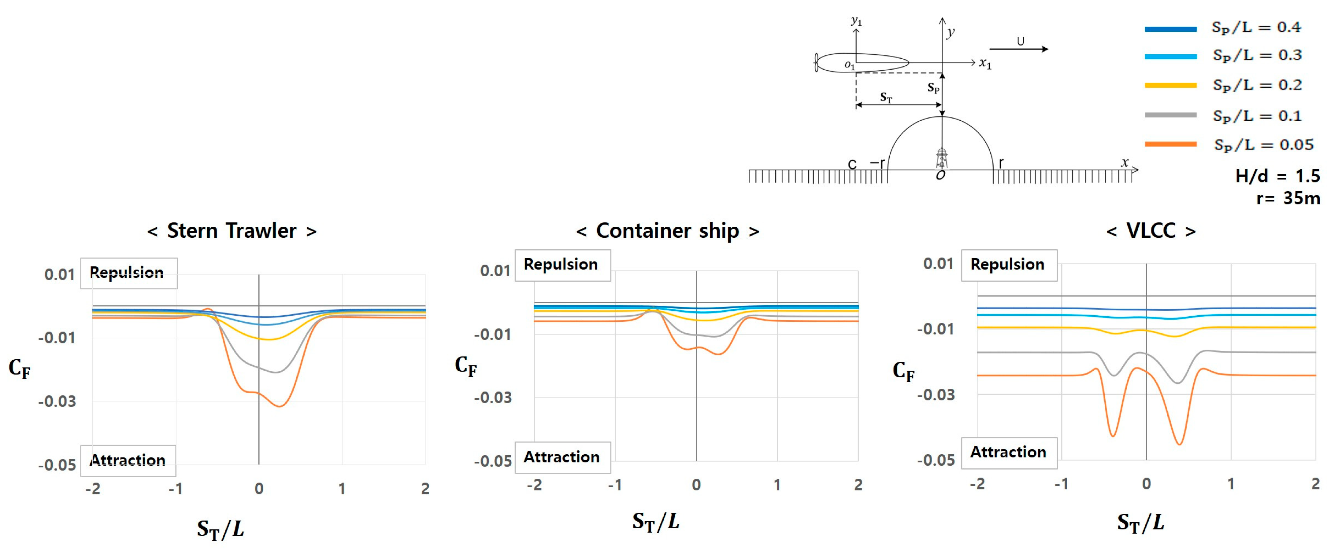
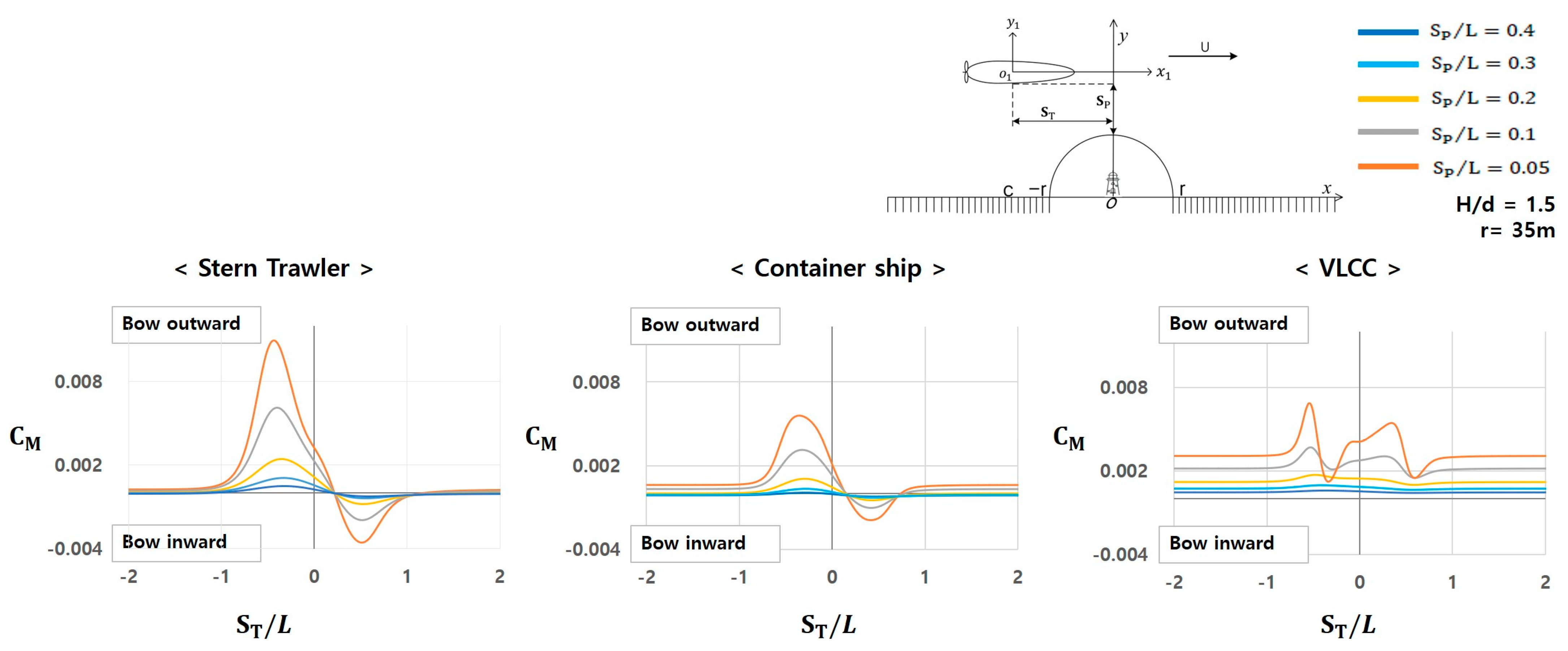
3.2. Forces and Moments Depending on the Lateral Distance from the Bank Wall

The hydrodynamic forces and moments occurring between the ships and the semicircular bank wall were analyzed based on variations in the lateral distance from the wall.
Assumption:
  • Distance from the lateral side of the hull to the semi-circular shape S P / L : 0.05, 0.1, 0.2, 0.3, and 0.4 L.
  • Ratio of the water depth to the ship draft H / d : 1.5.
  • Radius of the semi-circular shape: 35 m.

3.2.1. Characteristics of Hydrodynamic Forces

Figure 7 illustrates the characteristics of hydrodynamic forces acting on the target ships.
  • Stern trawler: A slight attractive force is generated at approximately S T / L = 2.0 , which gradually increased from S T / L = 1.0 . This force reaches its maximum near S T / L = 0.5 , then decreases, and becomes minimal at approximately S T / L = 1.0 . However, at S P / L = 0.05 , unlike the range S P / L = 0.1 t o 0.4 , the attractive force temporarily decreases near S T / L = 0.5 , and the force alternates between increasing and decreasing near S T / L = 0 . From these results, it can be concluded that the stern trawler exhibits critical hydrodynamic force characteristics at approximately S P / L = 0.05 .
  • Container ship: Overall, it exhibits characteristics similar to those of the stern trawler; however, the quantitative magnitude of the force is smaller than that of the stern trawler.
  • VLCC: Exhibits relatively different characteristics from those of the stern trawler and container ship. A significant attractive force is observed at approximately S T / L = 2 .0, which increases and decreases repeatedly in the range of S T / L = 0.5   t o   0.5 , then stabilizes at approximately S T / L = 1.0 . Additionally, the VLCC exhibits differences in the magnitudes of the hydrodynamic forces. Notably, at S P / L = 0.05 , the attractive force increases and decreases sharply between S T / L = 0.5   t o   0.5 , unlike that observed in the range S P / L = 0.1   t o   0.4 . This is considered a critical hydrodynamic force characteristic of the VLCC and requires careful attention.

3.2.2. Characteristics of Hydrodynamic Moments

Figure 8 illustrates the characteristics of the yaw moment for the target ships.
  • Stern trawler: The bow repulsive moment starts to sharply increase at approximately S T / L = 1 . 0 and reaches its maximum near S T / L = 0.5 , then decreases sharply and transitions to the bow attractive moment after S T / L = 0.0 . This attractive moment reaches its maximum near S T / L = 0.5 , begins to decrease, and becomes minimal at approximately S T / L = 1.0 .
  • Container ship: Shows a similar trend to that of the stern trawler, but its magnitude is smaller than that of the stern trawler.
  • VLCC: Shows completely different characteristics from those of the stern trawler and container ship. A relatively large bow repulsive moment occurred at approximately S T / L = 2.0 , unlike the other two target ships. This repulsive moment increases and decreases irregularly in the range of S T / L = 0.5   t o   0.5 , then stabilizes after S T / L = 1.0 . Additionally, at S P / L = 0.05 , both the quantitative magnitude and irregularity of the bow repulsive moment are increased compared with those in the range of S P / L = 0.1   t o   0.4 . However, the phenomenon of the bow moving inward toward the bank wall from the original course does not occur.

3.2.3. Comparison of Hydrodynamic Forces and Moments Among the Target Ships

Figure 9 presents the magnitudes of the most significant forces and moments for each target ship.
As S P / L decreased from 0.4 to 0.05, the gap between the ship and the wall narrowed, resulting in stronger confinement and an intensified velocity field between the surfaces. This narrowing caused an increase in the attractive hydrodynamic force for all ships, with the VLCC again exhibiting the highest magnitude. This is attributable to its larger displacement and deeper draft, which amplified the pressure drop near the bank. The container ship showed the lowest values due to its minimal blockage effect.
In terms of yaw moment, the stern trawler was most sensitive to the change in lateral distance, generating the strongest moments due to its geometric proportions. The VLCC showed a moderate increase in yaw moment as the clearance narrowed, reflecting the growing asymmetry in the pressure distribution over its long hull. The container ship remained the least affected in moment response.

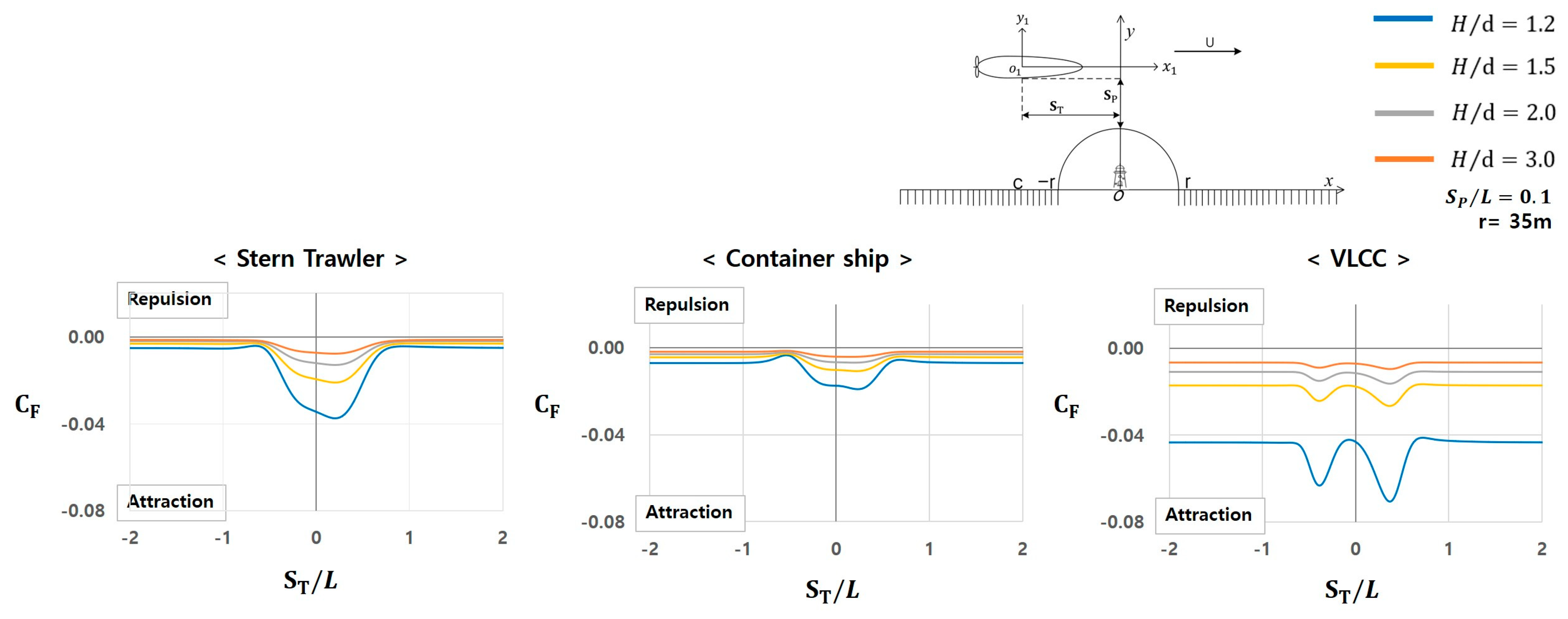
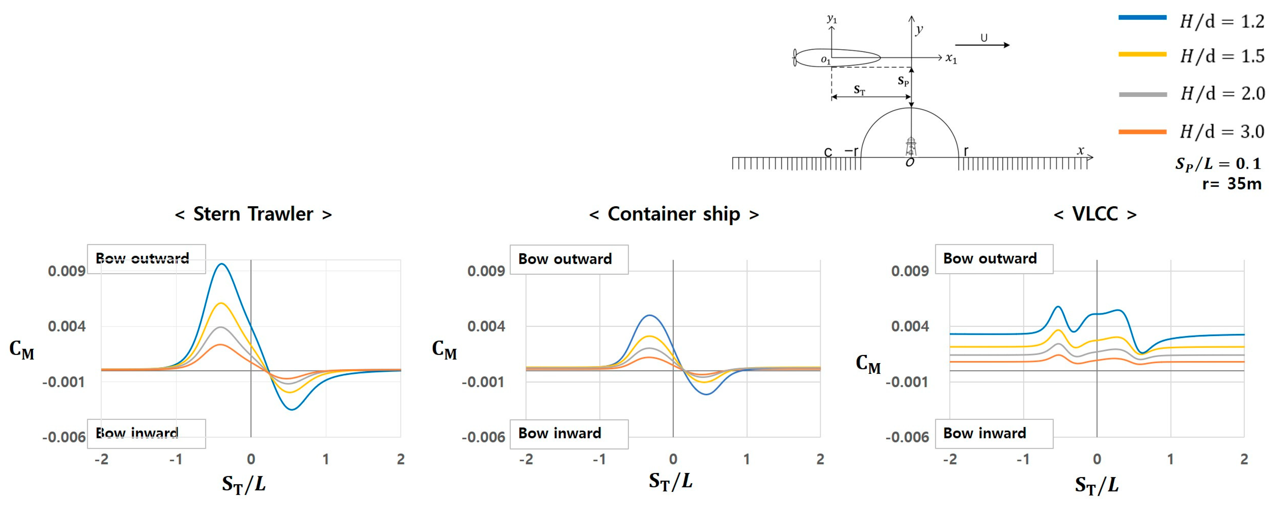
3.3. Forces and Moments Depending on Water Depth Around the Bank Wall

The hydrodynamic forces and moments occurring between the ships and the semicircular bank wall were analyzed based on variations in the water depth around the wall.
Assumption:
  • Distance from the lateral side of the hull to the semi-circular shape S P / L : 0.1 m.
  • Ratio of the water depth to the ship draft H / d : 1.2, 1.5, 2.0, and 3.0.
  • Radius of the semi-circular shape: 35 m.

3.3.1. Characteristics of Hydrodynamic Forces

Figure 10 below shows the characteristics of the hydrodynamic forces.
  • Stern trawler: A slight attractive force is observed near S T / L = 2.0 , which increases at approximately S T / L = 0.5 and reaches its maximum near S T / L = 0.5 . Subsequently, the force decreases and becomes minimal near S T / L = 1.0 .
  • Container ship: Shows a similar pattern to that of the stern trawler; however, the magnitude of the attractive force is smaller.
  • VLCC: Exhibits entirely different characteristics from those of the stern trawler and container ship. A significant attractive force occurs at approximately S T / L = 2.0 , which increases and decreases in the range of S T / L = 0.5   t o   0 . 5. Subsequently, it stabilizes at approximately S T / L = 1.0 . Furthermore, the attractive force at S P / L = 0.05 is significantly larger than that at S P / L = 0.1 t o 0.4 , which is considered a noteworthy characteristic that requires attention.

3.3.2. Characteristics of Hydrodynamic Moments

Figure 11 illustrates the characteristics of hydrodynamic yaw moments.
  • Stern trawler: The generation of the bow repulsive moment sharply increases at approximately S T / L = 1.0 , reaching its maximum magnitude near S T / L = 0.5 , then decreases again before transitioning to the bow attractive moment after S T / L = 0 . This attractive moment peaks at approximately S T / L = 0.5 before undergoing a gradual decrease.
  • Container ship: Exhibits a trend similar to that of the stern trawler, although the magnitude of the moment is relatively smaller.
  • VLCC: Shows relatively different characteristics from those of the stern trawler and container ship. A relatively large bow repulsive moment is observed at approximately S T / L = 2.0 . This repulsive moment fluctuates within the range of S T / L = 0.5   t o   0.5 before stabilizing after S T / L = 1.0 .

3.3.3. Comparison of Hydrodynamic Forces and Moments Among the Target Ships

Figure 12 illustrates the magnitudes of the largest hydrodynamic forces and moments experienced by each target ship.
As shown in Figure 12, the hydrodynamic interaction also varied with the non-dimensional water depth H / d , ranging from 1.8 to 1.2. The strongest hydrodynamic forces and moments were observed at H / d = 1.2, where the ship was closest to the seabed and the under-keel clearance was minimal.
This condition intensified flow constriction beneath the hull, accelerating the flow and reducing pressure in the lower region of the hull, thereby enhancing the suction effect. The VLCC, due to its deep draft and large wetted surface, showed a pronounced increase in attractive force at H / d = 1.2.
The stern trawler exhibited the highest repulsive and attractive yaw moments across the depth range, while the container ship consistently showed the smallest. For the VLCC, the attractive moment was almost negligible, which is likely due to the symmetrical pressure distribution along its extended hull under the quasi-steady condition.

4. Discussion

This study provides insights into the maneuvering characteristics of ships in restricted waters by numerically analyzing the hydrodynamic forces and moments acting on three different ship types—a stern trawler, container ship, and VLCC—as they navigated near a semi-circular bank wall. The findings highlight several key considerations and implications for ship navigation and maritime safety.

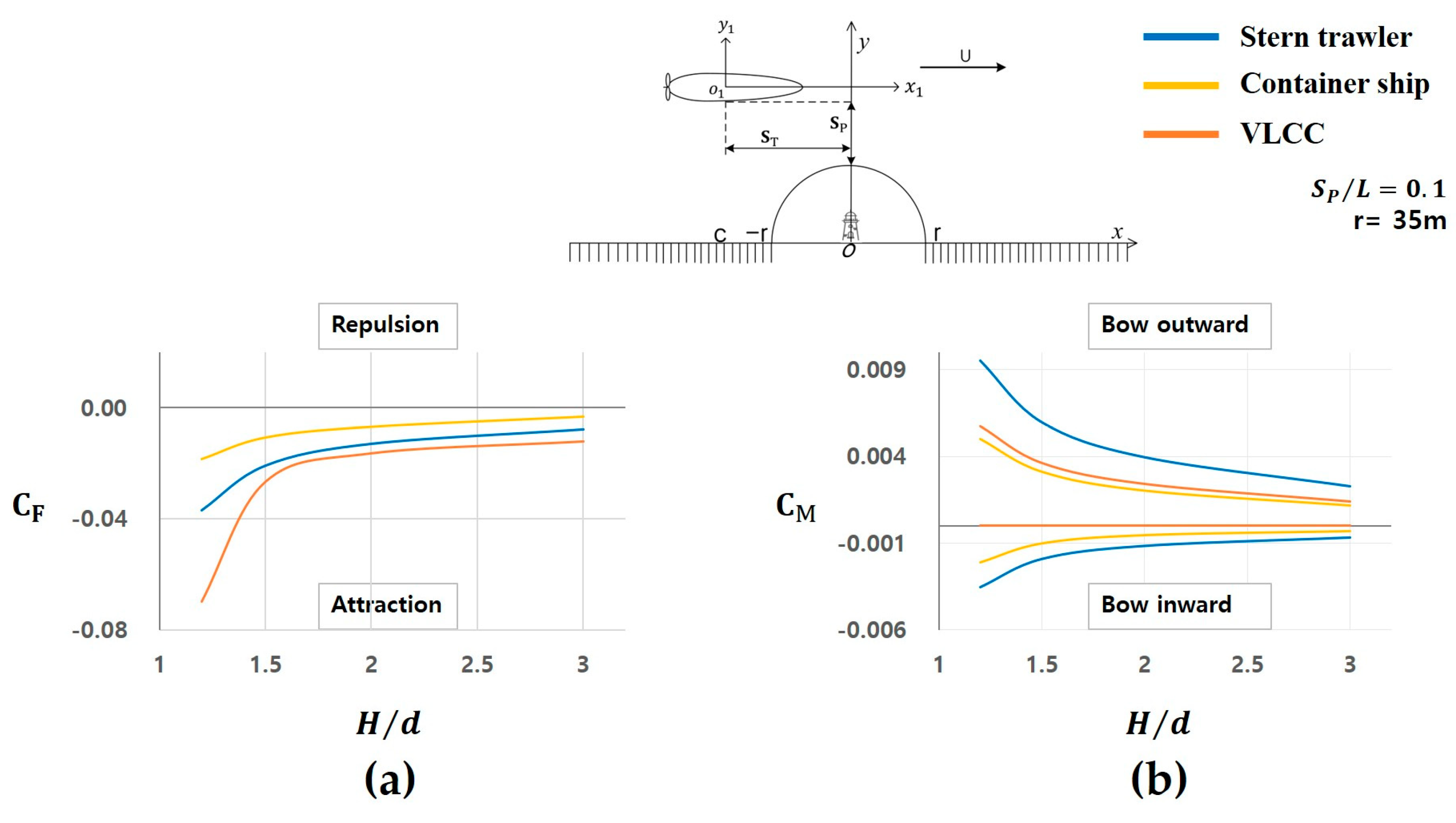
4.1. Variability in Hydrodynamic Characteristics

The results demonstrate that hydrodynamic forces and moments differ significantly among ship types due to variations in hull forms. For instance, while all ship types experienced attractive force when navigating near the bank wall, the magnitude of this force varied, with the VLCC experiencing the largest force and the container ship the smallest. These distinctions are critical for ship operators, as the magnitude of attractive force can affect the maneuver and dynamic stability of ships in restricted waters.
Hydrodynamic moments showed even greater variability, with the stern trawler exhibiting both repulsive and attractive moments under certain conditions. The unique moment characteristics of the stern trawler highlight the need for heightened awareness among operators of smaller vessels, as these variations can lead to unexpected maneuvering challenges. Conversely, the VLCC experienced minimal attractive moments, suggesting that larger ships may exhibit relatively stable moment characteristics in such situations.

4.2. Practical Implications for Navigators

The findings of this study have practical applications for ship operators, particularly pilots navigating through narrow waterways or near obstacles like bank walls. By providing comparative data on hydrodynamic forces and moments for different ship types, this research equips navigators with valuable reference points to anticipate and mitigate potential maneuvering difficulties. For instance, operators of VLCCs should prepare for significant attractive forces, while stern trawler operators need to account for dynamic moment variations.

4.3. Contribution to Maritime Safety

This study numerically analyzed the hydrodynamic interaction between ships and a semi-circular bank wall using double-body potential flow theory. Three types of ships—a stern trawler, a container ship, and a VLCC—were investigated under identical navigating conditions to understand how differences in hull form affect lateral force and yaw moment when sailing parallel to the bank.

5. Conclusions

This study compared the maneuvering characteristics of three types of ships using numerical simulations and confirmed that the stern trawler, container ship, and VLCC exhibited distinct hydrodynamic forces and moments when passing parallel to a semi-circular bank wall. The research findings are summarized as follows:
Hydrodynamic forces:
  • All three ships experienced attractive lateral forces regardless of their hull form.
  • The magnitude of the attractive force was the highest for the VLCC, which has the largest block coefficient ( C b = 0.831 ) and the lowest Froude number (Fr = 0.037), indicating a fuller hull and slower dynamic response.
  • The container ship showed the weakest force, which can be attributed to its slender hull shape with the highest length-to-breadth ratio ( L / B = 6.90 ) and a small block coefficient ( C b = 0.5717 ), reducing the blockage effect near the wall.
  • The stern trawler, with intermediate hull characteristics ( L / B = 5.52 , C b = 0.592 ), exhibited lateral forces between those of the other two ships.
Hydrodynamic moments:
  • The stern trawler experienced the most significant yaw moments. This may be due to its relatively short length and moderate breadth, making it more sensitive to asymmetrical flow near the bank.
  • The container ship showed similar moment tendencies but with reduced amplitude, likely due to its longer hull stabilizing the yaw response.
  • The VLCC, despite its large size, exhibited small yaw moments, which may be due to its greater longitudinal inertia and smoother pressure distribution along its hull.
These results demonstrate that variations in ship hull geometry, specifically the length-to-breadth ratio and block coefficient, play a crucial role in determining hydrodynamic performance near a bank wall. The study emphasizes the need to consider hull-specific interactions in restricted waters. Although simplified assumptions such as the quasi-steady approach and exclusion of environmental factors were used, the findings offer a clear theoretical understanding of hull–bank interaction effects.
Future studies will incorporate experimental validation and external environmental effects. Furthermore, the use of AI-driven predictive models is expected to enhance the applicability of these results to real-world navigation scenarios.

Author Contributions

Conceptualization, C.-K.L.; methodology, C.-K.L.; software, C.-K.L.; analysis, S.-H.K.; writing—original draft preparation, S.-H.K.; writing—reviewing and editing, S.-H.K.; supervision, C.-K.L. All authors have read and agreed to the published version of the manuscript.

Funding

This research was supported by a Research Grant of Pukyong National University (202416270001).

Data Availability Statement

The data used to support the findings of this study are available from the corresponding author.

Conflicts of Interest

The authors declare no conflicts of interest.

References

  1. Resolution MSC 137(76); Standards for Ship Manoeuvrability. IMO (International Maritime Organization): London, UK, 2002; pp. 1–6.
  2. BBC. The Cost of the Suez Canal Blockage. 2021. Available online: https://www.bbc.com/news/business-56559073 (accessed on 24 March 2025).
  3. Baric, M.; Mohovic, R.; Mohovic, D.; Pavic, V. The Simulation of Sloped Bank Effect Influence on Container Ship Trajectory. J. Mar. Sci. Eng. 2021, 9, 1283. [Google Scholar] [CrossRef]
  4. Zou, L.; Zou, Z.J. A Comparative Numerical Study of Bank Effects on a Cruise Ship in Crabbing Motion Based on URANS Method. Appl. Ocean Res. 2022, 126, 103258. [Google Scholar] [CrossRef]
  5. Delefortrie, G.; Verwilligen, J.; Eloot, K.; Lataire, E. Bank Interaction Effects on Ships in 6 DOF. Ocean Eng. 2024, 310, 118614. [Google Scholar] [CrossRef]
  6. Ma, S.J.; Zhou, M.G.; Zou, Z.J. Hydrodynamic Interaction among Hull, Rudder and Bank for a Ship Sailing Along a Bank in Restricted Waters. J. Hydrodyn. Ser. B 2013, 25, 809–817. [Google Scholar] [CrossRef]
  7. Lee, C.K.; Kang, I.K. A Study on the Hydrodynamic Interaction Forces Between Ship and Bank Wall in the Proximity of Bank. Korean Soc. Fish. Ocean Technol. 2004, 40, 73–77. Available online: http://db.koreascholar.com/Article/Detail/256465 (accessed on 24 March 2025).
  8. Yasukawa, H. Maneuvering Hydrodynamic Derivatives and Course Stability of a Ship Close to a Bank. Ocean Eng. 2019, 188, 106149. [Google Scholar] [CrossRef]
  9. Kijima, K.; Qing, H. Manoeuvering Motion of a Ship in the Proximity of Bank Wall. J. Soc. Nav. Archit. Jpn. 1987, 162, 125–132. [Google Scholar] [CrossRef] [PubMed]
  10. Kijima, K.; Furukawa, Y.; Qing, H. The Interaction Effects Between Two Ships in the Proximity of Bank Wall. Trans. West-Jpn. Soc. Nav. Archit. 1991, 81, 101–112. [Google Scholar]
  11. Kijima, K.; Furukawa, Y. A Ship Maneuvering Motion in the Proximity of Pier. In Proceedings of the International Committee on Manoeuvering and Control of Marine Craft, Southampton, UK, 7–9 September 1994; pp. 211–222. [Google Scholar]
  12. Martić, I.; Degiuli, N.; Borčić, K.; Grlj, C.G. Numerical Assessment of the Resistance of a Solar Catamaran in Shallow Water. J. Mar. Sci. Eng. 2023, 11, 1706. [Google Scholar] [CrossRef]
  13. Martić, I.; Anušić, B.; Degiuli, N.; Grlj, C.G. Numerically Investigating the Effect of Trim on the Resistance of a Container Ship in Confined and Shallow Water. Appl. Sci. 2024, 14, 6570. [Google Scholar] [CrossRef]
  14. Lee, C.K.; Kim, S.H.; Yim, J.B.; Lee, S.M. Study on the Maneuvering Characteristics of a Fishing Vessel in Shallow Water. Nav. Eng. J. 2019, 131, 95–104. [Google Scholar]
  15. Kim, S.H.; Lee, C.K.; Chae, Y.B. Prediction of Maneuverability in Shallow Water of Fishing Trawler by Using Empirical Formula. J. Mar. Sci. Eng. 2021, 9, 1392. [Google Scholar] [CrossRef]
  16. Hadi, E.S.; Tuswan, T.; Azizah, G.; Ali, B.; Samuel, S.; Hakim, M.L.; Satrio, D. Influence of the Canal Width and Depth on the Resistance of 750 DWT Perintis Ship Using CFD Simulation. Brodogradnja 2023, 74, 117–144. [Google Scholar] [CrossRef]
  17. Kaidi, S.; Smaoui, H.; Sergent, P. Numerical Estimation of Bank-Propeller-Hull Interaction Effect on Ship Manoeuvring Using CFD Method. J. Hydrodyn. Ser. B 2017, 29, 154–167. [Google Scholar] [CrossRef]
  18. Wang, C.; Diao, M.; Tong, S.; Jiang, L.; Tang, X.; Jiang, P. Numerical Simulation Study on Ship Manoeuvrability in Mountainous Rivers: Comprehensively Considering Effects of Nonuniform Flow, Shallow Water, Narrow Banks, Winds and Waves. Ocean Eng. 2024, 306, 118109. [Google Scholar] [CrossRef]
  19. Yasukawa, H. Ship Maneuvering Motions in the Proximity of Bank. Trans. West-Jpn. Soc. Nav. Archit. 2002, 104, 41–52. [Google Scholar]
  20. Yasukawa, H. Bank Effect on Ship Maneuverability in a Channel with Varying Width. Trans. West-Jpn. Soc. Nav. Arch. 1991, 81, 85–100. [Google Scholar]
  21. Yasukawa, H. Ship Manoeuvring Motions Between Two Ships Navigating in the Proximity. Trans. West-Jpn. Soc. Nav. Arch. 2002, 105, 43–54. [Google Scholar]
  22. Taylor, P.J. The blockage coefficient for flow about an arbitrary body immersed in a channel. J. Ship Res. 1973, 17, 97–105. [Google Scholar] [CrossRef]
Figure 1. Location and structure of Yongho Pier (Google Earth satellite image).
Jmse 13 01075 g001
Figure 2. Coordinate system.
Jmse 13 01075 g002
Figure 3. Body plan.
Jmse 13 01075 g003
Figure 4. Nondimensionalized forces acting on the ships depending on the radius of the semi-circular shape.
Jmse 13 01075 g004
Figure 5. Nondimensionalized moments of the ships depending on the radius of the semi-circular shape.
Jmse 13 01075 g005
Figure 6. Comparison of nondimensionalized hydrodynamic forces (a) and moments (b).
Jmse 13 01075 g006
Figure 7. Nondimensionalized forces acting on the ships depending on the lateral distance from the wall.
Jmse 13 01075 g007
Figure 8. Nondimensionalized moments of the ships depending on the lateral distance from the wall.
Jmse 13 01075 g008
Figure 9. Comparison of nondimensionalized hydrodynamic forces (a) and moments (b).
Jmse 13 01075 g009
Figure 10. Nondimensionalized forces acting on the ships depending on the water depth around the wall.
Jmse 13 01075 g010
Figure 11. Nondimensionalized moments of the ships depending on the depth around the wall.
Jmse 13 01075 g011
Figure 12. Comparison of nondimensionalized hydrodynamic forces (a) and moments (b).
Jmse 13 01075 g012
Table 1. Types of ship.
Type of the ShipL (m)B (m)d (m) L / B C b V (knot) F r
Stern trawler85.015.45.35.520.5924.00.071
Container ship175.025.3759.5026.900.57174.00.050
VLCC325.053.022.056.130.8314.00.037
Disclaimer/Publisher’s Note: The statements, opinions and data contained in all publications are solely those of the individual author(s) and contributor(s) and not of MDPI and/or the editor(s). MDPI and/or the editor(s) disclaim responsibility for any injury to people or property resulting from any ideas, methods, instructions or products referred to in the content.

