Article

An Integrated Safety Monitoring and Pre-Warning System for Fishing Vessels

by
Kun Yang
1,2,3,
Jinglong Lin
1,3,
Jianjun Ding
1,3,
Bing Zheng
2 and
Li Qin
1,2,3,*
1
Department of Information Engineering, Zhejiang Ocean University, Zhoushan 316022, China
2
Key Laboratory of Marine Environmental Survey Technology and Application, Ministry of Natural Resources, Guangzhou 510300, China
3
Ocean Connectivity Laboratory, Zhejiang Ocean University, Zhoushan 316022, China
*
Author to whom correspondence should be addressed.
J. Mar. Sci. Eng. 2025, 13(6), 1049; https://doi.org/10.3390/jmse13061049
Submission received: 1 April 2025 / Revised: 3 May 2025 / Accepted: 24 May 2025 / Published: 26 May 2025
(This article belongs to the Special Issue Recent Advances in Maritime Safety and Ship Collision Avoidance)

Abstract

:
Fishing vessels are essential for the activities of catching, moving, and storing fish. However, fishing vessel accidents claim thousands of deaths every year. This study presents a novel integrated safety monitoring and early warning system designed for fishing vessels, offering significant advancements in maritime safety through real-time alerts based on vessel attitude motion and environmental conditions. The innovation of the system lies in its dual-subsystem architecture: a sensing terminal equipped with a nine-axis sensor, temperature and humidity sensors, a GPS module, and a surveillance camera collects critical data, while a decision support subsystem processes this information via a fuzzy logic-based algorithm to generate a “danger score”. This score quantifies the vessel’s safety status, enabling the system to trigger alerts through SMS and web notifications when predefined thresholds are exceeded. Field trials in the Zhoushan Sea area confirmed the system’s effectiveness in accurately predicting safety hazards and providing timely alerts. The results highlight its potential to enhance operational safety and contribute to the digitization of fisheries management by offering reliable real-time data on vessel conditions. The system’s modular and cost-efficient design ensures it is scalable and adaptable for widespread use across the fishing industry. Our study addresses the limitations of existing technologies by providing a balanced solution that combines comprehensive sensing capabilities with real-time responsiveness and cost-effectiveness, offering a practical and innovative approach to improve fishing vessel safety.

1. Introduction

1.1. Motivation

Fisheries are becoming more and more significant in ensuring food safety, increasing employment prospects, and encouraging economic growth [1]. According to statistics from the FAO (Food and Agriculture Organization) [2], 92.3 million tons of capture fisheries were produced worldwide in 2022, with 81 million tons coming from marine fisheries and 11.3 million tons from inland fisheries. It is difficult to conduct a fishing activity on this scale without a vessel. However, the most crucial component of the contemporary fishing business is fishing vessels, which are essential for catching, moving, and storing fish [3]. The statistical results revealed that, by the end of 2022, China had a total of 511 thousand fishing vessels with a total gross tonnage of 10.31 million tons [4]. Among these vessels, 206.7 thousand are marine fishing vessels with a total gross tonnage of 9.65 million tons, and 304.4 thousand are inland fishing vessels with a total gross tonnage of 0.66 million tons.
The fishing business is one of the most hazardous occupational categories with a high fatality rate [5,6,7], with about 24,000 fishermen losing their lives in accidents every year [8,9]. In addition, compared to the majority of other industries, the fishing sector has a much higher risk of fatal accidents [10], and most of these incidents take place aboard fishing vessels [11]. Accidents involving fishing vessels have the potential to seriously harm crew members, boats, and marine ecosystems, leading to financial losses, social issues, environmental effects, and human casualties. Therefore, reviewing current procedures and identifying new ways to lower the number of incidents involving fishing vessels is essential for ensuring sustained maritime safety and transportation.
Although numerous safety monitoring systems have been proposed, several persistent limitations hinder their effectiveness in real-world fishing operations. These include high deployment and maintenance costs due to reliance on satellite communication, limited responsiveness in dynamic maritime environments, and a lack of intelligent decision-making capabilities for real-time risk assessment. Furthermore, many existing systems are not well suited for integration across vessels of different sizes and operational scales, which restricts their applicability in developing regions or small-scale fisheries.

1.2. Contributions and Novelty

To overcome these challenges, this study proposes a novel integrated safety monitoring and early warning system specifically designed for fishing vessels. The integrated system adopts a modular and cost-effective hardware architecture, supporting flexible deployment. Real-time monitoring is achieved through 4G/5G wireless communication, enabling low-latency data transmission without the need for satellite services. The system incorporates multiple sensors—including attitude, temperature, and positioning modules—as well as surveillance video. A fuzzy logic-based decision-making algorithm is applied to intelligently evaluate risk and generate timely alerts in uncertain conditions. This integrated approach enhances operational safety while maintaining affordability and scalability, making it suitable for widespread adoption in the fishing industry.
The main contributions of this paper are summarized as follows:
  • A real-time data acquisition and processing system has been developed through the integration of a nine-axis sensor, temperature and humidity sensors, a GPS module, and a surveillance camera. The integrated system is specifically designed to monitor vessel attitude, environmental conditions, and the vessel’s location. The use of 4G/5G wireless communication ensures low-latency data transmission without relying on satellite networks.
  • The system is characterized by cost-effective and modular architecture, allowing for flexible deployment and scalability across fishing vessels of different types and sizes, including those operating in small-scale or resource-limited settings.
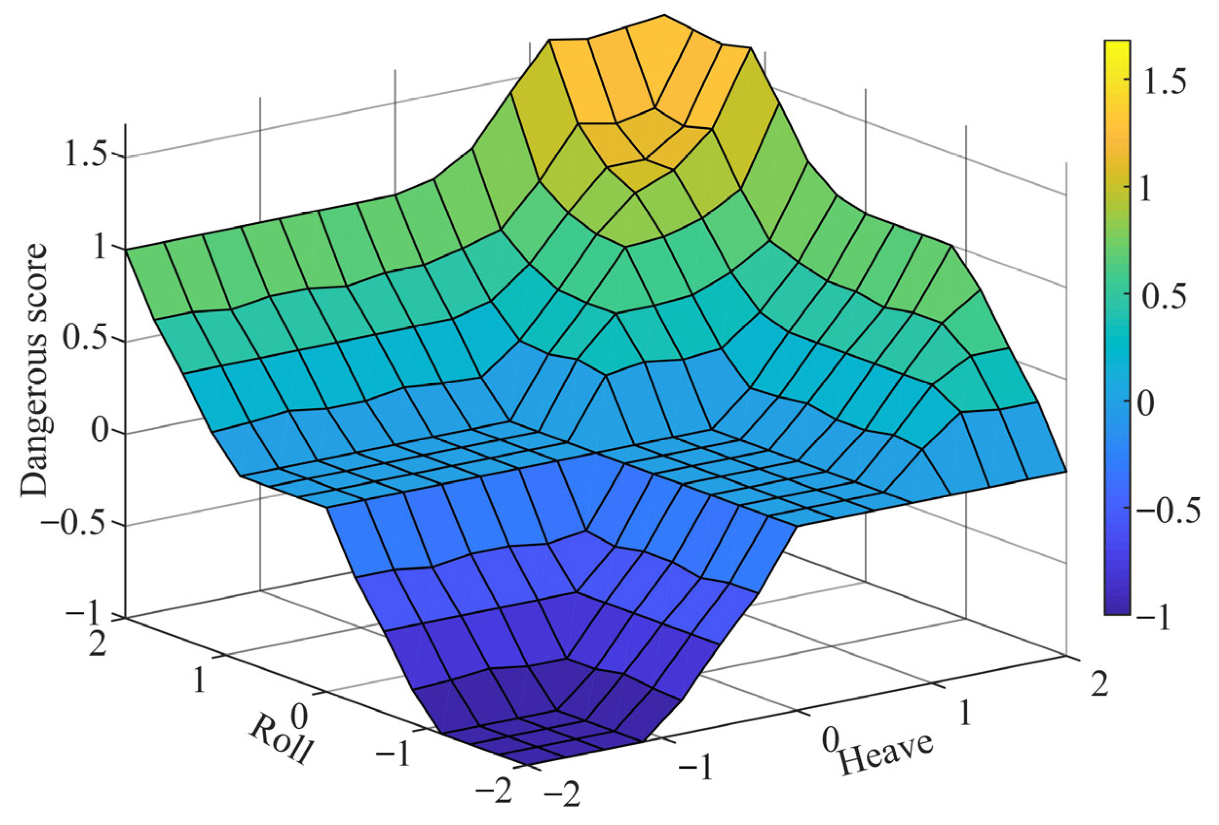
  • A fuzzy logic-based decision support algorithm is designed to compute a “danger score” for evaluating vessel safety status, effectively handling uncertainties in maritime environments and providing timely alerts to crew members.
  • Field experiments conducted in the Zhoushan Sea area validate the effectiveness of the proposed system, demonstrating its ability to improve safety.
Aside from the Introduction, this paper is divided into four sections, with the second part concentrating on the Literature Review. The hardware, software, and algorithm components are presented in Section 3, which is dedicated to the integrated system’s components. The field tests and related discussion are covered in the Section 4. Lastly, Section 5 provides a summary of the main findings.

2. Literature Review

Fishing vessel security is a key concern in diverse places, which is influenced by operator error, weather circumstances, technological variables, and environmental concerns, among others. According to Sunardi et al. [12], weather-related factors were responsible for the majority of fishing vessel accidents, including tilting and sinking episodes, which accounted for almost 60% of all incidents. Collisions and bumps, which were a representation of environmental conditions, made up about 8.9% of all events. Therefore, to protect the sustainability of fisheries resources and guarantee the safety of fishing vessels and crew members, proactive monitoring of the operational state of fishing vessels is essential. Various studies have been conducted to enhance warning systems to reduce fishing vessel accidents, thus improving the safety of fishing vessels, which can be grouped into several categories.
Various studies have been conducted to enhance the safety of fishing vessels by monitoring vessel attitude and environmental conditions. Goular et al. [13] designed a ship-borne off-axis laser warning sensor that can provide 360° protection for the entire ship. In addition, a field test was conducted to confirm the idea under operating circumstances. Qu and Zheng [14] employed a laser distance sensor and pan–tilt–zoom camera to monitor the distance of the target vessel and surrounding obstacles in real time. Liu et al. [15] used laser range finding to display real-time information, enhancing the system’s response speed and accuracy. However, this approach is linked to expensive equipment cost, making it less suitable for widespread implementation in smaller vessels.
Another category of research focuses on utilizing vision sensors for guaranteeing vessel safety. Park et al. [16] proposed a monocular vision system capable of estimating target distance through horizon detection. If the detected distance surpasses a predefined threshold, the system promptly alerts the crew to execute a course change. Bloisi et al. [17] designed a camera-based structure that allows for visual sensors to be used alone or in combination with data from vessel traffic services to create a system for monitoring vessel traffic. Chen et al. [18] accomplished the ship tracking problem by extracting robust and highly correlated ship descriptors from several ship feature sets using a multi-view learning technique. In order to ensure the safety of ships, Bi et al. [19] created a wide-field optical imaging system according to a vision-based ship speed measuring model. However, this approach is vulnerable to constraints in the field of view and target occlusion due to its high algorithm complexity, lighting and ambient requirements, and image processing and computation needs.
Another category is using telecommunication systems like the Automatic Identification System (AIS) or the Global Navigation Satellite System (GNSS). Evmides et al. [20] developed a new structure for real-time AIS data collection, processing, storing, and analysis as well as a set of algorithms for scalable and effective data collection. Pan and Deng [21] proposed a solution for monitoring the vessel status in real time using an AIS temporal database. Alba et al. [22] used a mobile device to create a localized AIS monitoring application that accurately tracks sea vessels’ locations and movements, aiding vessels safety early warning. In addition, the mobile application provides a variety of information to ensure vessel’s safety, including viewing AIS anywhere, accessing the functionalities of the AIS, and providing information on the other ships in the area of the target ship. Kazimierski and Stateczny [23] presented a data-fusion-based tracking method that uses AIS to interpret radar data, so as to enhance vessels safety early warning. Rong et al. [24] detected vessel avoided collision behavior using an enhanced sliding window method based on AIS trajectory data. The method was evaluated through three months of AIS data collected outside of China’s Ningbo-Zhoushan waters, and results indicated that the suggested model is capable of accurately extracting vessel safety early warning information. However, although AIS data offer useful information for assessing the danger of ship collisions, the AIS faces significant challenges, including security vulnerabilities, data accuracy issues, and cumbersome operations [25,26,27].
In addition, various studies focus on establishing an integrated system combined with multiple sensors to enhance maritime safety and operational efficiency by providing comprehensive, real-time monitoring and analysis. Such systems utilize various technologies to monitor vessel position, detect anomalies, and ensure safe navigation. A key advantage of these integrated systems is their applicability to small boats, where cost-effectiveness is a critical factor. Ch et al. [28] designed an inland vessel tracking system using a microcontroller, GPS, GSM, a wireless camera, vibration sensors, and ultrasonic sensors. The system notifies the base station to begin rescue operations if there is an accident. However, this system was not tested in real maritime environments to validate its effectiveness and reliability. Aronica et al. [29] presented a combined system for controlling fishing nets, their cargo, and the movement of the vessel aiming to improve on-board safety and send out early alerts in the event of potential danger. Tassetti et al. [30] developed a cost-effective and scalable tracking system for small-scale fisheries using LoRaWAN/cellular networks. The system gathered and processed positional data from small vessels, providing accurate tracking and supporting new policies for coastal resource management. However, this system has some limitations. It lacks attitude detection and 3D real-time display, which are crucial for understanding the vessel’s orientation and stability.
Most of the above studies exhibit several limitations. Some approaches depend on expensive equipment such as laser scanners or are constrained by visual occlusion, lighting, and high computational costs. Systems based on the AIS or GNSS face issues including data inaccuracy, security vulnerabilities, and complex operation. In addition, many integrated systems lack key sensing capabilities (such as attitude detection), real-time performance, or validation in real maritime environments. More importantly, few existing solutions achieve a balance between system cost, sensing completeness, data responsiveness, and deployment scalability, which is particularly critical for small- and medium-sized fishing vessels.
To address these challenges, this study proposes a comprehensive safety monitoring and early warning system tailored for fishing vessels. The system integrates a nine-axis sensor, a temperature sensor, a GPS module, and a surveillance camera, combined with wireless communication via 4G/5G to achieve real-time, low-latency monitoring and alerting. A fuzzy logic-based decision-making algorithm is adopted to handle environmental uncertainty and improve response accuracy. The proposed system emphasizes modular hardware, cost-efficiency, and intelligent risk assessment, and has been validated in field experiments conducted in the Zhoushan Sea area, China.

3. Materials and Methods

This section describes the overall architecture and operational mechanisms of the proposed intelligent pre-warning system for fishing vessels. The system is designed to monitor vessel motion and environmental data in real time, as well as evaluate safety risks based on dynamic parameters and provide timely alerts to crew members.

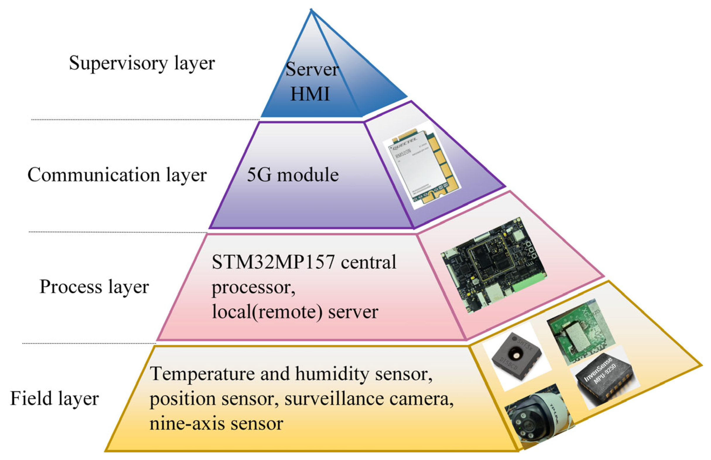
3.1. Structure of the Proposed Integrated Pre-Warning System

Figure 1 presents the general structure of the proposed integrated pre-warning system for fishing vessels. The integrated system can be divided into four layers: field layer, process layer, communication layer, and supervisory layer. Each layer is responsible for specific hardware operations and hosts corresponding software modules or algorithms that collaboratively enable real-time monitoring, analysis, and warning issuance.
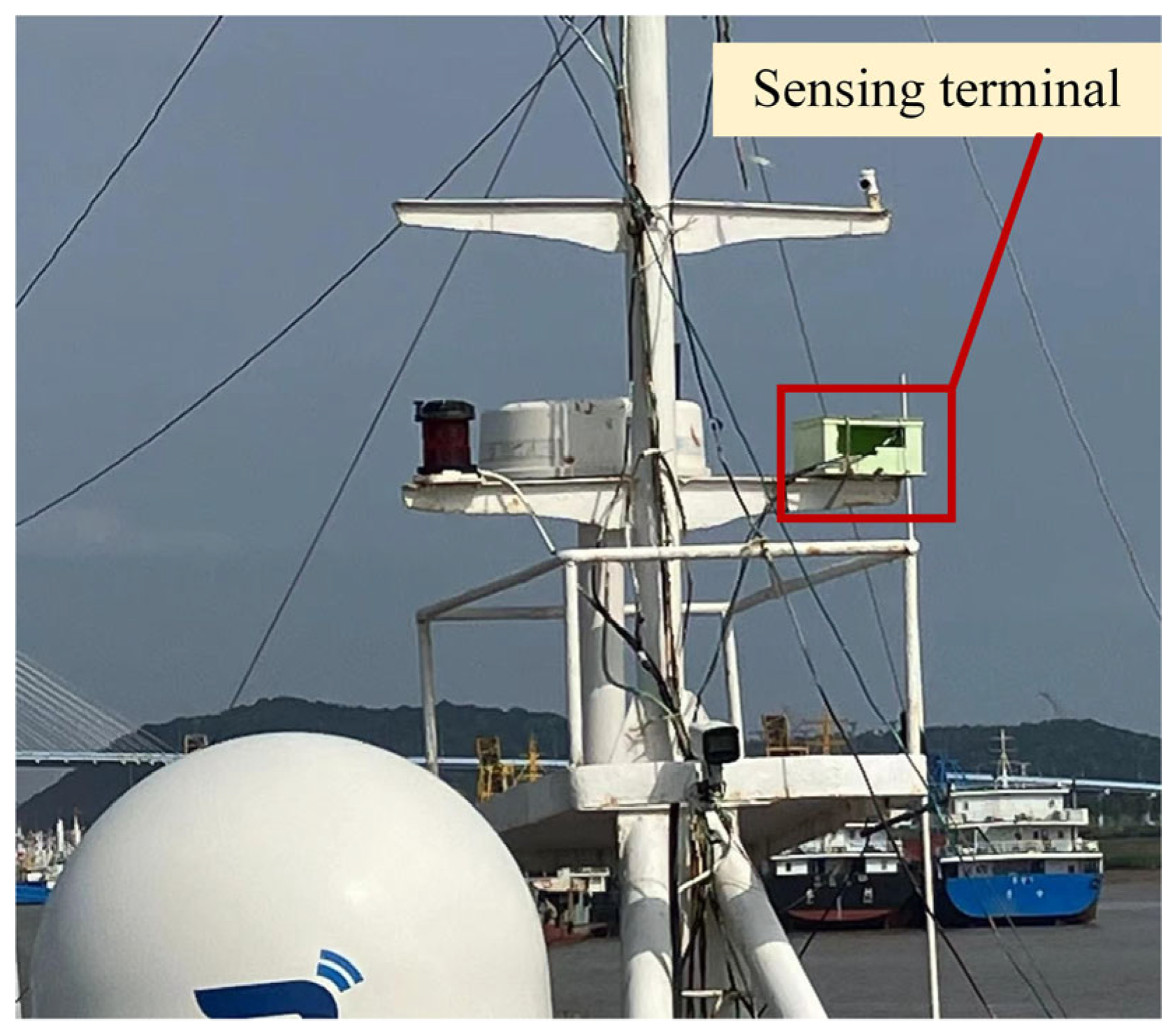
  • Field layer: This layer was employed to realize the data acquisition, directly collecting temperature, humidity, latitude, longitude, surveillance images, and vessel motion attitude (roll, pitch, and yaw angles) information by a temperature and humidity sensor, GPS, a surveillance camera and a nine-axis sensor mounted on the main deck. The collected data are transmitted to the process layer for further analysis.
  • Process layer: This layer included the STM32MP157 microprocessor that serves as the central processing unit. It handles sensor data input via serial or Ethernet ports and performs initial preprocessing, including data filtering and feature extraction. This layer accommodates several key software modules:
    • A sensor data preprocessing module, employing signal denoising techniques (e.g., Kalman filtering and moving average smoothing) to eliminate outliers and improve data reliability.
    • A multi-source data fusion module, which combines inertial and environmental information into structured data frames.
    • A local storage system, facilitating data retention.
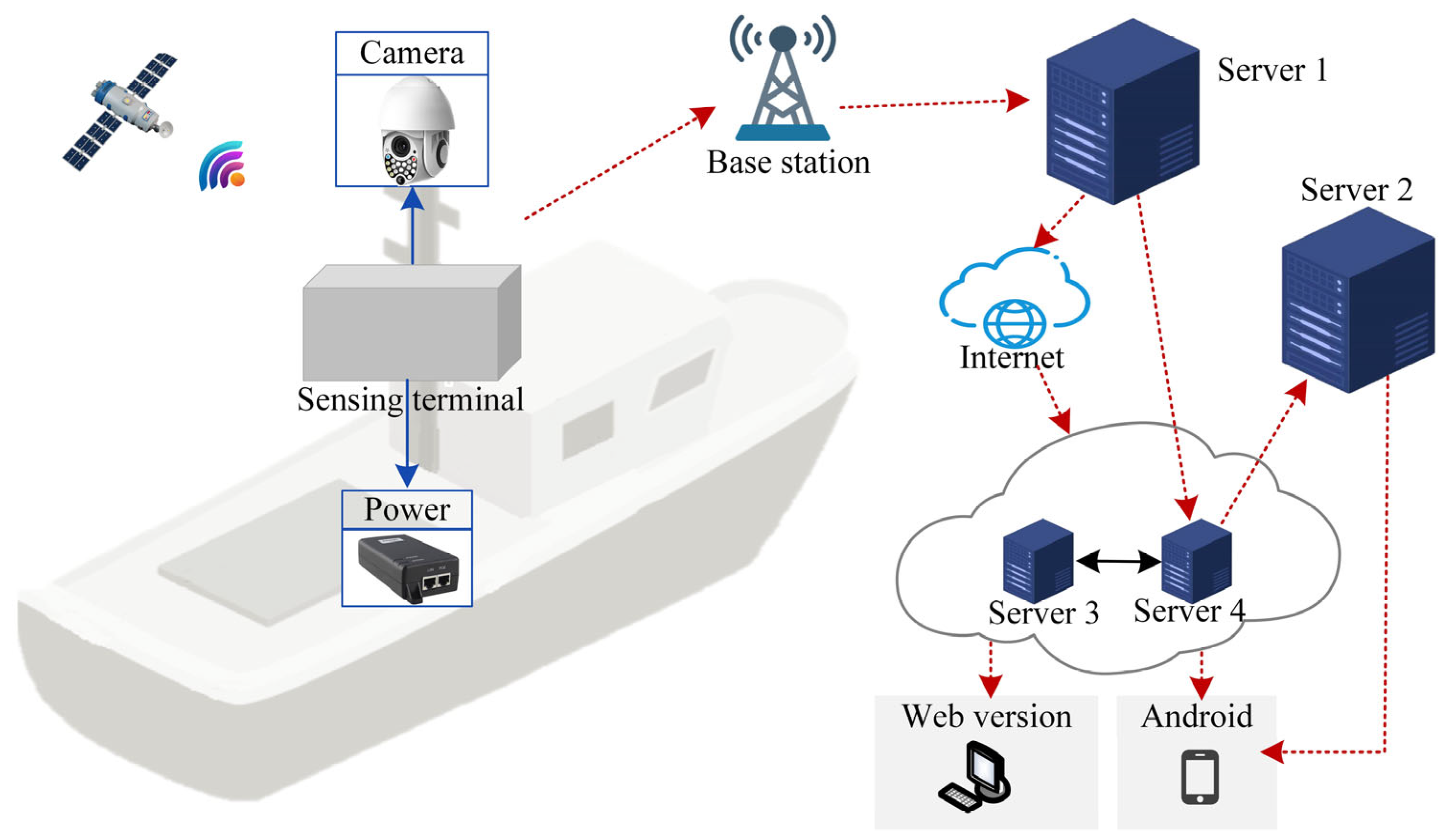
  • Communication layer: The communication layer employs a 5G module to facilitate bidirectional data transmission between the terminal and the server, enabling remote control of the terminal. This terminal can connect with shipboard sensors to receive data in real time, such as location, speed, and environmental parameters. Leveraging the high-speed and low-latency characteristics of 5G networks, it swiftly transmits the data to the shore-based base station, ensuring that shore-based personnel can promptly access the ship’s operational status.
  • Supervisory layer: This layer includes an integrated pre-warning decision support system, which is used to monitor the vessel motion attitude in real time, calculate the “danger score”, and pops up notifications or sends an SMS when attention is needed.
    • A vessel attitude anomaly assessment module, constructed using fuzzy logic inference algorithms to calculate dynamic danger levels based on real-time posture, acceleration, and environmental parameters.
    • An alert management subsystem, which compares the computed risk levels against threshold criteria and triggers corresponding alarms.
    • A graphical user interface (GUI) developed with Vue.js, and a back-end management service built on Spring Boot and MyBatis, which collectively enable real-time visualization, data querying, and remote configuration.
The specific implementation details of the hardware components, software architecture, and key algorithms adopted in each layer are elaborated in Section 3.2, Section 3.3, Section 3.4 and Section 3.5.

3.2. Hardware System Structure

Figure 2 displays the hardware schematic for the intelligent monitoring and early warning system, which was installed on the fishing vessel. The hardware included a sensing terminal (consisting of the GPS module, nine-axis sensor, temperature, and humidity sensors), power supply equipment, a monitoring camera, and four servers. The sensing terminal collects position, temperature, humidity, and vessel attitude (roll, pitch, and yaw angles). The power supply equipment powers the sensing terminal. To provide comprehensive coverage, the surveillance camera should be installed to face the vessel’s forward direction. Servers save and process the data collected from the sensing terminal and then transmit the warning information to the vessels’ crews.

3.3. Operation Mechanism for the Integrated System

Figure 3 presents the operation mechanism of an integrated safety monitoring and early warning system for fishing vessels. As observed in Figure 3, the integrated system consists of sensing terminal subsystem and decision support subsystem. In addition, the sensing terminal subsystem is composed of field layer sensors and a process layer MCU; a detailed discussion is presented in Section 3.4.
The decision support subsystem (DSS) is mainly composed of a data preprocessing module, dynamic object detection module, environmental anomaly assessment module, vessel attitude anomaly assessment module, and notification generation module. The DSS acquires environment data, vessel attitude, GPS coordinates, and surveillance images in real time. Then, the raw data from sensors are preprocessed through the data preprocessing module. The environmental anomaly assessment module analyzes the real-time data from the temperature and humidity sensors and then determines whether the environmental information is abnormal. It sends alert messages to the notification generation module if temperature and humidity exceed the threshold value. The vessel attitude anomaly assessment module analyzes the real-time data from the vessel’s sensors and predicted the attitude status of the vessel. The notification generation module displays the warning information on the web end or sends SMS alerts to the registered users if necessary. Detailed information on each control module can be found below.
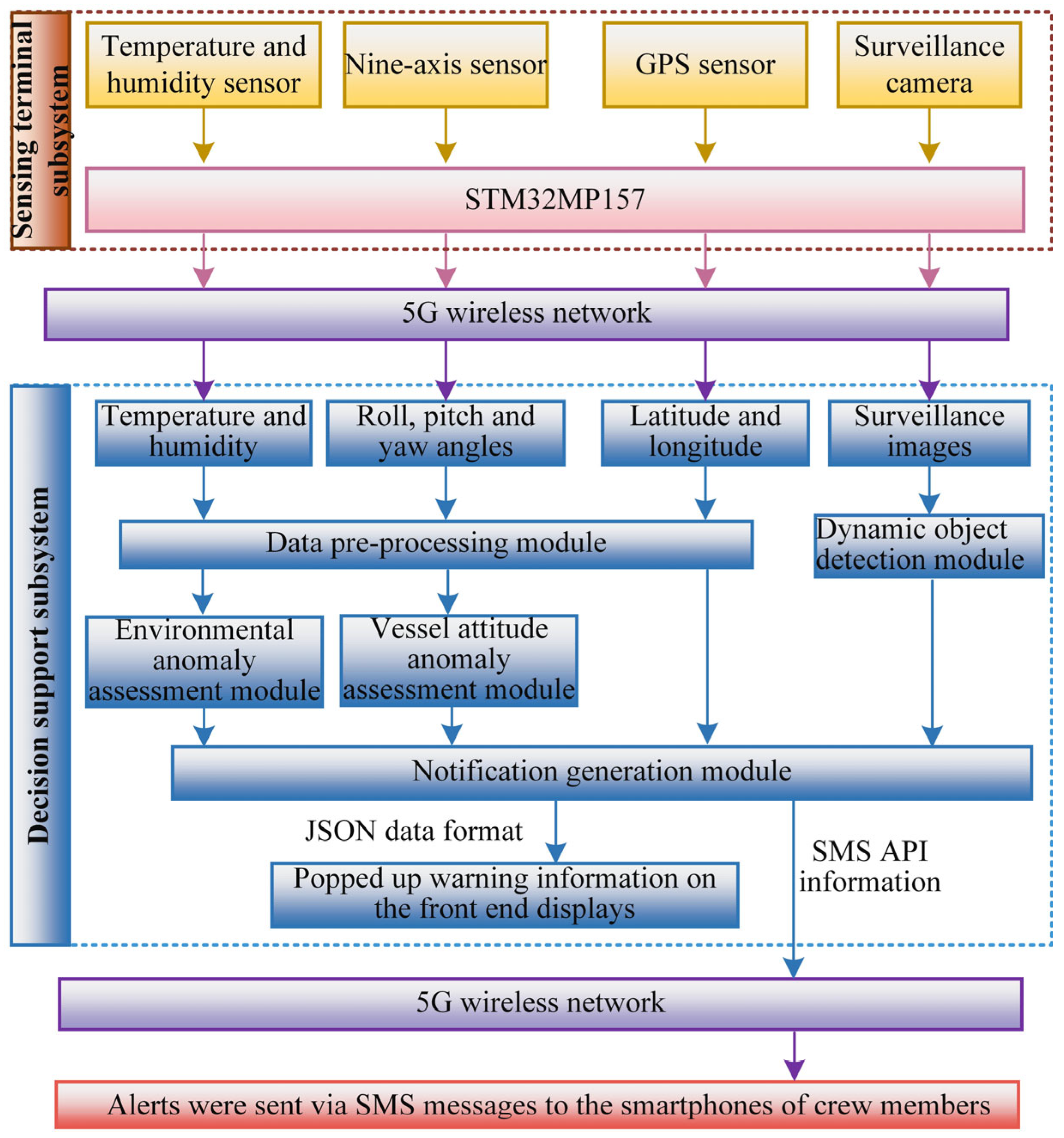
  • Data preprocessing module: Within this module, two sequential filtering processes are executed. Initially, the Kalman filter is applied to the raw data from the nine-axis sensor. Environmental data, including temperature and humidity, undergo smoothing via a moving average filter. This process entails averaging sensor readings across a designated time window to mitigate short-term fluctuations and noise, thereby enhancing data stability.
  • Vessel attitude anomaly assessment module: This module employs a fuzzy logic algorithm to calculate the “danger score” to predict the vessel’s attitude status; a detailed description can be seen in Section 3.5.2. If the “danger score” exceeds a predefined threshold, it sends alert messages to the notification generation module.
  • Dynamic object detection module: Surveillance images are employed to monitor the cockpit and deck areas. It can detect if the cockpit is unattended or if there are personnel near the deck edges, and send alert messages to notification generation module, enhancing crew safety. The intelligent detection method used in this study is provided by the surveillance camera manufacturer TP-LINK, which enables the camera to automatically trigger alerts when personnel cross predefined boundary zones near the dock edges.
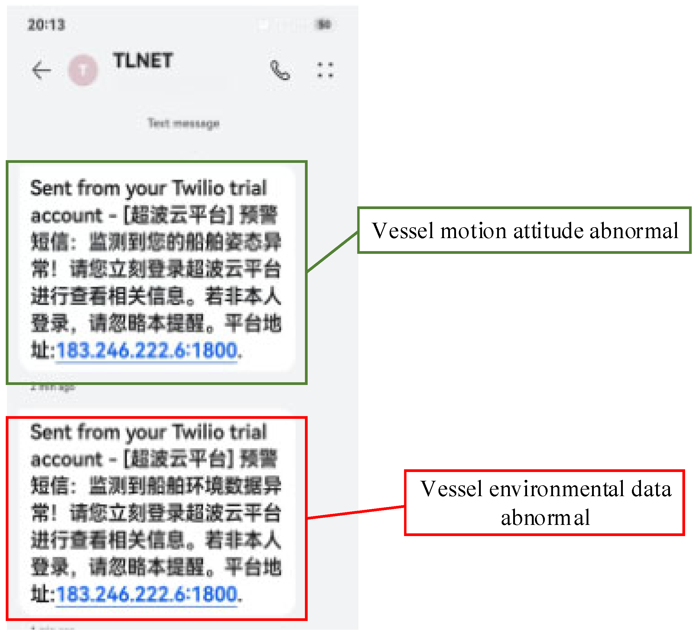
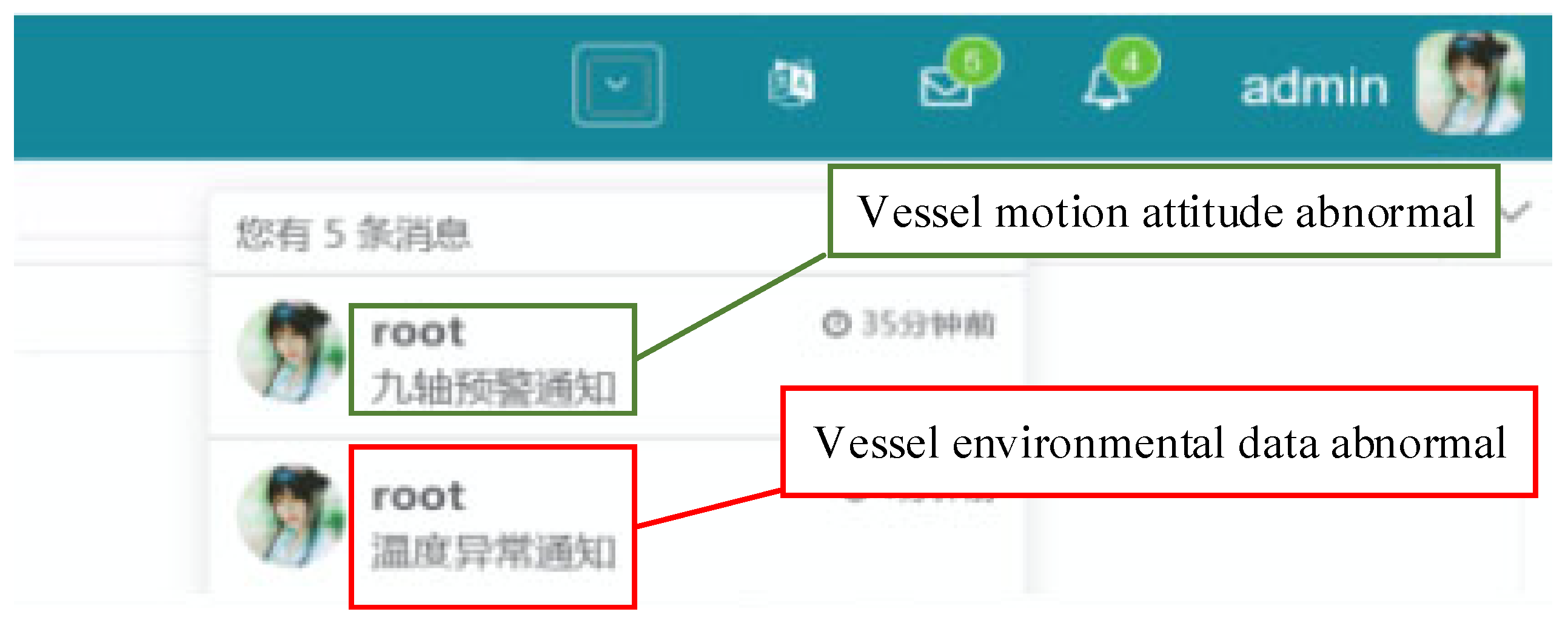
  • Notification generation module: This module employs two notification ways, SMS alerts dispatched to crew members’ smartphones and real-time safety alerts displayed on a web platform. SMS alerts encompass comprehensive information, including the hazard score, type, and recommended responses, ensuring crew members are well informed and can act promptly. The web platform complements this by offering a visual representation of the vessel’s hazard status, incorporating real-time attitude data and hazard score trends, thereby facilitating continuous monitoring and swift decision-making.

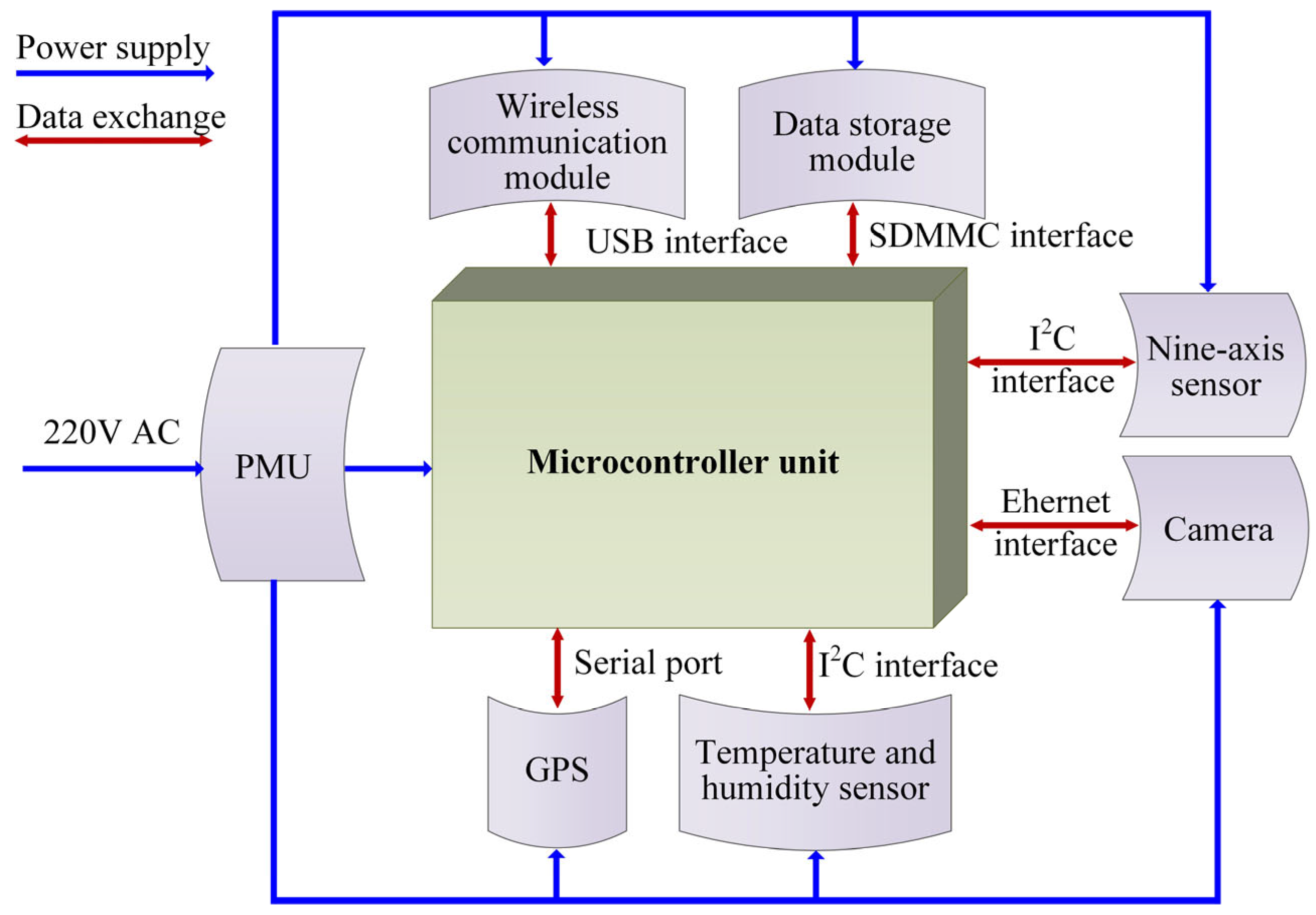
3.4. Sensing Terminal Subsystem Architecture

The sensing terminal subsystem was installed on the fishing vessel to monitor and collect critical data. Figure 4 illustrates the structure of the sensing terminal subsystem.
The subsystem comprises several key components:
  • Microcontroller Unit (module STM32MP157C): MP157C (STMicroelectronics, Grenoble, France) is a dual-core Arm® Cortex®-A7 microcontroller (up to 800 MHz) featuring Wi-Fi, Bluetooth, and multiple communication interfaces (Ethernet, USB, CAN, SPI, I2C, UART). It is powered by 12–24 VDC and programmed via STM32Cube Programmer. This study used Ethernet, USB, UART, and I2C ports. Its parameters are shown in Table 1.
  • Power management unit (PMU): The PMU (Texas Instruments, Austin, TX, USA) is used to provide appropriate DC voltages for terminal components, for example, from 220VAC to 12VDC, 12VDC to 5VDC, and 5VDC to 3.3VDC.
  • Nine-axis sensor: The JY901 provides real-time data on vessel movement, orientation, and speed. It combines a gyroscope, accelerometer, magnetometer, and digital motion sensor, delivering outputs at up to 200 Hz via the I2C interface.
  • Wireless module: The RM500Q (Quectel Wireless Solutions Co., Ltd., Shanghai, China) 5G establishes cellular communication (5G/4G/3G) between the user and the terminal. It is connected to the central processing unit via a USB port and can switch to more reliable networks during severe weather or low signal conditions.
  • Temperature and humidity sensor: SHT31 (Sensirion AG, Zurich, Switzerland) measures and reports real-time environmental temperature and humidity via the I2C interface, ensuring high accuracy and reliability [31].
  • GPS: The BD-1612Z (BnStar Electronics Co., Ltd., Shenzhen, China) module determines the vessel’s location. It operates at 2.7–3.6 VDC and connects to the MCU through a UART interface.
  • Storage module: The micro-SD memory card module (Shenzhen Atom Technology Co., Ltd., Shenzhen, China) stores data when the system cannot send them wirelessly. We can store, retrieve, and copy data when the module has problems.
  • Camera: TL-IPC633P-A (TP-LINK Technology Co., Ltd., Shenzhen, China) camera provides a wide range of monitoring (horizontal angle 345°, vertical angle 123°) to ensure comprehensive coverage, minimize vulnerabilities, and maximize vessel safety.
The itemized budget for the sensing terminal subsystem is shown in Table 2. It can be seen that the total cost is USD 399.4. In addition, the cost can be reduced to USD 303.11, except the surveillance camera, due to many fishing vessels already having installed the electronic monitoring system [32].

3.5. Decision Support Subsystem

3.5.1. Interactive Monitoring Platform

The interactive software facilitates the creation of a GUI, which was created using JavaScript, a popular programming language. The Model View Controller (MVC) framework is adopted in the control software system, which can facilitate the separation of the data logic (model), presentation (view), and user interaction (controller) to increase software development efficiency, guarantee process stability, allow for future software scalability, and improve maintainability [33].
Compared to monolithic or purely server-side architectures (e.g., PHP with embedded HTML or NET-based WebForms), the JavaScript-based MVC pattern enables better modularization and faster front-end rendering. JavaScript frameworks such as Vue.js provide reactive data binding and component-based design, allowing for more interactive and responsive interfaces. Moreover, MVC-based back-end development using Spring Boot and MyBatis supports API integration, which offers higher flexibility and interoperability across systems.
The web application architecture diagram is shown in Figure 5. The web platform consists of the front-end (client side) and back-end (server side) components and the database part.
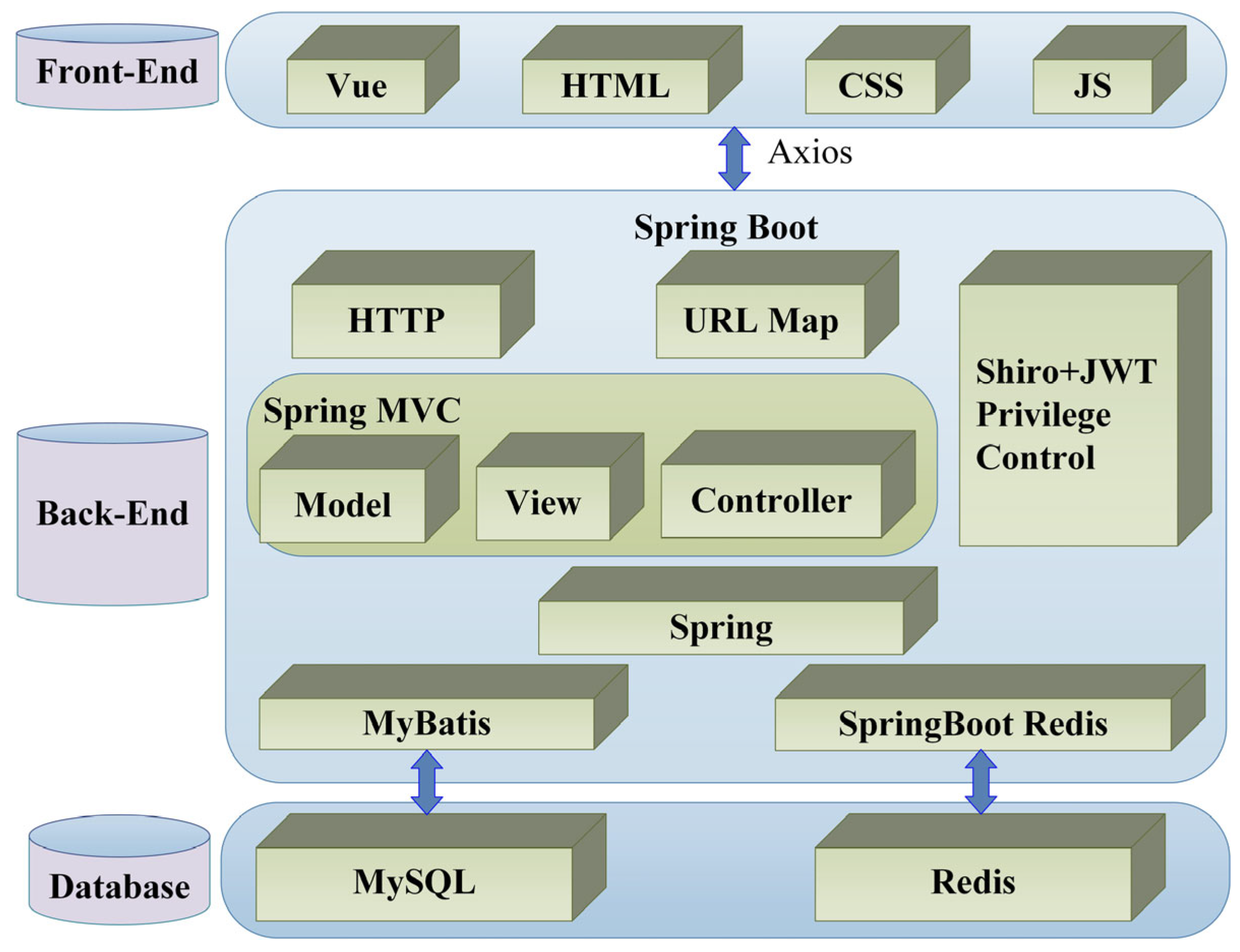
  • Front-end: This is the process of handling the user’s visual perspective. In this study, Vue.js, a lightweight framework with features of easy integration, flexibility, and efficient rendering capabilities, was adopted for web front-end development.
  • Back-end: Consists of code that communicates between the client browser and the database. In detail, this includes updating, managing, and monitoring application functionalities and data. In this study, Spring Boot, Spring MVC, and MyBatis were combined to implement the back-end platform, aiming to support a variety of widely used authentication methods, large relational and non-relational databases, a map-reduce framework, and cloud data services [34].
  • Database: A collection of data that is stored systematically and allows for querying, updating, manipulating, and managing data in a very effective and logical way. MySQL databases were used in this study.
To optimize performance and enhance system security, several supporting algorithms and strategies are implemented across the platform:
  • Database Index Optimization: B-tree indexes are strategically applied to time-series sensor data and event logs, significantly accelerating database query efficiency and ensuring timely interface response.
  • Thread Pool Algorithm: Concurrent tasks, such as sensor data parsing and alert event processing, are managed using thread pooling to prevent thread overload and improve system responsiveness under high-frequency input conditions.
  • JWT (JSON Web Token): This stateless authentication mechanism ensures secure session control, allowing for only authorized users to access protected resources and functionalities.
  • RBAC (Role-Based Access Control): Role-based permission allocation restricts system operations according to user types (e.g., admin, operator, observer), preventing unauthorized actions and improving auditability.
Figure 6 shows the homepage interface for the decision support subsystem. It can be seen from this figure that the pane is divided into five sections.
Part 1: It is located in the top left corner of the user interface, contains a series of nested menus, and provides access to a variety of functions and settings.
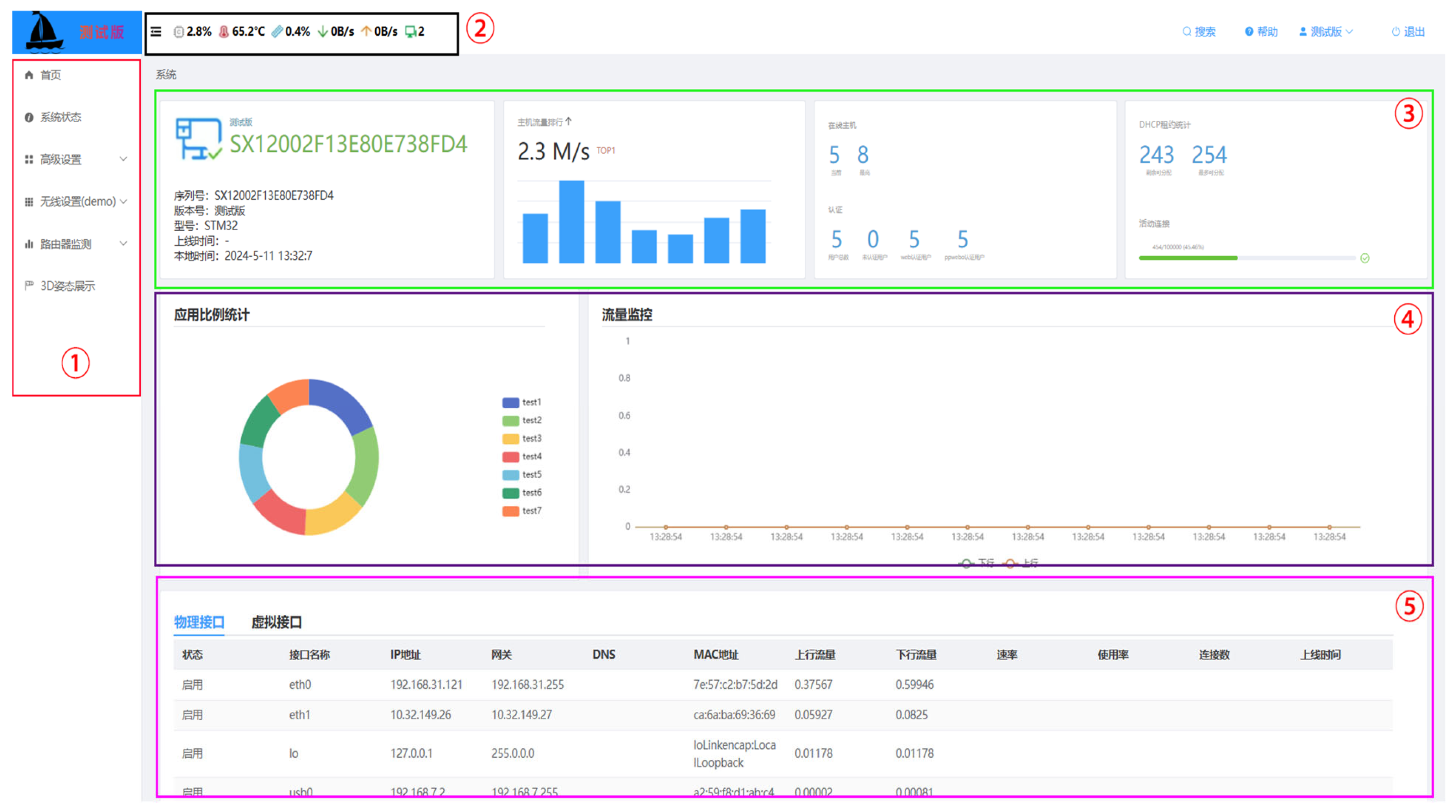
  • System status: View the status of the WAN port, 5G module, and system information (system time, uptime, hardware version, etc.).
  • Advanced settings: Configure the connection type and negotiation mode of the WAN port.
  • Wireless settings: Set the basic parameters of the 5G wireless network (network mode, SSID name, enable SSID, channel width, etc.).
  • Router monitoring: View wireless signal quality and real-time data as well as historical charts acquired from all sensors located in the vessel (temperature and humidity, acceleration, magnetometer of the vessel, surveillance image, etc.).
  • 3D visualization: Three-dimensional display of vessels’ attitude.
Part 2: View the weather, CPU temperature, humidity, etc.
Part 3: View network speed and online hosts quantities.
Part 4: View upstream and downstream traffic.
Part 5: View internet basic information (status enabled, IP address, MAC address, etc.)

3.5.2. Vessel Attitude Anomaly Assessment Method

Heaving, rolling, and pitching are the most critical parameters for describing the vessel’s attitude [35,36,37,38], which are combined to forecast the fishing vessel’s navigation safety. However, it is important to note that the sensor installed onboard does not measure heave motion directly. Instead, the heave acceleration is measured, and from these data, the vessel’s heave motion can be inferred.
The heave acceleration is a key metric in assessing the vessel’s stability and sea-keeping performance. In the fuzzy logic control model, the heave motion limits are defined in terms of acceleration, rather than displacement, as the installed nine-axis sensor (JY901) measures acceleration along with the roll and pitch angles. The heave acceleration limit is set at a roll of 20°, a pitch of 10°, and a heave acceleration of 0.65 g, which are the maximum values for safe navigation, as referenced from previous studies on vessel safety performance [39,40].
Additionally, the fuzzy logic control method is used in this study because it is robust and reasonably easy to construct, as it does not need knowledge of the precise models. The fuzzy logic system presented in this study has three input variables (heave acceleration, roll angle, and pitch angle) and one output variable (predicted danger score).
Vessel heave acceleration, H, is divided into five fuzzy subsets from 0 to 0.69 g as {heave negative big (HNB), heave negative small (HNS), heave zero (HZR), heave positive small (HPS), heave positive big (HPB)}, as listed in Table 3.
Similarly, vessel roll angle, R, is divided into five fuzzy subsets from 0° to 20° as {roll negative big (RNB), roll negative small (RNS), roll zero (RZR), roll positive small (RPS), roll positive big (RPB)}, as listed in Table 3.
Vessel pitch angle, P, is divided into five fuzzy subsets from 0° to 10° as {pitch negative big (PNB), pitch negative small (PNS), pitch zero (PZR), pitch positive small (PPS), pitch positive big (PPB)}, as listed in Table 3.
Vessel dangerous score S is an output of the fuzzy controller, for which the quantification domain is {dangerous negative big (SNB), dangerous negative small (SNS), dangerous zero (SZR), dangerous positive small (SPS), dangerous positive big (SPB)}.
The derivation of the fuzzy control rules is based on Table 3, and five examples of these criteria (a total of 5 × 5 × 5 = 125 rules) are shown in the table.
Figure 7 depicts a fuzzy decision surface that demonstrates the link between input (H, R) and output (S) using the fuzzy control rules when pitch P is constant. It can be found that if H is very high and R is very large, S will be very high. This indicates that a hazardous scenario for vessel securing could result from the combination of strong roll and big pitch motions.

4. Experiment Results and Discussion
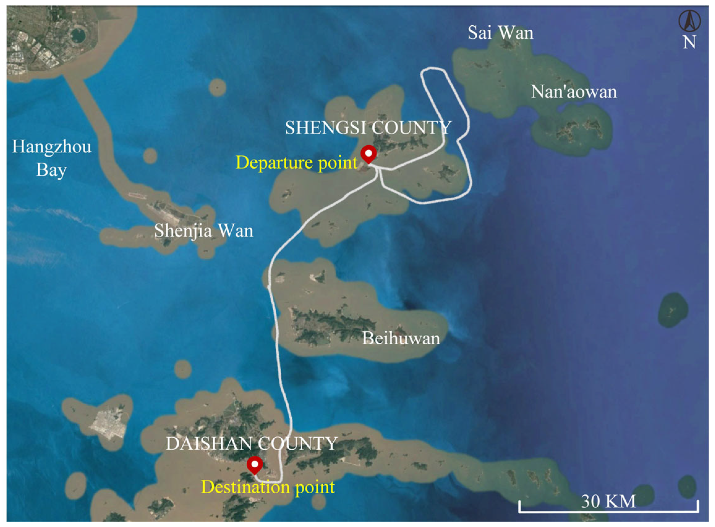
This section presents the experiment results and discussion. It first introduces the case study, including the installation of the system on a research vessel and the vessel’s navigation routes. Then, it discusses the results, focusing on vessel attitude motion prediction using the fuzzy logic method and the warning notification outcomes. These findings show the system works well in predicting hazards and giving timely alerts.

4.1. Case Study

The sensing terminal subsystem is installed in a research vessel, as shown in Figure 8. The fishing vessel has a total length of 44 m and a width of 8 m, with a maximum speed of 12 knots and a displacement of 700 t. Monitoring cameras are installed mid-mast, facing the vessel’s forward direction to provide comprehensive coverage. The power supply equipment is located inside the wheelhouse. The sensing terminal subsystem is positioned 12 m above the sea surface and is mounted on a mast bracket arm. The surveillance camera is fixed to the platform located on the lower side of the mast.
Figure 9 illustrates the navigation routes of the research vessel on 11 May 2024, between 09:00 and 15:00. The vessel’s speed seems to have been 13 knots, and the total distance traveled by the vessel is approximately 142 km.

4.2. Results and Discussion

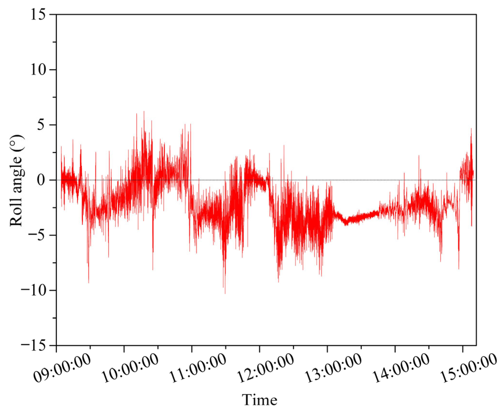
4.2.1. Vessel Attitude Motion Prediction

Figure 10 shows the vessel’s roll angle of the research vessel between 09:00 and 15:00. The length of each time interval is 1 s. It can be clearly seen that the highest roll motion is 6.25°, the minimum roll motion is −10.31°, and the roll’s average value is less than zero, indicating that the starboard side seems higher than the port side of the vessel.
Figure 11 gives the vessel’s pitch angle of the research vessel between 09:00 to 15:00. It can be found that the maximum pitch motion is 3.19° and the minimum pitch motion is −3.68°. The pitch’s average value is higher than zero, which means that the bow is more likely to sink than to rise.
Figure 12 shows the vessel’s heave acceleration of the research vessel between 09:00 and 15:00. It can be concluded that the maximum heave motion is 0.156 g and the minimum heave motion is −0.10 g, and the heave’s average value is close to zero, which suggests that the heave motion is negligibly small.
Figure 13 shows the prediction “danger score” based on data from Figure 10, Figure 11 and Figure 12 using the fuzzy logic control method. It can be found that, normally, large rolling motions occur together with large pitch motions. Furthermore, it can be concluded that during the experiment, the “danger score” is less than −1 at all times, indicating that the vessel is under a safe navigation condition. However, the decision support subsystem will send text messages to the vessel crew’s smartphones and pop up the security alert on the web platform if the “danger score” is above 1.

4.2.2. Warning Notification Result

It can be concluded that if the “danger score” calculated in the previous section is above 1, the decision support system sends an SMS warning notification to the smartphones of crew members (as shown in Figure 14 green rectangular), and a warning notification pops up on the web application platform (as shown by the green rectangle in Figure 15).
Except for the above warning for the vessel attitude motion’s danger status, if the temperature and humidity exceed the threshold value, the decision support system also sends an SMS warning notification to the smartphones of crew members (as shown by the red rectangle in Figure 14), and a warning notification pops up on the web application platform (as shown by the red rectangle in Figure 15). In addition, the GPS module provides real-time location data, enabling vessel managers to monitor the vessel’s position in real time. This helps in ensuring the vessel stays on the planned route and facilitates search-and-rescue operations if needed. The surveillance camera monitors the cockpit and deck areas. It can detect if the cockpit is unattended or if there are personnel near the deck edges, and alert the vessel managers in such situations, enhancing crew safety. These components collectively contribute to a more robust and multifaceted safety monitoring system.
Statistical analysis of 20 field trials revealed that the average latency remained consistently below 5 s from generating the “danger score” to SMS delivery. This quick response allows for the crew to take prompt action for safety. Meanwhile, shore-based managers can monitor vessel status via the web platform for timely decisions. The system thus meets the real-time demands for effective maritime safety management.

5. Conclusions

This study successfully developed an integrated safety monitoring and early warning system for fishing vessels, addressing key safety concerns through real-time data acquisition and intelligent hazard assessment. The system’s sensing terminal subsystem, incorporating a nine-axis sensor, temperature and humidity sensors, a GPS module, and a surveillance camera, demonstrated its capability to collect and transmit critical operational and environmental data. Utilizing fuzzy logic algorithms, the decision support subsystem effectively processed these data to predict potential hazards and trigger timely alerts, as evidenced by the field trials in the Zhoushan Sea area.
The findings confirmed the system’s effectiveness in enhancing vessel safety by providing accurate, real-time monitoring and early warning functions. Its modular and cost-efficient design ensures scalability and adaptability for different fishing vessel sizes and operational scales, while the integration of multi-sensor data fusion and fuzzy logic algorithms offers a significant advancement in maritime safety technology. The system’s ability to send alerts via SMS and web-based notifications ensures that crew members are promptly informed of potential risks, enabling timely interventions to prevent accidents.
In conclusion, this research contributes a robust and practical solution to improve the safety of fishing vessels, with potential for widespread application in the fishing industry. Future work could focus on expanding the system’s functionality and further optimizing its performance.

Author Contributions

K.Y.: Writing—original draft, Conceptualization, Supervision, Resources, Project administration. J.L.: Writing—original draft, Software, Formal analysis, Data curation. J.D.: Software, Validation. B.Z.: Writing—review and editing. L.Q.: Writing—review and editing, Methodology, Visualization, Funding acquisition. All authors have read and agreed to the published version of the manuscript.

Funding

This work was supported by Fund Project of Key Laboratory of Marine Environmental Survey Technology and Application, Ministry of Natural Resources [grant number MESTA-2023-B005]; Ningbo Natural Science Foundation [grant number 2023J090]; “Pioneer Leading Goose + X” Science and Technology Program of Zhejiang Province [grant number 2025C02018]; the National Natural Science Foundation of China [grant number 62341127]; and Zhoushan Science and Technology R&D Project [grant number 2024C03007].

Data Availability Statement

The original contributions presented in this study are included in the article. Further inquiries can be directed to the corresponding author.

Conflicts of Interest

The authors declare that they have no known competing financial interests or personal relationships that could have appeared to influence the work reported in this paper.

References

  1. Davis, B.; Colbourne, B.; Molyneux, D. Analysis of fishing vessel capsizing causes and links to operator stability training. Saf. Sci. 2019, 118, 355–363. [Google Scholar] [CrossRef]
  2. FAO. The State of World Fisheries and Aquaculture 2024. Blue Transformation in Action; Food and Agriculture Organization: Rome, Italy, 2024. [Google Scholar]
  3. Uğurlu, F.; Yıldız, S.; Boran, M.; Uğurlu, Ö.; Wang, J. Analysis of fishing vessel accidents with Bayesian network and Chi-square methods. Ocean. Eng. 2020, 198, 106956. [Google Scholar] [CrossRef]
  4. Zhu, E. Analysis and evaluation system research on the safety status of fishing vessel in China. Master’s Thesis, Dalian Ocean University, Dalian, China, 2024. [Google Scholar]
  5. Jin, D.; Thunberg, E. An analysis of fishing vessel accidents in fishing areas off the northeastern United States. Saf. Sci. 2005, 43, 523–540. [Google Scholar] [CrossRef]
  6. Kim, S.-H.; Ryu, K.-J.; Lee, S.-H.; Lee, K.-H.; Kim, S.-H.; Lee, Y.-W. Enhancing sustainability through analysis and prevention: A study of fatal accidents on trap boats within the commercial fishing industry. Sustainability 2023, 15, 15382. [Google Scholar] [CrossRef]
  7. Jaremin, B.; Kotulak, E. Mortality in the polish small-scale fishing industry. Occup. Med. 2004, 54, 258–260. [Google Scholar] [CrossRef]
  8. FAO. The State of World Fisheries and Aquaculture Part 2: Selected Issues Facing Fishers and Aqua Culturists; Food and Agriculture Organization: Rome, Italy, 2000; pp. 1–142. [Google Scholar]
  9. Jensen, O.C.; Petursdottir, G.; Holmen, I.M.; Abrahamsen, A.; Lincoln, J. A review of fatal accident incidence rate trends in fishing. Int. Marit. Health 2014, 65, 47–52. [Google Scholar] [CrossRef]
  10. Håvold, J.I. Safety culture aboard fishing vessels. Saf. Sci. 2010, 48, 1054–1061. [Google Scholar] [CrossRef]
  11. Petursdottir, G.; Hannibalsson, O.; Turner, J.M. Safety at Sea as an Integral Part of Fisheries Management; Food and Agriculture Organization: Rome, Italy, 2001. [Google Scholar]
  12. Sunardi, S.; Choiron, M.; Sugiarto, S.; Setyarini, P.H.; Nurwahyudi, A. Fishing vessel safety in Indonesia: A study of accident characteristics and prevention strategies. Int. J. Saf. Secur. Eng. 2024, 14, 499–511. [Google Scholar] [CrossRef]
  13. Goular, D.; Cariou, J.P.; Fleury, D.; Planchat, C.; Gouyon, R.; Besson, C.; Bêche, A.; Megaides, V. Off-axis laser warning sensor. In Proceedings of the SPIE 7323, Laser Radar Technology and Applications XIV, SPIE, Orlando, FL, USA, 15–16 April 2009; Volume 7323, pp. 314–321. [Google Scholar]
  14. Qu, X.; Zheng, W. Design of ship anti-collision alarm system based on laser range-finding. Appl. Mech. Mater. 2014, 496–500, 1502–1505. [Google Scholar] [CrossRef]
  15. Liu, X.; Qin, F.; Niu, H. Design of ship anti-collision system based on microcontroller. In Proceedings of the 7th International Conference on Applied Science, Engineering and Technology (ICASET), Qingdao, China, 20–22 May 2017; pp. 233–237. [Google Scholar]
  16. Park, J.; Cho, Y.; Yoo, B.; Kim, J. Autonomous collision avoidance for unmanned surface ships using onboard monocular vision. In Proceedings of the OCEANS 2015-MTS/IEEE Washington, Washington, DC, USA, 19–22 October 2015; pp. 1–6. [Google Scholar]
  17. Bloisi, D.D.; Previtali, F.; Pennisi, A.; Nardi, D.; Fiorini, M. Enhancing automatic maritime surveillance systems with visual information. IEEE Trans. Intell. Transp. Syst. 2017, 18, 824–833. [Google Scholar] [CrossRef]
  18. Chen, X.; Wang, S.; Shi, C.; Wu, H.; Zhao, J.; Fu, J. Robust ship tracking via multi-view learning and sparse representation. J. Navig. 2019, 72, 176–192. [Google Scholar] [CrossRef]
  19. Bi, Q.; Wang, M.; Huang, Y.; Lai, M.; Liu, Z.; Bi, X. Ship collision avoidance navigation signal recognition via vision sensing and machine forecasting. IEEE Trans. Intell. Transp. Syst. 2023, 24, 11743–11755. [Google Scholar] [CrossRef]
  20. Evmides, N.; Odysseos, L.; Michaelides, M.P.; Herodotou, H. An intelligent framework for vessel traffic monitoring using AIS data. In Proceedings of the 2022 23rd IEEE International Conference on Mobile Data Management, Paphos, Cyprus, 6–9 June 2022; pp. 413–418. [Google Scholar]
  21. Pan, Z.; Deng, S. Vessel real-time monitoring system based on AIS temporal database. In Proceedings of the 2009 International Conference on Information Management, Innovation Management and Industrial Engineering, Xi’an, China, 26–27 December 2009; pp. 611–614. [Google Scholar]
  22. Alba, J.M.M.; Dy, G.C.; Viriña, N.I.M.; Samonte, M.J.C.; Cruz, F.R.G. Localized monitoring mobile application for automatic identification system (AIS) for sea vessels. In Proceedings of the 2020 IEEE 7th International Conference on Industrial Engineering and Applications, Bangkok, Thailand, 16–21 April 2020; pp. 790–794. [Google Scholar]
  23. Kazimierski, W.; Stateczny, A. Fusion of data from AIS and tracking radar for the needs of ECDIS. In Proceedings of the 2013 Signal Processing Symposium, Serock, Poland, 5–7 June 2013; pp. 45–52. [Google Scholar]
  24. Rong, H.; Teixeira, A.P.; Soares, C.G. Ship collision avoidance behaviour recognition and analysis based on AIS data. Ocean. Eng. 2022, 245, 110479. [Google Scholar] [CrossRef]
  25. Goudossis-Goudosis, A.; Katsikas, S. Towards a secure automatic identification system (AIS). J. Mar. Sci. Technol. 2018, 24, 410–423. [Google Scholar] [CrossRef]
  26. Tassetti, A.N.; Ferrà, C.; Fabi, G. Rating the effectiveness of fishery-regulated areas with AIS data. Ocean. Coast. Manag. 2019, 175, 90–97. [Google Scholar] [CrossRef]
  27. Šimunović, L.; Kavran, Z. Automatic identification system in maritime traffic and error analysis. J. Marit. Res. 2012, 1, 77–84. [Google Scholar]
  28. Ch, S.; Kumar, M.; Yadav, N.; Kumar, N.; Shiva, S. Tracking and emergency detection of inland vessel using GPS-GSM system. In Proceedings of the 2017 2nd IEEE International Conference on Recent Trends in Electronics, Information & Communication Technology, Bangalore, India, 19–20 May 2017; pp. 2039–2042. [Google Scholar]
  29. Aronica, S.; Fontana, I.; Giacalone, G.; Basilone, G.; La Gattuta, L.; Pulizzi, M.; Genovese, S.; Mangano, S.; Calandrino, P.; Mazzola, S.; et al. iSAFETY—Integrated system for an automatic support to fishing vessel security. In Proceedings of the 2017 Intelligent Systems Conference, London, UK, 7–8 September 2017; pp. 283–287. [Google Scholar]
  30. Tassetti, A.; Galdelli, A.; Pulcinella, J.; Mancini, A.; Bolognini, L. Addressing gaps in small-scale fisheries: A Low-cost tracking system. Sensors 2022, 22, 839. [Google Scholar] [CrossRef]
  31. Viet, T.P.; Nhat, T.T.D.; Minh, Q.N.; Van, T.T.; Nguyen, A.H.; Gia, H.N.V.; Tan, N.D.; Huu, P.N. Designing of system for monitoring and forecasting air environment using LSTM model. In Proceedings of the 2024 4th International Conference of Science and Information Technology in Smart Administration, Balikpapan, Indonesia, 12 July 2024; pp. 725–729. [Google Scholar]
  32. Michelin, M.; Elliott, M.; Bucher, M.; Zimring, M.; Sweeney, M. Catalyzing the Growth of Electronic Monitoring in Fisheries; California Environmental Associates and the Nature Conservancy: Sacramento, CA, USA, 2018. [Google Scholar]
  33. Hao, L.; Zhang, J.; Ma, X. Design and implementation of simulation training system based on MVC architecture. IOP Conf. Ser. Mater. Sci. Eng. 2019, 563, 052043. [Google Scholar] [CrossRef]
  34. Madurapperuma, I.H.; Shafana, M.S.; Sabani, M.J.A. State-of-art frameworks for front-end and back-end web development. In Proceedings of the 2nd International Conference on Science and Technology, Oluvil, Sri Lanka, 24 August 2022; pp. 62–67. [Google Scholar]
  35. Cademartori, G.; Oneto, L.; Valdenazzi, F.; Coraddu, A.; Gambino, A.; Anguita, D. A review on ship motions and quiescent periods prediction models. Ocean. Eng. 2023, 280, 114822. [Google Scholar] [CrossRef]
  36. Yang, X.; Pota, H.; Garratt, M.; Ugrinovskii, V.A. Ship motion prediction for maritime flight operations. IFAC Proc. Vol. 2008, 41, 12407–12412. [Google Scholar] [CrossRef]
  37. Anguita, D.; Necrisi, R.; Sterpi, D.; Tozzi, D. A prediction of ship motions with a support vector machine. In Proceedings of the International Conference on Modeling, Identification and Control, Innsbruck, Austria, 18–21 February 2002. [Google Scholar]
  38. Song, C.; Zhang, X.; Zhang, G. Attitude prediction of ship coupled heave–pitch motions using nonlinear innovation via full-scale test data. Ocean. Eng. 2022, 264, 112524. [Google Scholar] [CrossRef]
  39. Liu, D.G.; Zheng, Z.Y.; Wu, Z.L. Review on safety assessment for ships under heavy sea. J. Traffic Transp. Eng. 2003, 3, 114–118. [Google Scholar]
  40. Wang, Y.-T.; Gu, W.-X. Safety Evaluation of Fishing Vessels in Stormy Weather. J. Dalian Ocean. Univ. 1996, 11, 15–23. [Google Scholar]
Figure 1. Integrated pre-warning system pyramid.
Jmse 13 01049 g001
Figure 2. Structure of hardware.
Jmse 13 01049 g002
Figure 3. The integrated pre-warning system operation mechanism.
Jmse 13 01049 g003
Figure 4. Structure diagram of sensing terminal subsystem.
Jmse 13 01049 g004
Figure 5. System architecture diagram.
Jmse 13 01049 g005
Figure 6. Control software interface.
Jmse 13 01049 g006
Figure 7. The fuzzy control surface of the dangerous score.
Jmse 13 01049 g007
Figure 8. Equipment installation in a research vessel.
Jmse 13 01049 g008
Figure 9. Vessel’s navigation routes.
Jmse 13 01049 g009
Figure 10. The vessel’s roll angle.
Jmse 13 01049 g010
Figure 11. The vessel’s pitch angle.
Jmse 13 01049 g011
Figure 12. The vessel’s heave acceleration.
Jmse 13 01049 g012
Figure 13. The predicted “danger score”.
Jmse 13 01049 g013
Figure 14. SMS warning notification.
Jmse 13 01049 g014
Figure 15. Alert warning interface of web application.
Jmse 13 01049 g015
Table 1. STM32MP157C module specifications.
No.MetricDescription
1MCU32-bit dual-core Arm® Cortex®-A7
2Power5 V DC
3Input/output voltage3.3 V DC
4Band650 MHZ
5WiFi protocolIEEE 802.11/a/b/g/n/
6WiFi frequency2.4 GHz to 2.497 GHz, 4.9 GHz to 5.845 GHz
7BluetoothV4.0, 2.402 GHz~2.480 GHz
8MemoryDDR3L 16/32-bit 512 MB, 4 GB eMMC
9Wireless antennaPCB
10Ethernet10 M/100 M/1000 Mbps
Table 2. Budge of the sensing terminal subsystem.
No.ItemCost = Unit × Quantities
1MCUUSD 139.40 = 139.40 × 1
2Wireless moduleUSD 123.75 = 123.75 × 1
3Surveillance cameraUSD 96.29 = 96.29 × 1
4GPS moduleUSD 4.12 = 4.12 × 1
5Temperature and humidity sensorUSD 1.10 = 1.10 × 1
6Nine axis sensorUSD 13.48 = 13.48 × 1
7CableUSD 7.5 = 0.25 × 30
8Waterproof jointUSD 4.13 = 4.13 × 1
9Sealing materialsUSD 9.63 = 9.63 × 1
TotalUSD 399.4
Table 3. Fuzzy control rules.
HNBHNSHZR
RPRPRP
PNBPNSPZRPPSPPBPNBPNSPZRPPSPPBPNBPNSPZRPPSPPB
RNBSNBSNBSNSSNSSZRRNBSNBSNBSNSSNSSZRRNBSNSSNSSZRSZRSPS
RNSSNBSNBSNSSNSSZRRNSSNBSNSSNSSZRSZRRNSSNSSNSSZRSZRSPS
RZRSNSSNSSZRSZRSPSRZRSNSSNSSZRSZRSPSRZRSZRSZRSZRSZRSPS
RPSSNSSNSSZRSZRSPSRPSSNSSZRSZRSPSSPSRPSSZRSZRSZRSPSSPS
RPBSZRSZRSPSSPSSPSRPBSZRSZRSPSSPSSPBRPBSPSSPSSPSSPBSPB
HPSHPBIf H is HNB and R is RNB and P is PNB then S is SNB.
If H is HNB and R is RNB and P is PNS then S is SNB.
If H is HNS and R is RNS and P is PNS then S is SNS.
If H is HNS and R is RNS and P is PPS then S is SZR.
RPRP
PNBPNSPZRPPSPPBPNBPNSPZRPPSPPB
RNBSNSSZRSZRSZRSPSRNBSZRSZRSPSSPSSPS
RNSSNSSZRSZRSPSSPSRNSSZRSZRSPSSPSSPB
RZRSZRSZRSZRSPSSPBRZRSPSSPSSPSSPBSPB
RPSSZRSPSSPSSPSSPBRPSSPSSPSSPBSPBSPB
RPBSPSSPSSPBSPBSPBRPBSPSSPBSPBSPBSPB
Disclaimer/Publisher’s Note: The statements, opinions and data contained in all publications are solely those of the individual author(s) and contributor(s) and not of MDPI and/or the editor(s). MDPI and/or the editor(s) disclaim responsibility for any injury to people or property resulting from any ideas, methods, instructions or products referred to in the content.

