Abstract
The proper design of wave energy converters (WECs) is crucial for ensuring robustness in harsh wave climates without incurring the additional expense of unnecessary overdesign. The power take-off (PTO) mechanism, serving as a vital link between the moving body and the electric generator, is a key component in the design load analysis of WECs. However, the setting of PTO system parameters significantly impacts the dynamic behavior of the entire WEC system, leading to alterations in estimated loads. This work is dedicated to studying the influence of PTO control strategies on the identification of extreme loads of a heaving point absorber WEC. A nonlinear time-domain model is established to estimate the dynamic responses and loads of the WEC. Both PTO loads and end-stop loads under extreme conditions are examined, considering the wave climate of a realistic sea site. The results suggest that the PTO setting strategies significantly impact the extreme load exerted on both the PTO system and the end-stop system. Varying the PTO damping within a certain range could lead to a difference of 57% and 63% in short-term extreme loads for the PTO system and the end-stop system, respectively. Furthermore, the impacts of the PTO control strategy appear to be specific to each WEC component. The PTO parameters selected for reducing the extreme PTO loads might increase the extreme end-stop loads. A holistic examination is therefore recommended for estimating the extreme loads of WECs.
1. Introduction
Ocean waves carry a tremendous amount of clean energy. Wave energy converters (WECs) are designed to generate electricity from ocean waves and are expected to play a role in the energy transition. However, the commercialization of WECs is still highly limited compared to other renewable technologies, such as offshore wind turbines. The main hurdle in developing WECs is the high levelized cost of energy (LCOE). One of the key factors of a high LCOE can be attributed to the design requirements for ensuring the reliability and survivability of WECs in oceanic climates. Reasonable designs of WECs are expected to maintain a balance between the capital cost and robustness of WECs, which is significant to the reduction in LCOE.
WECs are constantly subjected to complex and variable environmental inputs [1]. In aiming for a proper design of WECs, the design loads of the structures have to be carefully identified. Design loads of offshore structures normally refer to two aspects, namely extreme loading and fatigue loading. Fatigue loading primarily occurs in operational regions, and it is a kind of loading which accumulates strain and causes variation in stresses over the operational period due to the cyclic nature of loading. In contrast, extreme loading refers to the largest loads the WEC is likely to encounter within the designed lifespan, and it is often associated with extreme sea states [2]. Despite the significance of identifying fatigue loading in WEC designs, the present work is focused on the extreme loading of WECs. As the environmental inputs are site-specific, the load identification highly relies on the characterization of the wave climates of interest. The environment of sea sites is commonly characterized as a form of scatter diagrams in which the joint probability of various pairs of wave heights and wave periods is presented [3].
To represent extreme environmental events for all sea states within a location, contour methods are normally utilized to relate the defined return period, typically 20–25 years for offshore structures, to a contour line describing the boundary of extreme sea states. Notably, the largest loads do not necessarily occur at the highest wave, since the loads of the WEC depend on the specific wave train in each irregular sea state. Consequently, the loads imposed on the component of interest need to be examined, either by numerical or experimental approaches, for the sea states along the contour line. The sea state corresponding to the largest load of interest is identified as the extreme design condition. In addition to contour methods, other types of approaches can also be applied to extreme load calculations, including the peak over threshold (PoT) method and the full sea state analysis method [4]. Despite being built upon various statistical methods, all of these methods aim to facilitate the searching of extreme conditions.
The extreme load estimation of WECs has recently received significant research interest. These studies have drawn attention to a variety of types of WEC concepts and sea sites. In [3], a design load case study was carried out for a two-body point absorber WEC with a presumable deployment sea site near Humboldt Bay, California, USA. Based on buoy observation data, the principle component contour method was applied to derive the contour line with the desirable lifespan. Additionally, different numerical approaches, from a linear potential flow frequency-domain model and a nonlinear time-domain model, to computational fluid dynamics (CFD), were used to calculate the extreme loads of the WEC for comparison. Although the CFD model provides results fairly matching the experimental data, the low-to-middle fidelity models can approximate the extreme loads and the sea states where they occur. Given the variation in computational efficiencies of different numerical models, a framework with the progressive application of low-to high-fidelity numerical models was suggested for WEC design load assessments. In [2], a preliminary WEC load analysis was performed for a floating point absorber, and the extreme wave conditions were selected based on a contour derived by considering 100 return years. Both a CFD model and a nonlinear time-domain model, namely WEC-sim in this case, were used for load calculations. The results revealed that the extreme loads imposed on different WEC components could occur at different extreme sea states, which depend on the specific WEC design. Extreme loads on point absorbers have been studied in [5,6,7,8], in which various extreme sea states as reference and numerical models were employed. Ref. [9] reported an experimental study of the extreme loads on an overtopping WEC, in which the extreme wave conditions of a specific sea site with a return period of 100 years were considered. In [10], the extreme loads on a flap-type WEC were predicted by the high-fidelity Smoothed Particle Hydrodynamics (SPH) model. In [11], a rotating-mass type of WEC was experimentally tested for predicting extreme loads, and the wave condition was set up to represent the extreme sea states of an Italian sea site considering 10- and 100-year return periods. Ref. [12] proposed a surrogate model to accelerate the numerical estimation of extreme loads on WECs, which enables the utilization of a full sea state analysis in identifying extreme events.
Distinguishable from conventional offshore structures, such as oil and gas rigs, WECs are inherently designed to oscillate as much as possible to maximize power production. The dynamic behavior of WECs is dependent not only on the device geometry but also on the power take-off (PTO) system. The core function of PTO systems is to transfer the kinetic energy carried by the WEC buoy to mechanical or directly to electrical energy. The effect of PTO systems on the WEC motion can be separated into two orthogonal parts: PTO damping force and PTO stiffness force. The first one is the force components proportional to the buoy velocity and the latter is proportional to the buoy displacement [13,14,15]. Control strategies can be applied to manipulate these two force components during the operation of WECs for improving the power performance of WECs. A number of studies have indicated that PTO control strategies play an important role in the dynamics and further power performance of WECs [16,17,18]. For instance, as demonstrated in [19], adjusting the PTO control strategy can amplify the response by 50% to 100%. Yet, the influence of PTO control strategies has rarely been considered in the above-mentioned literature concerning the extreme load identification of WECs.
The present work is dedicated to providing insight into the effect of PTO control strategies in survival conditions on the extreme design load identification of WECs. A generic heaving point absorber is utilized as the WEC reference. A specific sea site’s defined environment contour is employed to characterize the extreme environmental inputs. A nonlinear time-domain model built upon WEC-sim software is used to estimate the responses and load of the WEC subjected to irregular wave conditions. Five distinct strategies to select PTO parameters are implemented. Based on a reference PTO damping that is optimal for power absorption, these strategies correspond to reference PTO damping values ranging from one-quarter to doubled values. Numerical simulations are conducted to estimate the design loads corresponding to different PTO control strategies. Beyond the load estimation, the study also investigates the influence of PTO control strategies on the determination of the sea state where the maximum load occurs, a crucial step in the contour method.
2. Methodology
2.1. WEC Concept Description
In this study, the utilized WEC concept refers to a floating heaving point absorber, depicted in Figure 1. Figure 2 illustrates the operation process of the WEC. The incoming waves excite the moving buoy to perform an oscillating motion. The moving part of the PTO system is connected to the buoy and drives the rotor of the electric generator to produce electricity to the grid. The end-stop mechanism takes effect once the motion of the PTO moving part is over a predefined limit. The floating buoy is simplified as a sphere with a radius of 2.5 m, with its mass assumed to equal that of the water it displaces. In wave energy conversion, the PTO system plays a pivotal role in connecting the buoy’s motion to the electrical generator. While various PTO systems with different operating principles, sizes, and efficiencies exist [20,21,22,23,24], for the purposes of this study, the PTO component in the WEC is assumed to operate in a fully linear manner. For a more elaborate integration of realistic PTO representations into the numerical modeling of WECs, relevant studies can be found in [25,26,27,28]. Another essential component in WECs is the end-stop system, which is implemented with the aim to eliminate the impact force hitting on the endpoints of the WEC structure. They are commonly applied at the two sides of the PTO system and function like a spring to prevent the moving part from exceeding the stroke [29]. Additionally, the dynamics of mooring lines and the supporting structures are assumed to be negligible to the extreme loading identifications of the PTO system and the end-stop system.
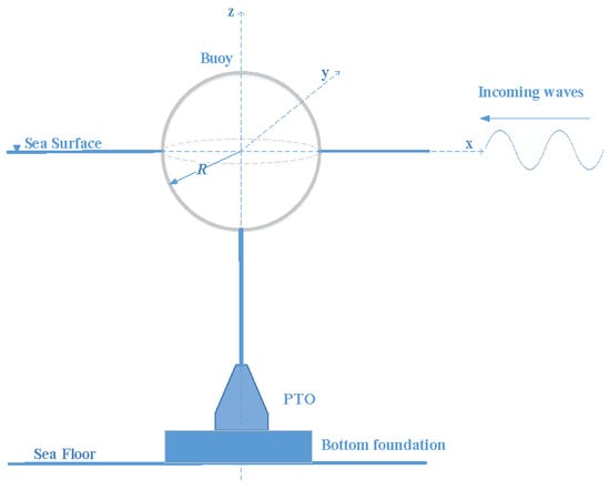
Figure 1.
Schematic of the spherical heaving point absorber with a bottom-founded PTO system.
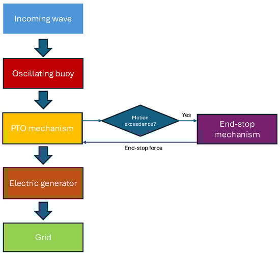
Figure 2.
Block diagram of WEC operation processes.
2.2. Numerical Modeling of the WEC
To estimate the responses and loads of the WEC, a nonlinear time-domain model is established based on the open-source software WEC-sim [30,31]. The equation of motion of the WEC is formulated based on Cummins equation [32]:
where M and are the mass of the WEC and the added mass, respectively; z, and stand for the displacement, velocity and acceleration of the buoy; t indicates the time; , , and are the excitation force, PTO reaction force, hydrostatic force and end-stop force, respectively; the convolution term on the right-hand side of the equation represents the radiation force; and is the radiation impulse function. To reduce the computational load, the convolution term is approximated by a state-space representation in the numerical integration of WEC-Sim [30]. The hydrodynamic coefficients, including excitation force coefficients, added mass and radiation impulse function, are derived based on the open-source boundary element method solver Nemoh [33,34]. The deep water assumption is applied when calculating the hydrodynamic coefficients of the WEC.
The hydrostatic force of WEC is calculated as
where stands for the hydrostatic coefficient.
The PTO system is assumed to be a passive damper, and the PTO force is expressed as
where is the PTO damping and it can be varied for different sea states.
The end-stop mechanism acts as a spring located at the two sides of the stroke of the floater or the moving part of the PTO system, and the end-stop force is given as
where and represent the end-stop spring stiffness and the stroke limit, where the end-stop mechanism begins to take effect. In this study, is set to be 200 kN/m and is set to be 1.25 m. It is acknowledged that the variation in these parameters would inevitably affect the the load and response of the WEC. Nevertheless, the purpose of the current work is to identify the influence of PTO parameters on the load estimations. Thus, it is fair to maintain consistent end-stop parameters throughout the simulations.
For the sake of better simulation accuracy, the nonlinear Froude–Krylov force and nonlinear restoring force are considered in the numerical model by a re-meshing routine method. This is realized by an advanced feature, that is, the NonlinearHydro function, embodied in WEC-Sim [31]. These two force components are re-calculated at each time step based on the instantaneous wetted surface of the WEC and the instant wave elevation. In addition, a quadratic term is included to represent the viscous drag effect on the dynamic responses of the WEC, and the drag coefficient is set as 0.6, referring to the investigation shown in [35]. Although nonlinear correction terms are incorporated into the numerical model, it is important to acknowledge that the Cummins equation-based approach is inherently based on the linear potential flow theory in which the flow is assumed to be inviscid, irrotational and non-compressible. As a consequence, highly nonlinear phenomena, such as vortex shedding and impact loading, cannot be captured by the model. To obtain a more reliable examination of the extreme loads, a complementary analysis using CFD models and experimental testing is required.
2.3. PTO Parameter Settings in Surviving Conditions
Different strategies for setting PTO parameters are implemented in this work. As demonstrated in [13,36], based on a linear representation of WECs, the optimal PTO damping maximizing the power absorption can be derived as
where is the optimal PTO damping at the specified wave frequency ; and are the frequency-dependent coefficients, namely radiation damping and intrinsic reactance. The radiation damping is numerically calculated by Nemoh, and the intrinsic reactance is expressed as
It is noted that the derived optimal PTO damping is frequency-dependent, which implies that the applicability of this method is originally limited to regular wave conditions. To suit the irregular sea states, the energy period is used corresponding to the wave period in regular waves. In addition, the derived optimal PTO damping normally applies to the operational regions of WECs, in which nonlinear effects are negligible. However, in extreme wave climates, ensuring that the WEC survives would become more relevant than maximizing power production. In this sense, the PTO damping that is optimal for power production is not necessarily optimal for the WEC’s survivability. Like all damping terms in dynamic systems, the PTO damping provides resistance to the motion of the WEC. As a consequence, the increased PTO damping tends to reduce the amplitude of WEC motion and velocity. However, it inevitably results in higher force exerted on the PTO system since the PTO force is proportional to the PTO damping value, as expressed in (3).
In extreme conditions, the high PTO force could challenge the PTO system, while the large motion challenges the end-stop system. Then, it is seen that there exists a contradiction regarding the determination of PTO parameters. To comprehend the effect of PTO damping on the extreme loads of WECs, four other strategies for setting the PTO damping are defined with reference to the PTO damping optimal for power production. Specifically, they are , , and , respectively. It is noted that the value of depends on the peak period of the sea state, and it is updated for each simulation case in this work.
2.4. Environmental Inputs
The wave resource information refers to the spectral data monitored by NDBC Buoy 46022, as further detailed in [3]. The extreme sea states are described based on the environmental contour line obtained by the principal component analysis (PCA) method considering a 50 years’ return period. The data points of the occurrence of sea states and the corresponding contour are given in Figure 3. The derivation of the extreme contour is carried out by an open-source tool, i.e., WEC Design Response Toolbox (WDRT) [37].
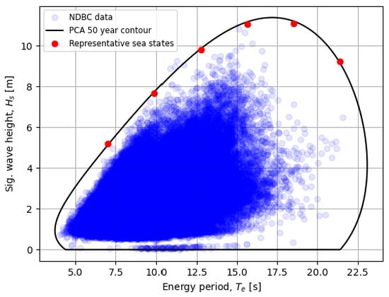
Figure 3.
Joint probability distribution of the buoy data, the derived environmental contour and selected representative sea states.
The extreme design load conditions are searched by examining the PTO loads or end-stop loads at the sea states along the contour line. To save computational time, six sea states with equal increments of energy periods are picked as the representative points for the examination, as marked in red in Figure 3. The significant wave heights and energy periods of the selected representative sea states are depicted in Table 1.

Table 1.
Parameters of the representative sea states based on the PCA contour.
This study focuses on a single sea site, aiming to investigate the effects of PTO setting strategies on the loads imposed on the end-stop and PTO systems. However, it should be noted that the extreme loading experienced by WECs is highly site-specific, as variations in sea sites lead to differing environmental inputs. Additionally, water depth, which also varies across sea sites, can influence infrastructure design, such as the mooring system or supporting platform [38,39,40]. These factors can also impact both system design and loading conditions, and the consideration of those effects would add value to future studies. Nonetheless, further discussion of these aspects lies beyond the scope of the present work.
2.5. Extreme Design Load Condition Identification
After the load and response results were calculated by the numerical model, the short-term extreme statistical analysis was implemented to predict the extreme loads at each sea state. A period of one hour was defined in each simulation case to generate the short-term response. Then, the Weibull tail-fit method was adopted to fit the statistical distribution of the short-term extreme loads. Given the derived Weibull distribution, the short-term extreme quantities of interest were then identified as the loads at the percentile of 95%. Despite the availability of other methods to estimate short-term extreme loads, the Weibull tail-fit method was adopted since it suggests a good trade-off between efficiency and prediction variance [41]. More details of the short-term extreme response analysis can be found in [3].
3. Results and Discussion
3.1. Model Verification
To verify the established numerical model in this work, the derived response amplitude operator (RAO) is compared with the experimental data reported in reference [42], which also studied a spherical buoy. Figure 4 presents a comparison between the results of the current model and those of the reference. To obtain the values of RAO, the simulation is run for various regular wave cases. To be consistent with the reference, the wave steepness in the simulations is maintained to be 0.01. As different dimensions of the sphere are considered, the wave period is normalized following Froude scaling [14,43], as shown in the horizontal axis in Figure 4. A good agreement between the current model and the reference data is observed in Figure 4, which suggests the correctness of the implementation of the WEC-Sim model in this work.
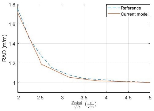
Figure 4.
RAO comparison between the established model and experimental data reported in [42].
3.2. The Influence of PTO Parameters on the Loads
To better illustrate the effect of the PTO damping on the PTO force and the end-stop force, simulations are initially performed with the implementation of regular wave conditions. As shown in Figure 5, the end-stop force starts to take effect once the WEC is displaced over the predefined stroke limit. The addition of the end-stop force affects the WEC’s velocity and further the PTO force. The PTO parameters imply no direct relationship with the end-stop force. However, the setting of PTO parameters is associated with the WEC’s motion amplitude, which acts as a trigger to the end-stop force. Figure 6 presents the variation in the WEC’s motion amplitude to the PTO damping, in which the end-stop mechanism is turned off to solely illustrate the effect of the PTO damping. It is noted that the motion amplitude of the WEC noticeably declines with the increase in the PTO damping. In principle, sufficiently large PTO damping could severely constrain the motion of the WEC to make it unlikely for the end-stop limit to be reached. The standard deviations of the PTO force and the end-stop force with different PTO parameters are presented in Figure 7. It can be seen that the standard deviation of the PTO force is approximately increased by three times when the PTO damping is changed from to . Comparatively, with the same variation in the PTO damping, the standard deviation of the end-stop force is reduced from around 170 kN to 40 kN.
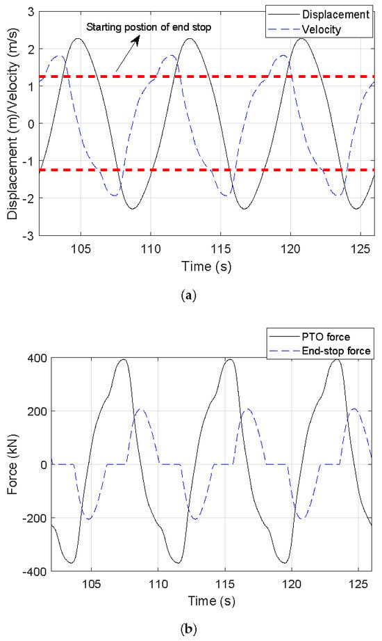
Figure 5.
Time-dependent responses and forces of the WEC under a regular wave condition by considering the end-stop mechanism. The wave height and the wave period are 4 m and 8 s, and the PTO damping is implemented as . (a) Displacement and velocity; (b) PTO and end-stop forces.
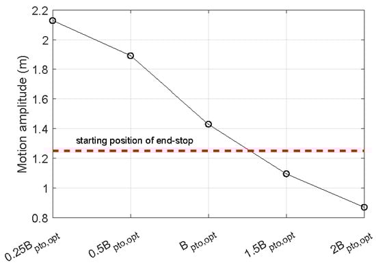
Figure 6.
The variation in the WEC’s motion amplitude with the PTO damping. The end-stop mechanism is not turned off in this case. The wave height and the wave period are 2 m and 8 s.
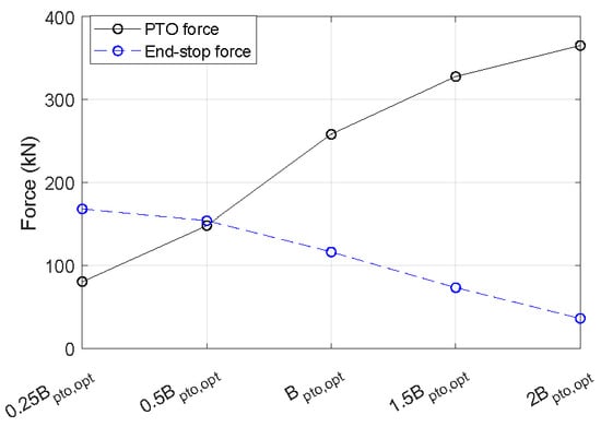
Figure 7.
The variation of the standard deviation of the PTO and end-stop forces with the PTO damping. The wave height and the wave period are 4 m and 8 s.
3.3. Extreme Load Prediction
The 1-hour extreme loads of the PTO force and the end-stop force are calculated for extreme sea states by implementing different PTO control strategies. The results are depicted in Figure 8 and Figure 9. The short-term extreme values of the PTO force and the end-stop force are dependent on the setting strategies of the PTO parameters. In particular, the increased PTO damping tends to raise the short-term extreme values of the PTO force while it contributes to the reduction in those of the end-stop force. For instance, changing the PTO damping from to at Sea State 3 results in an increase in the short-term extreme value of the PTO force from 280 kN to 440 kN, corresponding to a variation of 57%. However, further increasing the PTO damping from to results in an insignificant difference to the short-term extreme value of the PTO force. This is because the PTO damping is remarkably high. With very large PTO damping values, the PTO force tends to approach the excitation force without a noticeable increase. In the case of the end-stop force, increasing the PTO damping from to could reduce the short-term extreme value by 63%, specifically from 540 kN to 200 kN. This is because the increased PTO damping provides a stronger resistance to the motion of the WEC, and the end-stop limit tends to be less frequently triggered. Furthermore, it should be noted that the short-term extreme loads acting on the end-stop system also depend on the spring stiffness setting and the allowable stroke length. The selection of these parameters is closely tied to other design factors, including the material’s strength to withstand impact and overall manufacturing costs [44,45].
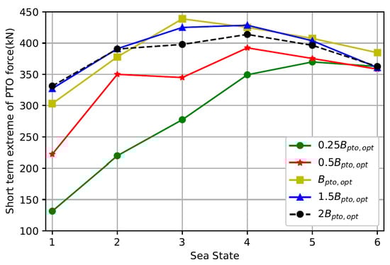
Figure 8.
The short-term extreme values of the PTO force at different sea states, in which different damping settings are implemented.
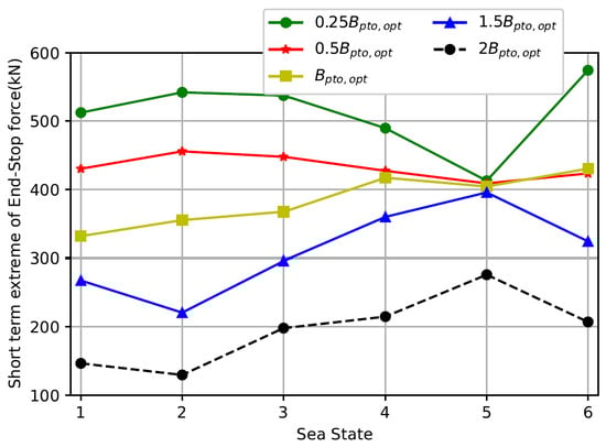
Figure 9.
The short-term extreme values of the end-stop force at different sea states, in which different damping settings are implemented.
Power absorption of the WEC is also calculated for the extreme sea states and varied PTO control strategies, as given in Figure 10. It is visible that corresponds to higher average power than other PTO damping setting strategies at most considered sea states. The figure indicates that the increased deviation of the PTO damping from reduces the power production of the WEC. For instance, and are obviously associated with lower values of the absorbed power than those where a PTO damping between and are applied. It can be observed that and exhibit a similar power production once the number of sea states is larger than 3. This can be explained by the fact that the energy period of these sea states is very large. For instance, the energy period of Sea State 4 is 15.64 s. Under such circumstances, the oscillating frequency of the WEC system is low, and its dynamics tend to behave in a stiffness-dominated manner. In this sense, the variation, from to , might be too limited to bring noticeable changes to the dynamic behavior of the WEC system. However, it should be noted that the power absorption during extreme sea states makes an insignificant contribution to the total energy production due to its negligible probability of occurrence compared to operational sea states. However, the estimation of power absorption under extreme conditions can be used to approximate the maximum power of the electrical components, such as the inverter, which the PTO system is subjected to. This could contribute to the design and sizing of relevant electrical components.
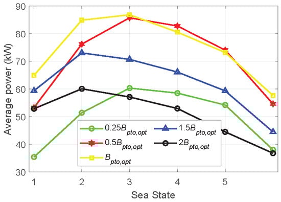
Figure 10.
The average power absorbed by the WEC at different sea states, in which different damping settings are implemented.
3.4. Extreme Design Condition Identification
Identifying the extreme design condition is an important procedure in the design load analysis of WECs. The identified condition can facilitate the definition of more specific environmental inputs for subsequent load examination by sophisticated measures, such as CFD analysis or physical testing [46,47,48]. The identified extreme design conditions are shown in Table 2. It can be seen from the table that the applied PTO parameters allow for a clear distinction in the identification of the extreme conditions for both the PTO system and the end-stop system. For instance, the PTO damping of corresponds to Sea State 5 as the extreme condition of the PTO system, while is related to Sea State 3. Therefore, it is of significance to take the PTO setting strategies into account when determining the design load conditions of WECs. In addition, it is noteworthy that the identified extreme design conditions of the PTO system are not aligned with those of the end-stop system even under identical PTO parameters. Specifically, for the PTO damping of , the extreme conditions for the PTO system and the end-stop system are identified as Sea State 3 and Sea State 6, respectively. In this sense, it should be realized that different components of WECs could be associated with different extreme design conditions. The extreme load condition identified by examining one specific component cannot be used to represent the design load condition for the holistic WEC system. Thus, it suggests the importance of covering a comprehensive range of critical components when identifying extreme load conditions.
Table 2.
The identified extreme design conditions versus PTO parameters.
4. Conclusions
The influence of PTO parameter setting strategies in surviving conditions on the extreme load identification of WECs is investigated in this work. The extreme loads on two critical components, namely the PTO system and the end-stop system, are examined using a nonlinear time-domain model in conjunction with the contour method. The conclusions are presented below.
First, the PTO setting strategies significantly impact the extreme load exerted on both the PTO system and the end-stop system. In this case, varying the PTO damping from to could result in an increase of 57% and a decrease of 63% regarding the short-term extreme loads for the PTO system and the end-stop system, respectively. This finding highlights the importance of considering the PTO setting strategy in extreme load examinations.
Secondly, the identical PTO setting strategy affects the extreme loads on the PTO system differently than on the end-stop system. Generally, increased PTO damping tends to decrease the extreme loads on the end-stop system but increases the extreme loads on the PTO system. Hence, the optimal PTO setting for reducing one type of load is not necessarily optimal for another. Therefore, it is suggested to comprehensively incorporate the interaction between PTO parameters and the related components’ loads in extreme load estimations.
Thirdly, identifying the design condition depends on the PTO setting strategy. Changing the PTO damping can alter the conditions under which the largest short-term extreme loads are predicted for both the PTO and end-stop systems. Additionally, the identified extreme conditions for the PTO system do not coincide with those for the end-stop system. This indicates the importance of extensively considering the loads on various components when determining the extreme design conditions.
Author Contributions
Conceptualization, J.T., Y.Z. and G.L.; Methodology, J.T. and Y.Z.; Software, J.T., Y.Z. and G.L.; Validation, J.T. and Y.Z.; Formal analysis, J.T.; Investigation, J.T., A.J. and G.L.; Resources, J.T. and G.L.; Data curation, G.L.; Writing—original draft, J.T.; Writing—review & editing, J.T., A.J. and G.L.; Visualization, J.T. and G.L.; Supervision, G.L.; Project administration, G.L.; Funding acquisition, G.L. All authors have read and agreed to the published version of the manuscript.
Funding
This research was funded by by the Dutch Research Council (Nederlandse Organisatie voor Wetenschappelijk Onderzoek-NWO) (EP.1602.22.001) and the CETPartnership, the Clean Energy Transition Partnership under the 2022 CETPartnership joint call for research proposals, co-funded by the European Commission (GAN°101069750) Project No CETP-2022-00127.
Data Availability Statement
The original contributions presented in this study are included in the article. Further inquiries can be directed to the corresponding author.
Conflicts of Interest
The authors declare no conflicts of interest.
Nomenclature and Abbreviations
| M | Mass |
| Added mass | |
| z, and | Displacement, velocity and acceleration |
| t | Time |
| Excitation force | |
| PTO reaction force | |
| Hydrostatic force | |
| End-stop force | |
| Radiation impulse function | |
| PTO damping | |
| End-stop spring stiffness | |
| Stroke limit | |
| Optimal PTO damping | |
| Radiation damping | |
| Intrinsic reactance | |
| Hydrostatic stiffness | |
| Angular frequency | |
| CFD | Computational fluid dynamics |
| PCA | Principal component analysis |
| PTO | Power take-off |
| SPH | Smoothed particle hydrodynamics |
| WEC | Wave energy converter |
| WDRT | WEC design response toolbox |
References
- Journée, J.M.J.; Massie, W.W.; Huijsmans, R.H.M. Offshore Hydrodynamics; Delft University of Technology: Delft, The Netherlands, 2015. [Google Scholar]
- Yu, Y.H.; Van Rij, J.; Coe, R.; Lawson, M. Preliminary wave energy converters extreme load analysis. In Proceedings of the International Conference on Offshore Mechanics and Arctic Engineering; American Society of Mechanical Engineers: St. John’s, NF, Canada, 2015; Volume 56574, p. V009T09A026. [Google Scholar]
- van Rij, J.; Yu, Y.H.; Guo, Y.; Coe, R.G. A wave energy converter design load case study. J. Mar. Sci. Eng. 2019, 7, 250. [Google Scholar] [CrossRef]
- Haselsteiner, A.F.; Coe, R.G.; Manuel, L.; Chai, W.; Leira, B.; Clarindo, G.; Soares, C.G.; Hannesdóttir, Á.; Dimitrov, N.; Sander, A.; et al. A benchmarking exercise for environmental contours. Ocean. Eng. 2021, 236, 109504. [Google Scholar] [CrossRef]
- Rafiee, A.; Fiévez, J. Numerical prediction of extreme loads on the CETO wave energy converter. In Proceedings of the 11th European Wave and Tidal Energy Conference, Nantes, France, 6–11 September 2015. Number 09A1-2. [Google Scholar]
- Katsidoniotaki, E.; Nilsson, E.; Rutgersson, A.; Engström, J.; Göteman, M. Response of point-absorbing wave energy conversion system in 50-years return period extreme focused waves. J. Mar. Sci. Eng. 2021, 9, 345. [Google Scholar] [CrossRef]
- Katsidoniotaki, E.; Shahroozi, Z.; Eskilsson, C.; Palm, J.; Engström, J.; Göteman, M. Validation of a CFD model for wave energy system dynamics in extreme waves. Ocean. Eng. 2023, 268, 113320. [Google Scholar] [CrossRef]
- Göteman, M.; Engström, J.; Eriksson, M.; Hann, M.; Ransley, E.; Greaves, D.; Leijon, M. Wave loads on a point-absorbing wave energy device in extreme waves. In Proceedings of the ISOPE International Ocean and Polar Engineering Conference, Kona, HI, USA, 21–26 June 2015; ISOPE: Mountain View, CA, USA, 2015; p. ISOPE–I. [Google Scholar]
- Parmeggiani, S.; Kofoed, J.P.; Friis-Madsen, E. Extreme loads on the mooring lines and survivability mode for the wave dragon wave energy converter. In Proceedings of the World Renewable Energy Congress 2011, Linköping, Sweden, 8–11 May 2011; Linköping University: Linköping, Sweden, 2011. [Google Scholar]
- Marrone, S.; Colagrossi, A.; Baudry, V.; Le Touzé, D. Extreme wave impacts on a wave energy converter: Load prediction through a SPH model. Coast. Eng. J. 2019, 61, 63–77. [Google Scholar] [CrossRef]
- Sirigu, S.A.; Bonfanti, M.; Begovic, E.; Bertorello, C.; Dafnakis, P.; Giorgi, G.; Bracco, G.; Mattiazzo, G. Experimental investigation of the mooring system of a wave energy converter in operating and extreme wave conditions. J. Mar. Sci. Eng. 2020, 8, 180. [Google Scholar] [CrossRef]
- Nguyen, P.T.; Manuel, L.; Coe, R.G. On the development of an efficient surrogate model for predicting long-term extreme loads on a wave energy converter. J. Offshore Mech. Arct. Eng. 2019, 141, 061103. [Google Scholar] [CrossRef]
- Tan, J.; Polinder, H.; Laguna, A.J.; Wellens, P.; Miedema, S.A. The Influence of Sizing of Wave Energy Converters on the Techno-Economic Performance. J. Mar. Sci. Eng. 2021, 9, 52. [Google Scholar] [CrossRef]
- Pecher, A. Handbook of Ocean Wave Energy; Springer Nature: Cham, Switzerland, 2017; Volume 7. [Google Scholar] [CrossRef]
- Tan, J.; Polinder, H.; Wellens, P.; Miedema, S. A feasibility study on downsizing of power take off system of wave energy converters. In Developments in Renewable Energies Offshore; CRC Press: Boca Raton, FL, USA, 2020; pp. 140–148. [Google Scholar]
- Ringwood, J.V.; Bacelli, G. Numerical optimal control of wave energy converters. IEEE Trans. Sust. Eng. 2014, 6, 294–302. [Google Scholar]
- Bacelli, G.; Coe, R.G. Comments on control of wave energy converters. IEEE Trans. Control Syst. Technol. 2020, 29, 478–481. [Google Scholar] [CrossRef]
- Said, H.A.; García-Violini, D.; Ringwood, J.V. Wave-to-grid (W2G) control of a wave energy converter. Energy Convers. Manag. X 2022, 14, 100190. [Google Scholar] [CrossRef]
- Windt, C.; Faedo, N.; Penalba, M.; Dias, F.; Ringwood, J.V. Reactive control of wave energy devices—The modelling paradox. Appl. Ocean. Res. 2021, 109, 102574. [Google Scholar] [CrossRef]
- Prado, M.; Polinder, H. Direct Drive Wave Energy Conversion Systems: An Introduction; Woodhead Publishing Limited: Sawston, UK, 2013; pp. 175–194. [Google Scholar] [CrossRef]
- Tan, J.; Wang, X.; Polinder, H.; Laguna, A.J.; Miedema, S.A. Downsizing the linear PM generator in wave energy conversion for improved economic feasibility. J. Mar. Sci. Eng. 2022, 10, 1316. [Google Scholar] [CrossRef]
- Tan, J.; Wang, X.; Jarquin Laguna, A.; Polinder, H.; Miedema, S. The Influence of Linear Permanent Magnet Generator Sizing on the Techno-Economic Performance of a Wave Energy Converter. In Proceedings of the 2021 13th International Symposium on Linear Drives for Industry Applications (LDIA), Wuhan, China, 1–3 July 2021; pp. 1–6. [Google Scholar] [CrossRef]
- Yang, B.; Duan, J.; Chen, Y.; Wu, S.; Li, M.; Cao, P.; Jiang, L. A critical survey of power take-off systems based wave energy converters: Summaries, advances, and perspectives. Ocean. Eng. 2024, 298, 117149. [Google Scholar] [CrossRef]
- Bouhrim, H.; El Marjani, A.; Nechad, R.; Hajjout, I. Ocean Wave Energy Conversion: A Review. J. Mar. Sci. Eng. 2024, 12, 1922. [Google Scholar] [CrossRef]
- Tan, J.; Polinder, H.; Laguna, A.J.; Miedema, S. The application of the spectral domain modeling to the power take-off sizing of heaving wave energy converters. Appl. Ocean. Res. 2022, 122, 103110. [Google Scholar] [CrossRef]
- Silva, L.; Sergiienko, N.; Pesce, C.; Ding, B.; Cazzolato, B.; Morishita, H. Stochastic analysis of nonlinear wave energy converters via statistical linearization. Appl. Ocean. Res. 2020, 95, 102023. [Google Scholar] [CrossRef]
- Tan, J.; Tao, W.; Laguna, A.J.; Polinder, H.; Xing, Y.; Miedema, S. A spectral-domain wave-to-wire model of wave energy converters. Appl. Ocean. Res. 2023, 138, 103650. [Google Scholar] [CrossRef]
- Tan, J.; Laguna, A.J. Spectral-Domain Modelling of Wave Energy Converters as an Efficient Tool for Adjustment of PTO Model Parameters. In Proceedings of the European Wave and Tidal Energy Conference, Bilbao, Spain, 3–7 September 2023; Volume 15. [Google Scholar]
- Babarit, A.; Hals, J.; Muliawan, M.J.; Kurniawan, A.; Moan, T.; Krokstad, J. Numerical benchmarking study of a selection of wave energy converters. Renew. Energy 2012, 41, 44–63. [Google Scholar] [CrossRef]
- Lawson, M.; Yu, Y.H.; Ruehl, K.; Michelen, C. Development and Demonstration of the WEC-Sim Wave Energy Converter Simulation Tool. In Proceedings of the 2nd Marine Energy Technology Symposium, Seattle, WA, USA, 15–18 April 2014. [Google Scholar]
- Lawson, M.; Yu, Y.H.; Nelessen, A.; Ruehl, K.; Michelen, C. Implementing nonlinear buoyancy and excitation forces in the wec-sim wave energy converter modeling tool. In Proceedings of the International Conference on Offshore Mechanics and Arctic Engineering, San Francisco, CA, USA, 8–13 June 2014; American Society of Mechanical Engineers: New York, NY, USA, 2014; Volume 45547, p. V09BT09A043. [Google Scholar]
- Cummins, W.; Iiuhl, W.; Uinm, A. The Impulse Response Function and Ship Motions; Massachusetts Institute of Technology: Cambridge, MA, USA, 1962. [Google Scholar]
- Penalba, M.; Kelly, T.; Ringwood, J. Using NEMOH for Modelling Wave Energy Converters: A Comparative Study with WAMIT. In Proceedings of the 12th European Wave and Tidal Energy Conference, Cork, Ireland, 27 August–1 September 2017; p. 10. [Google Scholar]
- Andersson, K. Application of the open source code Nemoh for modelling of added mass and damping in ship motion simulations. In Shipping and the Environment: Improving Environmental Performance in Marine Transportation; KTH Royal Institute of Technology: Stockholm, Sweden, 2018; pp. vii–viii. [Google Scholar]
- Giorgi, G.; Ringwood, J.V. Nonlinear Froude-Krylov and viscous drag representations for wave energy converters in the computation/fidelity continuum. Ocean. Eng. 2017, 141, 164–175. [Google Scholar] [CrossRef]
- Hals, J.; Falnes, J.; Moan, T. Constrained Optimal Control of a Heaving Buoy Wave-Energy Converter. J. Offshore Mech. Arct. Eng. 2010, 133, 011401. [Google Scholar] [CrossRef]
- Coe, R.G.; Michelen, C.; Eckert-Gallup, A.; Martin, N.; Yu, Y.H.; van Rij, J.; Quon, E.W.; Manuel, L.; Nguyen, P.; Esterly, T.; et al. WEC Design Response Toolbox (WDRT). Available online: http://wec-sim.github.io/WDRT (accessed on 15 May 2025).
- Lin, Z.; Liu, X.; Lotfian, S. Impacts of water depth increase on offshore floating wind turbine dynamics. Ocean. Eng. 2021, 224, 108697. [Google Scholar] [CrossRef]
- Campanile, A.; Piscopo, V.; Scamardella, A. Mooring design and selection for floating offshore wind turbines on intermediate and deep water depths. Ocean. Eng. 2018, 148, 349–360. [Google Scholar] [CrossRef]
- Huang, W.H.; Yang, R.Y. Water depth variation influence on the mooring line design for FOWT within shallow water region. J. Mar. Sci. Eng. 2021, 9, 409. [Google Scholar] [CrossRef]
- Coe, R.G.; Michelen, C. Comparison of Methods for Estimating Short-Term Extreme Response of Wave Energy Converters; Technical report; Sandia National Lab. (SNL-NM): Albuquerque, NM, USA, 2015. [Google Scholar]
- Nielsen, K. OES TASK 10-Numerical Modelling of Wave Energy Converters; 2024. IEA OES. Available online: http://www.ocean-energy-systems.org/ (accessed on 19 May 2025).
- Sheng, W.; Alcorn, R.; Lewis, T. Physical modelling of wave energy converters. Ocean. Eng. 2014, 84, 29–36. [Google Scholar] [CrossRef]
- Flinchum, M.D. Investigation of End-Stop Motion Constraint for a Wave Energy Converter; Universidade Federal do Rio de Janeiro: Rio de Janeiro, Brazil, 2018. [Google Scholar]
- Liu, Z.; Zhang, R.; Xiao, H.; Wang, X. Survey of the mechanisms of power take-off (PTO) devices of wave energy converters. Acta Mech. Sin. 2020, 36, 644–658. [Google Scholar] [CrossRef]
- Ransley, E.; Greaves, D.; Raby, A.; Simmonds, D.; Hann, M. Survivability of wave energy converters using CFD. Renew. Energy 2017, 109, 235–247. [Google Scholar] [CrossRef]
- Shahroozi, Z.; Göteman, M.; Engström, J. Experimental investigation of a point-absorber wave energy converter response in different wave-type representations of extreme sea states. Ocean Eng. 2022, 248, 110693. [Google Scholar] [CrossRef]
- Van Rij, J.; Yu, Y.H.; Coe, R.G. Design load analysis for wave energy converters. In Proceedings of the International Conference on Offshore Mechanics and Arctic Engineering; American Society of Mechanical Engineers: New York, NY, USA, 2018; Volume 51319, p. V010T09A031. [Google Scholar]
Disclaimer/Publisher’s Note: The statements, opinions and data contained in all publications are solely those of the individual author(s) and contributor(s) and not of MDPI and/or the editor(s). MDPI and/or the editor(s) disclaim responsibility for any injury to people or property resulting from any ideas, methods, instructions or products referred to in the content. |
© 2025 by the authors. Licensee MDPI, Basel, Switzerland. This article is an open access article distributed under the terms and conditions of the Creative Commons Attribution (CC BY) license (https://creativecommons.org/licenses/by/4.0/).