1. Introduction
Autonomous underwater vehicles (AUVs) are equipped with advanced technologies including sensors, cameras, and navigation systems that enable them to navigate underwater, gather data, and conduct the precise mapping of the ocean floor. They are used for a variety of purposes such as deep-sea exploration, underwater archeology, environmental monitoring, and oil and gas industry inspections.
AUVs also have important commercial and military uses. They are adopted in the oil and gas industry to inspect underwater pipelines and facilities, and in military operations for tasks such as mine detection and reconnaissance. Despite their advanced capabilities, AUVs do have some limitations. They are often limited by their battery life and communication range and can only be deployed in certain underwater conditions.
Since a wireless power transfer system does not require physical connections or exposed conductors, it can potentially minimize the risk of electrical hazards for both humans and marine life. This can be particularly important in sensitive underwater environments where the presence of cables or exposed electrical components may pose risks to marine ecosystems or divers. To solve the limitation of lithium battery range, an underwater wireless power transfer (UWPT) system has been proposed to conduct convenient underwater charging of small, submerged devices such as AUVs [
1,
2,
3,
4,
5,
6]. There are mainly two underwater wireless power transfer methods. One is the underwater inductive wireless power transfer (UIWPT) method, which is based on high-frequency alternating magnetic fields. The other method is the underwater capacitive wireless power transfer (UCWPT) system. The underwater inductive wireless power transfer method has been deeply studied and widely used for charging AUVs [
7,
8,
9,
10,
11].
The capacitive wireless power transfer (CWPT) method could achieve high-power transfer efficiency. This means that more of the transmitted power can reach the underwater device without significant losses, resulting in an improved overall system performance. With a CWPT system, the underwater equipment could be freely movable within a certain range from the power source. This allows for increased flexibility in positioning and orientation, enabling underwater equipment to be deployed in various configurations and be adapted to changing environmental conditions [
12,
13,
14,
15,
16].
The permittivity of pure water and seawater is about 81 times higher than free space. Within a seawater medium, the coupling capacitance of a CWPT system could be highly improved at the same distance between the transmitter and receiver of the CWPT system compared with the air medium. If a CWPT system could be used for AUVs or other underwater sensors, it could facilitate wireless power transfer applications for underwater equipment and provide a good performance [
17,
18,
19,
20].
An IWPT coupler comprises coils, magnetic cores, and shields, whereas a CWPT coupler only requires metal plates and insulating layers, making it more cost-effective, lighter, and more reliable. In addition, CWPT couplers create highly efficient coupling capacitance, as water has higher permittivity, making them especially promising for development underwater, particularly in freshwater environments [
21]. For marine environment applications, a high eddy current loss will occur with an IWPT system. However, for a CWPT system, based on the high-frequency alternating electric fields, the eddy current loss will be avoided [
22,
23,
24,
25].
For a UCWPT system, the power transfer level is always several hundred watts. The maximum available power of a dissipative capacitive power transfer (CPT) system submerged in seawater has been studied [
26,
27]. The power transfer level is not high enough for quick power charging. Furthermore, the capacitive coupling structure is always built with four rectangular or square metal plates. For cylindrical AUVs, the coupling structure is not easy to install and occupies a large area of internal space within an AUV. Compared with the four-pole coupling mechanism, the six-pole structure optimizes the electric field distribution, increases the coupling capacitance, and improves the transmission power by increasing the number of poles. The multi-plate layout of a six-plate structure makes the spatial electric field distribution more uniform and has a better anti-deviation ability. In addition, the six-plate structure has a higher fault tolerance, and when one coupling plate fails, the other two phases can still maintain a higher power supply. Therefore, the six-plate structure has more advantages [
28]. The different kinds of capacitive coupling structures have been proposed and verified in the underwater condition. It could act as the guidance for this paper [
29,
30,
31].
For underwater capacitive wireless power transfer (UCWPT) systems, single-phase alternating current (AC) has predominantly been adopted as the power supply. This paper introduces, for the first time, a three-phase AC power supply scheme and establishes the first theoretical model for coupling capacitance analysis in three-phase capacitive wireless power transfer (WPT) systems. The proposed system addresses three-phase imbalance issues caused by asymmetric coupling mechanisms and parameter variations in compensation components, achieving 80% transmission efficiency. These results validate the system’s feasibility and provide both theoretical and practical foundations for advancing three-phase capacitive WPT technology. The transmission efficiency of underwater wireless power transfer (UWPT) is critically dependent on transfer distance. To maintain high efficiency, the system requires maintaining small transfer distances. Aligned with practical engineering constraints—where underwater robots typically operate at a 3 cm separation from receiving plates—the coupling mechanism’s plate spacing is designed to 3 cm. This short distance significantly increases coupling capacitance, enabling compensation inductors to maintain low inductance values (even at a resonance frequency of 500 kHz) while reducing power losses, thereby enhancing overall system efficiency. At this 3 cm transfer distance, the system demonstrates stable operation and robust tolerance to lateral misalignment up to 6 cm.
This paper proposes a 1 kW six-plate columnar capacitive coupling UCWPT system tailored for autonomous underwater vehicles (AUVs). The columnar coupling structure allows seamless integration of the receiver into AUVs, minimizing spatial footprint. Experimental results demonstrate peak power transfer efficiencies of 80% in air and 74% in seawater at a fixed 3 cm transfer distance. The cylindrical configuration inherently mitigates dynamic misalignment caused by seawater currents, exhibiting exceptional anti-misalignment characteristics. High-power operation is enabled by a multi-phase inverter topology combined with a multi-phase coupling architecture.
The rest of this paper is organized as follows:
Section 2 provides the design principle of the underwater capacitive power wireless power transfer system. The three-phase capacitive coupling structure design is presented in
Section 3.
Section 4 provides the simulated results and the experimental verification in air condition and water condition. The conclusions and discussions are derived in
Section 5.
2. Operation Analysis for Underwater Wireless Power Conversion Transfer System
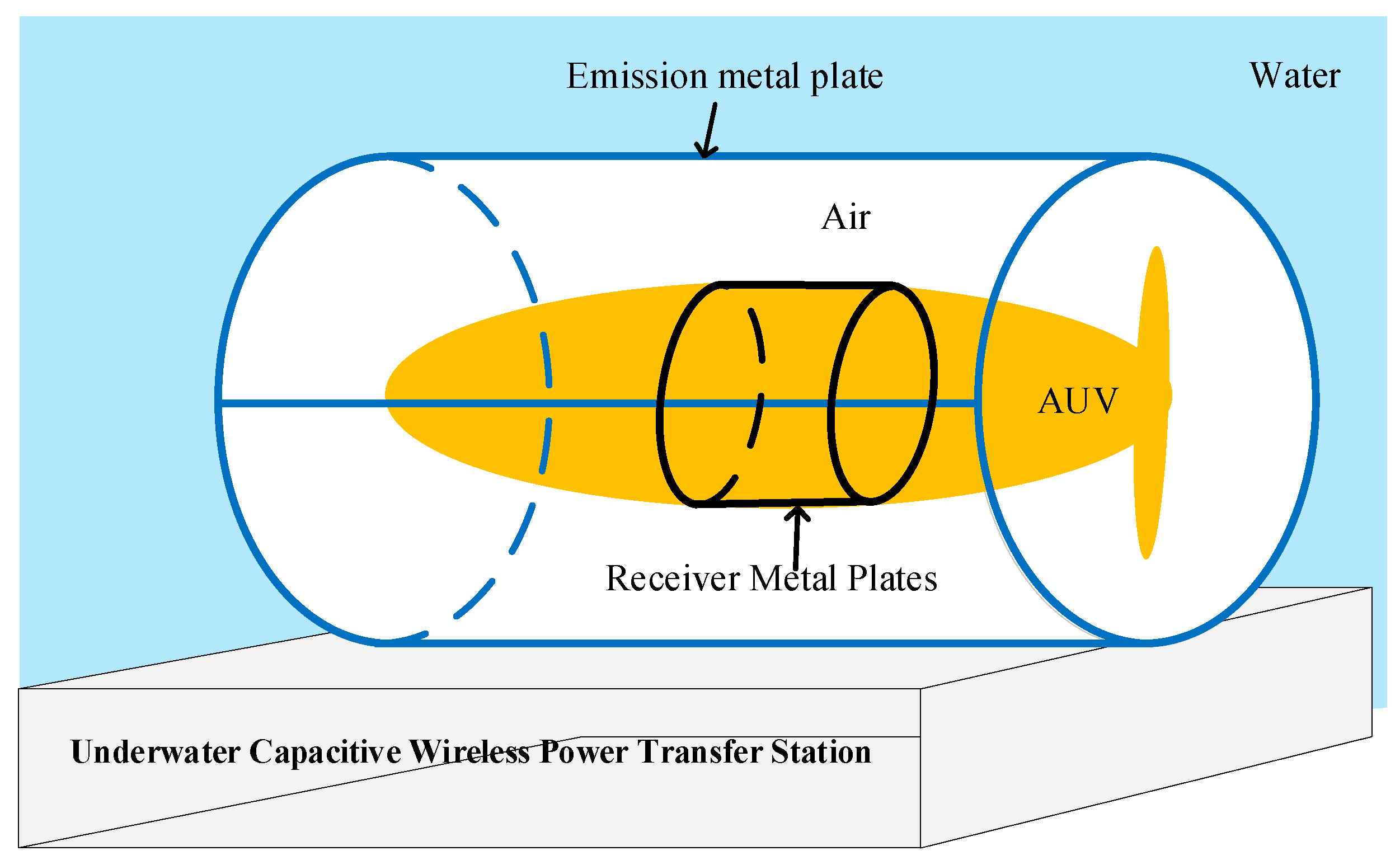
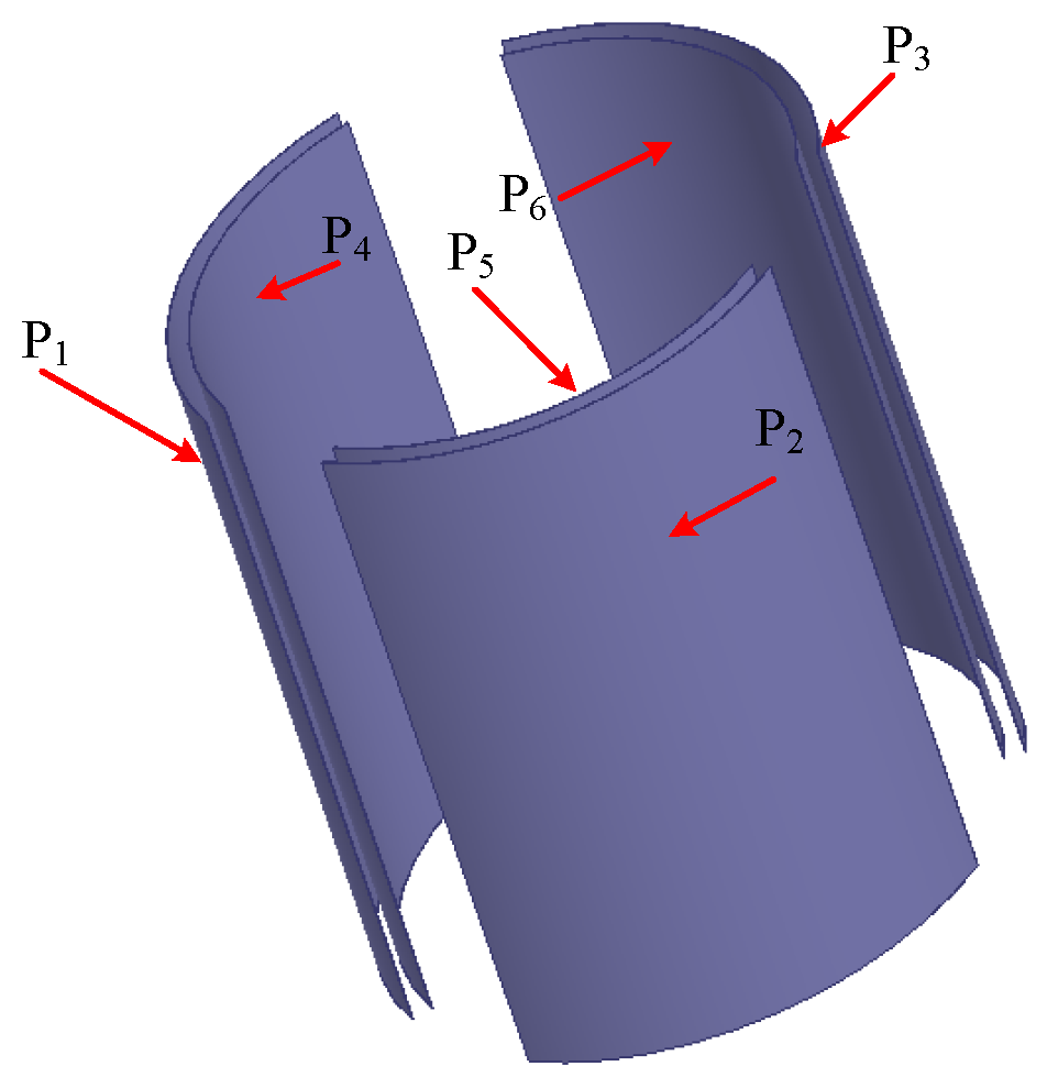
As shown in
Figure 1, the transmitter coupling structure consists of three curved metal plates, each forming a 100-degree arc. Correspondingly, the receiver coupling structure incorporates three symmetrically designed 100-degree arc-shaped metal plates. As a result, the power can be wirelessly transferred through the three curved metal coupling structure. The battery of AUVs could be charged between the transmitter metal coupling structure and receiver metal coupling structure.
The topology of the multi-phase column underwater capacitive WPT system is shown in
Figure 2. On the primary side, a three-phase inverter converts the DC voltage. An LCLC-LCLC compensation network is used to keep the system resonant. Power is transmitted via a multi-phase metallic plate capacitive coupling structure based on a high-frequency alternating electric field. On the secondary side, a full-bridge rectifier converts the high-frequency AC voltage. The output voltage and current are regulated by a controlled DC-DC converter to charge the underwater robot. Three receiver plates (with 100-degree arc) are placed inside the autonomous submersible. Three transmitter plates (100-degree arc) form a cylindrical charging dock. This enables stable wireless charging in dynamic underwater environments.
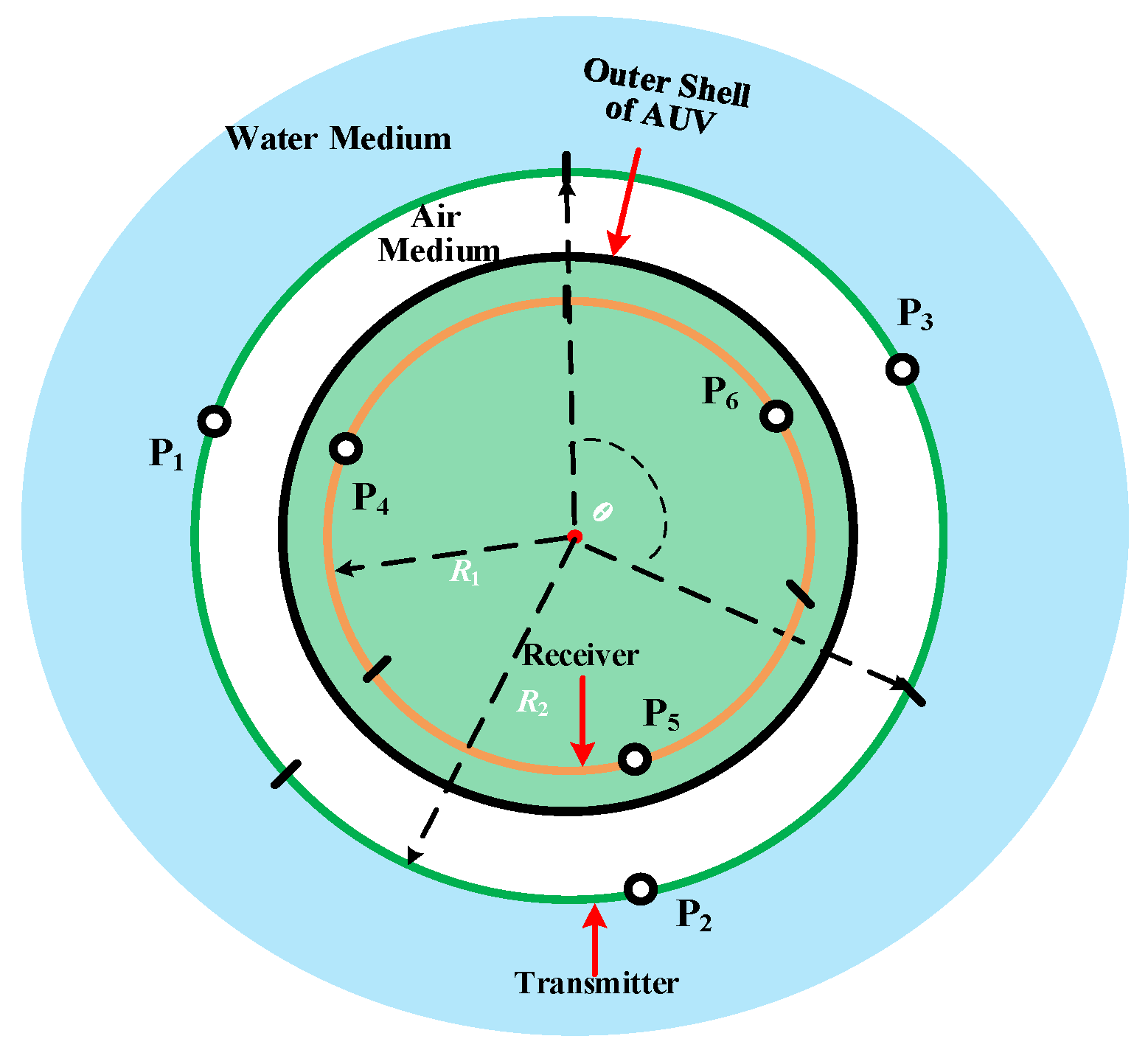
The capacitive coupling structure of the UCWPT system is shown in
Figure 3. It can be seen from
Figure 3 that the three-column receiving plates could build a cylindrical receiver mechanism. It will be placed inside the AUVs, which is close to the outer shell. The three-column transmitting plates could also build a larger cylindrical transmitter mechanism with a bigger diameter. As a result, the column capacitive coupling structure is constructed. It could both work in the undersea condition and the air condition. The power could be transferred through the outer shell of AUVs.
The theory analysis and the calculation are conducted in the following parts.
With the seawater medium, the dielectric constant of seawater determines the coupling capacitance. The relationship between the dielectric constant of seawater, seawater temperature, seawater salinity, and the angular frequency of electromagnetic wave is as follows:
where
ε∞(
S,
T) is the dielectric constant of seawater at infinite frequency,
ε0 is the dielectric constant of free space,
ω = 2π
f,
f is the frequency of electromagnetic wave,
εS(
S,
T) is the static dielectric constant of seawater,
δ(
S,T) is the ionic conductivity of seawater, and
τ(
S,
T) is Debye relaxation time.
The coupling capacitance
CM of the coupling mechanism based on the arc metal plate can be expressed as follows:
where
ε0 is the dielectric constant of the dielectric between plates,
a,
b, and
c are the semi-major axis, semi-minor axis, and semi-focal length of the elliptic cylinder belonging to the curved plate, and
α is the central angle of the curved metal plate.
If the curved metal plate could be transformed into a symmetrical circular column capacitor, where
a =
b and
c = 0, the coupling capacitor
CM can be expressed as follows:
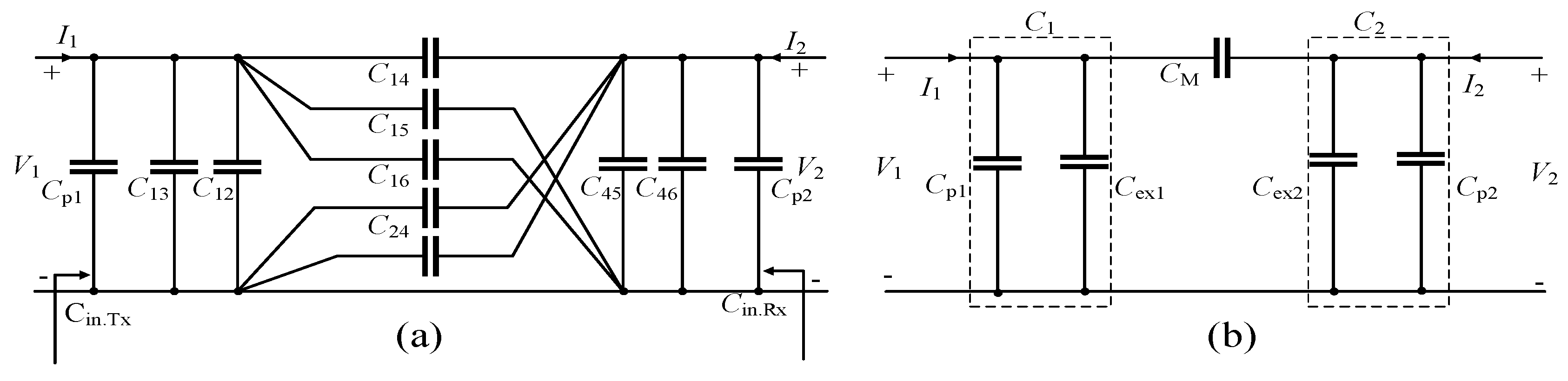
In the three-phase six-plate coupling structure, there is coupling between the two plates.
Figure 4 shows all the coupling capacitors between the six plates (three coupling structure).
C14,
C25, and
C36 are mutual capacitors for energy transfer between the primary and secondary sides,
C12,
C23, and
C13 are the self-capacitance between the primary side three-phase plates, and
C45,
C56, and
C46 are the self-capacitance between the secondary side three-phase plates. The remaining capacitors will also have an effect on the capacitance of each phase.
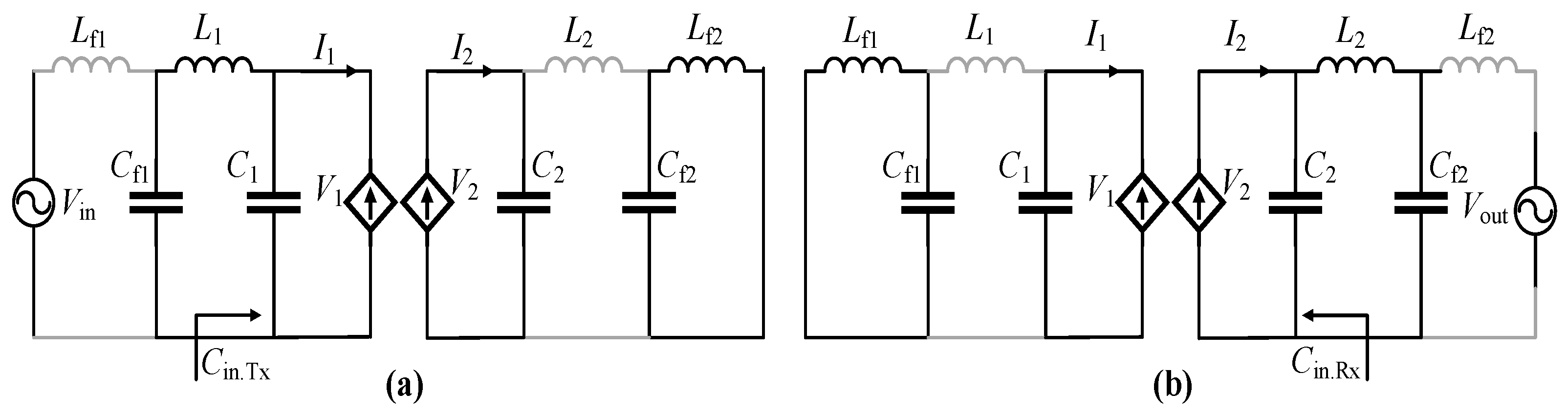
The circuit topology and coupling mechanism of the three-phase CPT system are symmetric. As a result, the three-phase system can be simplified to a single-phase system for analysis. The simplified equivalent circuit of the single-phase coupling mechanism is shown in
Figure 5a. For convenience of analysis, the circuit shown in
Figure 5a is simplified into a network of the type shown in
Figure 5b.
3. Theory Analysis of Underwater Capacitive Wireless Power Transfer Method
As shown in
Figure 5a, the A-phase input–output voltage is defined as
V1, and
V2. The input–output current is defined as
I1 and
I2,. The coupling mechanism is regarded as A two-port network, then the input–output relationship is shown as follows:
Similarly, the input–output relationship of the circuit model shown in
Figure 5b could be expressed as follows:
The two models (
Figure 5a,b) are equivalent to each other. Therefore, the equivalent parameter can be obtained by combining Equations (4) and (5):
The
Cp1 and
Cp2 is the compensation capacitor,
Cp1 and
Cex1 are connected in parallel, and
Cp2 and
Cex2 are connected in parallel.
The
Cin.Tx and
Cin.Rx is the compensation capacitor,
Cp1 and
Cp2 are connected in parallel, and
Cp1 and
Cp2 are connected in parallel,
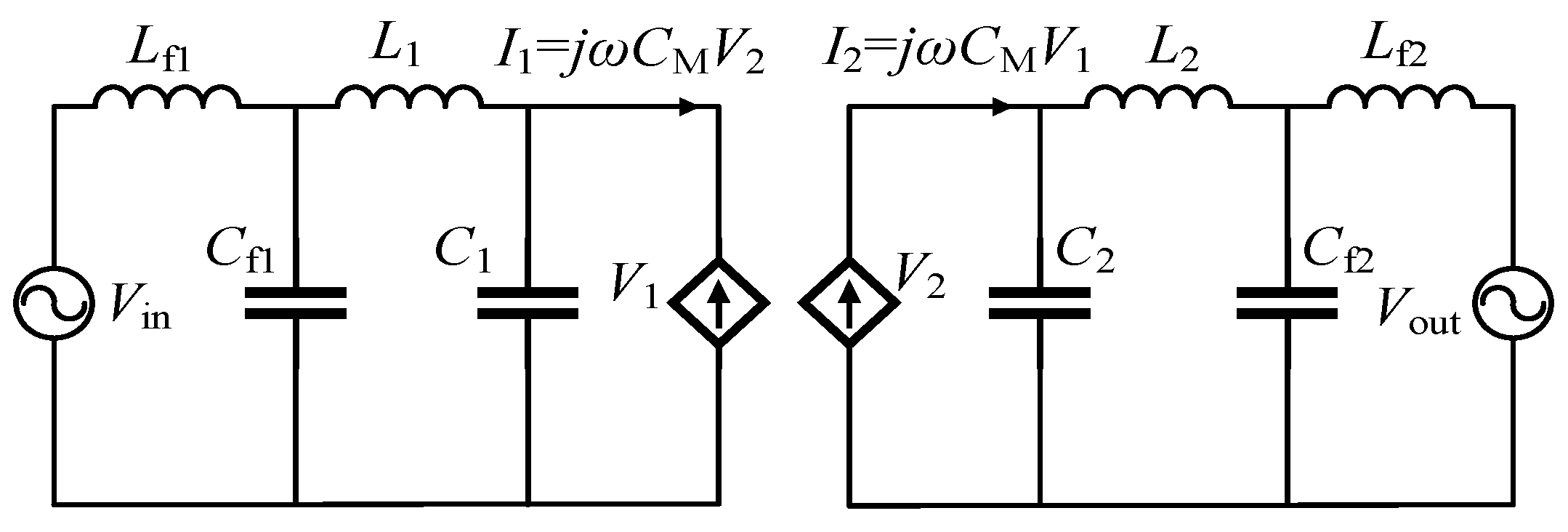
The Fundamental Harmonic Approximation is adopted to simplify the circuit, and the circuit is analyzed by superposition theorem. As shown in
Figure 6, this approach yields a simplified circuit model for phase A of the three-phase CWPT system. The input and output voltages are represented by two AC voltage sources. The superposition theorem is used to analyze the resonant circuit separately when the input and output voltages are used as excitation.
Figure 7a shows that the resonant circuit is excited only by the input voltage. In this case,
Lf2 and
Cf2 form a parallel resonance, the impedance is infinite, and
L2 is regarded as an open circuit.
L1,
Cf1, and
Cin.Tx form another parallel resonance, and no current flows on
Lf1. Therefore, the relationship between circuit parameters is expressed as follows:
Since
Lf1 and
L2 are considered as the open circuit. As a result,
Vcf1 =
Vin and
Vcf2 =
V2. According to
Figure 7a, the following equations could be derived as follows:
The output power could be represented as follows:
Figure 7b shows that the resonant circuit is excited only by the output voltage. Where
Lf1 and
Cf1 form a parallel resonance.
L2,
Cf2, and
Cin.Rx form another parallel resonance.
L1 and
Lf1 are regarded as an open circuit. There are no current that flow on
Lf1. The relationship between the related circuit parameters is expressed as follows:
As
L1 and
Lf2 are open circuits,
Vcf1 =
V1 and
Vcf2 =
Vout. According to
Figure 7b, the calculation of the parameters could be obtained as follows:
The input power could be derived as follows:
As can be seen from Equations (10) and (13), the output current (−ILf2) is leading the input voltage, Vin, by 90°, and the input current is lagging the output voltage, Vout, by 90°. Since an uncontrolled diode rectifier is used at the secondary side, the output voltage, Vout, must be in phase with the output current (−ILf2). Therefore, the input voltage, Vin, is in phase with the input current, ILf1.
The phase difference,
θ, between the emitter-side voltage,
V1, and the receiver-side voltage,
V2, of the electric field coupling mechanism can be expressed as follows:
4. Simulated and Experimental Verification for Underwater Capacitive Wireless Power Transfer System
The 3D model of the cylindrical coupling mechanism is shown in
Figure 8. Simulation is conducted with Ansys Maxwell 16.0 software, and the parameters of column six-plate capacitive coupling structure are shown in
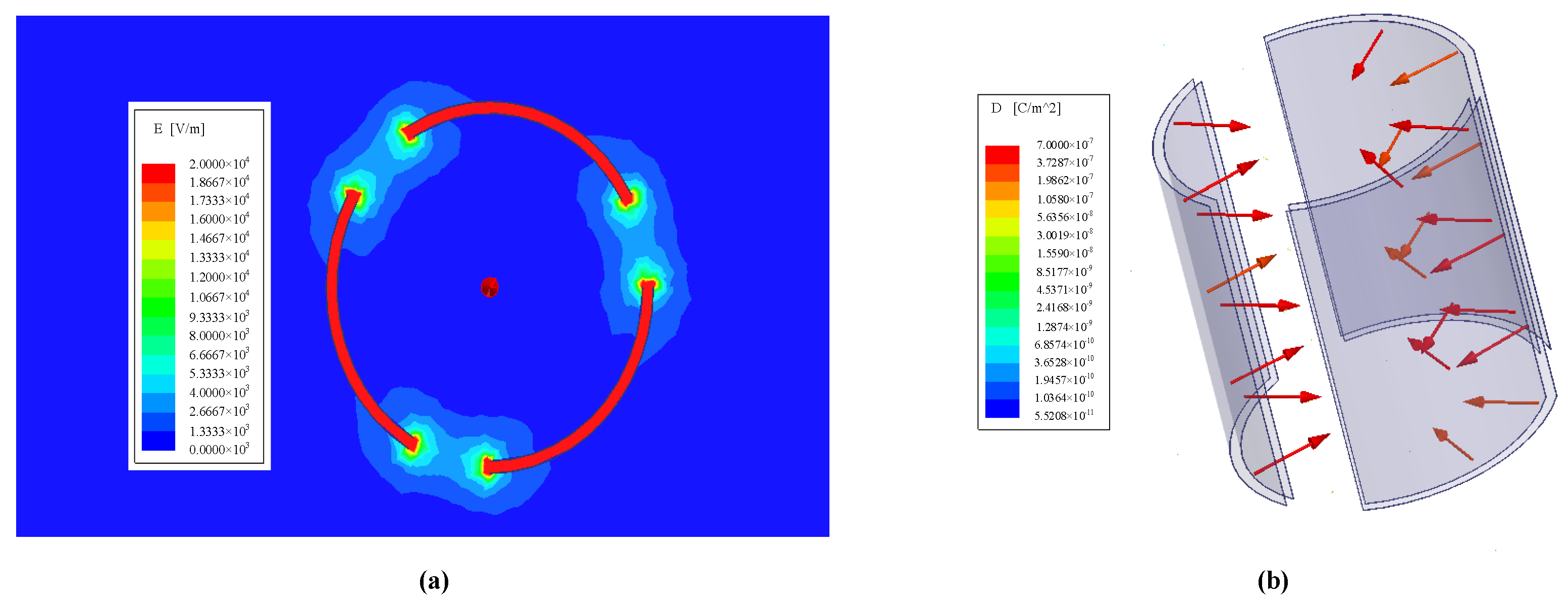
Table 1. The switching frequency is set at 500 kHz. The simulated results are shown in
Figure 9. The electric field intensity distribution is shown in
Figure 9a. It can be seen from
Figure 9a that the high electric field is generated. The highest electric field intensity is distributed between the transmitter plate and the receiver plate. The simulated current vector field distribution is shown in
Figure 9b. As shown in
Figure 9b, the current vector is distributed in the capacitive coupling structure. The power transfer capacity is verified. The column six-plate capacitive coupling structure could help to solve the charging voltage and current fluctuation caused by vehicle rolling in dynamic ocean environment.
Figure 10a,b illustrates the change in the coupling capacitance when the coupling plates are offset. According to the calculation formula of coupling capacitance, the coupling capacitance is related to the front of the coupling plate, and when the opposite area decreases, the coupling capacitance also decreases. As shown in
Figure 10a, when the coupling plates are rotationally offset, the facing area between them decreases, resulting in a decrease in electric field distribution between them and the coupling capacitance.
As shown in
Figure 10b, when the coupling plate is vertically offset, the opposite area between them decreases, resulting in a decrease in coupling capacitance. At the same time, it can be seen that the coupling capacitance decreases more obviously when vertical offset occurs.
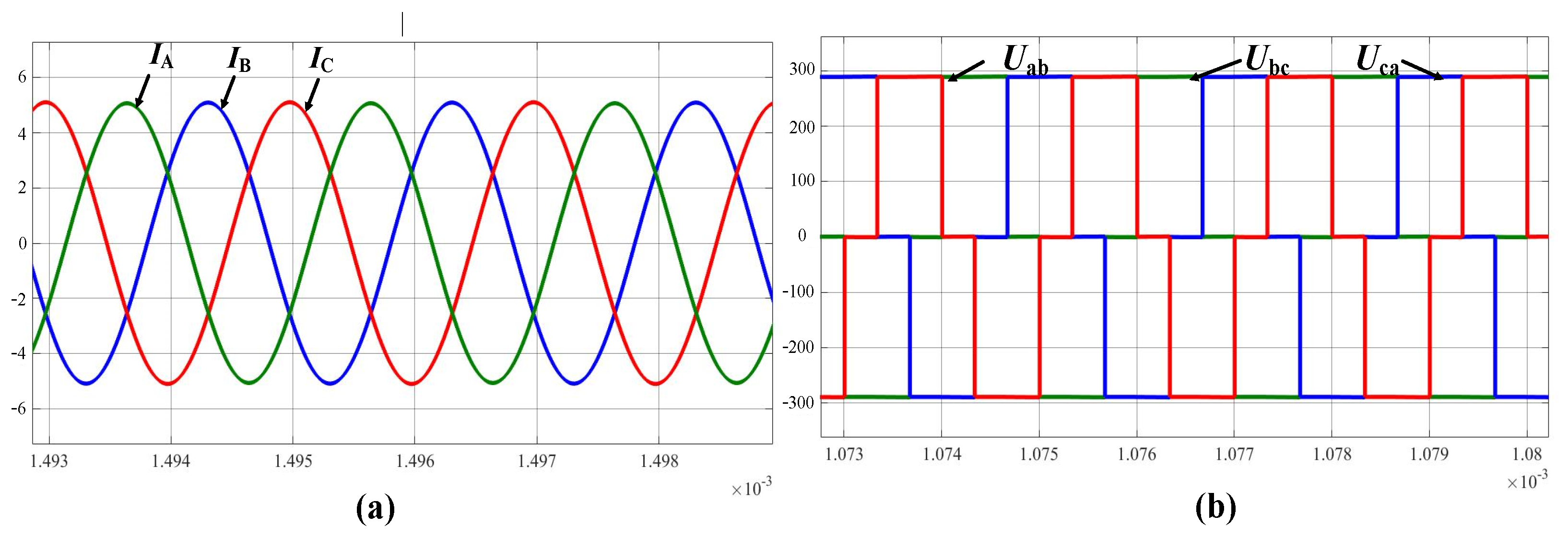
The UCWPT power circuit simulation is conducted with MATLAB/Simulink 2022a software. The parameters of the presented capacitive wireless power transfer system are shown in
Table 2.
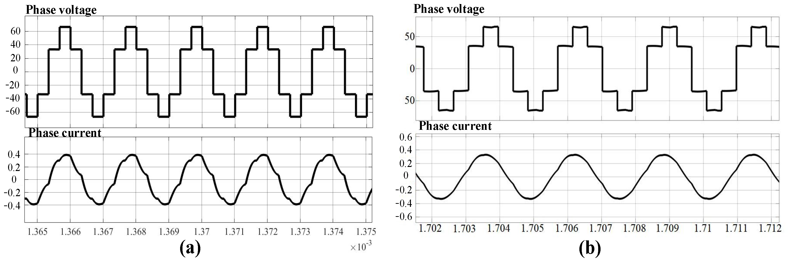
Figure 11a shows the current waveform of each phase output by the three-phase inverter under resonant state. The three-phase phase current amplitude is equal, and the phase difference between the currents of each phase is 120 degrees. The line voltage
Uab,
Ubc, and
Uca are all presented in
Figure 11b, and the phase-shift between those voltages is also 120°.
Figure 12a,b provide waveforms related to the phase current and voltage of the A-phase transmitter and receiver. As shown in the figure, the phase current,
IA, and the voltage,
UA, of the primary and secondary sides are in the same phase and can realize the zero phase angle, so that the system operates under the condition of complete resonance, thereby maximizing the active power transmission and reducing the energy loss. At the same time, we can see that the voltage gain is close to 1, which is also consistent with the realization results.
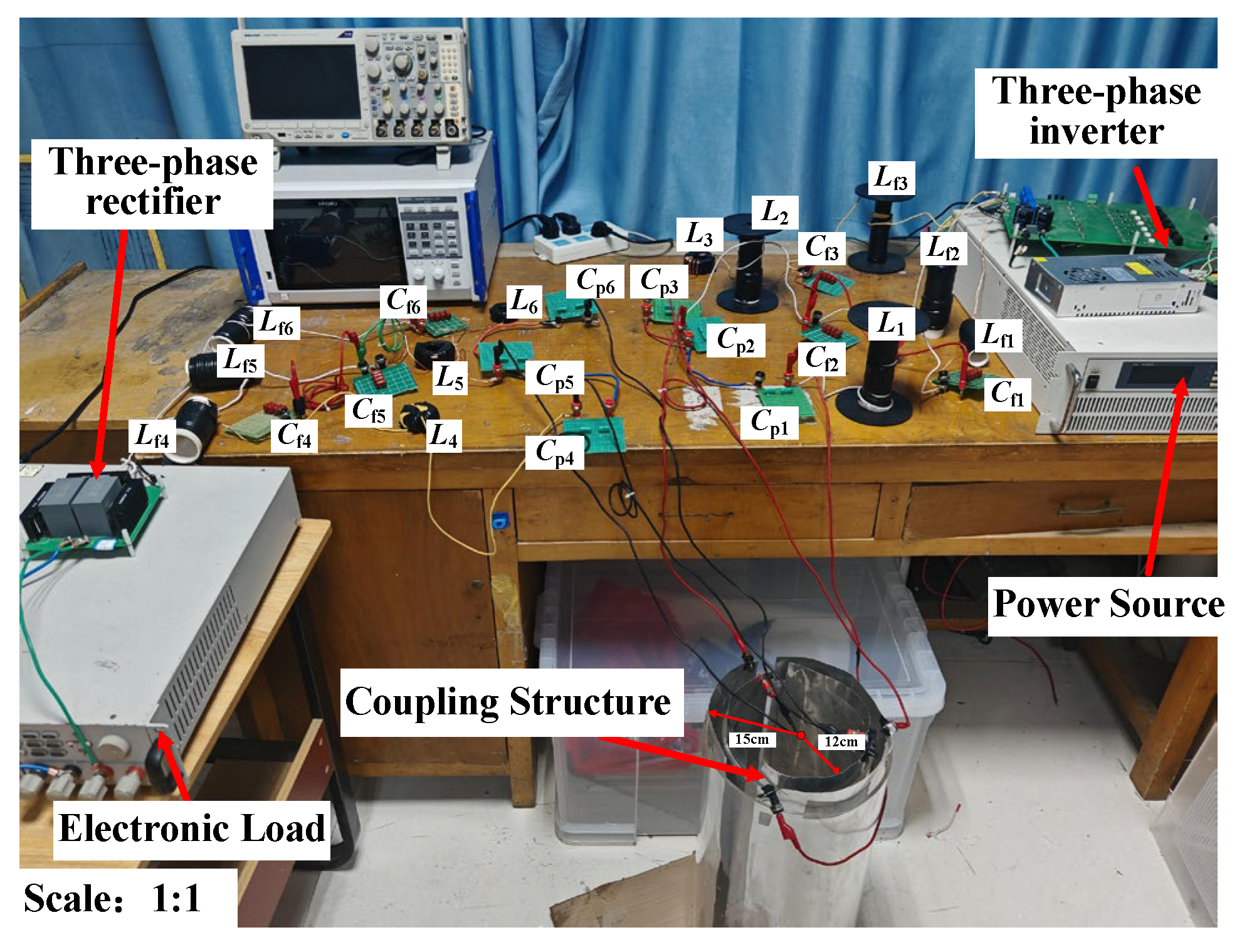
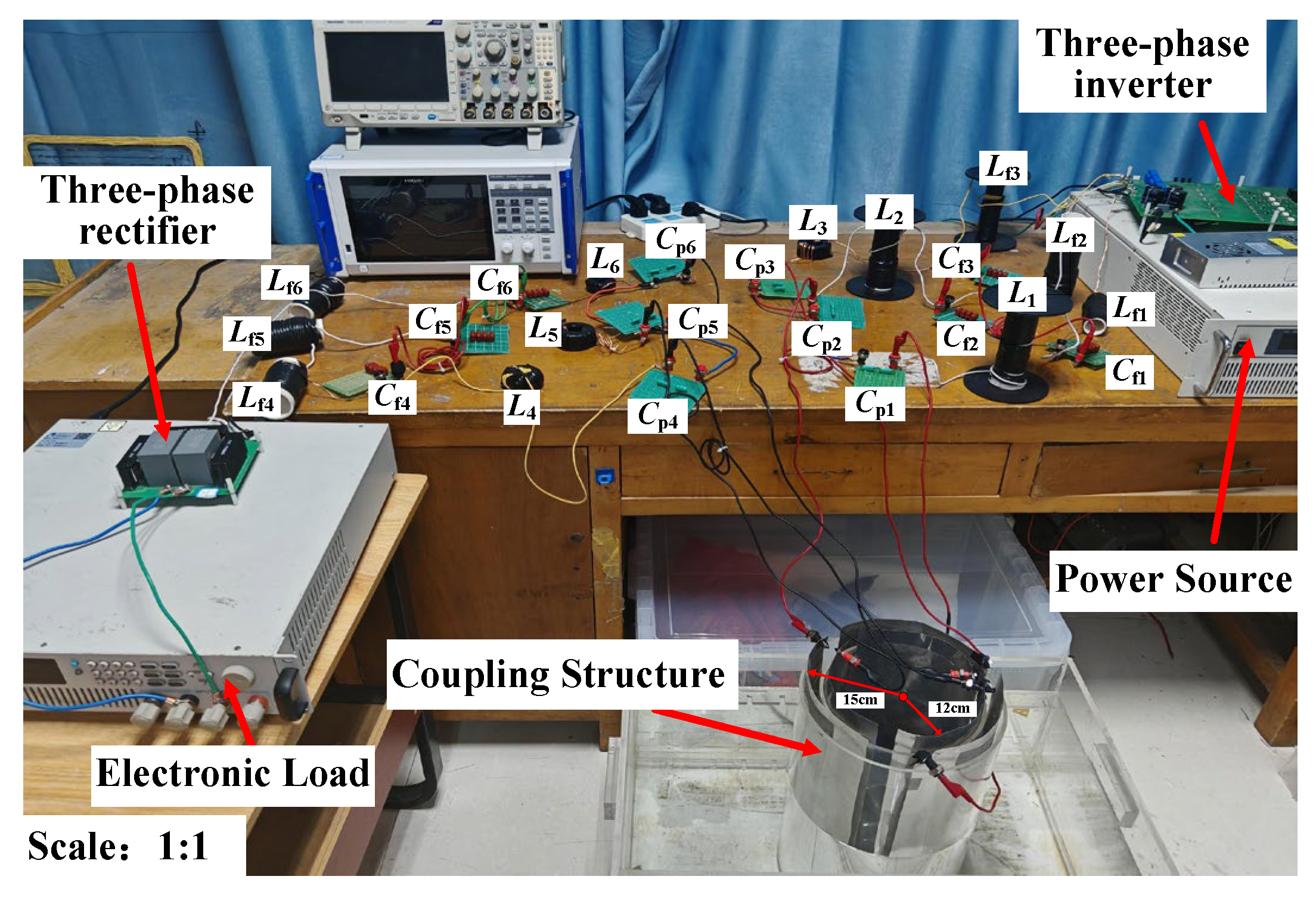
The experimental setup is shown as
Figure 13 with the column six-plate capacitive coupling structure. The system parameters are shown in
Table 2. The experiments are conducted in the air condition. The full bridge inverter circuit and full bridge rectifier circuit are used for inverting voltage and filtering voltage, respectively. The LCLC-LCLC compensation network is adopted in this paper. The three-column receiver metal plates (120° arc) is placed in AUVs to act as the receivers. The three-column transmitter metal plates (120° arc) build a cylindrical charging dock. The battery could be wirelessly charged through the high frequency alternating electric fields when the AUVs enter and stop in the cylindrical charging dock in the water environment. With the column capacitive coupling structure, the wireless charging could be conducted in a dynamic marine environment with ocean effects.
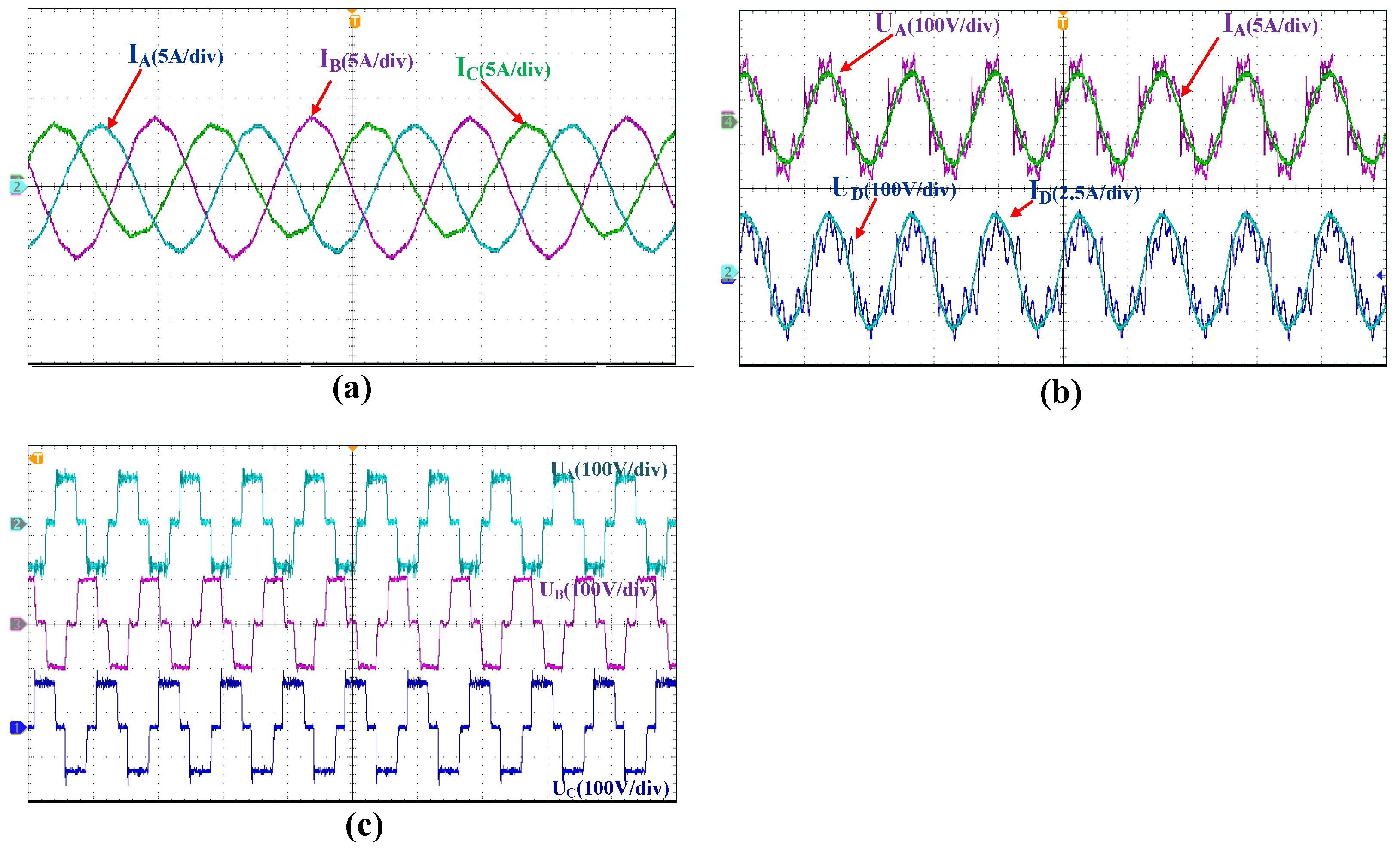
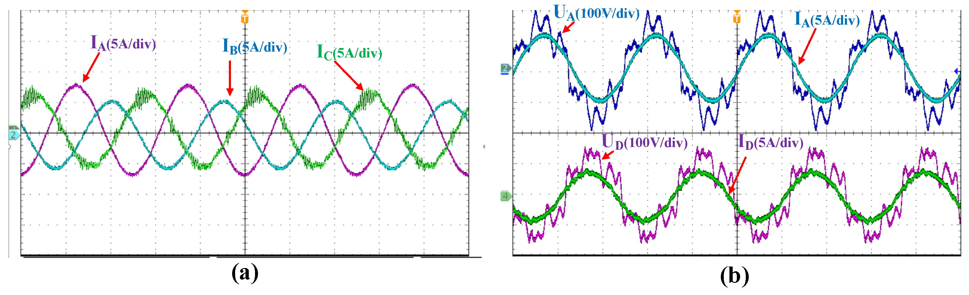
The experimental results of the capacitive wireless power transmission (CWPT) system in the air medium are shown in
Figure 14.
Figure 14a describes the phase current waveforms output by the three-phase inverter when the system works in a resonant state. As shown in the figure, the amplitudes of the three-phase phase currents are equal, and each phase current presents a phase difference of 120 relative to other phase currents.
Figure 14b shows the resonance relationship between primary and secondary phase voltages and phase currents.
UA and
IA are the primary phase voltage and phase current, and
UD and
ID are the secondary phase voltage and phase current. It can be seen that the primary and secondary phase voltages and phase currents are in the same phase, which shows that the system is in a resonant state, which is basically consistent with the simulation waveform.
Figure 14c shows the three-phase line voltage, each phase has the same amplitude, and there is a 120 phase difference between them. The experimental results show that the proposed CWPT system realizes the resonance state in air medium and the maximum wireless power transmission capacity of 800 W, and the peak efficiency is 80%.
The power analyzer is manufactured by HIOKI Company in Shanghai, China. The Mixed Domain Oscilloscope is produced by Tektronix Company in Shanghai, China. The load is produced by ITECH Company in Nanjing, China. The inverter, rectifier, coupling mechanism and compensation network are produced by the author team.
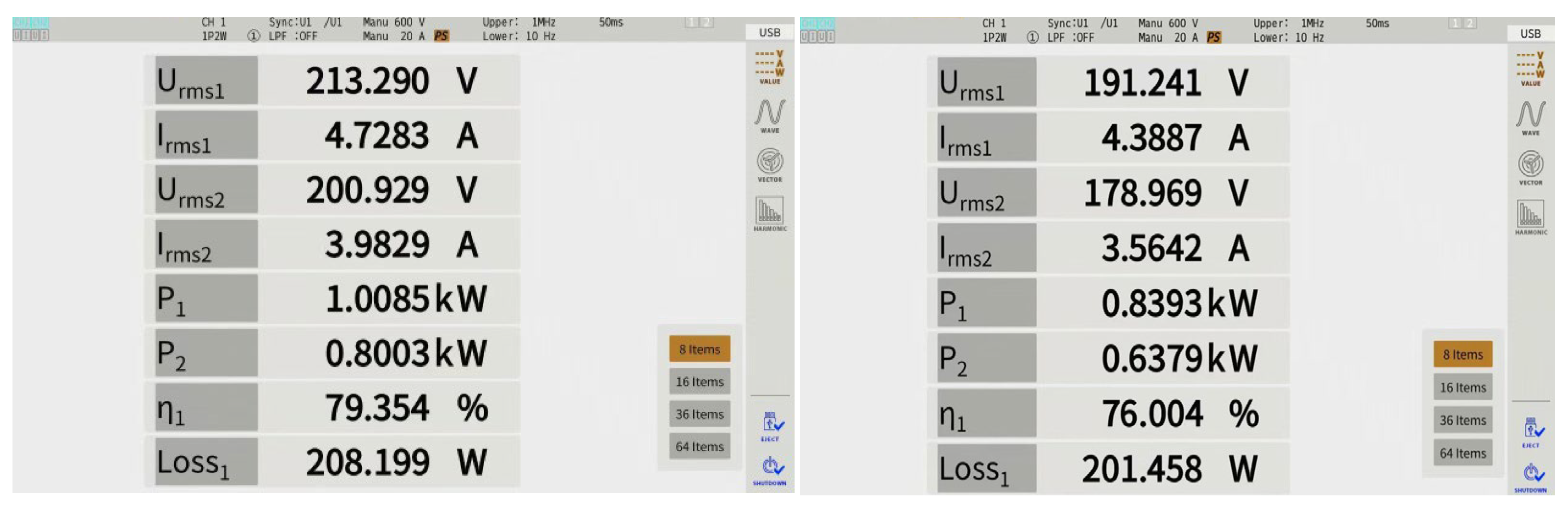
Figure 15 shows that the power efficiency of the system is 80% at 800 W underwater, and the transmission efficiency is 76% when it is close to 600 W.
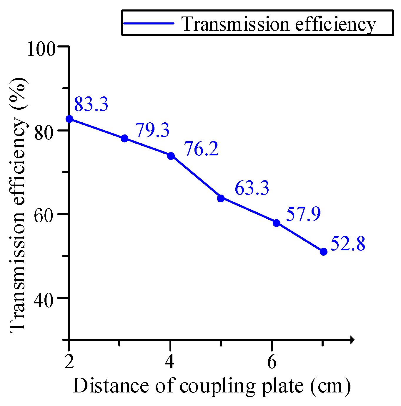
As shown in
Figure 16, the relationship between the distance between the coupling plates and the transmission efficiency shows that with the increase in the transmission distance, the transmission efficiency begins to decline slowly and then drops sharply.
When the vehicle enters the cylindrical charging pile, close the entrance, drain the water, and charge. The underwater test platform is shown in
Figure 17. The conductivity of seawater is 5.3 S/m, and the dielectric constant is 73.
The coupling mechanism is placed in seawater, and the experimental results are shown in
Figure 18.
Figure 18a describes the phase current waveform output by the three-phase inverter when the system works in a resonant state. As shown in the figure, the amplitudes of the three-phase phase currents are slightly different, and each phase current has a phase difference of 120 relative to other phase currents.
Figure 18b shows the resonant relationship between primary and secondary phase voltages and phase currents. Consistent with the experimental waveform in air,
UA and
IA are the primary phase voltage and phase current, and
UD and
ID are the secondary phase voltage and phase current. The primary and secondary phase voltages and phase currents are in phase, indicating that the system is in a resonant state. Therefore, the UCWPT system can operate normally in an underwater environment.
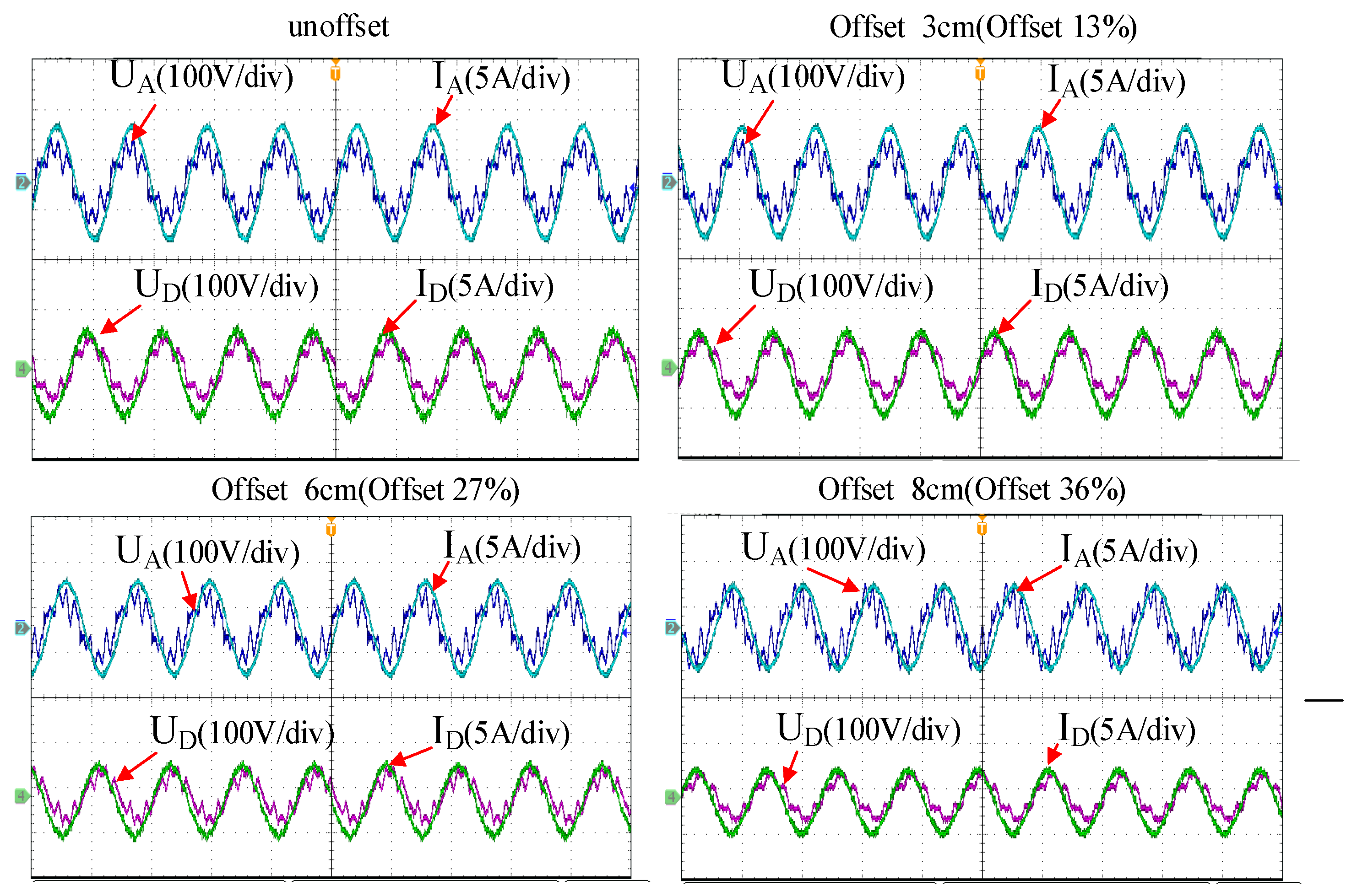
The barrel coupling structure has good anti-migration. The resonance waveforms of the system at different offset distances are shown in
Figure 19.
The single arc length of the coupling mechanism is 22 cm. As shown in
Figure 18, when the deviation is 3 cm, there is no obvious change. When the deviation is 6 cm, the voltage and current at the transmitter are slightly different; when the deviation is 8 cm, there is an obvious phase deviation between current and voltage. The results show that the coupling mechanism has good anti-drift performance.
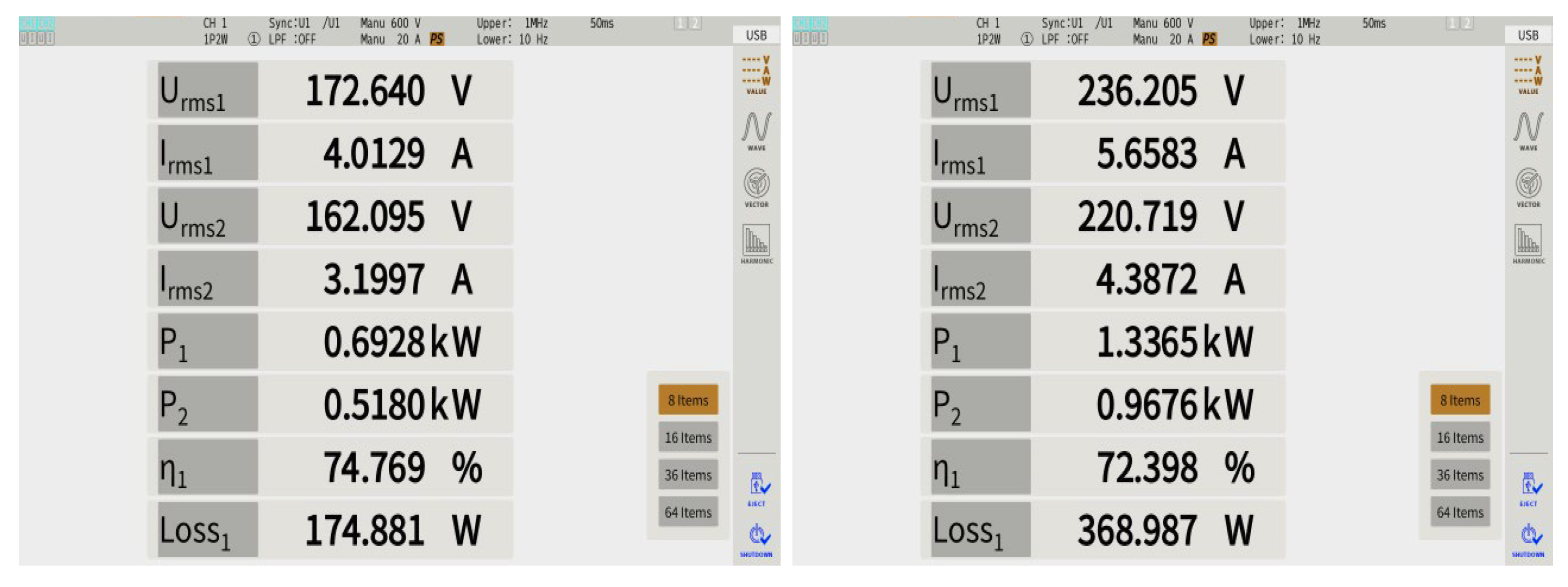
The experimental data of the UCWPT system in seawater medium are shown in
Figure 20. The power efficiency of the system is 74% at 500 W underwater, and the transmission efficiency is 72% when it is close to 1000 W.
The maximum power in the air of wireless power transmission system is 800 W, and the maximum efficiency is 80%. The maximum power in seawater environment is 1000 W, and the maximum efficiency is 74%. When the load is set to 50 Ω, the peak efficiency of 80% can be achieved. The results show that the experimental results are in good agreement with the theoretical analysis, and simulation results of good performance verify the superiority of the system.


 ,
, 


