Article

A Saturation Adaptive Nonlinear Integral Sliding Mode Controller for Ship Permanent Magnet Propulsion Motors

Guangdong Provincial Key Laboratory of Intelligent Equipment for South China Sea Marine Ranching, Guangdong Ocean University, Zhanjiang 524088, China
*
Author to whom correspondence should be addressed.
J. Mar. Sci. Eng. 2025, 13(5), 976; https://doi.org/10.3390/jmse13050976 (registering DOI)
Submission received: 11 April 2025 / Revised: 13 May 2025 / Accepted: 14 May 2025 / Published: 18 May 2025
(This article belongs to the Section Ocean Engineering)

Abstract

:
The conventional-speed Sliding Mode Controller (SMC) for ship PM propulsion motors, which employs exponential reaching laws and linear sliding surface functions, demonstrates susceptibility to oscillatory phenomena. To solve this problem, this paper proposes a saturation adaptive nonlinear integral sliding mode controller (SANI-SMC) which combines a nonlinear integral sliding surface function with an adaptive saturation gain reaching rate. The nonlinear integral sliding surface function improves the system responsiveness, and then enhances the stability and robustness of the system. The adaptive saturation gain reaching rate not only mitigates the chattering effect induced by the sign function in traditional exponential reaching rates, but also weakens the underlying oscillations. This approach effectively solves the overshoot problem inherent in traditional PI controllers, and has better anti-interference ability under sudden load variations. Finally, the proposed controller is experimentally verified based on an electric propulsion semi-physical experimental platform consisting of Rapid Control Prototyping (RCP), and compared with a Proportional–Integral (PI) controller and an SMC. Moreover, the integral absolute error (IAE), integral time-weighted absolute error (ITAE), and integral of the square value (ISV) metrics are calculated for the PI controller, SMC, and SANI-SMC based on experimental data collection. The results demonstrate that the SANI-SMC exhibits superior stability and robustness compared to both the PI controller and SMC.

1. Introduction

Permanent magnet synchronous motors (PMSMs) have undergone extensive adoption in electric vehicles, rail transit, and marine propulsion systems owing to their superior performance characteristics, such as high efficiency, exceptional power density, and remarkable overload capabilities [1,2,3,4]. However, controlling PMSMs poses significant challenges due to the inherent nonlinear dynamics, parameter variations, and strong electromagnetic coupling within the system, all of which degrade control precision. Under practical operating conditions, unpredictable disturbances, including parameter uncertainties, exogenous load fluctuations, and unmodeled dynamics, can severely compromise the robustness of conventional control architectures. Traditional PI controllers, while widely implemented, struggle to effectively mitigate these disturbances and are therefore ill suited for high-precision motion control scenarios [5,6,7,8]. In contrast, sliding mode control has emerged as a robust control strategy, leveraging its intrinsic insensitivity to parameter deviations and external perturbations to ensure stability under dynamic operating regimes [9].
Various approaches have been proposed to enhance the speed control performance of permanent magnet synchronous motor (PMSM) systems under different disturbances and uncertainties. It has been demonstrated that the application of nonlinear sliding mode surfaces can improve the dynamic response of a closed-loop system [10,11,12]. Several studies have employed linear sliding mode controllers (SMCs) for PMSM speed control; nonetheless, these studies acknowledge several limitations.
In recent years, some studies have enhanced sliding mode control performance by optimizing the control strategy, including modifications to the reaching law, improvements in the sliding surface function, and the incorporation of adjustable parameters [13,14,15,16,17,18]. Elmas et al. [19] introduced a nonlinear speed control algorithm for PMSM servo systems, integrating AN SMC and disturbance compensation techniques based on the sliding mode reaching law (SMRL). The approach dynamically adapts to system variations, ensuring high tracking performance while significantly reducing system chattering. Nonetheless, its performance may be compromised under complex environments or sudden external disturbances. Chang et al. [20] proposed a novel non-singular terminal sliding mode (NNTSM) control scheme, which utilized an expanded observer and a tracking differentiator to reduce noise and disturbances in the system. Although it enables the system to achieve zero overshoot, the mathematical model is complex, and the introduced observer and tracking differentiator are sensitive to variations in system parameters. Li et al. [21] proposed an integral sliding mode control (ISMC) strategy and examined the active reliable control problem for second-order nonlinear uncertain systems. This method not only enhances the dynamic response but also improves the tracking performance of the system. Song et al. [22] demonstrated that ISMC offers high robustness in terms of system overshoot, response speed, and steady-state error. When subjected to load disturbances, ISMC results in a smaller speed reduction compared to the PI controller. Nonetheless, the efficacy of the sliding mode controller is contingent upon the design of the switching surface and the selection of switching gains. In practical applications, suboptimal parameter choices can result in system instability or inadequate responses. Moreover, the parameter selection method discussed herein is relatively simplistic and may not encompass all real-world scenarios.
To mitigate issues such as high-frequency oscillations, uncertainties in dynamic models, and inadequate robustness under varying load conditions, this paper introduces a novel saturated exponential reaching rate combined with adaptive gains. The proposed nonlinear integral sliding surface function replaces the conventional linear sliding surface function, enabling the design of the saturation adaptive nonlinear integral sliding mode controller (SANI-SMC). The proposed controller enhances the integral term of ISMC while incorporating an adaptive reaching law. It maintains the system’s high robustness, ensuring minimal overshoot, a fast response speed, and a low steady-state error. Meanwhile, the adaptive component effectively mitigates load-induced fluctuations, significantly enhancing the system’s disturbance rejection capability. This successfully addresses the weak anti-disturbance performance of SMRL and substantially improves system stability. Finally, experimental validation is conducted using a semi-physical experimental platform. The results demonstrate that the proposed SANI-SMC method is both efficient and reliable. In summary, the key contributions of this work are as follows:
(1)
Enhanced Sliding Mode Control Design:
  • It proposes a nonlinear sliding mode surface function combined with an adaptive saturation-index reaching law.
  • It effectively suppresses control chattering while improving the response speed of traditional SMCs.
  • It incorporates adaptive mechanisms to enhance load variation robustness, significantly reducing load disturbance impacts.
(2)
Experimental Validation:
  • It demonstrates the SANI-SMC’s effectiveness through the experimental platform for ship electric propulsion.
  • It verifies the SANI-SMC’s superior performance over conventional PI controllers and SMCs in precision speed tracking, disturbance rejection capability, and overall system stability.

2. Mathematical Modeling of PMSM Electric Propulsion System

2.1. PMSM Model

For the surface-mounted PMSM, the permanent magnets are externally placed on the rotor, which results in a uniform distribution of magnetic flux density within the air gap. This configuration significantly increases the performance and operational efficiency of the motor. Consequently, this paper studies the surface-mounted PMSM. A two-phase rotating d-q coordinate system is employed to simplify the mathematical model of the PMSM.
By neglecting the stator core saturation, eddy currents, and hysteresis losses, the mathematical model of the surface-mounted PMSM in the two-phase rotating coordinate system can be expressed as [23]
u d = R s i d + L s d i d d t L s ω m P n i q u q = R s i q + L s d i q d t + L s ω m P n i d + ω m P n φ f J d ω m d t = 3 2 P n φ f i q T L B ω m
where ud and uq respectively, represent the voltages along the d and q axes, id and iq denote the currents along these axes, ϕ m denotes the magnetic flux linkage of the permanent magnet, ω m represents the mechanical angular velocity of the motor, J denotes the moment of inertia, Rs denotes the stator resistance, Ls denotes the stator inductance, TL represents the load torque, Pn denotes the number of pole pairs of the motor, and B is the damping coefficient.
The employed id = 0 vector control strategy facilitates the derivation of the relationship between the rotor speed and current, which can be written as:
d i q d t = 1 L s ( R s i q P n ω m φ f + u d ) d ω m d t = 1 J ( T l + 3 P n φ f i q 2 B ω m )

2.2. Novel Adaptive Gain Saturation Exponential Approaching Rate

Based on the fundamental principles of sliding mode control theory, it is crucial to design a sliding mode reaching function to ensure that the system reaches the sliding mode surface within a finite time. The conventional reaching rates commonly use an exponential convergence rate, which is expressed as
s ˙ = ε sgn ( s ) q s
where ε represents the sliding mode gain, s denotes the sliding mode surface function, and q is the exponential term. Considering the impact of the sign function on the system oscillations, the original sign function sgn(s) is substituted with a saturation function sat(s) while preserving the exponential term. Furthermore, an adaptive gain k(s) is incorporated to increase the dynamic performance of the system through the design of the control rate [24].
A novel adaptive gain saturation-based exponential convergence rate ( s ˙ ) is then defined as
s ˙ = k ( s ) ( η 1 s + η 2 s a t ( s σ ) ) k ( s ) = k 0 + α 1 + β | s |
where k(s) denotes the adaptive gain, η 1 s represents the term proportional to the sliding mode state function s, and η 1 is the exponential approaching rate gain used to regulate the rate at which the system error decays.
By appropriately increasing η 1 , the convergence speed of the system near the sliding mode surface can be increased, while the amplitude of the oscillations is reduced. More precisely, its variation is linear. As a result, when s is large, the system rapidly approaches the sliding mode surface. Note that η 2 s a t s σ is the saturation function term, where the saturation function (sat) is employed to limit the magnitude of the control input. This ensures that when s approaches the sliding mode surface, smooth convergence of the control of the system can be achieved, which allows the model to prevent the excessive control input from inducing system oscillations.
η 2 is the saturation approaching rate gain. When it increases, the system approach to the sliding mode surface from the outside is accelerated. However, a very large η 2 value may introduce significant chattering.
The s σ factor is used to adjust the control effort, where σ represents the threshold of the saturation function. An appropriate increase in σ allows the saturation function to exert its impact over a broader range, which reduces the chattering and increases the stability. However, σ should not be very large, as this could slow down the system response speed. k0 is the base gain, which regulates the overall approach speed of the system. α represents the adaptive adjustment magnitude, affecting the range of variation in the adaptive gain.
β is a parameter used to adjust the sensitivity of the adaptive gain to s , which affects the responsiveness of the gain to the changes in s . When s is large, the gain approaches k0, which results in a larger control gain. On the contrary, when s is small, the gain decreases, which reduces the oscillations. When s is large (much larger than the sliding mode surface), the gain k(s) is large, allowing the system to rapidly converge to the sliding mode surface. When s becomes smaller (near the sliding mode surface), k(s) decreases, which results in a reduction in the control effort and minimizes the oscillations; that is, η 1 > 0 , η 2 > 0 , σ > 0 , α > 0 , β > 0 , k ( s ) > 0 , k 0 > 0 .

2.3. Integral Nonlinear Sliding Mode Surface

The conventional linear sliding mode surface function is expressed as
s = c x 1 + x 2
where c is a design parameter, and x1 and x2 are the state variables. This paper defines s based on the conventional linear sliding mode surface function as
s = m c 1 e 1 d t + c 2 e 1 + e 2
where c1 and c2 are, respectively, the custom parameters for the integral and linear terms, and m is the sliding mode exponent.
By incorporating the integral term, the chattering phenomenon is significantly reduced, which results in an increase in the stability of the system.
The Lyapunov function [25] is used to validate the stability of the proposed algorithm:
V = 1 2 s 2
Differentiating Equation (7) and substituting it into Equation (4) yields
d V d t = s s ˙ = s ( k ( s ) ( η 1 s + η 2 s a t ( s σ ) ) )
Equation (8) yields
d V d t = k ( s ) ( η 1 s 2 + η 2 s s a t ( s σ ) )
For s > σ , the saturation function s a t s σ outputs sign(s), which has only two possible values: 1 or −1. Consequently, the approaching rate can be written as
d V d t = k ( s ) ( η 1 s 2 + η 2 | s | )
The expression is strictly negative definite, with η 1 s 2 + η 2 s and k(s) being positive. Therefore, the system always tends toward the sliding mode surface s = 0 , and d V d t < 0 .
For s σ , the saturation function s a t s σ becomes equal to s σ . Consequently, the approaching rate can be computed as
d V d t = k ( s ) ( η 1 s 2 + η 2 s 2 σ ) )
At this juncture, the condition d V d t 0 is satisfied. In summary, it is ensured that the trajectory of the system converges to the sliding mode surface in finite time.

3. Novel Sliding Mode Speed Control

3.1. Design of the SANI-SMC Controller

Based on Equation (2), the state variables of the PMSM electric propulsion are defined as
e 1 = ω r e f ω m e 2 = e ˙ 1 = ω ˙ m
The sets A and u are defined as follows: A = 3 P n ϕ f 2 J and u = i . This can be summarized as
u = 1 A [ m c 1 e 1 + c 2 e 2 B J e 2 + k ( s ) ( η 1 s + η 2 s a t ( s σ ) ) ]
Using Equation (13), the reference output current ( i q ) of the controller can be calculated as
i q = 1 A [ m c 1 e 1 + c 2 e 2 B J e 2 + k ( s ) ( η 1 s + η 2 s a t s σ ) ] d t
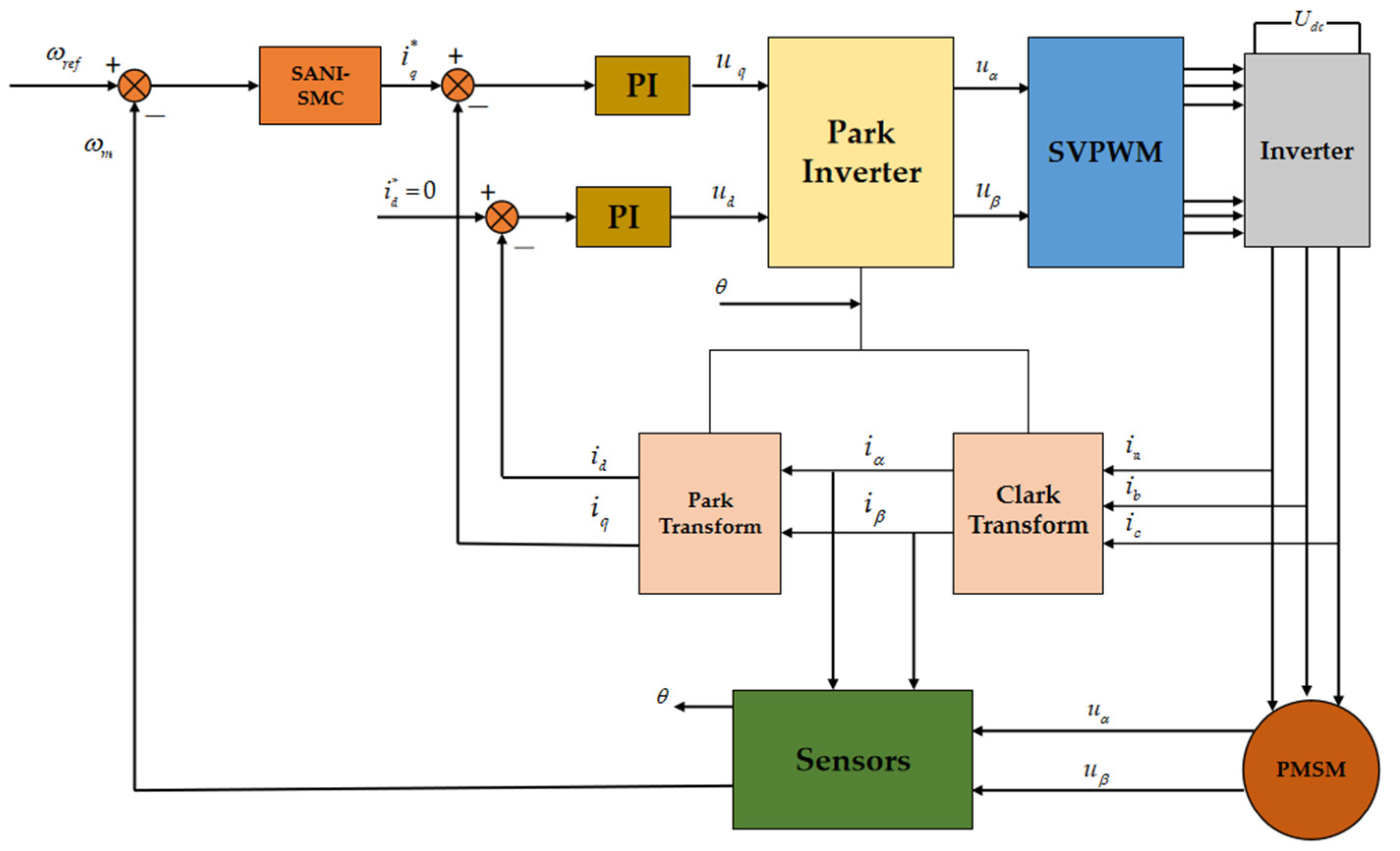
The final design of the SANI-SMC speed loop controller is illustrated in Figure 1.
Structure diagrams of the conventional PI speed loop controller and the traditional exponential sliding mode controller are shown in Figure 2.

3.2. Design of Novel Sliding Mode Control

The nonlinear novel sliding mode speed control for the ship PM propulsion motor is constructed based on the SANI-SMC, which is the double closed-loop vector control including the speed loop and the current loop control. Among them, the iq current is controlled by the SANI-SMC. The id* in the diagram represents the d-axis reference current. Finally, the control effect is achieved by regulating the current and voltage of the propulsion motor, as shown in Figure 3.

4. Experimental Verification of the Control Strategy

4.1. Experimental Setup

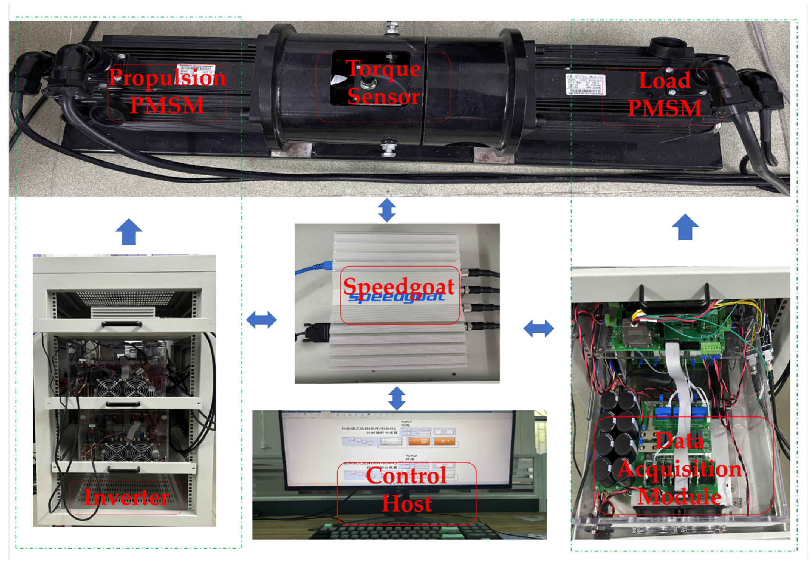
In order to evaluate the effectiveness of the novel sliding mode speed control, speed tracking and load disturbance experiments were conducted comparatively for the PI controller, SMC, and SANI-SMC based on the semi-physical electric propulsion platform. The experimental platform was mainly composed of a control host, a speed-goat real-time simulator, a propulsion PMSM, a load PMSM, and a control inverter, as shown in Figure 4. The arrows in the figure represent the control relationship between the components. The main parameters of the PMSM are presented in Table 1. To ensure the fairness of the comparative experiments, the impacts of the electromagnetic disturbances during motor startup were ignored. The speed-goat real-time simulator and PMSM were interactively controlled by the control converter. After turning on the equipment, the control signal generated by the PMSM was captured, and the relevant data were recorded and analyzed by the control host. Moreover, the SANI-SMC parameters could be adjusted online to optimize motor performance.

4.2. Comparison of Speed Tracking Performance for Three Controllers

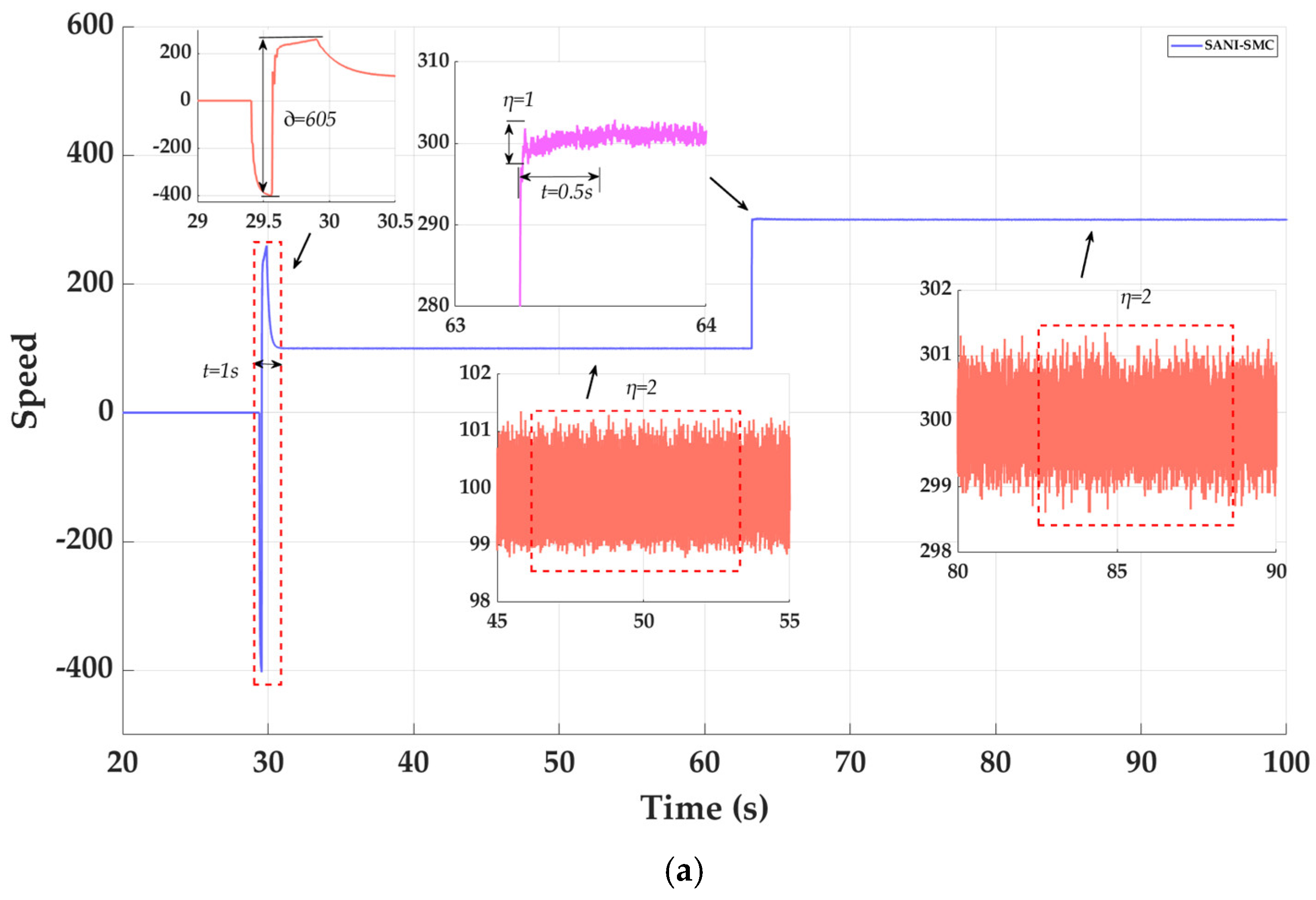
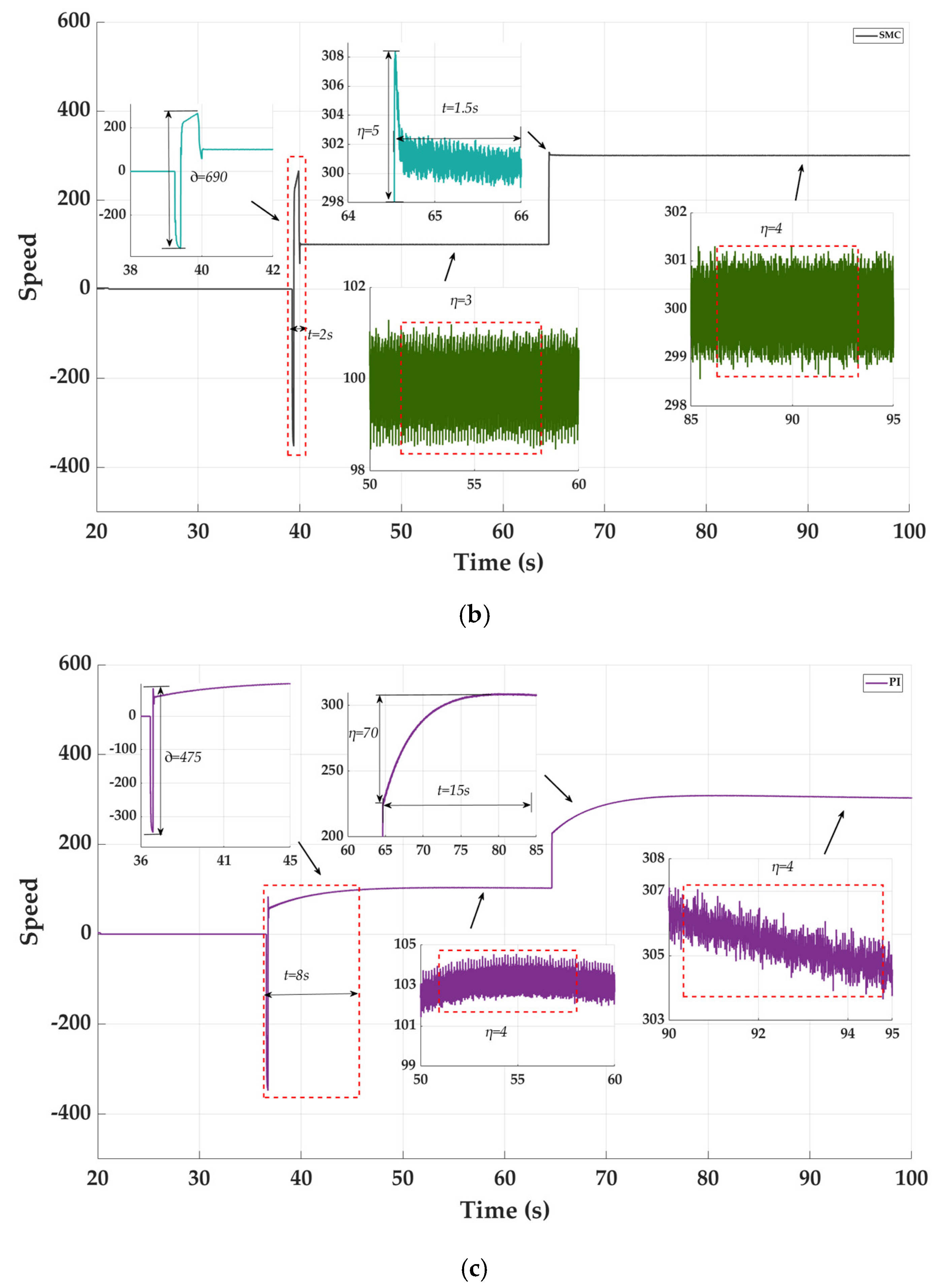
To evaluate the effectiveness of the SANI-SMC, the motor response speed, noise immunity, and anti-interference performance were compared under no-load conditions using the PI controller, SMC, and SANI-SMC. In the initial state, the speed was set to 100 rpm. It was then increased to 300 rpm after a period of stable operation. Figure 5 shows the dynamic response of the speed of the PMSM, and Figure 6 shows the variation in its three current functions of speed. The results of the comparison are shown in Table 2, where t represents the speed tracking time, represents the motor startup oscillation amplitude, and η represents the overshoot.
As can be clearly seen from Figure 5, the startup noise is small in the startup phase of the PMSM with the PI controller. However, the time to reach a stable speed is as long as 8 s, and the vibration after stabilization is significant. Although the SMC can shorten the startup time, the startup oscillation reaches 690 rpm, and the startup noise is significant. On the contrary, the SANI-SMC can significantly reduce the startup noise, which is reduced by 12.3% compared with that of the SMC, as shown in Table 2. Moreover, it shortens the time to reach a steady state, and reduces the vibration after reaching a steady state, which shortens the time from motor startup to steady state by 87.5% and 50% compared with the PI controller and SMC, respectively.
When the PMSM is in an acceleration state, the speed tracking time of the PI controller is as long as 15 s, and the speed overshoot reaches 70 rpm. The speed tracking time of the SMC is significantly reduced. However, the speed overshoot is equal to 5 rpm. The SANI-SMC has a shorter speed tracking time during acceleration, it only takes 0.5 s to reach the target speed, and its overshoot is only 1 rpm. Compared with the PI controller and SMC, the speed tracking time of the SANI-SMC is, respectively, reduced by 96.67% and 66.67% in the motor acceleration state, while the overshoot is reduced by 98.6% and 80%, respectively.
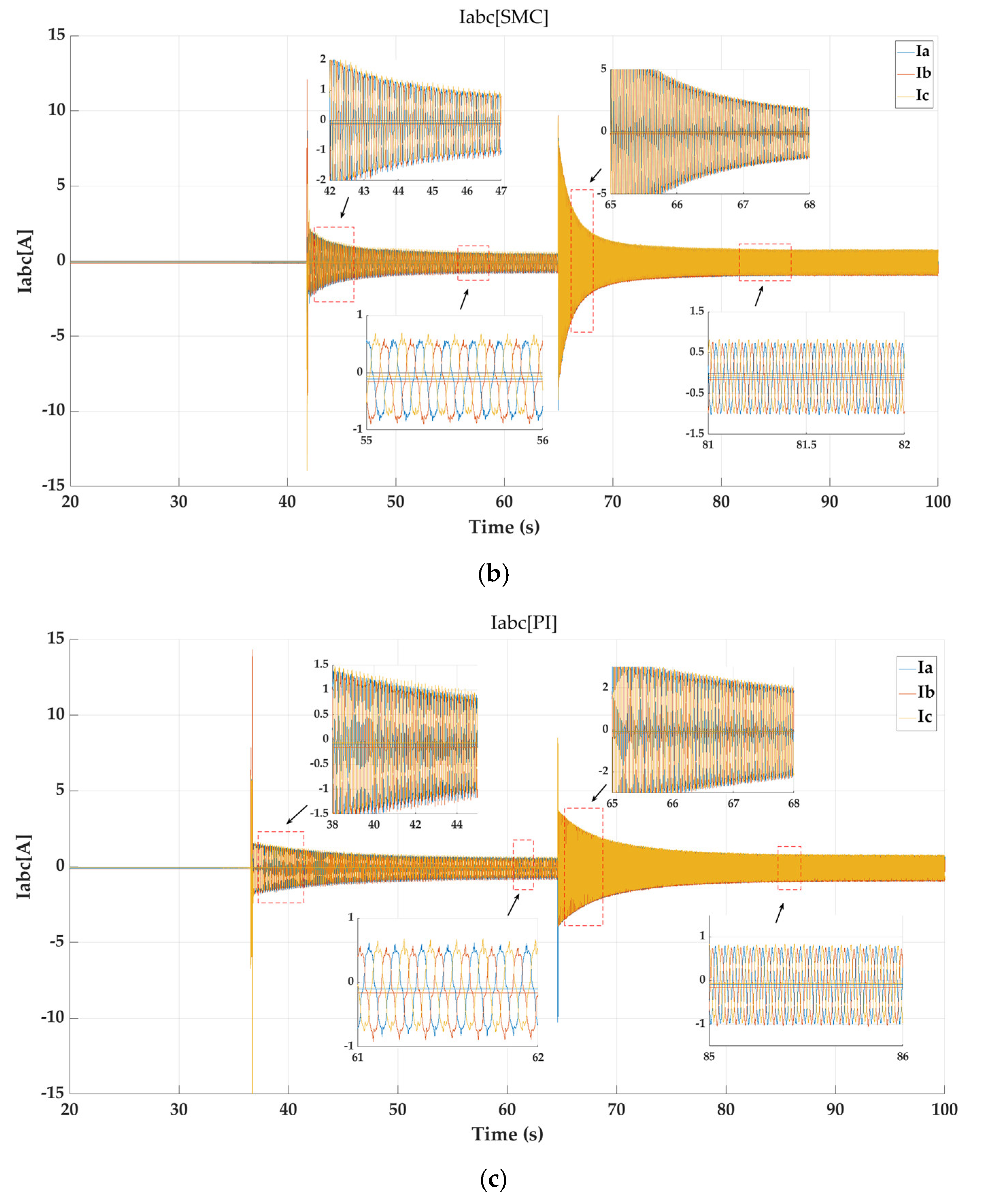
Figure 6 shows the variations in the three-phase current during motor operation. The current under the SANI-SMC exhibits the greatest stability, following a sinusoidal pattern and effectively suppressing internal interferences. The experimental results show that the comprehensive performance of the SANI-SMC is higher in the startup and acceleration stages of the PMSM.

4.3. Comparison of Loading Experiments for Three Controllers

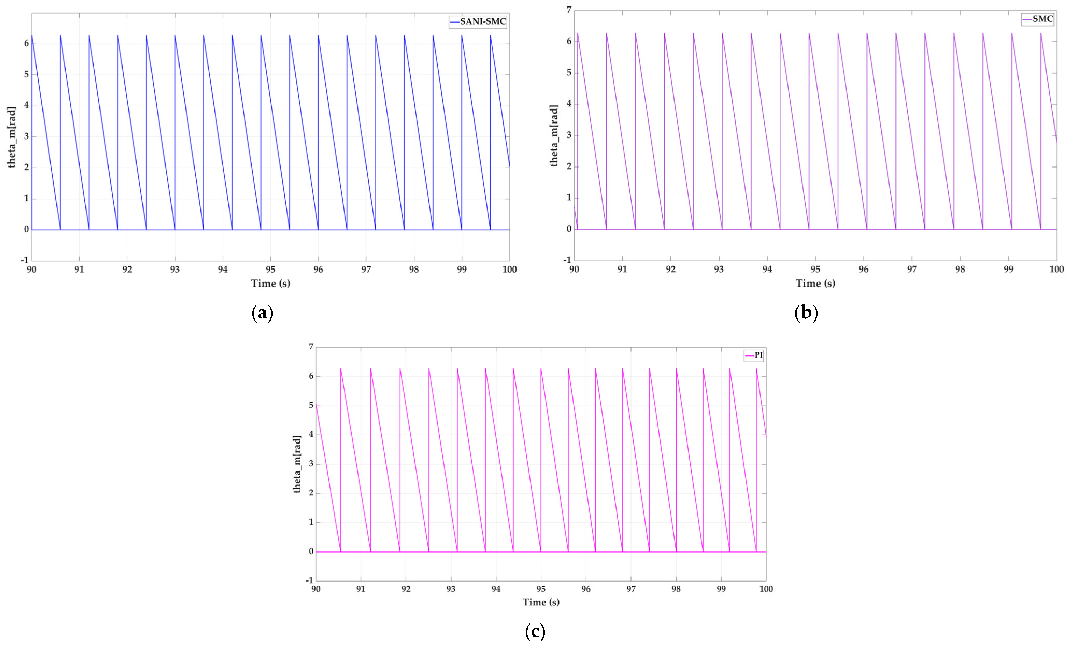
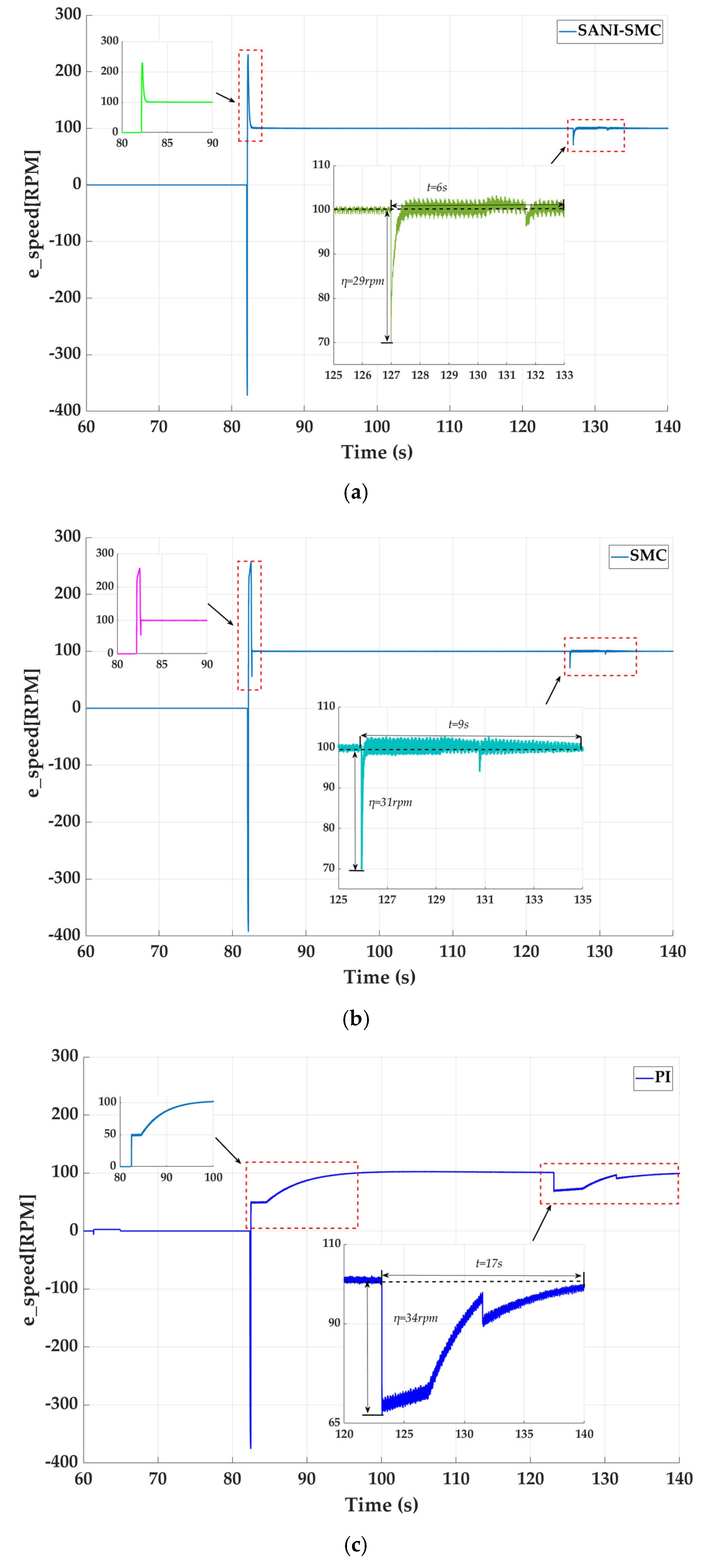
A motor loading experiment was conducted to evaluate the anti-external interference performance of the electric propulsion system. The motor speed was set to 100 r/min and controlled by the SANI-SMC, SMC, and PI controller, respectively. A torque of 1.2 N·m was suddenly applied after the motor had run stably at the set speed. The change in the torque angles is shown in Figure 7. It can be seen that the three controllers all have high robustness for sudden loading disturbances. The speed variation after loading is shown in Figure 8. The comparison results are presented in Table 3.
The speed waveform presented in Figure 8 was partially magnified and analyzed. After the sudden loading, it fluctuates downward by 34 rpm compared to the speed of the electric propulsion system controlled by the PI controller, and then returns to its rated speed after a duration of 17 s. The recovery process still produces two strong oscillations. Compared with the PI controller, the speed oscillation and recovery time of the SMC are significantly improved. However, the disturbance generated by the system is more significant. For the SANI-SMC, the amplitude of oscillation and the recovery time both are less than those of the PI controller and SMC. This means that the proposed SANI-SMC has the best control effect and exhibits the highest robustness. Furthermore, the controller performance was evaluated through three key metrics using motor startup speed data. Specifically, the integral absolute error (IAE) of the SANI-SMC is 47.26 (83.8% reduction vs. SMC [75.56], 37.7% reduction vs. PI controller [292.76]). The integral time-weighted absolute error (ITAE) is reduced by 84.3% and 37.3%, and the integral of squared value of control input (ISV) achieved 97% and 99% reductions compared to the SMC and PI controller, respectively.

5. Conclusions

This paper presents a SANI-SMC design based on a nonlinear integral sliding surface function with an adaptive saturation gain reaching law. First, the nonlinear integral sliding surface function effectively suppresses system oscillations and mitigates loading-induced disturbances. Second, the adaptive saturation gain substantially improves speed tracking performance. Finally, comparative validation experiments were conducted for a SANI-SMC, a PI controller, and a conventional SMC using an established semi-physical simulation platform. The results demonstrate that the SANI-SMC outperforms both the PI controller and SMC in velocity tracking, achieving faster response times, significantly reducing IAE, ITAE, and the control input ISV. Additionally, the SANI-SMC exhibits enhanced robustness against disturbances and uncertainties. In future studies, we will conduct further research on ship propulsion motor control. A ship-propeller model will be implemented on the experimental platform to accurately simulate real-world ship load characteristics. The proposed controller will be employed to regulate the system, with ongoing optimization of the control strategy to enhance performance.

Author Contributions

X.W.: conceptualization, methodology, software, validation, formal analysis, writing—original draft; Z.L.: data curation; P.Z.: data curation; B.J.: supervision; R.L.: supervision; Y.X.: conceptualization, funding acquisition, resources, supervision, writing—review and editing. All authors have read and agreed to the published version of the manuscript.

Funding

This research was funded in part by the Natural Science Foundation of Guangdong province under Grant 2023A1515012056, in part by the Young Creative Talents Project of Zhanjiang under Grant 2022E05001, in part by the National Nature Science Foundation of China under Grants 52171346 and 52071090, and in part by the Guangdong Provincial Department of Education 2023 high-end equipment manufacturing key areas of ordinary colleges and universities under Grant 2023ZDZX3003 (Corresponding author: Yuanyuan Xu).

Data Availability Statement

The original contributions presented in this study are included in the article. Further inquiries can be directed to the corresponding author.

Conflicts of Interest

The authors declare no conflicts of interest.

References

  1. Skowron, M.; Orlowska-Kowalska, T.; Kowalski, C.T. Detection of permanent magnet damage of PMSM drive based on direct analysis of the stator phase currents using convolutional neural network. IEEE Trans. Ind. Electron. 2022, 69, 13665–13675. [Google Scholar] [CrossRef]
  2. Errouissi, R.; Ouhrouche, M.; Chen, W.H.; Trzynadlowski, A.M. Robust nonlinear predictive controller for permanent-magnet synchronous motors with an optimized cost function. IEEE Trans. Ind. Electron. 2011, 59, 2849–2858. [Google Scholar] [CrossRef]
  3. Rivera, S.A.; Kouro, S.; Vazquez, S.B.; Goetz, S.M.; Lizana, R.; Romero-Cadaval, E. Electric vehicle charging infrastructure: From grid to battery. IEEE Ind. Electron. Mag. 2021, 15, 37–51. [Google Scholar] [CrossRef]
  4. Bostanci, E.; Moallem, M.; Parsapour, A.; Fahimi, B. Opportunities and challenges of switched reluctance motor drives for electric propulsion: A comparative study. IEEE Trans. Transp. Electrif. 2017, 3, 58–75. [Google Scholar] [CrossRef]
  5. Li, X.; Xue, Z.; Yan, X.; Zhang, L.; Ma, W.; Hua, W. Low-complexity multivectorbased model predictive torque control for PMSM with voltage preselection. IEEE Trans. Power Electron. 2021, 36, 11726–11738. [Google Scholar] [CrossRef]
  6. Zhao, K.; Liu, W.; Zhou, R.; Dai, W.; Wu, S.; Qiu, P.; Yin, Y.; Jia, N.; Yi, J.; Huang, G. Model-free fast integral terminal sliding-mode control method based on improved fast terminal sliding-mode observer for PMSM with unknown disturbances. ISA Trans. 2023, 143, 572–581. [Google Scholar] [CrossRef]
  7. Tursini, M.; Parasiliti, F.; Zhang, D. Real-time gain tuning of PI controllers for high-performance PMSM drives. IEEE Trans. Ind. Appl. 2002, 38, 1018–1026. [Google Scholar] [CrossRef]
  8. Yang, J.; Chen, W.H.; Li, S.; Guo, L.; Yan, Y. Disturbance/uncertainty estimation and attenuation techniques in PMSM drives—A survey. IEEE Trans. Ind. Electron. 2016, 64, 3273–3285. [Google Scholar] [CrossRef]
  9. Xu, B.; Zhang, L.; Ji, W. Improved non-singular fast terminal sliding mode control with disturbance observer for PMSM drives. IEEE Trans. Transp. Electrif. 2021, 7, 2753–2762. [Google Scholar] [CrossRef]
  10. Rubagotti, M.; Estrada, A.; Castaños, F.; Ferrara, A.; Fridman, L. Integral sliding mode control for nonlinear systems with matched and unmatched perturbations. IEEE Trans. Autom. Control 2011, 56, 2699–2704. [Google Scholar] [CrossRef]
  11. Laghrouche, S.; Plestan, F.; Glumineau, A. Higher order sliding mode control based on integral sliding mode. Automatica 2007, 43, 531–537. [Google Scholar] [CrossRef]
  12. Pan, Y.; Yang, C.; Pan, L.; Yu, H. Integral sliding mode control: Performance, modification, and improvement. IEEE Trans. Ind. Inform. 2017, 14, 3087–3096. [Google Scholar] [CrossRef]
  13. Yin, Y.; Liu, L.; Vazquez, S.; Xu, R.; Dong, Z.; Liu, J.; Leon, J.I.; Wu, L.; Franquelo, L.G. Disturbance and uncertainty attenuation for speed regulation of PMSM servo system using adaptive optimal control strategy. IEEE Trans. Transp. Electrif. 2022, 9, 3410–3420. [Google Scholar] [CrossRef]
  14. Zhang, X.; Sun, L.; Zhao, K.; Sun, L. Nonlinear speed control for PMSM system using sliding-mode control and disturbance compensation techniques. IEEE Trans. Power Electron. 2012, 28, 1358–1365. [Google Scholar] [CrossRef]
  15. Li, S.; Zong, K.; Liu, H. A composite speed controller based on a second-order model of permanent magnet synchronous motor system. Trans. Inst. Meas. Control 2011, 33, 522–541. [Google Scholar]
  16. Hosseinabadi, P.A.; Mekhilef, S.; Pota, H.R.; Kermadi, M. Chattering-Free Fixed-Time Robust Sliding Mode Controller for Grid-Connected Inverters Under Parameter Variations. IEEE J. Emerg. Sel. Top. Power Electron. 2024, 12, 579–592. [Google Scholar] [CrossRef]
  17. Hosseinabadi, P.A.; Pota, H.; Mekhilef, S.; Konstantinou, G.; Negnevitsky, M.; Mohamadian, S. Three-Phase Phase-Locked Loop Based on Terminal Sliding Mode for Grid-Connected Inverters. IEEE Trans. Ind. Electron. 2024, 72, 4776–4787. [Google Scholar] [CrossRef]
  18. Hosseinabadi, P.A.; Mekhilef, S.; Pota, H.; Kermadi, M.; Konstantinou, G.; Negnevitsky, M. Finite-Time Robust Controller Using Sliding Mode Approach for Grid-Connected Inverters Under Unbalanced and Weak Grids. IEEE Trans. Ind. Appl. 2025, 1–13. [Google Scholar] [CrossRef]
  19. Elmas, C.; Ustun, O. A hybrid controller for the speed control of a permanent magnet synchronous motor drive. Control Eng. Pract. 2008, 16, 260–270. [Google Scholar] [CrossRef]
  20. Chang, X.; Liu, L.; Ding, W.; Liang, D.; Liu, C.; Wang, H.; Zhao, X. Novel nonsingular fast terminal sliding mode control for a PMSM chaotic system with extended state observer and tracking differentiator. J. Vib. Control 2017, 23, 2478–2493. [Google Scholar] [CrossRef]
  21. Li, Y.; Son, J.B.; Lee, J.M. PMSM speed controller using switching algorithm of PD and Sliding mode control. In Proceedings of the 2009 ICCAS-SICE, Fukuoka, Japan, 18–21 August 2009; IEEE: Piscataway, NJ, USA, 2009; pp. 1260–1266. [Google Scholar]
  22. Song, Q.; Jia, C. Robust speed controller design for permanent magnet synchronous motor drives based on sliding mode control. Energy Procedia 2016, 88, 867–873. [Google Scholar] [CrossRef]
  23. Guo, Y.; Long, H. Self organizing fuzzy sliding mode controller for the position control of a permanent magnet synchronous motor drive. Ain Shams Eng. J. 2011, 2, 109–118. [Google Scholar] [CrossRef]
  24. Zhang, L.; Tao, R.; Zhang, Z.X.; Chien, Y.-R.; Bai, J. PMSM non-singular fast terminal sliding mode control with disturbance compensation. Inf. Sci. 2023, 642, 119040. [Google Scholar] [CrossRef]
  25. Liu, W.; Chen, S.; Huang, H. Adaptive nonsingular fast terminal sliding mode control for permanent magnet synchronous motor based on disturbance observer. IEEE Access 2019, 7, 153791–153798. [Google Scholar] [CrossRef]
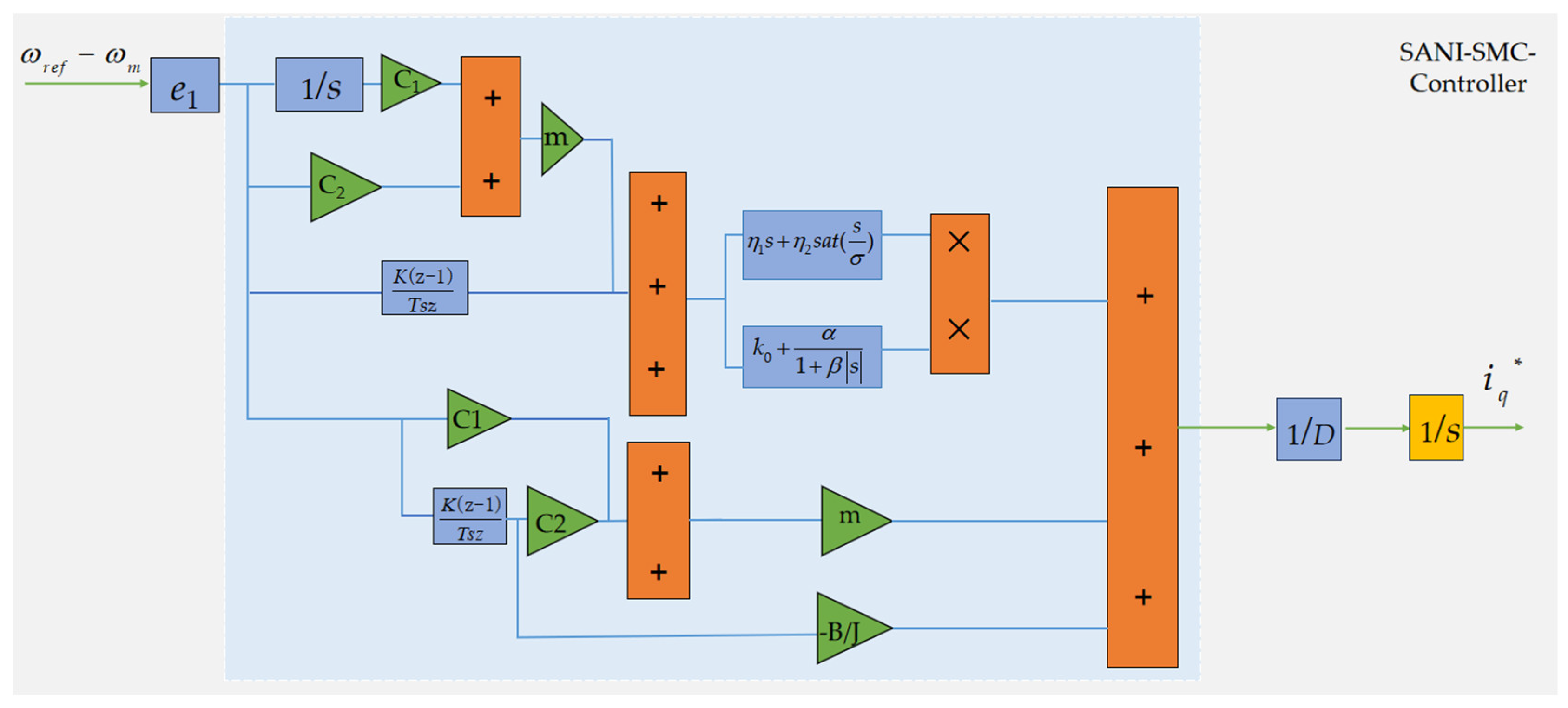
Figure 1. Structure diagram of the designed SANI-SMC.
Jmse 13 00976 g001
Figure 2. Structure diagrams of the conventional PI speed loop controller and the traditional exponential SMC sliding mode controller: structure diagrams of the SMC (a) and PI controller (b).
Jmse 13 00976 g002
Figure 3. A structure diagram of the novel sliding mode control.
Jmse 13 00976 g003
Figure 4. Experimental platform.
Jmse 13 00976 g004
Figure 5. The speed dynamic responses of the PMSM under three controllers: SANI-SMC (a), SMC (b), and PI controller (c).
Jmse 13 00976 g005aJmse 13 00976 g005b
Figure 6. Variation in the three-phase current of the propulsion motor corresponding to the three controller functions of the speed: SANI-SMC (a), SMC (b), and PI controller (c).
Jmse 13 00976 g006aJmse 13 00976 g006b
Figure 7. The variation in the torque angle after loading under the SANI-SMC (a), SMC (b), and PI controller (c).
Jmse 13 00976 g007
Figure 8. The variation in the speed of the electric propulsion system after loading under the SANI-SMC (a), SMC (b), and PI controller (c).
Jmse 13 00976 g008
Table 1. Parameters of the PMSM prototype.
SymbolQuantityValue
RsData stator resistance 1.29 Ω
fRated frequency100 Hz
NRated speed500 rpm
Ldd-axis inductance2.53 mH
Lqq-axis inductance2.53 mH
PnNumber of pole-pairs4
pRated power1.5 kw
JMoment of inertia0.00194 kg·m2
φfPermanent magnet flux linkage0.2 Wb
Table 2. Comparison of the startup performance of the PMSM under the three different controllers.
StatusUnitSANI-SMCSMCPI
Startup Status∂ (rpm)605690475
η (rpm)234
t (s)128
Acceleration stateη (rpm)1570
t (s)0.51.515
Table 3. Comparison of control performance of three controllers.
ControllerResponse Time (s)Speed Fluctuation (rpm)
SNIA-SMC629
SMC931
PI1734
Disclaimer/Publisher’s Note: The statements, opinions and data contained in all publications are solely those of the individual author(s) and contributor(s) and not of MDPI and/or the editor(s). MDPI and/or the editor(s) disclaim responsibility for any injury to people or property resulting from any ideas, methods, instructions or products referred to in the content.