Abstract
Maritime Autonomous Surface Ships (MASSs) incorporate advanced digital technologies, thus rendering their systems more complex and diverse than those of conventional ships. Furthermore, the operation of MASSs, which introduces new risks not encountered in conventional ship operations, differs significantly from that of conventional manned vessels. These challenges highlight the necessity for a more systematic and structured approach to risk analysis and control. This study presents a qualitative risk assessment methodology to identify and manage hazardous scenarios associated with MASS operations systematically. The key feature of the proposed methodology is the integration of cognitive model-based functional analysis with the widely adopted hazard identification (HAZID) method, which enables a structured and comprehensive analysis process. Functional analysis is used to examine the functions required for MASS operations and to analyze interconnected systems to fulfill these functions. Subsequently, HAZID is performed to identify hazardous scenarios that may cause functional degradation or failure. To illustrate the proposed methodology, a case study is presented based on a qualitative risk assessment conducted in preparation for the field trial of an Autonomous Navigation System. Practical applications, including the presented case study, demonstrated the effectiveness of this methodology as a systematic tool for identifying and evaluating potentially hazards in MASS operations.
1. Introduction
In recent years, rapid advancement in information and communication technologies and related digital innovations has driven significant interest in autonomous maritime systems. These technologies, aimed at minimizing human intervention, have facilitated field trial operations of autonomous systems [1] and increased the feasibility of their commercial deployment. Recognizing the potential implications of such technological advancements, the International Maritime Organization (IMO) has acknowledged the necessity for robust regulatory measures to ensure the safety of human life at sea, on property, and in the marine environment. Since the 99th session of the Maritime Safety Committee (MSC 99), the IMO has initiated discussions on Maritime Autonomous Surface Ships (MASSs) and is currently developing the MASS Code to ensure the safe operation of MASSs and their coexistence with conventional vessels [2,3,4].
MASS technology is expected to enhance operational efficiency, environmental sustainability, and maritime safety [5,6,7,8,9,10,11,12]. However, adopting new technologies and the corresponding operational paradigms tends to introduce a range of novel risks distinct from those associated with conventional ship operations, thus underscoring the necessity for advanced risk assessment methodologies to systematically analyze and control emerging hazards [5,13,14].
Recent systematic review articles [13,15,16] have indicated a steady growth in research on risk assessment methodologies for MASSs since the initiation of IMO discussions. Tao et al. [13] analyzed 62 studies related to MASSs, classifying risk-influencing factors (RIFs) into human-related, vessel-related, environmental, and technological factors, and further examined 23 studies that focused specifically on risk assessment methodologies and data sources. Chaal et al. [15] conducted a bibliometric review of 417 papers published between 2011 and 2022 and performed a detailed analysis of the 30 most cited works concerning the methodologies and formats used for MASS risk assessment. Similarly, Yuzui and Kaneko [16] applied the PRISMA (Preferred Reporting Items for Systematic Reviews and Meta-Analyses) framework to select 47 relevant studies published between January 2018 and March 2023, categorizing them according to risk analysis types and tools, target indices (e.g., risk levels and failure rates), risk types (e.g., safety and cybersecurity), MASS type, and accident type. These reviews indicate that the System-Theoretic Process Analysis (STPA) [17,18,19,20,21,22] is the most commonly used approach for qualitative risk assessment, whereas Bayesian Networks (BNs) [23,24,25] are frequently applied for quantitative risk assessment. Other notable methodologies include Failure Modes and Effects Analysis (FMEA) [26,27], Human Factors Analysis and Classification System (HFACS) [28], Fault Tree Analysis (FTA) [29], and several others [30,31,32]. In many studies, these techniques are used in combination to meet the specific requirements of risk assessment objectives, for example, integrating STPA with BN [33,34,35,36,37] or combining FTA, BN, and Event Sequence Diagrams (ESDs) [38,39,40]. A key point emphasized across these systematic reviews is the increasing necessity for structured and effective risk assessment methodologies customized to MASSs, whether for developing novel approaches or adapting to existing ones. Thus, we developed a MASS-specific risk assessment framework as part of the “Development of Autonomous Ship Technology” R&D project under the Korea Autonomous Surface Ship (KASS) Project [41]. This study focuses on a qualitative risk assessment methodology within this framework.
While a range of qualitative risk assessment frameworks for MASSs has been proposed in previous studies, techniques such as STPA and FMEA have proven effective for detailed analyses involving control logic among components in autonomous systems. In addition, efforts to quantify risks by combining techniques like BNs, FTA, and ESDs have also been observed. However, this paper aims to propose a qualitative risk assessment methodology that is suitable for analyzing risks associated with MASS operations, particularly in light of the complexity of MASS operations and their unique human–system interaction challenges. The proposed methodology distinguishes itself by explicitly considering the functional requirements and interactions specific to MASS operations, while also being structured to facilitate future integration with quantitative risk modeling. The following considerations were taken into account in the development of this methodology.
A well-structured qualitative risk assessment methodology for MASSs should exhibit the following characteristics: (1) enable effective comparison with conventional ships to confirm that MASSs achieve at least an equivalent level of safety, (2) be sufficiently flexible and intuitive to be applicable across various system designs intended to meet MASS operational requirements, and (3) facilitate integration with quantitative risk assessment methodologies. To fulfill these requirements, this study proposes a methodology that combines cognitive model-based functional analysis with a hazardous scenario identification process, with emphasis on identifying functional degradation and failure scenarios from an operational perspective. Functional analysis is adopted to compare MASSs with conventional ships in terms of the required operational functions to satisfy the first requirement. Second, the methodology incorporates Functional Flow Diagrams to visualize the operational sequence of system functions intuitively and applies the widely used hazard identification (HAZID) method to identify risk factors that may cause functional degradation or failure. To support integration with quantitative approaches, the methodology also includes the development of logic-gate-based Functional Blocks, which enable the transformation of Functional Flow Diagrams into Fault Trees or Reliability Block Diagrams (RBDs).
A detailed explanation of this methodology is provided in Section 2, beginning with a brief overview of the overall MASS risk assessment framework. Section 3 presents a case study of qualitative risk assessment applied to an Autonomous Navigation System (ANS) field trial conducted in accordance with the IMO’s Interim Guidelines for MASS Trials (MSC.1/Circ.1604). Section 4 discusses the key insights from applying the methodology, and Section 5 concludes the paper.
2. Methods
2.1. Scope and Concept
In ship and system design approval, traditional prescriptive regulations may limit the level of innovation that can be realized during the design process. Consequently, several IMO conventions include provisions accommodating alternatives and/or equivalent designs. To enable the widespread adoption of innovative and alternative/equivalent designs, it is essential to establish a predictable and reliable approval process that maximally leverages state-of-the-art risk assessment tools and techniques [42]. Risk assessment for innovative and alternative/equivalent designs is typically conducted during the system design phase, thus providing critical information for decision-making in both safe system design and the approval process. A thorough analysis of the risks associated with the operation of the target system can provide crucial information for sound decision-making and offer a clear justification for decisions made during the design and approval processes.
However, from a risk assessment perspective on the operation of MASSs incorporating innovative technologies, one must discuss whether design-phase risk assessments for approval alone can sufficiently guarantee the safety of MASSs. In particular, to operate advanced systems that drastically reduce human intervention, one may be required to implement real-time risk assessment methodologies to evaluate various dynamic operational variables and support decision-making (whether by humans or the system) to ensure safe system operation. Figure 1 presents the proposed overall risk assessment procedure applicable to both the design and operational phases of MASSs. This study focused exclusively on the qualitative risk assessment component of the overall process. For convenience, the methodology proposed in this paper will be referred to as the “Cognitive Model-based Functional Analysis and Hazard Identification” technique (hereinafter “COFA-HAZID”).
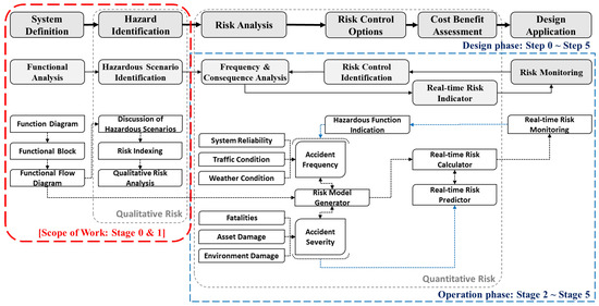
Figure 1.
Risk assessment procedure for MASSs.
Before providing a detailed explanation of the COFA-HAZID method, this section outlines the broader conceptual framework for MASS risk assessment, particularly the concept of real-time risk assessment during the operational phase. This overview is intended to help readers understand the rationale behind integrating functional analysis with HAZID into the COFA-HAZID procedure.
The risk assessment framework shown in Figure 1 encompasses both design- and operational-phase risk assessment processes, thus supporting the evaluation of risk levels across the entire lifecycle of the MASS and ensuring that risks are controlled to a level that allows for safe operation. Because the design-phase risk assessment process (Steps 0–5 in Figure 1) broadly aligns with the procedures already applied to innovative or alternative/equivalent designs, this study does not explain those steps. In the operational phase, the real-time risk assessment concept (Stages 0–5 in Figure 1) is applied based on the results of the design-phase risk assessment, thereby enabling continuous risk evaluation throughout MASS operations.
The first stage of the risk assessment process is the “Functional Analysis Stage (Stage 0)”, which involves analyzing the functions associated with MASS operation to define the system and the scope of risk assessment. Functional analysis begins with developing a functional diagram, followed by creating Functional Blocks combined to construct a Functional Flow Diagram. This process allows the analysis of the interrelationships between subsystems from a functional perspective. Upon completion of the functional analysis, the Hazardous Scenario Identification Stage (Stage 1) is conducted. At this stage, hazardous scenarios are identified based on the potential causes and consequences of functional degradation or failure associated with the functions identified in the Functional Analysis Stage. The HAZID study methodology, which is widely used in various industries, is proposed to identify hazardous scenarios related to the operation of the MASS. The major accident scenarios are grouped to define the initial events among the hazardous scenarios identified in the Hazardous Scenario Identification Stage. Subsequently, the causes of the initial events, possible event propagation scenarios, and potential consequences of accidents are analyzed in detail to quantify the risks in the Frequency and Consequence Analysis Stage (Stage 2). For the quantification of risk, a Risk Model Generator is proposed to support this process using FTA or RBDs for frequency estimation and Event Tree Analysis (ETA) for consequence estimation. Fault Trees or RBDs are automatically generated based on the Functional Flow Diagram developed in Stage 0, thus facilitating the estimation of the initial event occurrence frequencies and system failure probabilities. The feasibility of real-time risk assessment during the operational phase of MASSs depends on the availability of real-time operational data. In the operational phase, real-time risk is derived by inputting real-time data pertaining to system reliability, vessel traffic density, and meteorological conditions into the Risk Model Generator. In the Real-Time Risk Indicator Stage (Stage 4), real-time risk is computed based on the output of the Risk Model Generator and presented to decision-makers, whether they are human operators or autonomous systems. In the Risk Control Identification Stage (Stage 3), the results from the Real-Time Risk Indicator are used to assess the subsystems that may be responsible for functional degradation or failure. Potential risk control measures are identified, such as implementing alternative systems to replace failed ones. The Risk Model Generator calculates the predicted risk levels using these control measures. Decision-makers can select and apply the appropriate risk mitigation strategies by comparing real-time risk estimates from the Real-Time Risk Indicator with the predicted risks. Finally, in the Risk Monitoring Stage (Stage 5), real-time risk monitoring is performed to oversee and maintain the effectiveness of the risk assessment from Stages 2 to 4.
The COFA-HAZID methodology specifically addresses the qualitative risk assessment process described in Stages 0 and 1, shown in Figure 1, and is developed by considering its integration with the subsequent quantitative risk assessment process (Stages 2 to 4).
2.2. Functional Analysis: Stage 0
Generally, systems rely on human control, supervision, and operations to perform their intended functions. Unlike conventional systems, autonomous ships and systems offer extended functionalities encompassing areas that typically require human intervention to achieve operational objectives. Therefore, one must comprehensively examine these extended functions, the subsystems constituting the overall system, and the interactions with other connected systems to perform these functions. Functional analysis was conducted by adopting the following procedure to facilitate a clear understanding of the target system and systematically establishing the fundamental information necessary for identifying hazardous scenarios related to the operation of the system.
- Define Target System and Risk Assessment Scope.
- Define Function Diagram.
- Develop Functional Blocks.
- Analyze the Functional Flow Diagram.
All risk assessment processes begin with a clear definition of the target system and scope of risk assessment [43,44]. Once the scope of the risk assessment is established, the key functions and subfunctions of the system are defined based on the functional requirements for ship operations. Considering the operational characteristics of the system, the key functions and subfunctions are further refined to a level appropriate for the risk assessment scope. Once the functions and the Function Diagram are finalized properly, Functional Blocks are developed for the lowest-level functions of the Function Diagram. Subsequently, these Functional Blocks are used to construct a Functional Flow Diagram, which is analyzed to review the interrelationships among the constituent systems.
2.2.1. Function Diagram: Function Decomposition
The COFA-HAZID methodology approaches risk assessment from the perspective of ship operations. Fundamentally, it is used to analyze potential function omissions, the necessity for additional functions, and the role of alternative functions by comparing the functional requirements of conventional ship operations with those of the target system under risk assessment (i.e., MASS). Based on the functions required for ship operations, the functions related to the operation of MASSs are identified and represented in a Function Diagram, as shown in Figure 2.
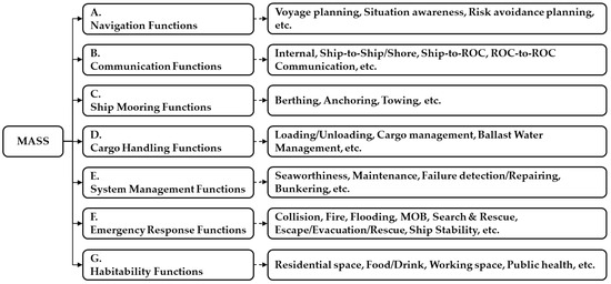
Figure 2.
Function diagram for MASSs.
The key functions of MASSs can be further decomposed into subfunctions and sub-subfunctions. The function decompositions related to the navigation and communication functions in ship operations are illustrated in Figure 3 and Figure 4, respectively.
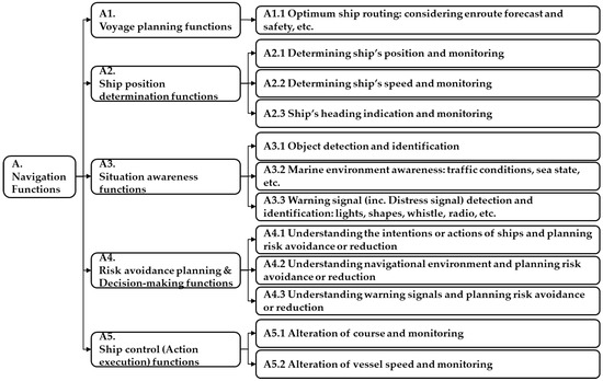
Figure 3.
Function diagram for navigation functions.
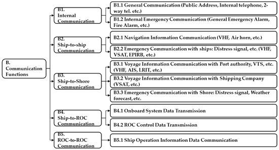
Figure 4.
Function diagram for communication functions.
The decomposition level in a functional diagram may vary depending on the purpose of risk assessment and its scope. It should allow the understanding of the system composition and the functions of its subsystems. Additionally, the functions must be decomposed to a level that enables the construction of Functional Blocks suitable for achieving the risk assessment objectives.
2.2.2. Functional Block
The Functional Block is designed based on the concepts of the Cognitive Model [45,46] and Intelligent Agents [47], as illustrated in Figure 5, and is used to provide structured information for systematically identifying potential hazardous scenarios that may arise during functional failure. The Cognitive Model and Intelligent Agents approach adopts a structured process for risk recognition and response, and comprises the following stages: “Pre-task planning”, “Risk perception (from Input sensors)”, “Situation awareness”, “Risk control planning and Decision-making”, “Execution of a risk control option (to Output actuators)”, and “Monitoring of risk control option execution”. The concepts of Cognitive Models and Intelligent Agents are applied in functional analysis to identify the (1) necessary information for function execution, (2) agents responsible for executing functions, (3) purpose of each function, and (4) outputs generated through function execution. In conventional ships, an agent is generally considered a human crew member, whereas in MASSs, it can be an autonomous system or an embedded Artificial Intelligence (AI) algorithm.
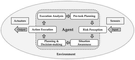
Figure 5.
Cognitive Models and Intelligent Agents.
Once a Function Diagram is developed, the corresponding Functional Blocks are constructed based on the concepts of Cognitive Models and Intelligent Agents. As shown in Figure 6a, a Functional Block comprises the following four main components:
- Input: Information or sensor data required to execute the lowest-level function.
- Agent: Someone or something that perceives its environment through sensors and acts according to that environment through actuators [47].
- Function Description: The description of the function represented by the Functional Block.
- Output: Output information or actuator actions resulting from executing the lowest-level function.

Figure 6.
Concept of Functional Block: (a) Functional Block for basic concept; (b) Functional Block for OR gate concept; (c) Functional Block for AND gate concept.
Figure 6.
Concept of Functional Block: (a) Functional Block for basic concept; (b) Functional Block for OR gate concept; (c) Functional Block for AND gate concept.
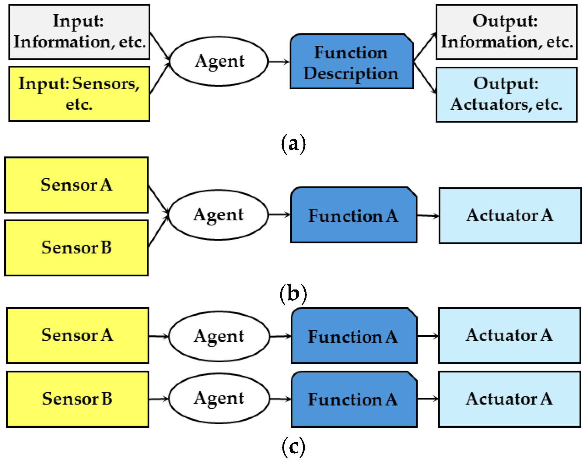
Each Functional Block represents the functional execution flow, where the “Agent” receives “Input” from information sources or sensors and generates an “Output” (information or actuator execution) to achieve the intended system function. For example, in Figure 3, functions “A1.1 Optimum Ship Routing Function” to “A5.2 Alteration of Vessel Speed and Monitoring Function” are selected as the lowest-level functions to develop Functional Blocks, which are then used to construct a Functional Flow Diagram representing the functional execution flow of a key function (e.g., A. Navigation Functions).
To illustrate the interconnections between the input and output systems required for function execution, the Functional Block utilizes logic gate concepts such as OR and AND gates, as depicted in Figure 6b,c. From the perspective of failure propagation, if both Sensors A and B are required to satisfy Function A, then an OR gate is used (i.e., if either Sensor A or B fails, then Function A fails as well). If Function A can be performed using either Sensor A or Sensor B, then an AND gate is used (i.e., Function A fails only if both Sensors A and B fail). By adopting Functional Blocks based on logic gate concepts, the relationships between the systems involved in function execution and the system configurations (e.g., redundancy arrangements) implemented to satisfy the function can be analyzed.
2.2.3. Functional Flow Diagram
The Functional Blocks are interconnected to construct a Functional Flow Diagram. A Functional Flow Diagram is used to examine the functional requirements of the target system and analyze the overall functional execution flow necessary to achieve the intended key functions.
For example, in the case of conventional ship operations, the Functional Flow Diagram for open-sea navigation is as shown in Figure A1 (Appendix A). In a conventional ship, the Officer of the Watch (OOW) formulates a voyage plan (initial route planning) based on navigational experience, weather forecast information, etc. The position, speed, and heading of the ship are continuously monitored to maintain its operational status. The Second Officer and the Captain generally develop voyage planning; however, for simplicity, all agents responsible for performing navigation functions are assumed to be the OOW in developing the Functional Blocks. Functions such as object detection, traffic environment recognition, and emergency signal recognition are maintained for situational awareness. When a hazardous situation arises, the ship determines an alternative route and/or speed to avoid danger and executes risk avoidance actions, if necessary. Communication functions, including ship-to-ship and ship-to-shore communications, are partially incorporated into the Functional Flow Diagram for risk control planning and decision-making.
2.3. Hazardous Scenario Identification: Stage 1
Hazard identification is a qualitative risk assessment methodology aimed at identifying all potential hazards in MASS operations and reducing the associated risks to acceptable levels by implementing appropriate control measures to protect human life, property, and the environment. Based on the functional analysis results, this study applies the HAZID methodology to identify hazardous scenarios associated with functional degradation or failure. The objectives of conducting the HAZID study on MASSs are as follows:
- To systematically identify potential hazards associated with the operation of MASSs.
- To identify the possible causes associated with the identified hazards.
- To identify the potential impact of hazards on human life, the environment, and assets.
- To review the adequacy of existing safeguards associated with the identified hazards.
- To propose additional safety actions and recommendations aimed at further enhancing the overall safety of the MASS.
2.3.1. Discussion of Hazardous Scenarios
In Stage 0 (Functional Analysis) of the risk assessment process for MASS, Function Diagrams, Functional Blocks, and Functional Flow Diagrams are developed to identify functions related to system operation and analyze the overall functional flow required for system operation. By contrast, Stage 1 (Hazardous Scenario Identification) involves identifying potentially hazardous scenarios. Expert brainstorming was conducted and supported by HAZID Worksheets to facilitate this step. Figure 7 shows two main components: a Function Description Column and a Hazard Identification Column. The functional analysis results from Stage 0 are recorded in the Function Description Column. Experts participating in the HAZID Workshop reviewed the functional analysis results, based on which hazardous scenarios were identified via expert brainstorming. All the outcomes of the brainstorming process were recorded in the Hazard Identification Column.
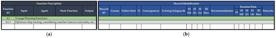
Figure 7.
Example of HAZID Worksheets: (a) Function Description Column; (b) Hazard Identification Column.
During the expert brainstorming process for hazardous scenario identification, the following potentially hazardous situations were systematically considered for each Functional Block:
- Errors in the Input information required to perform the lowest-level function, such as data integrity errors and sensor equipment failures.
- Failures of the “Agent” performing the lowest-level function, including human errors such as mis-operation or unfamiliarity with the system (if the agent is a human) and system errors such as system malfunction or failure (if the agent is an autonomous system), etc.
- “Function” degradation or loss: hazards affecting the function, effects of function loss on other systems, etc.
- Errors in the Output Information obtained by performing the lowest-level function: effects of data integrity error on other connected systems and actuator equipment failure.
During the expert brainstorming process, discussions may include errors related to the Input, Agent, Function, and Output of Functional Blocks; methods for detecting such errors; potential impacts of the errors; measures to reduce the likelihood of their occurrence; and strategies to mitigate their consequences. In addition to the above hazardous situations, conventional HAZID guidewords (refer to Table 1) were also used as secondary prompts during the expert brainstorming to identify the causes of hazardous scenarios while considering each hazardous situation.

Table 1.
Example of HAZID guidewords.
2.3.2. Risk Indexing
A qualitative risk acceptance criterion was applied to determine the importance or prioritization of the hazardous scenarios identified during the HAZID Workshop, similar to the conventional HAZID methodology. Each hazardous scenario was assigned a risk index using a Risk Matrix, as shown in Figure 8, which evaluates the combination of the Frequency Index (FI) and Severity Index (SI). The FI and SI values used for the risk ranking are listed in Table 2 and Table 3, respectively.
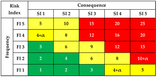
Figure 8.
Example of Risk Matrix: Red—Intolerable region; Yellow—ALARP region; Green—Tolerable region.
Table 2.
Example of Frequency Index.
Table 3.
Example of Severity Index.
The Risk Matrix was constructed by combining the Frequency Index (FI) and Severity Index (SI) values. For the qualitative risk acceptance criteria, the “As Low As Reasonably Practicable (ALARP)” principle, which is commonly accepted for maritime safety issues and recommended by the IMO FSA guidelines, was considered for risk evaluation [43,44].
2.3.3. Outcomes of Qualitative Risk Assessment
This chapter introduces the COFA-HAZID methodology, which is a qualitative risk assessment approach that integrates Functional Analysis with the HAZID methodology. The outcomes of applying the COFA-HAZID methodology are as follows:
- A list of key functions (and subfunctions) required for the MASS operation decomposed to a level suitable for the scope of risk assessment: Function Diagrams.
- The Input, Agent, and Output information for each lowest-level function, including information regarding the interacting systems: Functional Blocks.
- The Functional flow information for each key function necessary for MASS operation: Functional Flow Diagram.
- ✓
- Comparative analysis of functional differences between conventional ships and MASSs from an operational perspective.
- ✓
- Identification of unnecessary or additionally required functions in MASSs compared with conventional ship operations.
- A list of hazardous scenarios related to functional failure or degradation, each with an assigned risk index.
- ✓
- Root causes and consequences of each scenario.
- ✓
- Distribution of hazardous scenarios by function.
- A list of existing safety measures incorporated into the system design.
- A list of recommended additional risk control measures, including
- ✓
- Design or operational improvements to fulfill functional requirements.
- ✓
- Functional substitution strategies for maintaining the functions required for MASS operations, including system redundancy and alternative systems.
- Comparison of inherent and residual risks after applying additional risk control measures.
3. Qualitative Risk Assessment for Autonomous Navigation System
This chapter presents a case study, selected as the only example available for public disclosure, from several qualitative risk assessments conducted to support field trial operations of Autonomous Navigation Systems in accordance with the IMO Interim Guidelines for MASS Trials [1]. Notably, this case study is not related to the quantitative risk assessment for the operational phase of MASSs (Stages 2 to 5 in Figure 1) described in Section 2 but was conducted to ensure the operational safety of the KASS-Autonomous Navigation System (K-ANS hereinafter) during its field trials.
3.1. Target System Overview
This section provides a brief overview of the design and operational concepts of the K-ANS. The KASS Project Office (Daejeon, Republic of Korea) [41] designated a 1800 TEU-class container ship as a demonstration vessel to verify autonomous ship technologies developed under the KASS Project. This project aims to conduct performance verification based on actual operational conditions by equipping the vessel with the systems developed through the project and acquiring operational data. This case study focuses on the K-ANS, which is an autonomous navigation solution developed in the KASS Project. A simplified diagram illustrating the system configuration is shown in Figure 9. Systems related to the operation of the K-ANS are highlighted in bold in the diagram, whereas the systems not included in the case study are displayed in faded form.
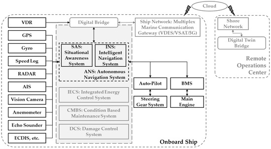
Figure 9.
Simplified system diagram for KASS-Autonomous Navigation System.
The K-ANS comprises a Situational Awareness System and an Intelligent Navigation System. It detects target vessels and objects using RADAR, the Automatic Identification System (AIS), vision cameras, and LiDAR. Additionally, based on the detected targets and the planned route, it generates a safe navigation route (i.e., a collision avoidance route) and provides control commands to the Autopilot and Bridge Maneuvering System (BMS). This system was developed while considering the vessel’s operational environment and hardware configuration for field trials; additionally, it was designed to interface with existing navigation systems.
The Situational Awareness System receives input directly from detection and navigation sensors or via the Digital Bridge, and it recognizes surrounding vessels and marine obstacles. The Intelligent Navigation System receives the output from the Situational Awareness System along with additional navigation sensor data (e.g., anemometer, echo sounder, and loading computer), generates waypoints to guide the vessel to a target point for collision avoidance, and issues engine and rudder control commands for waypoint tracking control. Regarding the Operational Design Domain (ODD) of the K-ANS, although the system is designed to be operable in any sea area, its deployment onboard a demonstration vessel imposes certain constraints. For the field trials, the system was intended to operate only in open seas located more than five nautical miles from the territorial sea baseline. Furthermore, during operation in the K-ANS Control Mode, the standard practice of bridge watchkeeping must be maintained at all times as a fundamental operational concept. The basic operational conditions related to the weather and environmental factors are as follows:
- Wave height ≤ 2 m.
- Wind class ≤ Beaufort Number 6.
- Current ≤ 3 knots.
- Visibility ≤ 6 NM.
- Cross Track Error (XTE) ≤ 2 NM.
3.2. Results of Functional Analysis
Functional analysis was conducted to identify the functions associated with the operation of the K-ANS and to examine its interactions with other systems. Additionally, the analysis aimed to compare the operational functions of the K-ANS with those of conventional manned vessels. The K-ANS functions identified for the field trial are based on the navigation functions presented in Figure 3, and the functions of the K-ANS are summarized in Table 4.
Table 4.
Functional description of the KASS-Autonomous Navigation System for field trial.
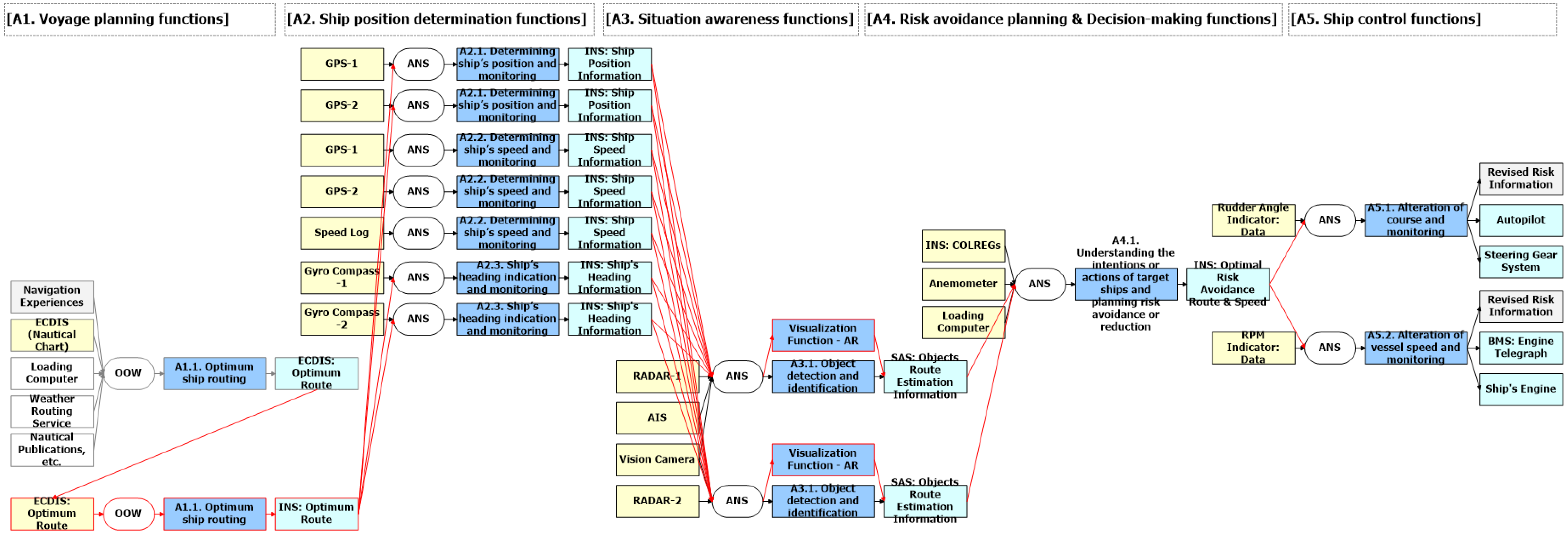
The Functional Flow Diagram for the field trial operations in open seas from the operational perspective of the K-ANS is presented in Figure A2 (Appendix A). A summary of the reviews for each lowest-level function is presented as follows:
Function A1. Voyage planning functions: The K-ANS features an Economic Operation Route Planning Function (initial voyage planning for economic operation) and a Safe Navigation Route Planning Function (risk avoidance route selection). However, because it is scheduled to be operated temporarily in open seas for field trials, the economic operation route planning function is not intended for use during the trial. Accordingly, the initial route plan for the K-ANS was established based on the route selected by the OOW. Waypoints from the initial route configured in the Electronic Chart Display and Information System (ECDIS) were uploaded to the K-ANS by the OOW. Although an economic operation route planning function was not used, the engine Revolutions Per Minute (RPM) control function was utilized during navigation to maintain the optimal speed along the selected route. Notably, in contrast to other ANSs assessed through qualitative risk assessments, the K-ANS does not employ an officially certified electronic navigational chart (ENC). This has been identified as a specific issue and is considered a key factor that must be prioritized when operating in K-ANS Control Mode.
Function A2. Ship position determination functions: The K-ANS uses GPS data to determine the ship position. The ship speed is calculated using GPS and Speed Log data, whereas the heading information is acquired from the Gyro Compass for continuous monitoring.
Function A3. Situation awareness functions: The situation awareness system of the K-ANS combines input data from the RADAR, AIS, vision cameras, and LiDAR for object detection. However, because the detection range of LiDAR is inadequate for practical use in navigation, the LiDAR input is disregarded during the hazardous scenario identification process in the field trial. The K-ANS incorporates an augmented reality (AR)-based visualization function that enables the OOW to perceive navigational and object-related information intuitively. Compared with the navigation functions of conventional manned ships, the K-ANS partially substitutes the “look-out by eyesight” function of the OOW through visual sensors such as RADAR and vision cameras. However, the K-ANS does not include any functionality for recognizing auditory signals, such as the “look-out by hearing” function. In terms of system functions, “Function A3.1: Object Detection and Identification Function” has been implemented to some extent, whereas “Function A3.2: Marine Environment Awareness” and “Function A3.3: Warning Signal Detection and Identification” are excluded.
Function A4. Risk avoidance planning and decision-making functions: The Intelligent Navigation System of the K-ANS selects a risk avoidance route per COLREGs [48] using object detection data from the situation awareness system and uses inputs from other navigation sensors (e.g., anemometer and loading computer). As the K-ANS is devoid of a visualization function to inform the OOW of its intended risk avoidance routes ahead of time, additional measures may be required to ensure that the OOW is aware of such actions in advance.
Function A5. Ship control (action execution) functions: Once a risk avoidance route is selected, the K-ANS executes control by sending course alteration commands to the autopilot and/or speed control commands to the BMS. The current RPM and rudder-angle feedback are continuously monitored while the vessel course and/or speed are controlled. Once the risk avoidance action is completed, the Intelligent Navigation System restores the vessel to its original route.
As indicated by the functional analysis above, the K-ANS does not provide the full range of capabilities necessary for fully autonomous navigation. Therefore, a conventional manned navigation watch must be maintained. Based on the functional analysis results, the basic operational concept of the K-ANS is defined before initiating the hazardous scenario identification. The operational concept of the K-ANS used in the HAZID Workshop is as follows:
- A safe navigational watch should always be maintained continuously in accordance with basic seamanship and COLREGs, even under the K-ANS Control Mode.
- The K-ANS Control Mode may be activated only when a KASS Researcher(s) is on the bridge (considering the absence of certified electronic navigational charts in the K-ANS).
- The KASS researcher is responsible for providing the OOW with K-ANS operational information (e.g., course and speed changes or situations requiring the return of control authority to the OOW).
- The OOW shall retain the authority to initiate the control authority return procedure at any time, if necessary, for safe navigation.
- The control authority of the ship (BMS and Autopilot control) is manually returned from the K-ANS Control Mode to the OOW.
3.3. Results of Hazard Identification
Based on the Functional Blocks and flow diagram developed during the functional analysis phase (see Figure A2, Appendix A), an expert brainstorming session (HAZID Workshop) was conducted to identify potentially hazardous scenarios. During the workshop, the experts reviewed the functional analysis results, identified hazardous scenarios, and conducted a qualitative risk ranking based on expert consensus. Twenty-four experts from various fields related to MASS participated in the brainstorming sessions (see Figure 10).

Figure 10.
Details of participants in the HAZID Workshop: fields of expertise, number of experts, and average years of experience.
Through this expert brainstorming process, 23 hazardous scenarios directly related to the field trial operation of the K-ANS were identified. The inherent risk level of each scenario and the residual risk level assuming the implementation of risk control measures are illustrated in Figure 11 for comparison. To highlight changes in the risk levels, labels (Hazard IDs) are added to the data points corresponding to hazardous scenarios assigned with a Risk Index (inherent risk) of 7 or higher.
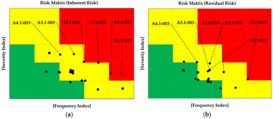
Figure 11.
Hazardous scenario distribution: (a) inherent risk; (b) residual risk.
The discussion points related to hazardous scenarios are summarized as follows (for more details, refer to Appendix B: Examples of hazardous scenarios identified):
Function A1. Voyage planning functions: The overall operational concept of the field trial, including the operational plan for the K-ANS, is discussed. The Functional Block for “A1.1 Optimum Ship Routing Function” examines route planning by the K-ANS, including the upload of initial routes by the OOW. The identified key hazardous scenarios include an unclear operational concept for the K-ANS field trials, initial route input errors, unauthorized access (cybersecurity issues), and the inability to record the K-ANS usage systematically. The recommended risk control measures include clearly defining the operational area and procedures for the field trial and specifying detailed conditions for initiating and terminating the K-ANS Control Mode based on these definitions. Furthermore, establishing procedures for transferring control authority between the K-ANS and OOW is recommended. A pre-verification procedure is proposed for the planned field trial route to identify potential navigational hazards using ENCs and other nautical publications. Concerning the integration of the K-ANS subsystems and existing navigational equipment, monitoring functions for the system status and a user interface (UI) to verify data integrity are proposed. Stronger login policies and enhanced physical security are recommended to address cybersecurity concerns. Because the K-ANS is designed to not interfere with the existing ship equipment, its usage is not recorded in the Voyage Data Recorder (VDR). Therefore, a procedure is proposed to manually log the activation and deactivation of the K-ANS Control Mode in a bridge logbook.
Function A2. Ship position determination functions: The discussions focus on the potential position, speed, and heading monitoring failures. The K-ANS is designed to return control to the OOW during key equipment failure events. As a risk control measure, displaying a function that shows the status of the connected equipment (e.g., normal or abnormal) based on the importance of the input data is recommended, as this allows the OOW to maintain situational awareness.
Function A3. Situation awareness functions: K-ANS uses vision cameras to partially replace the human “look-out by eyesight” and includes a visualization function using augmented reality to display object detection data from RADAR, the AIS, and vision cameras. The hazardous scenarios considered included degraded detection under adverse weather conditions (e.g., snow, rain, fog), inconsistent input from different sensors, or undetected low-visibility objects. Risk control measures include installing vision cameras in locations that minimize the impact of adverse weather and facilitate maintenance access and providing procedures to ensure that the OOW exercises caution when operating in the K-ANS Control Mode under unfavorable weather conditions. The object recognition function is critical for safe navigation because the K-ANS executes collision avoidance actions based on object detection. When the vessel is on a collision course with a nearby ship during K-ANS Control Mode activation, or if a small fishing vessel appears abruptly in the vicinity, the K-ANS may initiate a collision avoidance action, thus potentially creating a navigational risk. To mitigate this issue, a minimum distance boundary is proposed to restrict the activation of the K-ANS Control Mode if a vessel is within this boundary and on a collision course. Additionally, suppose a vessel enters this boundary under the K-ANS Control Mode (e.g., abruptly detected or entering a collision course). In this case, an alarm is triggered, and control is transferred to the OOW. Furthermore, a limit on the number of target vessels for collision avoidance is proposed (e.g., if the number exceeds a set threshold, then control is returned to the OOW).
Function A4. Risk avoidance planning and decision-making functions: The Intelligent Navigation System of the K-ANS calculates the Collision Risk Index (CRI) for vessels approaching a collision course and initiates a risk avoidance action when the calculated CRI exceeds a predefined threshold. Experts emphasized that the OOW should be aware of all risk avoidance actions under the K-ANS Control Mode. Therefore, a visualization function should be proposed to display the planned collision avoidance route determined by the K-ANS Control Mode. If this is not feasible, then at the minimum, a procedure should be established whereby the KASS researcher manually provides the OOW with information regarding risk avoidance plans. Additionally, the OOW is recommended to use the VHF to notify nearby vessels, particularly those on a collision course, regarding the use of the ANS and the intended collision avoidance actions.
Function A5. Ship control (action execution) functions: Several potentially hazardous scenarios are discussed from the perspective of collision avoidance situations and their monitoring. The key scenarios included the unexpected release of control authority during a collision avoidance action and communication failures between the K-ANS and associated systems, such as the Autopilot and the BMS. Risk control measures include establishing a control override policy and providing the OOW with clear procedures or manuals to manage such scenarios. Additionally, audible alarms for communication errors with the Autopilot and BMS should be distinguishable from other bridge alarms to ensure prompt recognition and responses.
4. Discussion
This chapter discusses issues related to the field trial operation of ANSs installed onboard ships based on the experience obtained from multiple qualitative risk assessments of such trials. Additionally, the strengths and limitations of the proposed COFA-HAZID methodology are presented.
4.1. Discussion on Field Trial of Autonomous Navigation Systems
Field trials of ANSs installed onboard ships are typically conducted while maintaining a conventional safe navigational watch. In these trials, the OOW retains control, and control authority is transferred back from the ANS to the OOW when a system malfunction occurs. Hazardous scenarios directly related to the ANS operation are typically not associated with high-risk indices. Additionally, most of the identified hazardous scenarios and corresponding risk control measures focused on ensuring that the integration and operation of the ANS do not interfere with the existing navigational equipment or duties of the OOW. However, one critical aspect that must be considered meticulously in qualitative risk assessment is the potential risk associated with transitions between autonomous and manual control in systems requiring human–machine interaction. Even during ANS control, the OOW must monitor the system, and certain situations may necessitate a rapid transfer of control authority. In such cases, the OOW must act promptly and correctly to avoid danger. This may impose an additional burden on the OOW, who must monitor the intended functioning of the ANS while performing his/her conventional duties. Risks stemming from human–system interactions and those arising from the coexistence of manned and unmanned vessels should be thoroughly addressed to ensure safe field trial operations. From a more optimistic perspective, qualitative risk assessments have shown that ANSs can potentially serve as a valuable navigational decision support system capable of assisting the OOW by providing additional information for collision avoidance decision-making. Although the functions of current ANSs are limited compared with those that can be performed by human officers in charge of navigational watches, ongoing field trials and continued enhancement of system capabilities, such as collision avoidance algorithms, can address this discrepancy. If the interest in developing additional safety features continues, then autonomous navigation technologies may evolve into essential tools for improving navigational safety.
4.2. Discussion on COFA-HAZID Method
The application of the COFA-HAZID methodology offers several distinctive advantages, including its applicability across various systems, ease of functional comparison, a structured scenario identification process, suitability for complex systems, and expandability toward quantitative methods.
First, regarding applicability and comparative analysis from a functional perspective, technological advancements in ship design enable various systems to fulfill the required functions diversely. This broadens the selection of applicable systems and enables different designs to achieve the same operational goals. Because the COFA-HAZID approach focuses on a function-based system analysis, it can be applied to a wide range of systems designed to perform similar functions. This allows an easy comparison of the functional failure-related risks across different system architectures. Additionally, it allows the identification of missing or additional functions relative to conventional systems. However, systems using innovative technologies may include new or reconfigured functions that require a flexible development approach for the Function Diagram. Because Functional Blocks are created based on a Function Diagram, newly added or unconventional functions may be overlooked unless a complementary and iterative development process is applied between the creation of the Function Diagram and the Functional Block.
Second, concerning systematic scenario identification, incorporating a functional analysis stage enables COFA-HAZID to offer a more structured and consistent method than the conventional HAZID. As confirmed in the case study, COFA-HAZID is particularly effective in identifying high-level operational risk scenarios. However, for detailed analyses involving specific equipment behavior, the control logic between components, or systemic design flaws, other approaches such as STPA may be more suitable.
Third, regarding its suitability for complex systems, COFA-HAZID facilitates analysis by focusing on the Functional Blocks. Even in highly complex system environments, if Functional Blocks are appropriately constructed, then the overall functional flow of the system can be represented in a clear and manageable manner using a Functional Flow Diagram. This requires clearly defined risk assessment scopes and objectives as well as a sufficiently decomposed Function Diagram to support Functional Block generation. The degree of functional decomposition directly affects the level of detail achieved in the analyses.
Finally, regarding integration with quantitative risk assessment methods, the use of logic gate concepts by COFA-HAZID enables the modeling of redundancy and functional dependencies, which can be directly transformed into Fault Trees or RBDs. Once the logic-based Functional Blocks have been defined, they can be used to generate Functional Flow Diagrams, which can then be converted into Fault Trees or RBDs for system reliability analysis. In future studies, the authors plan to investigate the development of automatic transformation logic from Functional Flow Diagrams to Fault Trees or RBDs, followed by its application to real-world system reliability case studies. The feasibility of using these transformation models in the frequency estimation component of the Risk Model Generator (Stage 2 in Figure 1) can be investigated. Additionally, the possibility of incorporating real-time data to support real-time risk quantification can be examined.
5. Conclusions
In this study, the authors proposed a qualitative risk assessment methodology, termed COFA-HAZID, as one of the viable approaches for evaluating risks associated with MASSs. The COFA-HAZID methodology is designed to identify potentially hazardous scenarios that may arise during MASS operations. It integrates a functional analysis method based on the concepts of Cognitive Models and Intelligent Agents—with a HAZID-based approach for scenario identification, with emphasis on functional degradation or failure from an operational perspective. To support understanding of the methodology, a case study was presented that summarized the application of COFA-HAZID to the qualitative risk assessment of a field trial involving the K-ANS, which is an ANS installed on a 1800 TEU-class container ship. Based on this case study, along with additional experience from qualitative risk assessments conducted for various field trials of the ANS and Remote Operations Center (ROC) developed by different entities, the COFA-HAZID methodology was considered a sufficiently robust and structured approach for systematically identifying potential hazards in MASS operations. In particular, the COFA-HAZID methodology has been found to meet the core requirements for qualitative risk assessment methods related to MASS operations, as outlined in the Introduction Section.
- First, applying a functional analysis approach enables a structured comparison between conventional manned ship operations and those of MASSs.
- Second, integrating the widely used HAZID technique (a flexible and intuitive method for identifying hazardous scenarios) with a functional analysis approach makes the methodology well suited for analyzing functional degradation or failure from an operational perspective.
- Third, while COFA-HAZID is fundamentally a qualitative methodology, it was developed with potential future integration into quantitative risk assessment frameworks in mind. Specifically, the application of logic gate concepts in the construction of Functional Blocks facilitates seamless linkage with quantitative methods such as Fault Tree Analysis (FTA) and Reliability Block Diagrams (RBDs).
This work contributes to narrowing the gap between traditional qualitative risk assessments and the evolving safety requirements of autonomous maritime systems, providing a structured framework that can support both regulatory development and practical risk management.
Furthermore, as discussed in Section 2.1, highly autonomous ships with significantly reduced human involvement require the development of advanced risk assessment methodologies capable of continuously evaluating a wide range of dynamic variables that may affect operational safety. Hence, further studies should be conducted on risk assessments customized to various ship types and accident scenarios, as well as on the continued advancement of both qualitative and quantitative risk assessment techniques. The authors are currently developing a prototype software system, tentatively named “Real-time Risk Monitoring and Analysis System Tailored for Maritime Autonomous Surface Ships” (R2-MAS), based on the risk assessment framework presented in Figure 1. This system is intended to support the real-time monitoring and assessment of risks associated with MASS operations, thereby contributing to the safe and reliable integration of autonomous maritime technologies.
Author Contributions
Conceptualization, S.N.; methodology, S.N.; formal analysis, S.N., D.L. and J.B.; investigation, D.L. and J.B.; resources, D.L., J.B. and S.K.; writing—original draft preparation, S.N.; visualization, S.K.; supervision, C.C. All authors have read and agreed to the published version of the manuscript.
Funding
This research was funded by the Ministry of Oceans and Fisheries of Korea “Development of Autonomous Ship Technology” project (20200615). The APC is also funded by the same project.
Data Availability Statement
The original contributions presented in the study are included in the article. Further inquiries can be directed to the corresponding author.
Conflicts of Interest
The authors declare no conflicts of interest.
Appendix A. Example of Functional Flow Diagram
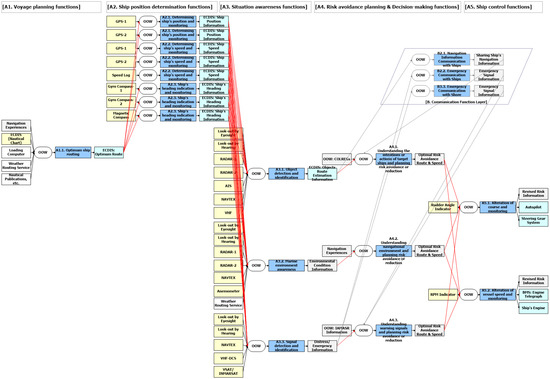
Figure A1.
Open-sea navigation function of conventional ships—simplified for illustration purposes (extracted from R2-MAS prototype software, version 0.2.3-alpha).
Figure A1.
Open-sea navigation function of conventional ships—simplified for illustration purposes (extracted from R2-MAS prototype software, version 0.2.3-alpha).
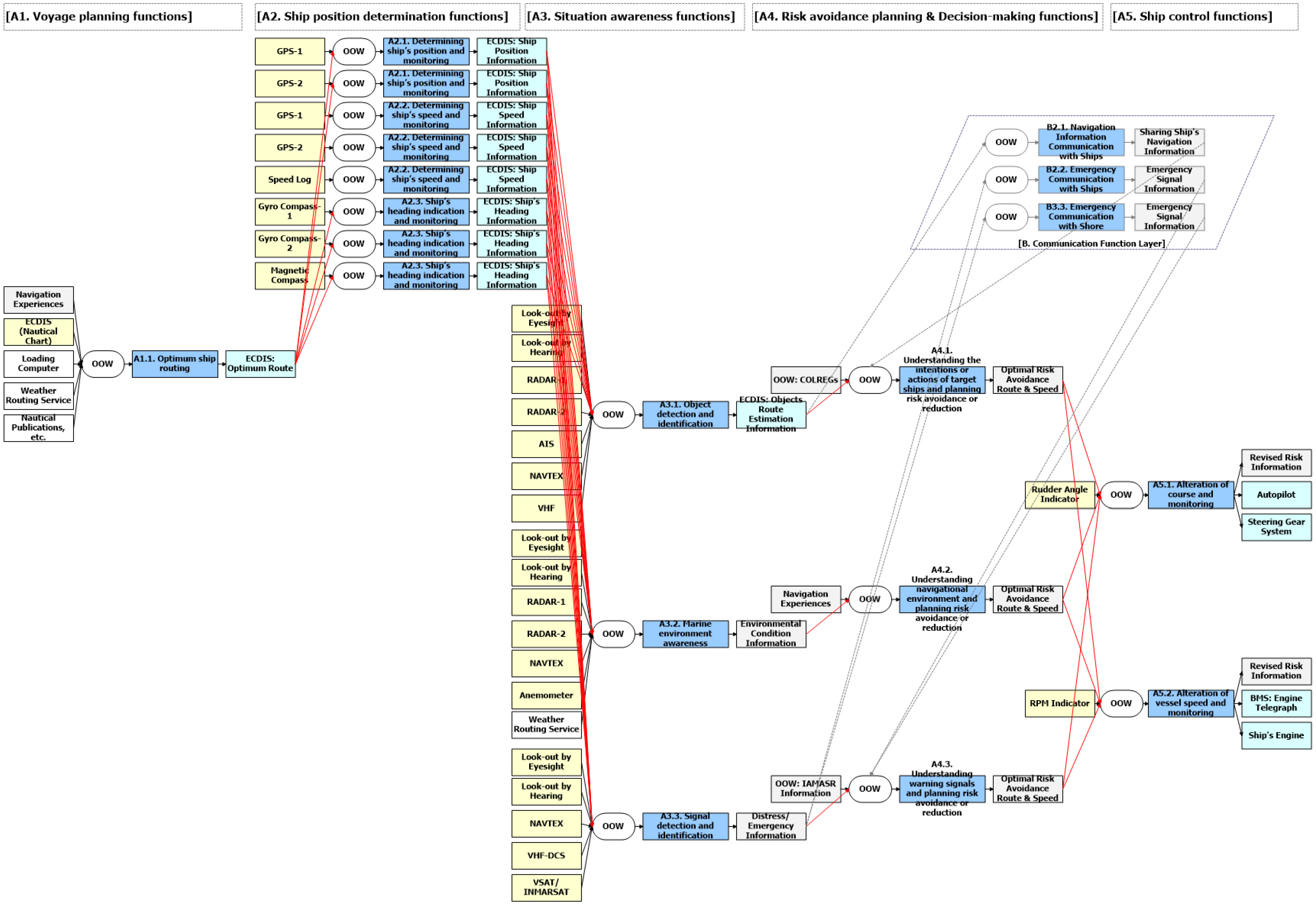
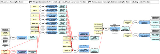
Figure A2.
Open-sea navigation function of Autonomous Navigation System—simplified for illustration purposes (extracted from R2-MAS prototype software, version 0.2.3-alpha).
Figure A2.
Open-sea navigation function of Autonomous Navigation System—simplified for illustration purposes (extracted from R2-MAS prototype software, version 0.2.3-alpha).
Appendix B. Example of Hazardous Scenarios Identified
The hazards and corresponding recommendations for risk reduction discussed during the HAZID Workshop are briefly summarized. To ensure conciseness, when similar content is identified as an existing safeguard (ES) or recommendation (R) in a previous hazardous scenario, then the phrase “Refer to Hazard ID-XX” is used to avoid redundant descriptions. Certain hazardous scenarios are excluded from the summary.
Table A1.
Examples of identified hazards and associated risk control measures.
Table A1.
Examples of identified hazards and associated risk control measures.
| ID | Cause or Hazard | Existing Safeguard (ES) | Recommendation (R) |
|---|---|---|---|
| A1.1-001 | Operation concept of KASS-ANS (K-ANS) is not clearly defined | (1) Operational envelope (OE) conditions for K-ANS: a. K-ANS can be used only in sea areas 5 NM away from territorial sea b. Control authority of ship (BMS and Autopilot control) is returned to the duty officer manually when the ship deviates from the course (planned route) by more than 2 NM (XTE ≤ 2 NM) c. K-ANS (control mode) can be used only when the KASS-Researcher(s) is on the bridge, etc. | (1) Operation Manual: a. Specify the procedure to check the planned route (ECDIS) on which the ship will be controlled by K-ANS in advance, by referring to nautical publications, etc. (e.g., information on dangerous objects/areas, underwater operations, military operations, etc., shall be checked in advance) b. Specify that K-ANS Control Mode can be used only in sea areas far enough from the shore (e.g., in sea areas 5 NM away from territorial sea) c. Specify that K-ANS Control Mode can be used only when KASS-Researchers are on board (on the bridge) d. Provide a clear procedure for transferring control authority between K-ANS and the duty officer e. Specify that KASS-MAP in K-ANS does not display the information from ENC and is not considered as an alternative to paper nautical charts (2) A warning plate/sign indicating that KASS-MAP in K-ANS is not considered as an alternative to paper nautical charts should be placed near equipment (3) Attach label tags to KASS system equipment to distinguish between legally required equipment and research equipment (KASS system) (4) Clearly specify, in the Operation Manual, the OE and/or ODD conditions required for starting K-ANS Control Mode and for returning control authority to the duty officer: e.g., weather conditions such as wave height, wind speed, visibility, current conditions, etc.; traffic conditions; prohibition of night operations; etc. (5) Provide a function to monitor the connection status of KASS systems and the connection status between external systems and K-ANS: - UI is required to check the data integrity between connected systems (so that the KASS-Researcher can start operating K-ANS once confirmation of normal conditions in the connected system is completed) - Specify procedures for checking systems connected to K-ANS in the Operation Manual (6) Provide a system monitoring function (with visual and audible alarm) so that data communication errors between internal systems of Digital Bridge can be recognized: - Display the normal or abnormal status of the connected systems (system errors are to be checked at the center console with alarms) (7) Operation Manual: - Provide a procedure and checklist to check the operating status of major equipment in advance: specify the major equipment check procedure (8) Define the operation concept of K-ANS clearly and specify the concept in the Operation Manual: e.g., K-ANS operation modes, areas of field test operation, method of field test operation, etc., should be clearly defined (9) Provide a system block diagram of the KASS system in order to prepare a brief description of KASS systems |
| A1.1-002 | Data error occurred when uploading the ship’s route information (waypoint) from ECDIS to K-ANS | - | (1) Provide a procedure to check the data integrity (Array) of the ship’s route data uploaded from ECDIS to K-ANS |
| A1.1-003 | Use of K-ANS by unauthorized person | (1) A safe navigational watch (human watch) is maintained at all times (2) Refer to A1.1-001-ES1.c | (1) Operation Manual: a. Provide procedures for the user login policy: only authorized users can access K-ANS Control Mode using login accounts (e.g., separate user accounts for K-ANS General Mode and K-ANS Control Mode) (2) Provide a warning plate indicating that unauthorized use is prohibited |
| A1.1-004 | Cybersecurity-related issues (cyber threat: cyber-attack, malware, etc.) | (1) Network segregation: KASS system uses a separate network (2) Cybersecurity gateway for KASS system is provided | (1) K-ANS shall comply with the requirements according to the cybersecurity level of the vessel |
| A1.1-005 | Error in K-ANS mode selection switch operation (human error, etc.) | (1) Refer to A1.1-001-ES1.c | (1) Provide operating procedures of K-ANS: simplified operating manuals (mode selection switch, etc.) should be placed near equipment (2) Check the necessity of providing a switch protector/switch guard for the K-ANS mode selection switch (to prevent accidental switch over between K-ANS Control Mode and Autopilot Standalone Mode) |
| A1.1-006 | Recording failure of ship’s data in VDR: e.g., K-ANS usage info, etc. | (1) K-ANS usage logs are recorded in the Digital Bridge system | (1) Operation Manual: a. Specify that K-ANS usage history shall be recorded in the bridge logbook (e.g., to record the start and end points of K-ANS Control Mode usage, etc.) |
| A2.1-001 | GPS failure/malfunction/connection failure: ship position information error | (1) Refer to A1.1-003-ES1 (2) Control authority of Autopilot and BMS is returned to the duty officer manually: with alarm (3) K-ANS is used only in the open sea | (1) Operation Manual: a. Specify that a proper bridge watch shall be maintained by a certified deck officer to determine the ship’s position at frequent intervals whenever circumstances allow/to check the ship’s heading and gyrocompass error frequently, even when K-ANS is used b. Specify operation procedures (that must be performed by the duty officer) for transferring control authority between K-ANS and the duty officer (e.g., manual operation procedure when control authority by K-ANS Control Mode is released, etc.) c. Provide emergency response procedures for major equipment failure (e.g., GPS failure, gyrocompass failure, etc.) (2) Provide visual and audible alarm functions in order to make the duty officer aware of the situation in which control authority by K-ANS Control Mode is released |
| A2.2-001 | Sensor equipment error: connection failure, etc. - AIS, rudder, speed log, AMS | (1) Refer to A1.1-003-ES1 (2) Monitoring function for data acquisition from sensor equipment: visual and audible alarm when sensor equipment error occurs | (1) Refer to A2.1-001-R1.b and c and A2.1-001-R2 (2) Consider providing a function to display the status of interfaced equipment (e.g., normal or abnormal state, etc.) by categorizing them according to data importance: - The operator can recognize the status of the equipment connected - Information can be provided to the operator to determine whether emergency response actions (e.g., control authority return procedure, etc.) are necessary |
| A2.3-001 | Gyrocompass failure | (1) Refer to A2.1-001 | (1) Refer to A2.1-001 |
| A3.1-001 | Contamination of image sensors by heavy snow/rain, rainstorm, lightning, extreme temperature, etc. Temperature/humidity/electromagnetic wave | (1) Refer to A1.1-003-ES1 | (1) Provide image sensor (vision camera) installation guidance: a. Image sensors shall be positioned in a location that minimizes the effects of snow, rain, etc. (housing, etc., can be installed) b. Image sensors shall be positioned in a location for easy maintenance access (2) Operation Manual: a. Specify that great caution is required for K-ANS operation depending on the weather conditions, such as heavy snow/rain, dense fog, etc. b. Provide periodic maintenance procedures for K-ANS, including image sensor systems, and specify the maintenance procedures in the Operation Manual c. Specify the minimum approach distance for other ships, defined as a CPA range of 4 NM (distance measured by RADAR), for collision avoidance: provide operation procedures for transferring control authority to the duty officer for situations such as when a vessel appears within the CPA range boundary of 4 NM, etc. d. Provide a function to indicate the importance of sensor equipment used for the collision avoidance algorithm of K-ANS (e.g., in order of importance, such as AIS, radar, vision cameras, etc.) |
| A3.1-002 | Dense fog/night navigation (when in difficult visibility situations, such as fog, darkness, etc.) | (1) Refer to A1.1-003-ES1 (2) Field testing of K-ANS will be conducted during the daytime only | (1) Operation Manual: a. Refer to A3.1-001-R2.a b. Clarify OE conditions for K-ANS, such as visibility conditions, wind speed, etc. (e.g., absolute wind speed ≤ BN 6, visibility condition ≥ 6 NM) |
| A3.1-003 | Failure of object recognition function: radar failure, etc. Error in one image sensor: e.g., object detection datasets are different from one another | (1) Refer to A1.1-003-ES1 (2) Periodic maintenance procedures for the KASS system | (1) Review the appropriate minimum distance range for K-ANS collision avoidance functions considering the characteristics of the own ship and specify the minimum range of CPA for K-ANS collision avoidance (e.g., CPA > 4 NM) (2) Provide a menu item for setting the appropriate minimum distance range for the K-ANS collision avoidance function (e.g., setting CPA or setting TCPA/DCPA, etc.) (3) Operation Manual: - Provide the OE or ODD conditions under which K-ANS Control Mode cannot be started/activated, e.g., when a vessel posing a risk of collision is within the minimum distance boundary (e.g., within the CPA range boundary of 4 NM, etc.) (4) Provide a function (or define OE conditions) for returning control authority to the duty officer with an alarm when a vessel appears inside the minimum distance boundary (e.g., within the CPA range boundary of 4 NM, etc.) during K-ANS Control Mode - Example/meaning of a vessel occurring within the minimum distance boundary: sudden appearance of a vessel, or K-ANS does not perform a collision avoidance action until a vessel posing a risk of collision enters the minimum distance boundary, etc. (5) Provide a function (or define OE conditions) for returning control authority to the duty officer with an alarm when there are two (2) or more vessels on a collision course (posing a risk of collision) during K-ANS Control Mode: the number of target vessels (that can be used in the collision avoidance field test for K-ANS Control Mode) will be determined and provided by the ship owner at a later date (6) A simulation test report (including collision avoidance simulation tests) for various 1:N encounter scenarios should be submitted |
| A3.1-005 | Simultaneous occurrence of multiple objects (ships, etc.) | (1) Refer to A1.1-003-ES1 | (1) Refer to A3.1-003-R3, A3.1-003-R4, A3.1-003-R5, and A3.1-003-R6 |
| A3.1-006 | Inadequate object recognition: an inconspicuous, partly submerged vessel or object, or combination of such vessels or objects being towed, etc. Fishing nets, etc. | (1) Refer to A1.1-003-ES1 | (1) Refer to A1.1-001-R1.a |
| A3.1-007 | Inadequate object recognition: such as “vessel not under command”, “vessel restricted in her ability to maneuver”, etc. | (1) Refer to A1.1-003-ES1 | (1) Refer to A3.1-003-R6 |
| A4.1-001 | Collision Risk Index calculation error: - AIS data error, - Radar data error: ghost objects, etc. | (1) Refer to A1.1-003-ES1 | (1) Refer to A3.1-003-R6 |
| A4.1-002 | Non-compliance with COLREGs: the own vessel is in a “give-way” situation - Definition of non-compliance with COLREGs: A situation in which adherence to the COLREGs is not feasible due to specific circumstances | (1) Refer to A1.1-003-ES1 | (1) Provide a function to alert the duty officer in advance in situations where K-ANS determines a direction for collision avoidance (collision avoidance route) in a way that does not comply with the COLREGs: check whether the KASS-Researcher can continuously provide collision avoidance route information (course alteration plan by K-ANS Control Mode) in advance before giving the command signal through the interface connected to the Autopilot (2) Operation Manual: - Specify that, before performing any collision avoidance action, the duty officer should contact the approaching vessel directly via VHF communication in order to inform the other vessel of the use of Autonomous Navigation System (K-ANS Control Mode) and to communicate the collision avoidance action plan in advance, for all situations in which collision avoidance actions are initiated by K-ANS Control Mode - Provide procedures for contacting other vessels via VHF communication during K-ANS Control Mode (3) Operation Manual: a. Clarify operational envelope (ODD and/or OE) conditions for K-ANS Control Mode |
| A4.1-003 | The criteria for when to take action to avoid collision are unclear when the give-way vessel fails to take appropriate action in compliance with COLREGs: the own vessel is in a “stand-on” vessel situation | (1) Refer to A1.1-003-ES1 | (1) Refer to A4.1-002-R1, A4.1-002-R2, A4.1-002-R3, and A3.1-003-R6 |
| A5.1-001 | Sudden release of K-ANS control while collision avoidance action is being taken: e.g., major equipment failure, etc. | (1) Refer to A1.1-003-ES1 (2) Refer to A2.1-001-ES2 | (1) Operation Manual: a. Provide and specify control override policy: operational envelope conditions and control override procedures b. Check whether there is an unintentional release of K-ANS control scenario and provide response procedures if such a scenario exists c. Specify operational envelope (OE) conditions for starting K-ANS Control Mode and for returning control authority to the duty officer separately d. Specify that transferring control authority between K-ANS and the duty officer (K-ANS Control Mode on and off) is performed manually by the duty officer e. Specify that K-ANS Control Mode field test should be conducted within one shift (4 h) and should avoid being performed during shift times (when the duty officer is being relieved) (2) Maintain education/training records for use of K-ANS (Control Mode) - Provide training for the ship’s officers and KASS-Researchers on board |
| A5.1-002 | Autopilot connection failure (software error, etc.) | (1) Refer to A1.1-003-ES1 (2) Refer to A2.1-001-ES2 | (1) Define operation concept of K-ANS and Autopilot clearly - Autopilot modes need to be determined (e.g., Non-Follow Up, Hand Mode, Autopilot Mode, K-ANS Mode, etc.) - Control override policy for K-ANS shall be defined: e.g., in an emergency situation (connection failure with Autopilot, etc.), K-ANS Control Mode can be overridden in Autopilot Hand Mode manually (2) Operation Manual: - Provide emergency response procedures for the connection failure scenarios between K-ANS and Autopilot - Specify that the priority is to use Autopilot Hand Mode when a connection failure occurs between K-ANS and Autopilot - Specify limitations on the range of rudder angle controlled by K-ANS Control Mode (e.g., 10 degrees to both port and starboard sides, etc.) |
| A5.2-001 | Sudden release of K-ANS control while collision avoidance action is being taken: e.g., major equipment failure, etc. | (1) Refer to A1.1-003-ES1 (2) Refer to A2.1-001-ES2 | (1) Refer to A5.1-001-R1, and A5.1-001-R2 (2) Audible alarms indicating the release of K-ANS Control Mode shall be easily distinguishable from other alarms (existing alarms on the bridge) to avoid confusion in a crisis situation |
| A5.2-002 | BMS data communication error (between K-ANS control and BMS) | (1) Refer to A1.1-003-ES1 (2) Visual and audible alarm for data communication errors (e.g., echo signal time-out, etc.) between K-ANS and BMS (3) Override function - If K-ANS Control Mode is aborted, the engine RPM set by K-ANS is maintained until the duty officer adjusts it | (1) Define operation concept of K-ANS and BMS control clearly - It is necessary to check the safe speed (engine RPM) of the ship in case BMS control by K-ANS Control Mode is aborted (due to data communication failure, etc.): specify a control override policy stating that if K-ANS Control Mode is aborted, the engine RPM set by K-ANS shall be maintained until the duty officer adjusts it - Taking the above into consideration, it is necessary to hold discussions on the operation concept with the BMS supplier (2) Operation Manual: - Specify the BMS control range (allowable/available main engine RPM range) that can be controlled by K-ANS: the shipowner will present the allowable range of RPM that can be controlled by K-ANS - Provide emergency response procedures for connection failure scenarios between K-ANS and BMS (3) Provide a function that releases K-ANS Control Mode when excessive manual operation of the BMS is performed by the duty officer while in K-ANS Control Mode (specify range value of excessive manual operation based on the RPM change rate) (4) Provide a control override policy stating that if K-ANS Control Mode is aborted, the engine RPM set by K-ANS Control Mode shall be maintained until the duty officer adjusts it |
References
- IMO. MSC.1/Circ.1604. Interim Guidelines for MASS Trials; IMO: London, UK, 2019. [Google Scholar]
- IMO. IMO Takes First Steps to Address Autonomous Ships. 2018. Available online: https://www.imo.org/en/MediaCentre/PressBriefings/Pages/08-MSC-99-mass-scoping.aspx (accessed on 27 December 2024).
- IMO. IMO and Autonomous Shipping. Available online: https://www.imo.org/en/MediaCentre/HotTopics/Pages/Autonomous-shipping.aspx (accessed on 27 December 2024).
- IMO. Maritime Safety Committee—109th Session (MSC 109). 2024. Available online: https://www.imo.org/en/MediaCentre/MeetingSummaries/Pages/MSC-109th-session.aspx (accessed on 27 December 2024).
- Chang, C.; Kontovas, C.; Yu, Q.; Yang, Z. Risk Assessment of the operations of maritime autonomous surface ships. Reliab. Eng. Syst. Saf. 2021, 8, 206–222. [Google Scholar] [CrossRef]
- Vos, J.D.; Hekkenberg, R.G.; Banda, O.V. The Impact of Autonomous Ships on Safety at Sea—A Statistical Analysis. Reliab. Eng. Syst. Saf. 2021, 210, 107558. [Google Scholar] [CrossRef]
- Hogg, T.; Ghosh, S. Autonomous merchant vessels: Examination of factors that impact the effective implementation of unmanned ships. Aust. J. Marit. Ocean Aff. 2016, 8, 206–222. [Google Scholar] [CrossRef]
- Kretschmann, L.; Burmeister, H.C.; Jahn, C. Analyzing the economic benefit of unmanned autonomous ships: An exploratory cost-comparison between an autonomous and a conventional bulk carrier. Res. Transp. Bus. Manag. 2017, 25, 76–86. [Google Scholar] [CrossRef]
- Ziajka-Poznanska, E.; Montewka, J. Costs and Benefits of Autonomous Shipping—A Literature Review. Appl. Sci. 2021, 11, 4553. [Google Scholar] [CrossRef]
- Dantas, J.L.D.; Theotokatos, G. A framework for the economic-environmental feasibility assessment of short-sea shipping autonomous vessels. Ocean Eng. 2023, 279, 114420. [Google Scholar] [CrossRef]
- Burmeister, H.; Bruhn, W.; Rødseth, Ø.; Porathe, T. Autonomous Unmanned Merchant Vessel and its Contribution towards the e-Navigation Implementation: The MUNIN Perspective. Int. J. e-Navig. Marit. Econ. 2014, 1, 1–13. [Google Scholar] [CrossRef]
- Komianos, A. The Autonomous Shipping Era. Operational, Regulatory, and Quality Challenges. TransNav Int. J. Mar. Navig. Saf. Sea Transp. 2018, 12, 335–348. [Google Scholar] [CrossRef]
- Tao, J.; Liu, Z.; Wang, X.; Cao, Y.; Zhang, M.; Loughney, S.; Wang, J.; Yang, Z. Hazard identification and risk analysis of maritime autonomous surface ships: A systematic review and future directions. Ocean Eng. 2024, 307, 118174. [Google Scholar] [CrossRef]
- Li, W.; Chen, W.; Guo, Y.; Hu, S.; Xi, Y.; Wu, J. Risk Performance Analysis on Navigation of MASS via a Hybrid Framework of STPA and HMM: Evidence from the Human-Machine Co-Driving Mode. J. Mar. Sci. Eng. 2024, 12, 1129. [Google Scholar] [CrossRef]
- Chaal, M.; Ren, X.; BahooToroody, A.; Basnet, S.; Bolbot, V.; Banda, O.A.V.; Gelder, P.V. Research on risk, safety, and reliability of autonomous ships: A bibliometric review. Saf. Sci. 2023, 167, 106256. [Google Scholar] [CrossRef]
- Yuzui, T.; Kaneko, F. Toward a hybrid approach for the risk analysis of maritime autonomous surface ships: A systematic review. J. Mar. Sci. Technol. 2025, 30, 153–176. [Google Scholar] [CrossRef]
- Sumon, M.M.A.; Kim, H.; Na, S.; Choung, C.; Kjønsberg, E. Systems-Based Safety Analysis for Hydrogen-Driven Autonomous Ships. J. Mar. Sci. Eng. 2024, 12, 1007. [Google Scholar] [CrossRef]
- Chaal, M.; Banda, O.A.V.; Glomsrud, J.A.; Basnet, S.; Hirdaris, S.; Kujala, P. A framework to model the STPA hierarchical control structure of an autonomous ship. Saf. Sci. 2020, 132, 104939. [Google Scholar] [CrossRef]
- Banda, O.A.V.; Kannos, S.; Goerlandt, F.; Gelder, P.H.A.J.M.; Bergström, M.; Kujala, P. A systemic hazard analysis and management process for the concept design phase of an autonomous vessel. Reliab. Eng. Syst. Saf. 2019, 191, 106584. [Google Scholar] [CrossRef]
- Wróbel, K.; Montewka, J.; Kujala, P. System-theoretic approach to safety of remotely-controlled merchant vessel. Ocean Eng. 2018, 152, 334–345. [Google Scholar] [CrossRef]
- Wróbel, K.; Montewka, J.; Kujala, P. Towards the development of a system-theoretic model for safety assessment of autonomous merchant vessel. Reliab. Eng. Syst. Saf. 2018, 178, 209–224. [Google Scholar] [CrossRef]
- Ventikos, N.P.; Chmurski, A.; Louzis, K. A systems-based application for autonomous vessels safety: Hazard identification as a function of increasing autonomy levels. Saf. Sci. 2020, 131, 104919. [Google Scholar] [CrossRef]
- Guo, C.; Haugen, S.; Utne, I.B. Risk assessment of collisions of an autonomous passenger ferry. Proc. Inst. Mech. Eng. Part O 2023, 237, 425–435. [Google Scholar] [CrossRef]
- Guo, C.; Utne, I.B. Development of risk indicators for losing navigational control of autonomous ships. Ocean Eng. 2022, 266, 113204. [Google Scholar] [CrossRef]
- Gao, C.; Guo, Y.; Zhong, M.; Liang, X.; Wang, H.; Yi, H. Reliability analysis based on dynamic Bayesian networks: A case study of an unmanned surface vessel. Ocean Eng. 2021, 240, 109970. [Google Scholar] [CrossRef]
- Fan, C.; Montewka, J.; Zhang, D. Towards a Framework of Operational-Risk Assessment for a Maritime Autonomous Surface Ship. Energies 2021, 14, 3879. [Google Scholar] [CrossRef]
- Fan, C.; Montewka, J.; Zhang, D. A risk comparison framework for autonomous ships navigation. Reliab. Eng. Syst. Saf. 2022, 226, 108709. [Google Scholar] [CrossRef]
- Wróbel, K.; Montewka, J.; Kujala, P. Towards the assessment of potential impact of unmanned vessels on maritime transportation safety. Reliab. Eng. Syst. Saf. 2017, 165, 155–169. [Google Scholar] [CrossRef]
- Sahin, B.; Yazidi, A.; Roman, D.; Soylu, A. Ontology-Based Fault Tree Analysis Algorithms in a Fuzzy Environment for Autonomous Ships. IEEE Access 2021, 9, 40915–40932. [Google Scholar] [CrossRef]
- Shiokari, M.; Itoh, H.; Yuzui, T.; Ishimura, E.; Miyake, R.; Kudo, J.; Kawashima, S. Structure model-based hazard identification method for autonomous ships. Reliab. Eng. Syst. Saf. 2024, 247, 110046. [Google Scholar] [CrossRef]
- Lee, C.; Lee, S. A Risk Identification Method for Ensuring AI-Integrated System Safety for Remotely Controlled Ships with Onboard Seafarers. J. Mar. Sci. Eng. 2024, 12, 1778. [Google Scholar] [CrossRef]
- Abaei, M.M.; Hekkenberg, R.; BahooToroody, A. A multinomial process tree for reliability assessment of machinery in autonomous ships. Reliab. Eng. Syst. Saf. 2021, 210, 107484. [Google Scholar] [CrossRef]
- Chaal, M.; Bahootoroody, A.; Basnet, S.; Banda, O.A.V.; Goerlandt, F. Towards system-theoretic risk assessment for future ships: A framework for selecting Risk Control Options. Ocean Eng. 2022, 259, 111797. [Google Scholar] [CrossRef]
- Utne, I.B.; Rokseth, B.; Sørensen, A.J.; Vinnem, J.E. Towards supervisory risk control of autonomous ships. Reliab. Eng. Syst. Saf. 2020, 196, 106757. [Google Scholar] [CrossRef]
- Johansen, T.; Utne, I.B. Supervisory risk control of autonomous surface ships. Ocean Eng. 2022, 251, 111045. [Google Scholar] [CrossRef]
- Johansen, T.; Blindheim, S.; Torben, T.R.; Utne, I.B.; Johansen, T.A.; Sørensen, A.J. Development and testing of a risk-based control system for autonomous ships. Reliab. Eng. Syst. Saf. 2023, 234, 109195. [Google Scholar] [CrossRef]
- Basnet, S.; BahooToroody, A.; Chaal, M.; Lahtinen, J.; Bolbot, V.; Banda, O.A.V. Risk analysis methodology using STPA-based Bayesian network—Applied to remote pilotage operation. Ocean Eng. 2023, 270, 113569. [Google Scholar] [CrossRef]
- Li, P.; Wang, Y.; Yang, Z. Risk assessment of maritime autonomous surface ships collisions using an FTA-FBN model. Ocean Eng. 2024, 309, 118444. [Google Scholar] [CrossRef]
- Wu, Q.; Wang, T.; Diaconeasa, M.A.; Mosleh, A.; Wang, Y. A Comparative Assessment of Collision Risk of Manned and Unmanned Vessels. J. Mar. Sci. Eng. 2020, 8, 852. [Google Scholar] [CrossRef]
- Zhang, D.; Han, Z.; Zhang, K.; Zhang, J.; Zhang, M.; Zhang, F. Use of Hybrid Causal Logic Method for Preliminary Hazard Analysis of Maritime Autonomous Surface Ships. J. Mar. Sci. Eng. 2022, 10, 725. [Google Scholar] [CrossRef]
- KASS Project. Korea Autonomous Surface Ship Project. Available online: https://www.kassproject.org/en/main.php (accessed on 18 March 2025).
- MSC.1/Circ.1455; Guidelines for the Approval of Alternatives and Equivalents as Provided for in Various IMO Instruments. IMO: London, UK, 2013.
- MSC-MEPC.2/Circ.12/Rev.2; Revised Guidelines for Formal Safety Assessment (FSA) for Use in the IMO Rule-Making Process. IMO: London, UK, 2018.
- IEC/ISO 31010; Risk Management—Risk Assessment Techniques, Edition 2. IEC: Geneva, Switzerland, 2019.
- Endsley, M.R. Toward a Theory of Situation Awareness in Dynamic Systems. Hum. Factors 1995, 37, 32–64. [Google Scholar] [CrossRef]
- Kim, H.T.; Na, S. Development of a Human Factors Investigation and Analysis Model for Use in Maritime Accidents: A Case Study of Collision Accident Investigation. J. Navig. Port Res. 2017, 41, 303–318. [Google Scholar]
- Russell, S.J.; Norvig, P. Intelligent Agents. In Artificial Intelligence: A Modern Approach, 4th ed.; Pearson Education Limited: Upper Saddle River, NJ, USA, 2021. [Google Scholar]
- COLREGs, IMO Convention on the International Regulations for Preventing Collisions at Sea, 1972. Available online: https://www.imo.org/en/About/Conventions/Pages/COLREG.aspx (accessed on 27 December 2024).
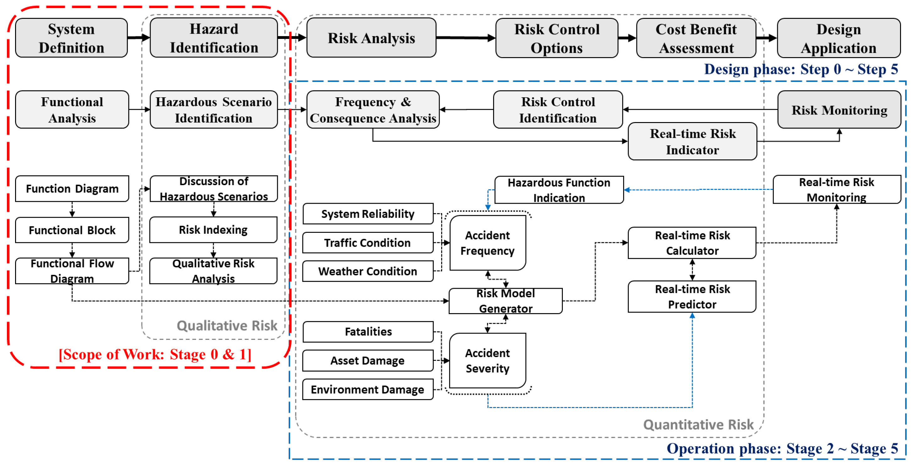
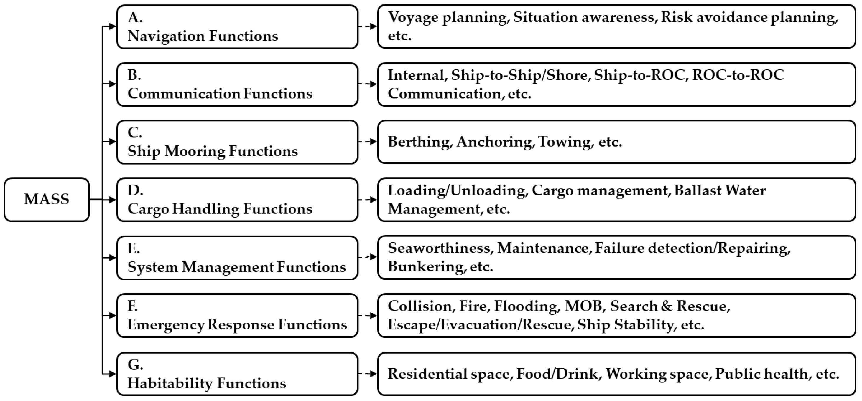
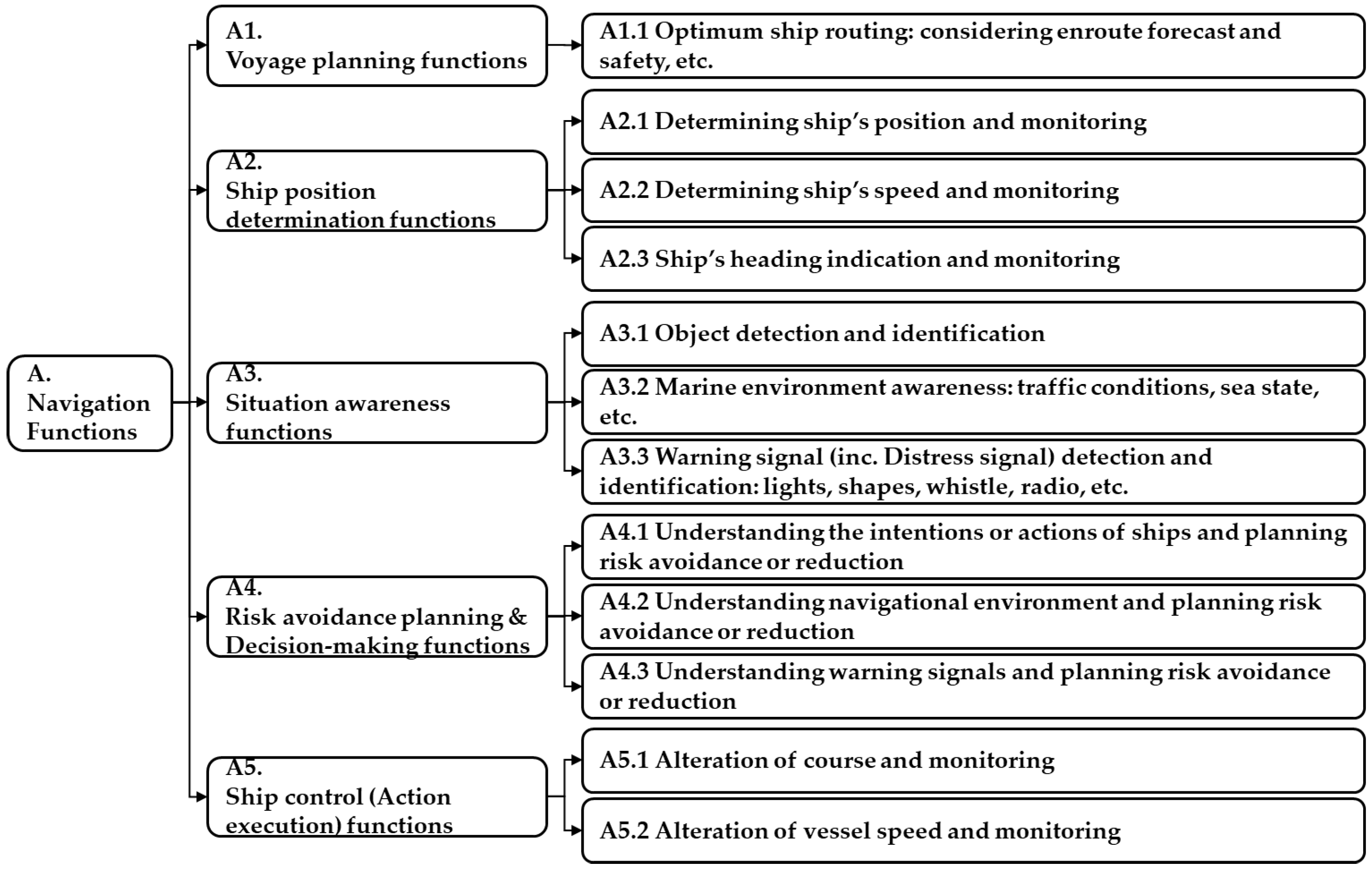
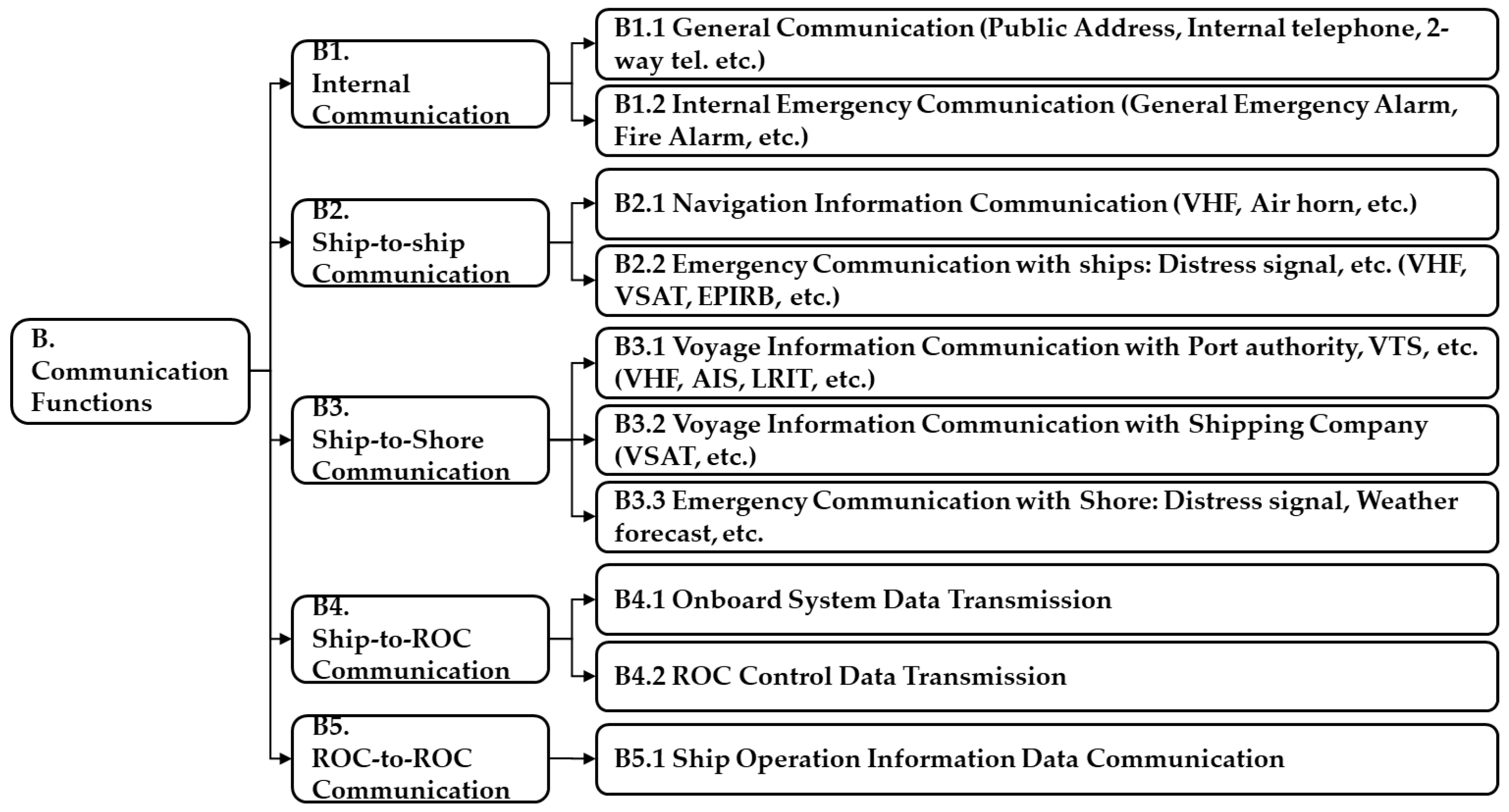
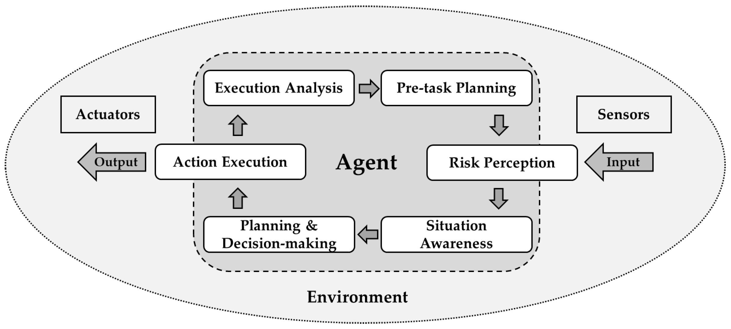
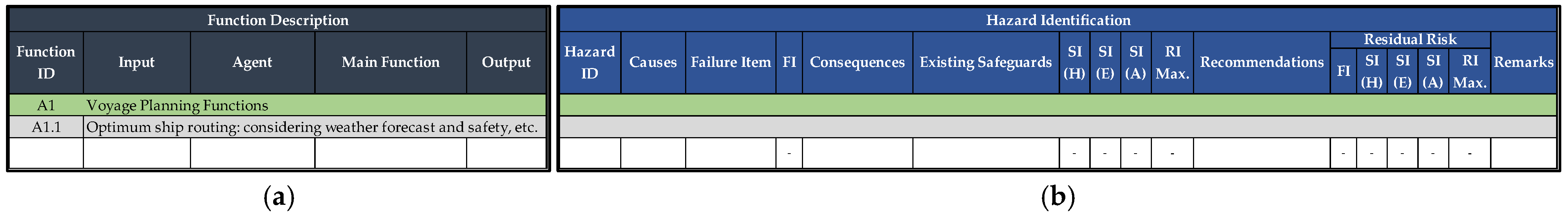


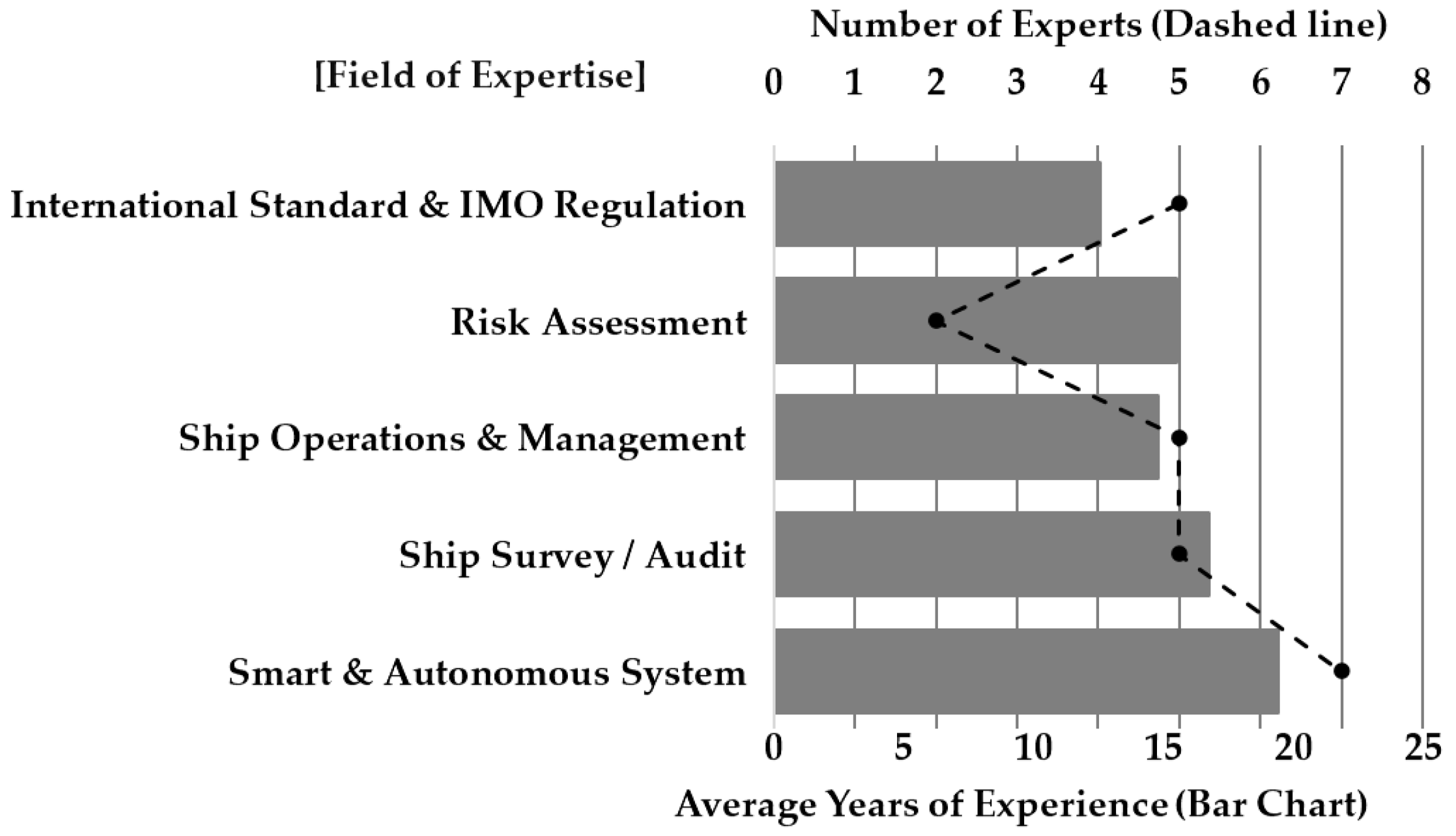
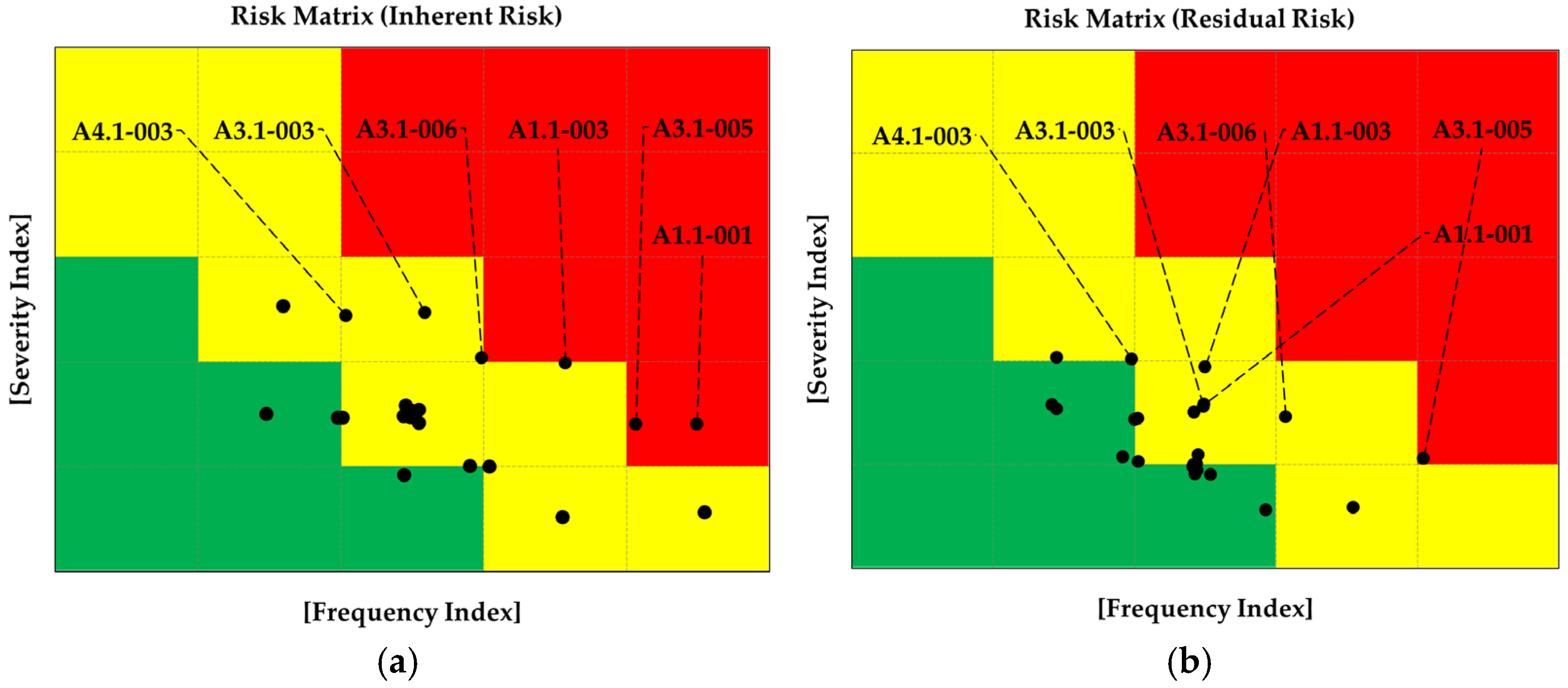
Disclaimer/Publisher’s Note: The statements, opinions and data contained in all publications are solely those of the individual author(s) and contributor(s) and not of MDPI and/or the editor(s). MDPI and/or the editor(s) disclaim responsibility for any injury to people or property resulting from any ideas, methods, instructions or products referred to in the content. |
© 2025 by the authors. Licensee MDPI, Basel, Switzerland. This article is an open access article distributed under the terms and conditions of the Creative Commons Attribution (CC BY) license (https://creativecommons.org/licenses/by/4.0/).